SJSoane
-
Posts
1,655 -
Joined
-
Last visited
Content Type
Profiles
Forums
Gallery
Events
Everything posted by SJSoane
-
 Hi everyone, So here is a perplexing issue, that shows I don't really understand these ships yet. I was setting up a sanding template for the quarterdeck beams, in anticipation of making the transom at the stern. I measured from my Admiralty drawings in the sheer plan that the deck rounds up 8 ½" at midship, which is 40'-8" wide. At the stern transom it measures a 5" round up, over a width of 21'-5". This clearly is not the same radius at midship and at the stern. The ship is roughly twice as wide at the center as at the stern, but the roundups do not double. So, are the radii of the beams different along the length of the deck? This was less noticeable on the gun deck, with a smaller roundup. Best wishes, Mark
 -
Thanks, Gaetan, I'll track it down.
-
Hi Gaetan, I look forward to seeing the entire presentation, if you want to post it here when you are done. By the way, I read in the first page of information that you used Bokens linen thread, size 90. Is that thread free of the little bumps or blurbs that I have found in linen thread so far? At my scale of 1:64, the bumps really show up when I have made up a line on the ropewalk. I am still on the search for good linen thread! Best wishes, Mark
-
ROYAL CAROLINE 1749 by Doris - 1:40 - CARD
SJSoane replied to DORIS's topic in - Build logs for subjects built 1501 - 1750
Hi Doris, Your photos defy description. It is hard to imagine this kind of detail at any scale, and even more, built out of card! Could you give us a little more information on how you built the small details, like the table settings, chairs, etc. Is some of this papier-mâché? And how did you get such smooth finishes? I was thinking about building a captain's table and chairs in my Bellona project someday, but I was thinking about a simple trestle table. You have inspired me to think a little more boldly! Best wishes, Mark- 883 replies
-
- 1
-

-
- royal caroline
- ship of the line
- (and 1 more)
-
Hi Michael, I just had a chance to look over your new project. I'll be watching this one. Like others, I am very impressed by your building jig. I look forward to seeing how it works for you. That must have been very scary when the mill broke. A timely reminder of wearing eye protection at all times. I will be curious to hear more about your wood bending. Are you getting spring-back? and if so, how are you compensating for that when setting up the bending jigs? Best wishes for the new year, Mark
-
Hi Ed, The project is looking great. Interesting way of clamping, with driven pins. Can you tell me a little more about what kinds of pins you are using, and do you size the drilled hole a tiny bit smaller than the measured diameter of the pin? Hammering always looks a little scary on a model.... Best wishes, Mark
-
Hi Remco, Funny thing about research. You don't often see things unless you are explicitly looking for them, and sometimes you see them but they don't yet make sense. Even after studying drawings for some time before a build, we don't really understand some of it until we start building. So unless we are willing to go back and tear out everything that we now understand differently, our models will always be a little out of sync with our current understanding. This is especially true with the more schematic admiralty drawings that you and I are working from, where not much detail is shown. I have sometimes fantasized about building the Bellona again, only closer to my current understanding. But I quickly put those thoughts aside. Only you and the original shipwright will know for sure where your outstanding model deviates from the original. best wishes, Mark
- 1,215 replies
-
- 1
-
-
- sloop
- kingfisher
- (and 1 more)
-
Hi Gaetan, That is a spectacular presentation. Beautiful sheets. I am not sure I would change this because of one person's comments. I participate in a number of juries for architecture projects, and I am amazed how one year a group of jurors will love a project that the last year's group disliked or ignored. It really is more subjective than one would believe. But use your best judgement. best wishes for the new year, Mark
- 728 replies
-
- 3
-
-
- le fleuron
- 64 gun
- (and 1 more)
-
Hi everyone, Thank you, remco, grant and brian for your comments. They help keep me going. druxey, beautiful model, exquisitely built! What I am thinking about on the carlings for the upper deck is a way to scribe the carlings locations right at the start. On the gun deck, I penciled the lines, and later they faded a bit. I like the idea of getting a positive scribed line against which to register the chisel. Did you pencil or scribe to get such perfect alignment? Alex, you are right that this is a matter of taste. I fell in love with the admiralty models in the National Maritime Museum in London many years ago, and could not get the color scheme out of my head. I do worry a bit about red inboard planking, which is the admiralty norm, but druxey's photo in the last post shows how effective this can be. I may try some dummy setups of colored card to see how it looks before committing. I had to throw away my original riding bitts, because I painted them, and they were too garish. Red stain was more effective, a little more subtle for me. Greg, interesting to hear that you are rethinking color. It is difficult. I sympathize with remco's concern about losing some of the detail in his beautiful masts if he stains the tops black; but then the blackened mast heads look great from afar. I may have a scotch before deciding myself... Gaetan, thank you for the vote of approval. I will thank you again publicly for the great advice on craftsmanship. I was able to work much faster, and more accurately, keeping to one step at a time, and processing as many similar pieces as possible at the same time. I have attached a couple of photos of the stern timbers beginning to take form. A lot still to go! Best wishes, Mark

-
Karl, Beautiful work. It gets better with every detail. Can you remind me how you are marking the joints between the planks on the sides? It shows the joint nicely, but it is subtle at the same time. Best wishes, Mark
- 662 replies
-
- 2
-
-
- bonhomme richard
- frigate
- (and 1 more)
-
Thanks, druxey and Greg. Fairing the carlings to run sweetly fore and aft turned out to be more difficult that I ever would have expected. Even the slightest discrepancy in the mortises in the beams show up as a waver in the line of carlings. I am working on some ideas for doing this more efficiently on the upper deck. Good thing I have a lot of decks to practice on.... And thanks to Gary, who gave me some great insights on next steps, on his Alfred build site. And a happy new year to all of you. New modeling challenges in the new year, new tools to buy or at least to think about buying....;-) Best wishes, Mark
-
HI Remco, Looking great. I have tried unsuccessfully to find a solution to scribing in tight quarters that your washer does perfectly. That is definitely going into my toolbox! Best wishes, Mark
-
Hi Gary, I just caught up with your postings. It is looking terrific! I always wondered what that quarter circle between the riding bitts represented in the sheer plan. Mine has no detail, and so I just ignored it. I may try building one like yours, for the Bellona. Where did you find details? I am also inspired by your rhodings. Did you mill them out of a single piece of metal before drilling? Very clever. I also see your upper deck transom more clearly. I have been working through the geometry of the Bellona's stern, and I noticed that this transom would run smack into the rudder head. I was thinking that it would have to be cut, which would make no structural sense. Your bending it forward around the rudder makes perfect sense. I could find no drawings or photos of this looking aft or in plan, so I was shooting in the dark. Steel's 80 gun ship drawings show the transom further aft, and able to clear the rudder. But the Bellona's lower counter is too close to the rudder for this to work. Very complex, these sterns. You continue to inspire and educate me! Best wishes, Mark
-
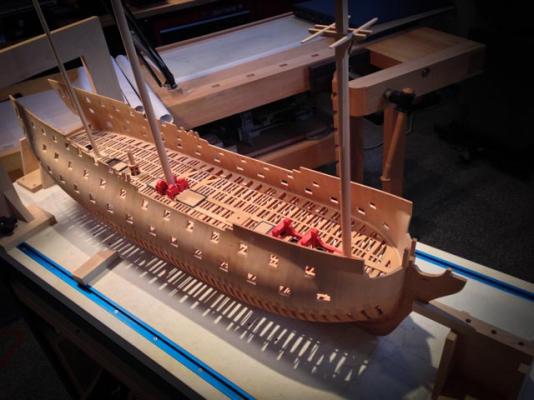
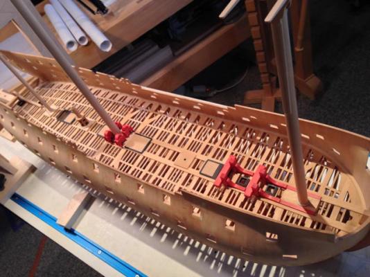
Hi everyone, I finally got time over the holidays to get back into the shop and to check out the website. Thank you Ron, and Sailor 123... for your comments. The 74 gun ship of the mid 18th century has the perfect balance of form and function--I learn something new every day about how elegantly the shipwrights met a functional need with a beautiful form. Guy, I would be happy to see anything you might turn up on the Bellona. I finally finished the gun deck framing. I did it in record time, compared to my previous work. I followed Gaetan's advice from some time ago, to keep working systematically at the same task, and it will become easier and faster. I worked out a systematic way of numbering the ledges, and I was able to do each process on each piece, before going back to do the next process on each piece. It helped with a rhythm, and it meant the whole deck was built up in each stage. It was harder that way to say that I had finished a few more bays, and could come back later for the remaining bays. I had to keep working to see any real progress, and then it was all done. It seemed to work for me! I counted up. There are 525 pieces in the deck framing itself--beams, carlings, ledges, and knees. And 856 mortices. I am moving on to framing the stern, for a nice change of scenery. I have made some very interesting discoveries about the Bellona framing, while drafting it up. More on that later. Best wishes, Mark


-
Hi Kobus, I am glad you found the grating details helpful. As you can see from earlier photos in this build log, I built the first ones way out of scale. It was worth trying again. Best wishes, Mark
-
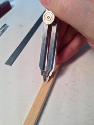
I also use them to divide up lengths into equal parts. For example, finding the quarters on a mast, or the spaces between ledges marked out on a carling. It is fiddly to set the screw at exactly the right place, so I always double check on a piece of paper. If I set it at 3, for example, I mark out a line on a piece of paper, and walk the dividers down the line three times. If it exactly lands on the end mark of the line you are set; if not, adjust slightly and try again. I find this infinitely easier than doing the math to divide a length, or the old draftsman trick of laying a scale diagonally across two lines to match even divisions on the scale. Recently, I also used this to set off the diameters of masts at the various quarters. I set the proportional dividers to 2, and used the long legs to measure the correct diameter against an accurate decimal inch ruler. I could then use the short legs to mark half the diameter on either side of the center line. Much faster than dividing the diameter mathematically, and then try to set it off on either side. When you realize that these ships were designed extensively with proportional systems and rules, it is kind of fun to play with the idea of proportions as you construct. Mark
-
Grating dimensions
SJSoane replied to KobusBeukes's topic in Building, Framing, Planking and plating a ships hull and deck
Further note: I had earlier built the gratings in the normal method of a table saw jig, but my first gratings were way out of scale because I did not have a slitting saw of the exact right dimension. In round two, which you can see at postings number 87 and 93, I used a slitting saw on a mill, which allowed me to dial in exact sizes including moving the saw over slightly after the first cut for each groove to make the exact right size of groove. The construction method itself used an idea developed by Clay Feldman, which avoids the problem of assembling tiny pieces in two directions. Best wishes, Mark -
Grating dimensions
SJSoane replied to KobusBeukes's topic in Building, Framing, Planking and plating a ships hull and deck
Hi everyone, Steel says, for all sizes of ship, "Grating battens to be 2 ¾" broad, and ¾" thick. The ledges and battens to be of oak, the gratings substantially made, and the openings not more than 2 ¾" square." On the page labeled Folio XXIII. The ledges vary according to size of ship. For my 74 gun ship, they are 3" thick and 4" deep. This is what it looks like at my scale of 3/16" = 1'-0". I showed one way to construct this in my build log. Best wishes, Mark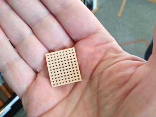
-
Hi Remco, I just saw your posting on Facebook, and noticed your gun barrels. I don't see anything about that on your posting here. They are beautifully detailed; can you show a few images of how you did that? Is each one individually turned, or did you make a master and cast? And how did you create the beautiful engraving on top? Best wishes, Mark
- 1,215 replies
-
- 1
-
-
- sloop
- kingfisher
- (and 1 more)
-
Michael, You are a maestro! I would swear your photos are of full scale fittings and a full scale cutter! Mark
-
Thank you Joe, Nigel, mij and druxey. I get so little time in the shop, and the build moves so slowly. Your encouragement definitely helps to keep things moving along. Best wishes, Mark
-
Hi Gary, I just had a chance to catch up with your build. It is looking great! I have also been wondering how to mount guns on an unplanked deck; it is interesting to see your idea. I was thinking about little pieces of plank directly under each gun carriage truck, small enough to lift it to the right height. But it might look funny especially when the truck is not directly over a beam, carling or ledge. I look forward to seeing what you finally decide. Best wishes, Mark
-
Very nice, Greg. It is a clever idea to stain the wale before installation, because that shoe dye does like to flow into places you don't want it if you don't score enough of a line at the junction. But how did it work with fasteners? Did you re-stain once the trennails were in place and trimmed? Mark
-
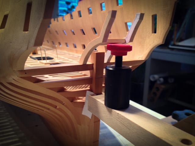
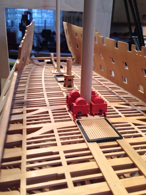
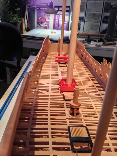
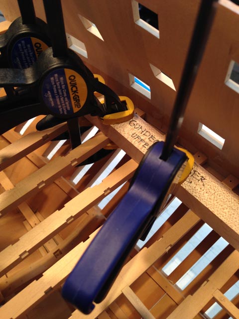
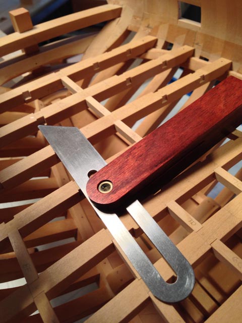
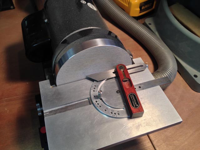
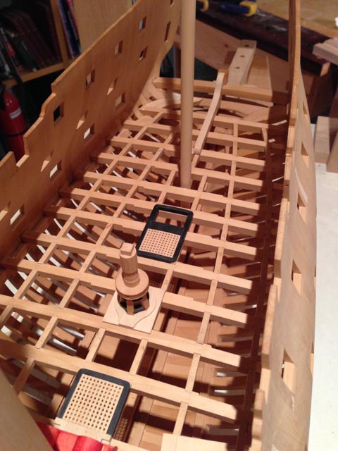
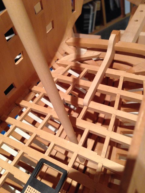
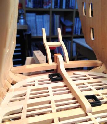
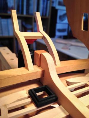
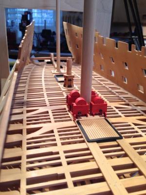
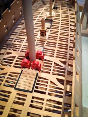
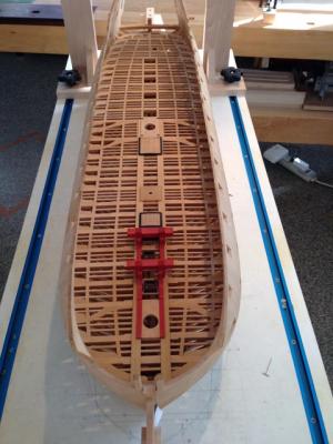
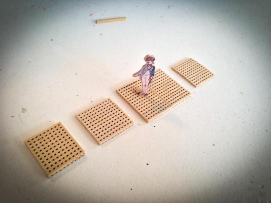
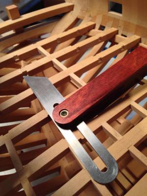
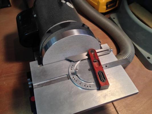
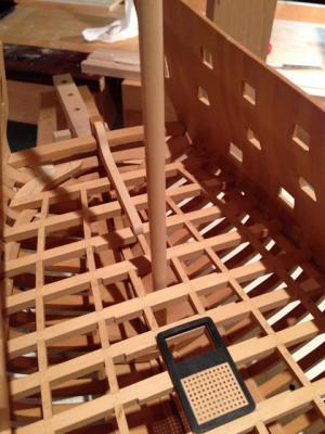
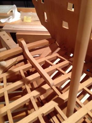
Hi everyone, This weekend, I pushed along to finish the aft end of the gundeck (all but ledges). The first photo shows using a caul shaped to the fore and aft camber of the gundeck, which I used to level the beams as I glued them in place. Clamping the beams up to the caul ensured that they are all precisely level on the upper surface, where it counts. I then worked on the carlings. I found an easy way to measure the angle of the end of each carling in a beam, with an angle gauge. i could then use the gauge to set the angle of the miter gauge on the sanding machine, for precise results, and flip it over to reverse the miter gauge and sand the symmetrically opposite carling in the same bay. Systematically working aft and from outboard to the center, I got them all done in a day. I still need to cut mortises for ledges in the carlings before they can be glued. I got progressively better at this as I worked along. The carling fair well fore and aft, with only one joint needing a slight adjustment from my original mortise cuts. I also built the mizen mast core in anticipation of building the partners, and found an easy way to set the diameters at the 4 quarters, using a proportional divider set to two divisions. I set the long legs on the ruler for the total diameter at any point, and then used the short legs to mark off either side of the center line. It saved a lot of time. I made the fore and aft standard fitting up against the wing transom and stern post. It took some fiddling to match angles and cut the slot for the wing transom. But very satisfying after all of these years to see that finishing up the aft deck. You can see on the starboard side of the aft gun deck, my first efforts at working out how a knee would finish up the deck at the rounded aft end. I have no drawings that show what this knee would look like but there has to be one to provide a landing for decking in the corner, before the decking can land on the deck transom. I can't believe that the decking would just land on the inner side of the aftmost frames with no support under it. Does anyone recall seeing a drawing of what happens here? Best wishes, Mark


-
Thanks, Grant and Greg. The Starrett wiggler turns out to be a hugely time-saving device. I bought one with a couple of attachments. The center finder is a fine point that you align to perfect concentricity by pushing against it with a piece of wood. Go too far, and it flips out and runs in an oval. Push again more gently, and it comes to concentricity again. Once running perfectly, you can align it visually over a center point or a center line. Another attachment has a very fine disk at the end. I used that to center the rotating table. Run it up against one side of the hole in the middle of the table, until it is running concentrically. Note the location on the digital readout. Then run it against the opposite side of the hole until it is concentric, and note the digital readout there. Subtract the one from the other, divide by two, and move the table by that distance. Do the same thing in the other axis, and the center of the spindle is now perfectly aligned over the center of the rotating table. Slick! I also have a Starrett edge finding device. It works great, but in my recent projects I have left blanks a little wide so they can be planed down to perfect size later. It works just as well to locate the center line of a blank with the center finder, and let the edges be wherever they are. Mark