


dvm27
-
Posts
2,404 -
Joined
-
Last visited
Content Type
Profiles
Forums
Gallery
Events
Posts posted by dvm27
-
-
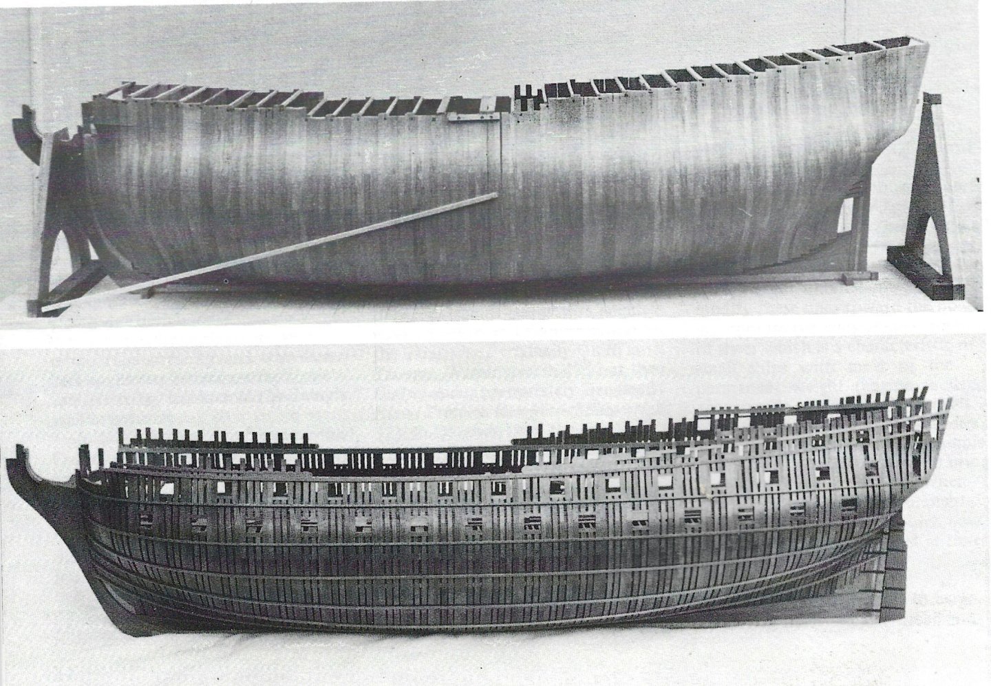
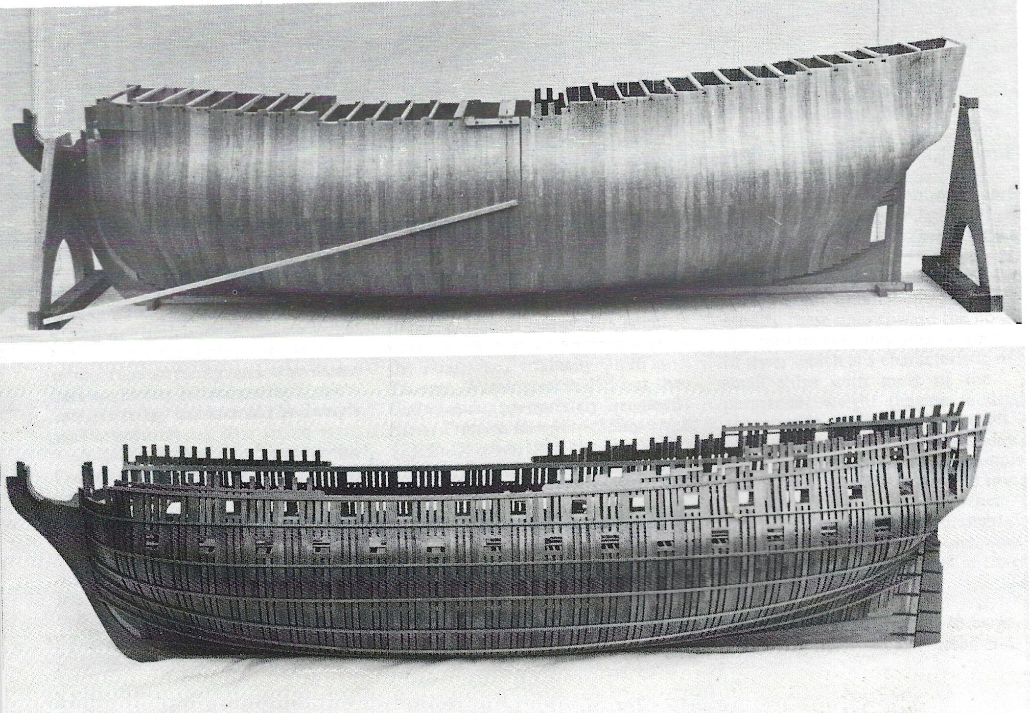
Great job Chris! It looks like those frames should fair in nicely. Your photograph reminds me of the famous Egmont model by John Franklin (Model Shipwright series) in which he assembles, fairs then separates the solid hull and reduces the frames to achieve the Navy Board appearance. His method is not commonly used (except by miniaturists) but seems to have many advantages over the way we currently build them.
-
-
It's looking great Clare. I found her sister, Speedwell, very easy to rig. As I recall the Wolf rigging plan provided was very good. As well, you can find excellent rigging instructions in our Speedwell, Vol. 2. She does have a rather nice lofty rig so your display space will need to double perhaps.
- druxey and hollowneck
-
 2
2
-
I think silk rigging looks beautiful and I know many of the Navy Board models were rigged this way. I have also seen silken robes from previous centuries and they look fine (perhaps because they are preserved in a museum). But I now read that while silk can survive decades they start to deteriorate through a process called "shattering" (the short cross threads become unwoven) at around 60 years. Perhaps this appears in garments only and not laid up rope? But I am fairly certain that no restorer in 2300 will be able to replicate Johann's magnificent work here if the rigging starts to deteriorate.
-
Spot on Chris. The rabbet transition is particularly well executed!
-
What a delight it was for David Antscherl and myself to stumble upon this model after the NE Ship Modelers Conference. I have his books but the model in person is even more impressive. I wonder what Ed is up to now?
-
Do you need to deal with laser char between adjoining pieces?
-
-
Nice video on blackening Kevin. Some random thoughts - I use either alcohol or acetone as a degreaser. Also, keep in mind that brass is an alloy and, depending on the composition, some brass is much more difficult to blacken. For large groups of pieces I find that pickling first makes a difference in the blackening and uniformity of the finish. For small pieces you can use a paint brush to polish them in a deep tupperware piece so they don't fly away. Polishing prevents the finish from transfering to surrounding pieces and evens out the finish. Finally, while it's easier to blacken the Swan PE sheet whole don't you find that you still have to blacken the cut edges after removal from the sheet?
- jpalmer1970, KentM, tlevine and 2 others
-
5
-
Is this a prototype build Ben? I don't see a website for them.
-
In our office pharmacy we use a pill counting app on our cell phones. It works great for similar sized pills (or objects). You obviously wouldn't use it for small groups but for packages of >10 it might be a useful app.
- thibaultron, Ryland Craze, Canute and 3 others
-
6
-
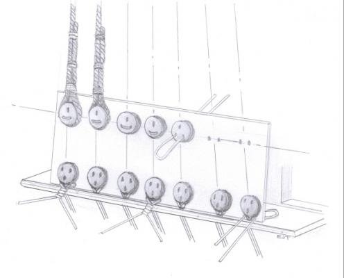
Here's a jig that can be made out of heavy card or aircraft ply. It's not my design but solves the spacing problem between the deadeyes.
- Thukydides, druxey, JpR62 and 2 others
-
5
-
Now that’s a Pegasus! Very impressive Giampiero. I note on the Swan plan and other contemporary figureheads the presence of stippling on the small uncarved section under the belly and legs. I think it adds texture and visual interest. Did you notice this feature?
-
These belaying pins are fabulous! The 1/4" ones are perfectly proportioned and fit a #66 hole. Note - most commercially available belaying pins have very fat handles. Chuck has just saved me hours of work. And adding thimbles to his store would be equally amazing as the commercially made brass ones are no longer available (Crafty Sailor).
-
Your model is very lovely so far. Your concept of rigging the lower yards only with the top masts lowered and mostly derigged is reminiscent of illustrations I’ve seen off these ships in their winter configurations.
Perhaps consider not gluing in the masts. Once you’ve added the shrouds, stays and back stays they are almost impossible to move but minor adjustments may be made by adjusting the standing rigging (just like the real vessel).
- Blue Ensign, CiscoH, hollowneck and 1 other
-
3
-
 1
1
-
3 hours ago, popeye2sea said:
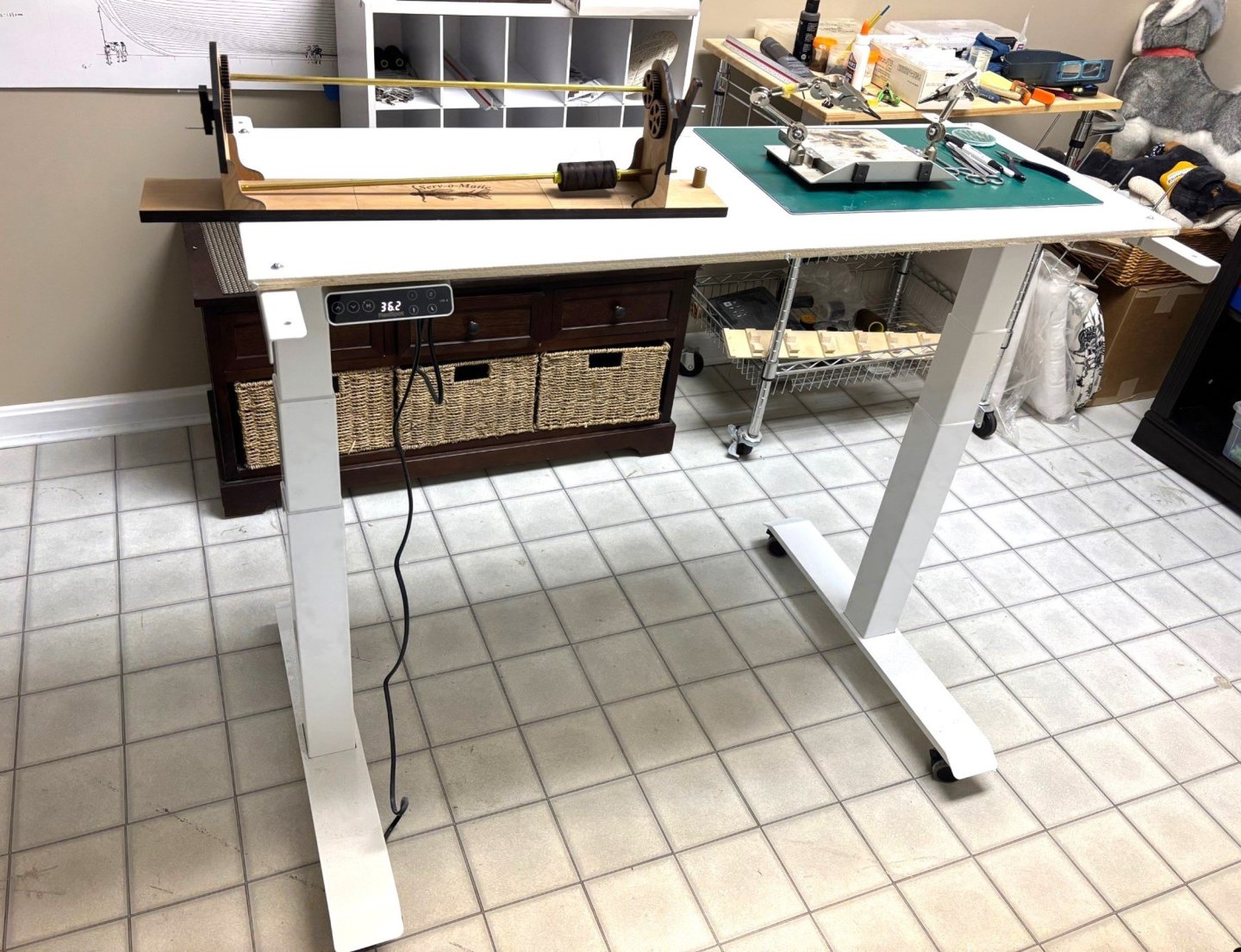
How low do these tables adjust to? It would be nice to have a table that lowers so that working on upper rigging is not such a reach.
Regards,
Henry
Mine goes from 23" to 50". You can set the high and low with a memory button. This will prevent me from impailing my mainmast into a ceiling tile.
-
-
I just bought this FlexiSpot E7 and it's phenomenol. I bought the cheaper version and applied my own top. It is motorized and smooth as silk.
- druxey, Mike Y, Keith Black and 1 other
-
4
-
I'm happy that you've created a new view of Doris's work. Though I suspect shee is done with ship model making her work deserves to be preserved gere forever as a resource. I would hate to lose it if some sort of crash occured.
- Ondras71 and GrandpaPhil
-
2
-
Your work is truely inspirational Johann. Could you have worked the thimbles into the pendants prior to installing them under the shrouds?
- Keith Black, Jeronimo and Jack12477
-
3
-
The problem with such meticulous work is that the joint is barely visible when completed. Lovely work!
- Thukydides, KentM, matiz and 2 others
-
5
-
While watching your video and your bowsprit problem I was going to suggest checking the stieve of your bowsprit vs. the plan. But you came up with this on your own. Your solution worked out well though. You could have worked in a set of beams on either side afore beam #1 but it will be hidden so not really an issue.
You mentioned the "as built home plan" vs the architect's original plan. I'm sure you're aware that many ships plans were labelled "as built" and differed from the original plans as well, likrly for the same reasons.
- AON and Kevin Kenny
-
2
-
Hemostats, by nature, are designed to securely hold and crush tissue for hemostasis. The box section is rivited and there is no way to modify it for a looser grip (that would defeat their purpose). While I've not used them for ship model making you may want to try Doyen intestinal forceps. They have longitudinal groves designed to hold tissue but not damage it. As an example https://universalsurgical.com/product/doyen-forceps/. I think the 7" version might work well for your needs.
-

L'Invention 1799 by Greg Davis - Scale 1:48
in - Build logs for subjects built 1751 - 1800
Posted
Beautiful work fellow Greg. The oscillating spindle sander is one of my favorite tools. I also make extensive use of a mini light box to show the low spots when mating these curved surfaces.