


wefalck
-
Posts
6,370 -
Joined
-
Last visited
Content Type
Profiles
Forums
Gallery
Events
Posts posted by wefalck
-
-
It has been again several months since I wrote something here. However, don’t think that nothing has happened since.
After the funnel I turned my attention to the lower carriage of the 30,5 cm-gun. This is a complex assembly of steel plates connected by L-beams and held together with rivets. Some years ago a detailed Imperial Admiralty plan appeared on the Internet:
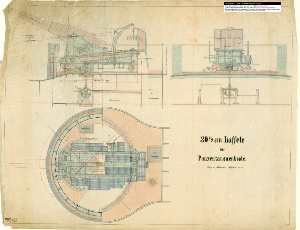
Source: www.dreadnoughtproject.org
Together with the description in a contemporary textbook (GALSTER, 1885) these drawings formed the basis of some reverse engineering. A problem with the above drawings is that many parts are drawing onto each other, semi-transparent and with dashed lines. Sorting out this maze into its three-dimensional element was not easy and some part will remain a matter of interpretation.
I had hoped to get away without etched parts. Trials with embossed styrene-sheet to simulate the rivetting, however, were not very successful. The embossing distorted the miniscule parts. The rivetting is very prominent and can be seen on a large demonstration model in the Naval Museum in Copenhagen or on some russian-kloned Krupp-carriages in the Suomenlinna fortress off Helsinki. The rivetting can be much more precisely rendered with etching and one avoids the added difficulty of having to cut out minute parts.
To begin with the frame of the carriage with sides and ribs from sheet-steel was designed. The L-shaped reinforcement profiles including their rivetting was then drawn. Next in the line was the housing of the training mechanism. I will not fully build this mechanism as it will not really be visible on the finished model. It will be only made in its rough shape that is needed to support the various axles and rods that will be visible. Also designed were the various parts of the hydraulic recoil mechanism and its linkage to the upper gun-carriage. Various other small parts, such as the housings for the sprung buffers that limit the movement of the upper carriage, were designed as etched parts to be folded.
The lower carriage runs on four wheels that are guided by rails that have been turned on the lathe already a long time ago. These ‘castors’ are attached to the underside of the carriage by housings of sheet-metal that have no right angle in them and are set at an oblique angle to the carriage. These parts were developed from the various projections in the drawing above and then checked by printing them as large paper parts.
A lot of work were also the many operating platforms resting on consoles fabricated from L-profiles. Unfortunately, the exact shape and position of the consoles cannot de deducted from the above drawings for all of them. The model in Copenhagen and the originals in Suomenlinna have lower carriages that differ in detail. I will provide two alternatives for the grilles made from wire mesh on the etched fret. The more elaborate version will consist of etched and folded frames with inlays of a very fine steel wire-mesh. If it does not work to cut the wire-mesh to size – some of the platforms are onyl 1.6 mm wide – I will have solid platforms into which a mesh-like structure is etched as fall-back option.
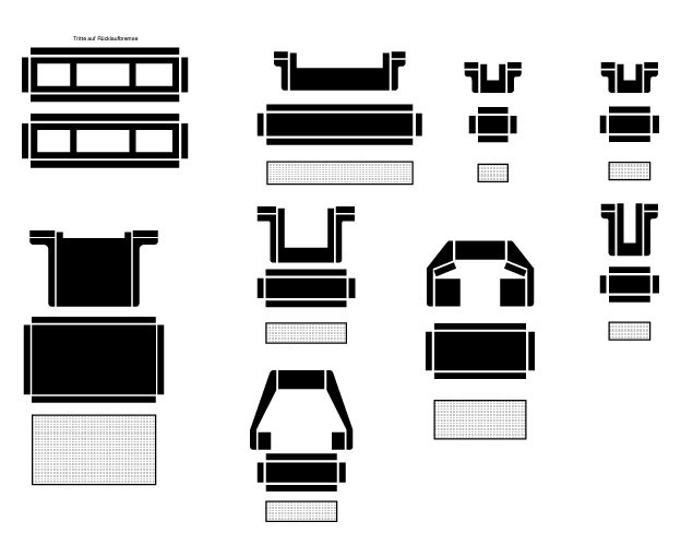
Elements (operating platforms) for etched fret
Also the charging-crane will be built up from several layers of etched part – to get the necessary thickness – and turned parts. The same approach was taken for several other small parts that would be difficult to machine or work on by hand due to their small size, while still requiring a precise geometry.I still have to design a host of other parts that have to go onto the etched fret in order to make it worthwhile to be given outside for having the mask and the etching done professionally.
To be continued soon ...
- Gahm, ccoyle, paulsutcliffe and 8 others
-
 11
11
-
There are many different ways of attaching a sail to the mast. Dutch ships often used a continuous rope running through eyelets in the sail and then around the mast. This is a rather old-fashioned method actually. In order to make the sail run down the mast more easily when lowering the gaff, wooden 'pearls' or klotjes were added.
-
In the monograph on boeiers cited above, there is a cross-section of DE SPERWER which shows the massive floor-timbers, but only some pretty thin planks underneath. This together with KORTES's drawing made me conclude that the boat is built on a horizontal plank, rather a vertical keel. As a matter of fact, there are many transitional designs, not only in Dutch boats, between bottom-planks and keels. Bottom-planks tend to be the older tradition that often slowly changes into the now quite ubiquitous keel, but not everywhere, of course.
The tapering is presumably due to the fact, that they want a pretty wide portective plank in the middle, but then have to somehow lead this into the stem- and stern-post.
-
Very nice woodwork !
Just a little point: DE SPERWER, like many of these boats was not constructed on a keel, but on a fairly wide and thick bottom plank, hence such boats were called platbodems in Dutch. If you check on the drawing in your first post, you will see, that what appears as a keel really is only a thin plank that is nailed to the bottom for protection. Perhaps you should take away a few milimetres from your 'keel'.
There are other boeiers, however, that were built on a keel. The platbodems were mainly built for tidal waters, where they could then easily sit on the mud at low water, while a boat with a keel sails better, but leans over, when on the mud.
- Keith Black, BETAQDAVE, KORTES and 2 others
-
5
-
There is no 'best' - it depends on what kind of look you try to achieve.
Unpainted wood on working sailing ships was either treated with Stockholm tar or linesee oil, or some concoction that contains either or, or both of these. The surface will have a light sheen or be matt, depending on age and exposure of the treatment.
From the late 19th century on yachts (and some high-grade passenger ships) would have unpainted wood varnished. Surfaces would range from satin to high gloss. The varnish would form an appreciable layer on top of the wood, unlike the Stockholm tar or lineseed oil that would soak in.
Many models prefer (it also seem to be a sort of convention for 'historical' models) an 'artisanal' look to their models, highlighting their woodworking etc. skills, rather than representing the actual look of the ship. For this any kind of surface treatment that is used in fine joinery can be used.
For the latter kind, my preferred method is to apply nitrocellulose-based wood-filler and rub this down with very fine (0000) steel-wool. This give a satin finish that deepens the wood colour without forming an appreciable layer on it. For small parts or carvings, one may prefer (diluted) shellac without filler, so that it doesn't clog up the details. Be sure to blow off any slivers of the steel-wool or otherwise you may get rust stains some time later.
- Canute, mtaylor, paulsutcliffe and 1 other
-
4
-
Ah, then you meant southeast not southwest ... well it is relative, we were looking from the Netherlands.
-
Normally it is not so good to show (modern) models to illustrate matters, as one never knows, where the modeller got his wisdom from, but all the pictures I have of mast tabernacles a cluttered with ropes and other stuff, so here is picture of my Zuiderzee-botter model in 1:90 scale:
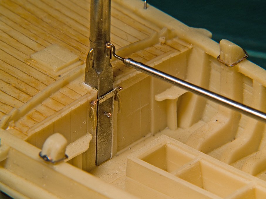
Here the mast tilts forward, so one didn't need to cut out the 'coffin' in the forward cabin.
P.S. perhaps one should rather ask ?dondé? 1500 km (as the crow flies) from Enkhuizen gets you to somewhere in the middle of Spain or so ... didn't realise this before, but the morion in his avatar also suggests that region ...
- BETAQDAVE, Keith Black, mtaylor and 1 other
-
4
-
Clever and beautiful solution ! I think in the old days they just nailed a couple of pieces of sheet-metal on each side.
-
Most, if not all Dutch traditional sailing-boats had their mast installed in a ‘tabernacle’, that is a sturdy two- or three-sided frame. The mast rests in a spur and is locked in place with a latch. To lower the mast, one opens the latch, lifts up the mast a bit and then lowers it. In other, more modern arrangements the mast pivots around a bolt in the top of the tabernacle and is locked in place with another bolt at the foot.
For this reason the boats had a minimum of standing rigging that also could be easily unhooked.
This arrangement was needed because of the many low bridges along the waterways. Some could be raised, but they charged a fee for this.
-
-
-
I tried to use paper - because it so easy to work with and doesn't make a lot of dust - for a steel-ship, but even when soaking it in woodprimer, I found that the crisp edges needed were not possible with this material. However, I think for 'old-time' wooden ships it is a very suitable material, if one does not work in too small scales.
- thibaultron and mtaylor
-
2
-
Paper is a very versatile building material - when you get away from the classical cut-out paper modelling. Your model is quite a tour de force, showing what can be done ! We had seen this already in your article in our journal LOGBUCH 👍
-
Didn't see the building-log until now - excellent progress and excellent work !
DE SPERWER is preserved in the Zuiderzeemuseum in Enkhuizen/NL. Here you can check out various detail pictures that I took of her, when I lived in the area for a some years: https://www.maritima-et-mechanika.org/maritime/zuiderzee/zuiderzee.html
She has an interesting history. She was built as yacht from the beginning, while boeiers were sort of representative boats for well-to-do people in a country when there were not many roads and no motor-cars. Kind of Dutch Mercedes of the 19th century. They were also used as kind of long-distance taxis or inspection boats. DE SPERWER was owned by a certain Merlin Minshall, an adventurer, who worked for British intelligence during WWII, where he met Ian Fleming, who partially modelled 'James Bond' after him.
There is a monograph on the boeiers, albeit in the Dutch language:
VERMEER, J. (2004): De Boeier.- 528 p., Alkmaar (De Alk & Heijnen Watersport).
BTW, what part of the World are you from ? I seem to see some kind of Dutch/Belgian/Northern French houses through the window in one of your pictures ...
-
Well done ! What's the radius of it ? Just to get a better idea of the scale.
- aviaamator, Valeriy V, lmagna and 4 others
-
7
-
Nice metal-work ! How did you do the bearding/rail on the sponsons ?
- paulsutcliffe, Canute, lmagna and 2 others
-
5
-
Yes, that PROXXON is a nice little machine. If it was mine, however, I would replace the revolving plastic handles on the cranks with fixed ones made from some polished metal - gives you much more positive feel of what you are doing, when you are cranking. I even would see to replace them with ball-handle cranks.
- Canute, michael mott, mtaylor and 1 other
-
4
-
This is another case, where modelling habits and conventions are difficult to eradicate, possible perpetrated by kit-manufacturers as well. The worst thing are raised nail-heads, like rivets. If anything, there should be slight depressions caused by the nails pulling the sheathing into the underlying layer of felt.
There are many pictures of real ships with (restored) metal sheathing on the Web now. It is, however, good to see what the contemporary sheathing would have looked like - apart from the colour, which is due to oxidation in the atmosphere.
- coxswain, druxey, pontiachedmark and 3 others
-
6
-
-
Seems that the Chines make quite reasonable ones at a reasonable price - some of my colleagues have been quite impressed. This offer is from NL, but it originates in China. It bit of searching on ebay should turn up an offer closer to home:
-
I think the question was what to do with the lines that attach to the sails, if the sails are unbent. Those lines that attach to the lower corners of square sails are often hooked together, forming a sort of triangle in mid-air. Clew-lines have a figure-of-eight knot made into their end and let run up to the block, ready to be re-attached to the cringles in the foot of the sail, when it is bent.
- druxey and thibaultron
-
2
-
-
That's the trouble of working at such a large scale: you can/have to represent all the details, but things are only an eighth of size ... 😏
Good job on the 'leathering' !
-
A foot control is a good idea for any power-tool in the workshop. I run all my machines off foot-switches, of the momentary kind, i.e. when you lift the foot, the current is interrupted immediately. Keeps your hands free for the work and if something goes wrong, you just lift your foot from the pedal. As I have it in front of the transformer for hand-held tools, it also saves energy, as the transformer is not running all the time.
- aviaamator, pontiachedmark, Canute and 2 others
-
5
Bristol Pilot Cutter by michael mott - 1/8 scale - POF
in - Build logs for subjects built 1851 - 1900
Posted
Very nice sheet-metal work on a type of vents that was new for me. The real challenge for me would have been the making of the hollow hardwood formers ...