


wefalck
-
Posts
6,421 -
Joined
-
Last visited
Content Type
Profiles
Forums
Gallery
Events
Posts posted by wefalck
-
-
-
Excellent ! Are you clenching the nails over the copper discs ? Not sure what the original technique was, but as the rest seem to be pretty much according to prototype, I assume that this is what you do.
- Elijah, Mirabell61, Omega1234 and 1 other
-
 4
4
-
Saludos,
unfortunately, my written Spanish is rather meagre, but I can read it reasonably well
 Interesting project and good workmanship !
I also like the miniature desk-top belt-sander you fashioned from the Proxxon hand-held belt-sander. I have been thinking of a similar project.
-
I gather the fibre glass matts are there to take up the strain from the wood in changing humidity and prevent the surface from cracking. Resin alone would not be able to take up these strains.
Still I was wondering, whether some good marine varnish wouldn't be sufficient because the planking is on some composite board that should take up the strain.
-
-
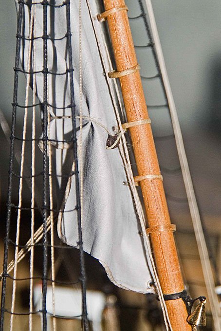
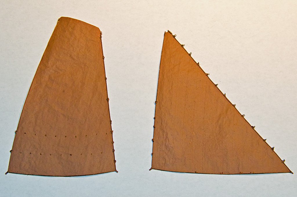
Textile paints - as far as I know - are not meant to close-up the meshes in the fabric. However, this is really what you need to do, because threads and meshes even of the silk are too coarse. At the model scale you just want to have a hint of texture. In fact the silk only acts as a pliable and non-directional backing.
The thicker the layers of paint, the more difficult the furling is going to be and the less 'natural' and to scale it will look. That is why I suggested to first apply a minimum of paint and then, after furling, apply more paint, if needed. However, this requires a bit of experimenting. In fact, I believe Viking-age sails were woven from wool, rather than flax or linen, which is not easily available in the North (but may have become available through trade routes from Rus or the Baltic areas). This may be good news for model representation, as you would have a rather coarse fabric.
When painting the sail you can give it also more plasticity by applying shadows and highlights - just as figure-modellers do to depict fabric. You may want to consult related Web-sites or fora.
-
Do you mean a 'furling' sail, or a 'furled' sail, i.e. is it a static model, or do you want to move the sails ?
If you use the silk mentioned as a basis and give it a thin coat with diluted acrylic paint to close the 'holes' in the fabric, it stays reasonably flexible and can be furled before(!) being really painted. A too thick coat of paint may come off. However, this may require some experimenting. I would also paint the two different colours as base-coat before furling in order to see, where the separation line between the colours will be.
Constructing the sail from individual panels could be difficult then, as the 'seams' would not be very strong and my come loose when furling. However, I have done this (individual panels) also on the model in 1:60 scale below and they furled reasonably well. I had some problems with the bolt-ropes though.
-
I always had a weak spot for those mahagony run-abouts since I was a small boy and went down to the boat-yard at Lake Constance (Germany), where my grandfather kept his wooden dinghy with a small outboard engine - and where a couple of them were moored under a wooden roof for protection. I loved the sound of the heavy engine, when they were taken out occasionally by their (rich) owners.
Missed this building log until today. Nice job !
-
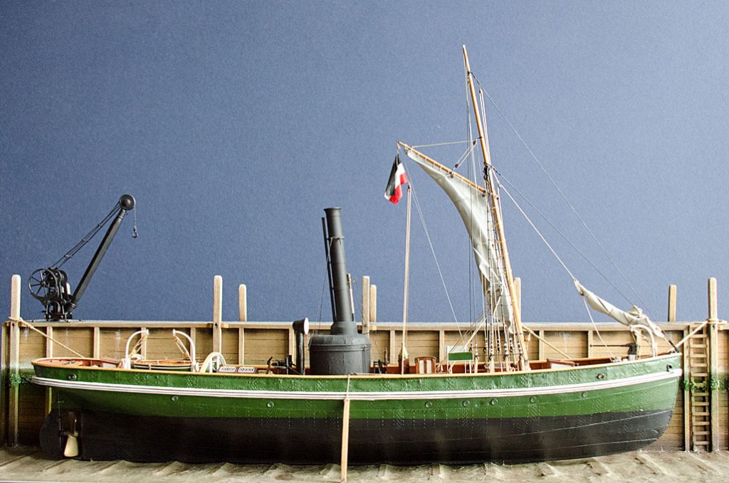
According to an old textbook on marine engineering (Steinhaus, 1870), antifouling paints were available at that time in a variety of colours, including reddish brown, green, black, white, yellow, and blue. Basically, you just add the pigment of your choice. Their biocide effect was based on inorganic lead and in particular copper compounds. Concerns over heavy-metal contamination in harbour muds and the search for a higher efficacy led to the development of tin-organic compounds. However, these are being phased out since the 1990s, when it was discovered that they act as 'endocrine disrupters', meaning that they lead to malformation in aquatic animals that come into contact with them. The problem is that antifouling paints not only act toxic to things that want to stick to a ship's bottom, but slowly wear off (which is part of the antifouling process) and become dissolved or settle in particles in marine sediments. Here their toxic or endocrine disruptive actions continue. I believe in more recent years antifouling paints put more emphasis on non-stick properties and slow wasting that detaches whatever tries to held a foothold.
I gather red(dish brown), green, and black were generally preferred colours, because these resemble the appearance of either coppered or tarred ships bottoms. Muntz-metal bottoms would have looked yellowish to green-greyish, depending on their age. The Austrian navy actually used a pinkish paint on their iron and steel hulls before WW1, btw.
Appart from being a waste of money, paint may not stick very well to copper because of the oxide layer that forms rather quickly on its surface. The picture in the first post is not very clear and I don't know anything about the vessel in question, but would it be possible that a protective sheathing of wood was applied on top of the coppering for travelling in areas where there was floating ice ? This sheathing in turn may have been painted.
-
You know, many of us may have had similar thoughts, but never comitted them to the WWW ...
- Canute, Robin Lous and mtaylor
-
3
-
I used UHU hart in my youth, but then got away from it, thinking that it is a close relative to their original UHU Alleskleber (general purpose cement), which was frowned upon as being not a serious technical glue.
However, UHU hart is based on cellulose nitrate with some ester as a solvent. Cellulose nitrate actually is one of oldest plastics and not based on mineral. Originally invented to replace ivory in billard balls its main use became film materials. Dolls, table-tennis balls and a variety of other consumer products were made from it. It was phased out as film material in the 1950s already, as it burns easily.
A technical summary of UHU hart can be found here: http://www.uhu-profi.de/uploads/tx_ihtdatasheets/RS674_Technisches_Merkblatt_tds_hart.pdf
It is in German, I couldn't find an English version.
In the meantime, I found out that UHU Alleskleber consists of poly vinyl acetate with some ester als solvent. It stays more less rubbery for decades, as oposed to UHU Hart, which becomes hard and somewhat brittle. For some decades now I have been using UHU Alleskleber to glue the metal edges onto my glass-cases. It seems to be less messy than clear silicone.
One problem with glue/cement in tubes is that due to the vapour pressure of the solvent it has the tendency to squirt or run out of the tube, even if you don't squeeze it. I always store my tubes with the tip upright, which largely eliminates the problem and loss of glue.
- Canute, mtaylor and Robin Lous
-
3
-
-
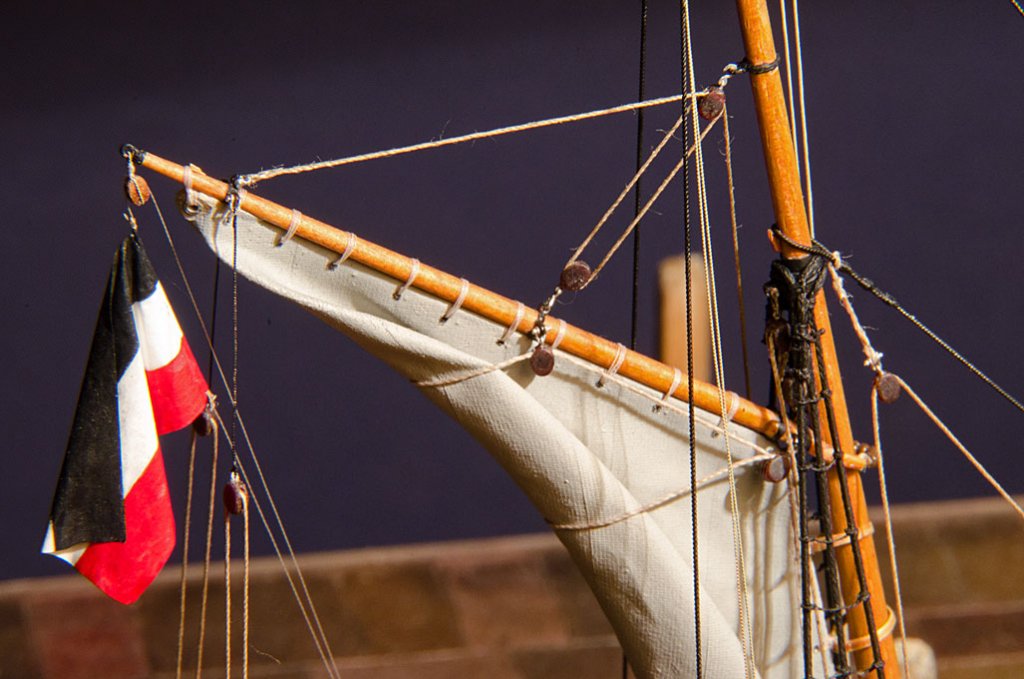
It is a question of scale and what the base material is going to be. Real fabric is not really suitable except for the largest scales, say 1:20 or above, due to too coarse weaving and thick threads.
Personally, I would go for either the silk fabric that is/was used in model aeroplanes or fine paper. Both can be stabilised and shaped using diluted white glue or thin lacquer. They then can be painted e.g. with acrylic paints.
Below is an example from my own production (in 1:90 scale):
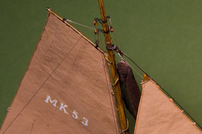
The sails are put together from individual panels. I gather something similar could be done for your sail and the panels painted in different shades of red (ochre). What is the latest research on Viking-age sails ? I am not up-to-date there, but believe that at some stage diagonal panesl were discussed and re-inforcements with leather stripes.
- Bill Tuttle, bhermann, AON and 4 others
-
7
-
I believe all ships sailing in Chinese waters up to the end of the 19th centurey had to be armed at least for insurance purposes. However, it seems that many captains/crews preferred not to put up a fight with the pirates, if they could not out-sail them, because then, in case of capture, the Chinese pirates would then just kill them. If they didn't put up resistance, there was at least some chance that the pirates would let them go. I recently read an account of a German vessel of around 1860 that got captured: the crew was put into one of the ship's boats and set adrift; when they landed on an island in the Chinese sea, the friendly natives stripped them of their clothing, this being the only thing they still had; eventually they were rescued. This lead to a German navy presence in the Chinese waters.
The pirate problem has never been resolved completely in these waters and as we all know, it is now a serious threat to shipping in some parts of the Indian ocean, resulting in commercial ships being armed again.
- mtaylor and thibaultron
-
2
-
Hope you landed safely

***********************************
A while ago I had been able to purchase at a good price a 'left-handed' Lorch, Schmidt & Co. cross-slide, which is what was needed for this project. In Germany, watchmakers for some reason traditionally worked with the headstock to the right, and not to the left as is common practice in virtually all other lathes. Some older watchmakers still seem to work like this, but I gather the majority nowadays, prefer to have the headstock to the righ. In consequence, cross-slides that are meant to be mounted to the left of the headstock and operated mainly with the left hand are relatively cheap to come by.
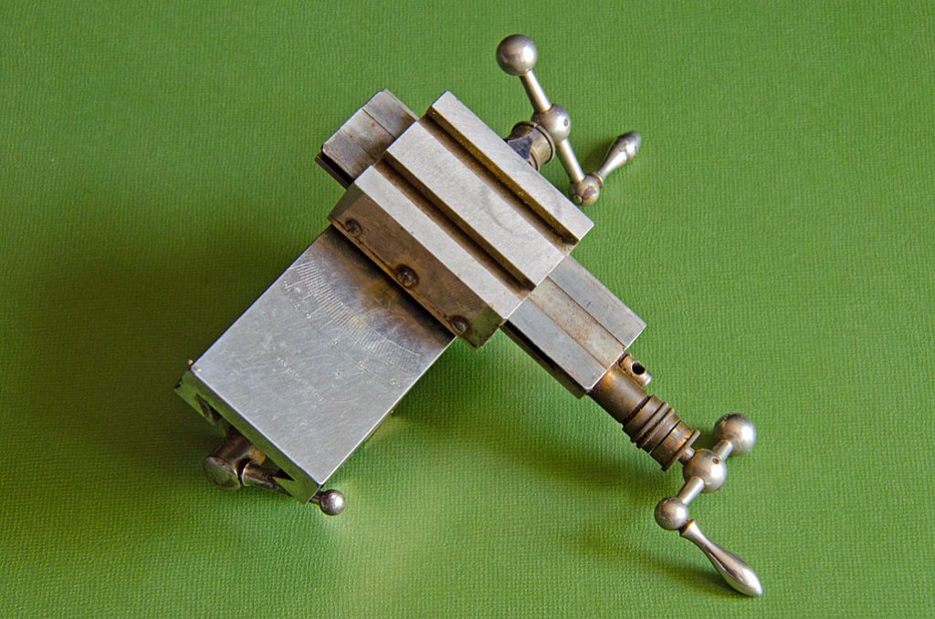
Actuall a right-handed cross-slide but the used was in similar condition (forgot to take a ‘before’ picture)
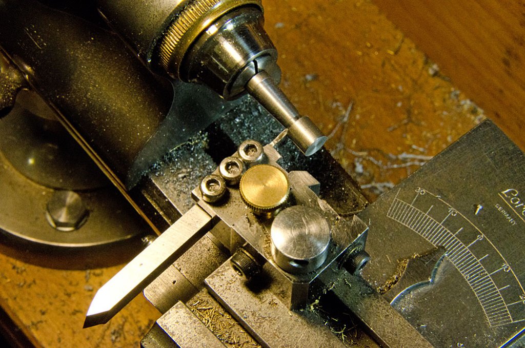
The one I received looked a bit worn on the outside, but mechanically was still in a good condition. Spindles and spindle-nut were tight. However, the nickel plating was chipped and peeling off. I completely diassembled the cross-slide and ground-off the remaining nickel with fine wet-and-dry paper and polished the surfaces. Then all parts were thoroughly cleaned.
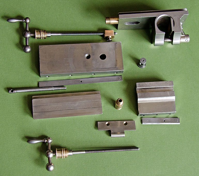
Cross-slide taken apart
The spindles have the 0.75 mm pitch commonly found on cross-slides for D-bed lathes. Not very convenient for calculations, but I got actually used to it on my D-bed lathe. The dial on the y-axis (the future z-axis of the mill) was actually graduated with 15 divisions, giving the diameter reduction when turning, though it has the same pitch as the x-axis. On the mill this graduation would be confusing and I also wanted to have a conical dial on the z-axis. So I moved the x-axis dial to the y-axis, which is the future x-axis of the mill, and made a new dial for the future z-axis.
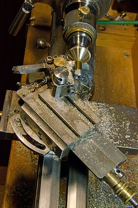
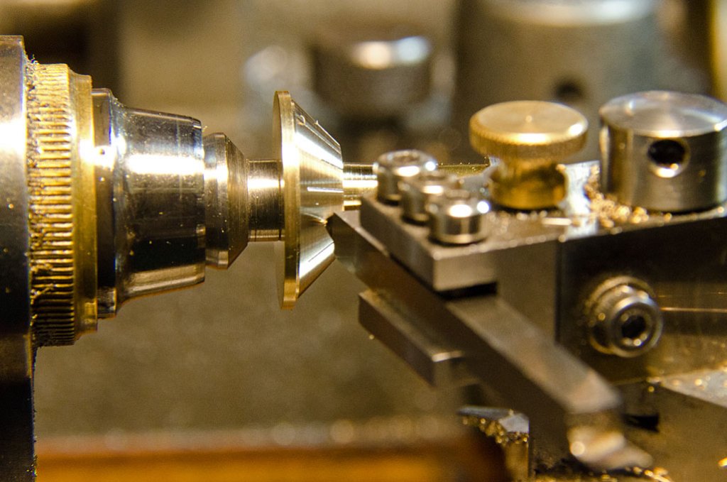
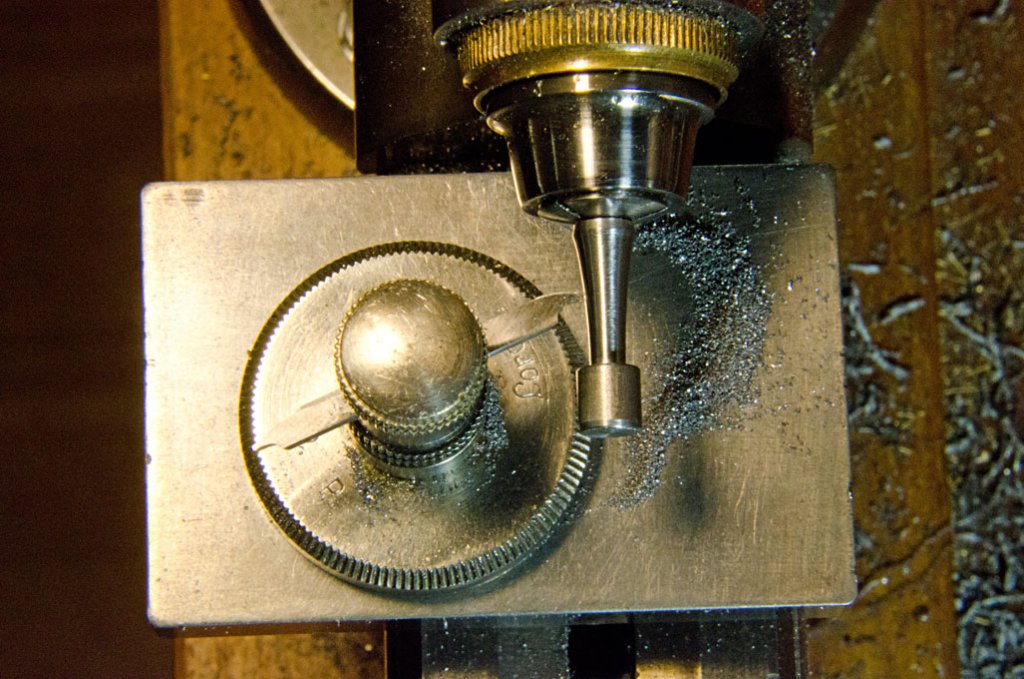
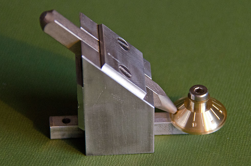
Taper-turning for the new cross-slide dial
For this, a 20 mm piece of brass was drilled and reamed for the 4 mm-spindle. It was then taken onto a 4 mm-arbor for further machining. The lathe top-slide was off-set by 45° for turning the conical shape. In the same set-up the lines on the dial were engraved using a pointed tool-bit - the lathe head-stock, as for all watchmakers lathes, can be used for simple dividing. There are 60 stop-holes, which was convenient for the 15 stops needed here.
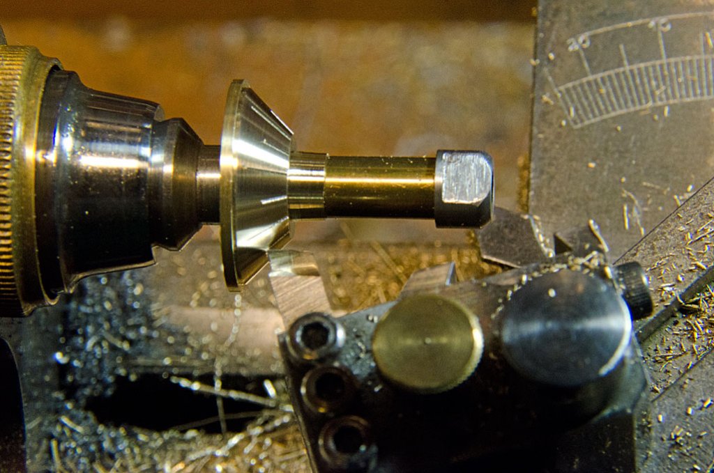
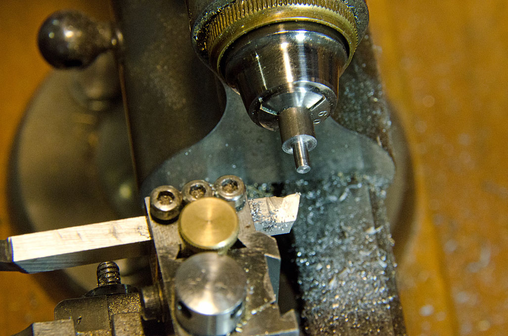
Engraving the cross-slide dial on the lathe
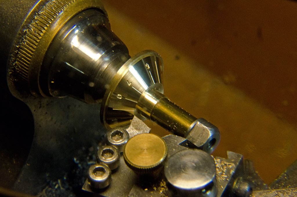
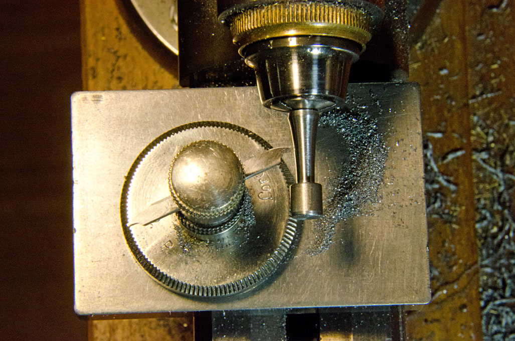
The engraved dial was then moved to a special jig I made some years ago, that allows to punch numbers onto conical dials. After punching, the dial was moved back to the arbor, the exact position had been marked before removal, and the burrs thrown up by the engraving and punching were removed by a light cut, leaving behind crisp lines and numbers.

Set-up for stamping the numbers onto the dial
Cleaning up the engraved dial
To be continued ....
- PeteB, mtaylor, captainbob and 15 others
-
18
-
Yes, I understood the description. However, this means that the burr points against the direction of movement of the stock. In consequence, it would have some sort of cutting action, rather than a scraping action. Cutting means that the cutting edge of the tool is offered to the workpiece with an angle of less than 90°, while when scraping the effective cutting angle is more than 90° (if I got my mental geometric exercise correct).
-
Still wondering about the geometry of the cutting edge. For a card-scraper you would indeed look for something like Figure 3 above. However, in this device the stock is drawn through perpendicular to the plane of the blade, not at an angle as with for the card-scraper. Therefore, a geometry as in Figure 2 seems to be more appropriate.
- captainbob and mtaylor
-
2
-
-
Oh yes, forgot to mention this. There are various hand-tools used in the preparation the teeths for infillings, modelling tools for infillings (ball-ended and other), as well as the multitude of burrs and polishing tools for the hand-held power-drill that are used rather by the dental technicians when preparing crowns, false teeth etc., than the dentist as such.
The UV-hardening glues, I believe, originally came from the arsenal of the dentists.
I am still contemplating getting a dentist's endoscope. Would be good, if they did CCTV-versions, as opposed to those that need to be hooked up to the computer. This would give you a completely new perspective of your model ...
Many of these dental tools now can be bought easily through the Internet.
-
Actually yes, on looking at it, I would have thought that it would work like a scraper. So it actually works more like a flat pencil sharpener then ?
I am actually using tools and instruments from all sorts of 'trades'. In addition to the already mentioned toolmakers, watchmakers, jewellers, etc. tools,
I have raided the sewing-baskets of deceased female relatives and use some of my late father's surgical tools.
Apart from being drafted in as almost finished medical student to serve as assistant surgeon during WW2, he never worked as medical doctor (becoming what is now called a biochemist) and used some of his surgical and anatomical tools in his workshop. There are useful tools, such as solid anatomical scalpels with bone scrapers at the other end, forceps, pinzettes, artery clamps, etc.
My father also had his own hobby chemical and physical lab in the 1930s and 1940s: not sure what he would say to this now, but I used his bakelite optical bench as the basis for my rope-walk.
Old sewing baskets furnish useful rigging tools, such as miniature crochet hooks of a size that doesn't seem to be made anymore, in addition to the wide array of needles of different types and sizes.
The fly-fishing fraternity also has developed one or the other useful rigging tool and materials.
-
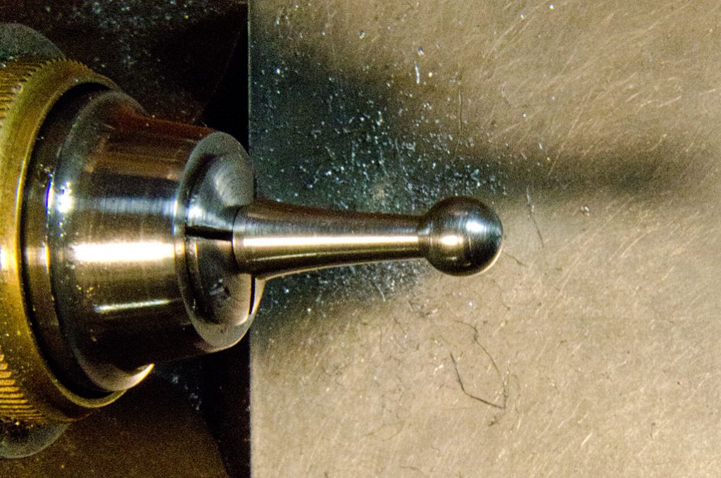
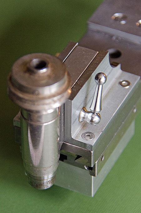
To to continue: The ball-end lever for the locking bolt was fashioned from a short piece of steel in several steps: first the stem that will be a push-fit in a hole of the bolt was turned;

chucking the material with this stem, then the main part of the lever was turned conical, leaving a part cylindrical for the ball-head;
the conical part was given a waist using the free-hand turning rest;
and finally the ball-head was formed using the radius-turning tool.
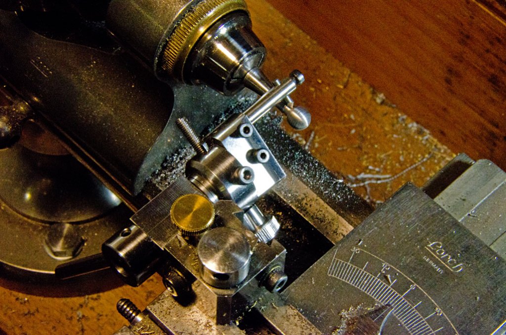
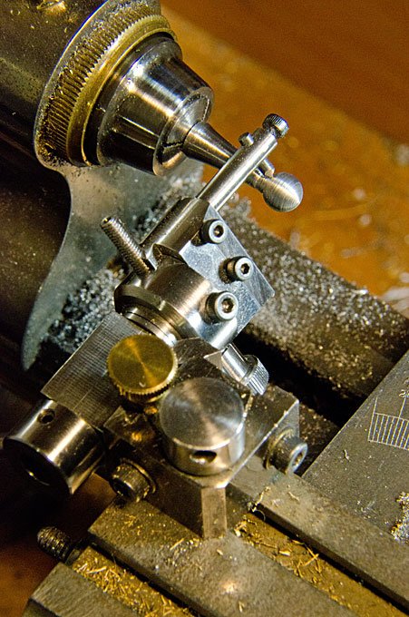
The tool-bit in this case was a 2 mm HSS-bit in a special holder that allows to form a sphere with a sharp edge at the stem.
The finished ball-lever

Ball-lever actuated locking pin in place
To be continued ....
-
Can't help with Elves, but the British OO-scale is nominally 1:76, so there may be something suitable in British railway modellers ranges. Have a look here for instance: http://www.langley-models.co.uk/
British OO-scale white-metal figurines don't have the same standard of sculpting as, say, the German Preiser HO-scale (1:87) hard plastic ones, but some of them seem to be quite nice.
-
A radius-turning tool with a vertical axis would be difficult to implement on a watchmakers lathe, as the clearance over the top-slide is only 7 mm ! So you would need to somehow construct a cantilever from which the turning point would be suspended, or the maximum diameter you can work on would be about 10 mm.
Not sure anymore, whether this was my own inspiration or whether I saw it somewhere in a picture, but I had the idea to use a boring-head, which has a built-in micrometer dial, to change the radius.
I also wanted to be able to turn spherical surfaces for which the centre is not necessarily in the axis of the lathe. Therefore, I built the tool around the quick-change tool-post. Essentially, I built a miniature boring-head and an insert for the QCTP with a horizontal bore, into which the shaft of the boring-tool can be inserted.
The design is not perfect. I should have better control of the end-play in the QCTP and started to work on a system of cone-bearings, but did not finish this.
For the relatively big jobs presented here it works well enough, but when it comes to turning door-knobs and the likes with 0.5 mm diameter, I need to have a better control on the play in the tool.
-
I should perhaps add that I let myself be guided in the desgin of the various bits and pieces by what was practice for these machines. Surprisingly, since the 1880s all manufacturers seem to have followed largely the same designs with only small variations in detail. For new parts I try to imagine how these manufacturers would have made them. However, as I have no possibility to have iron castings made, I have to fabricate parts.


Late 19th Century Merchants: Antifouling Paint Over Copper?
in Nautical/Naval History
Posted
Looking again on the images, I think in the area around the stem one sees copper sheathing. What is a bit strange is the somewhat fuzzy waterline that looks painted on. Perhaps she had a reddish boot-topping ?