


wefalck
-
Posts
6,421 -
Joined
-
Last visited
Content Type
Profiles
Forums
Gallery
Events
Posts posted by wefalck
-
-
Better yards indeed built under a shed, if physically possible. Wood is not 'weathered', that is exposed to the elements on purpose, but rather 'seasoned' in a shed, as noted above. Leaving a ship in frames outside was rather a necessity (lack of funds, workmen, etc.) then a deliberate choice.
- mtaylor, druxey, vossiewulf and 1 other
-
 4
4
-
Not in metres or feet - one has to think in terms of where it can/needs to be fastened. I don't think a plank shorter than then distance between three frames (or deck beams) would be feasible due to alingment and caulking problems.
- Richardjjs, WackoWolf, Mirabell61 and 8 others
-
11
-
-
It may be worthwhile to reflect on the function of the (topping-)lifts. They are there to steady the yard, not to 'lift' the yard, which is done with the halliard. So, when the topsail(s) is/are set, there is no immediate need for the lifts, as the yard is also stabilised by the braces. One can probably let go the lift(s) when close-hauled and the problem is solved.
- mtaylor and Roger Pellett
-
2
-
If you use an acid, such as cooking-grade flavoured vinegar, the coloured compounds will be probably some iron-organic acid complex. If you filter this, there will be no particles. You should end up with a dye. However, big chemical companies can control processes much better and I would also go for commercial dyes. At the amount we need them, the cost will not kill you.
Incidentally, the (cast-)iron guns of old were 'browned' by repeatedly wetting them with vinegar. Finally, the rust and iron-organic compounds were solidified by applying lineseed-oil. Kind of in situ oil-paint production.
- mtaylor, Roger Pellett, Canute and 1 other
-
4
-
Did you mean that they are bevelled ? If that, I would make a sanding jig for this, so that you can hold them at a 45° (or any other appropriate) angle. That jig also should have stop, so that you can offer all sides of the bits etc. at the same distance to the sanding block in order have the bevel equal.
I you have a milling machine, of course, you can also make a jig for use on that one.
-
Fröhlich's tool is hand-held. That's why he needs a female part, to guide the male part ... If you are using the tool in a lathe (or in a press like the one shown above) the machine does the centering and you get away with two - easier to make - male parts. I would use a piece of silver-steel (drill-rod for the North Americans) and turn on in the middle a somewhat elongated circular groove with approximately the radius of the radius of the rope for which the thimble is to be made. The material that is left standing in the groove will have to have the interior diameter of the thimble. You then cut the rod in the middle of the groove, harden it and, voilá, you have your forming tools. Hardening may not even be necessary, as you not going to bang the tool, but just gently push it with the tailstock. You will probably have to experiment a bit with the diameter of the rod and the length of the tube section to arrive at a good shape for the thimbles.
Incidentally, many years ago, when I had no sophisticated tools at all, I made thimbles from very thin cored soldering wire that can be easily flared out. I think I used a rotary burr for the purpose.
-
-
What lathe do you actually have ?
- thibaultron, WackoWolf and mtaylor
-
3
-
-
I believe a lot of the standard iron-work, such as thimbles, shackles etc., that would have been factory-made would have been zinc-plated at that time already, rather than painted black. If you use brass for the parts, they can be chucked into self-tinning solution, which looks quite convincing like zinc afterwards. If you desire such look, you can slightly 'weather' it by rubbing a soft lead-pencil over it.
I gather brass tubing is available down to 0.3 mm I.D. with a wall thickness of 0.1 mm. You may need to anneal the tubing before forming the thimble. Bernard Fröhlich shows in his book a tool similar to the one you are using, but with a punch and an anvil. One can use this on a pillar-drill with a depth stop, or the best choice would be a so-called jeweling-press as watchmakers use it:
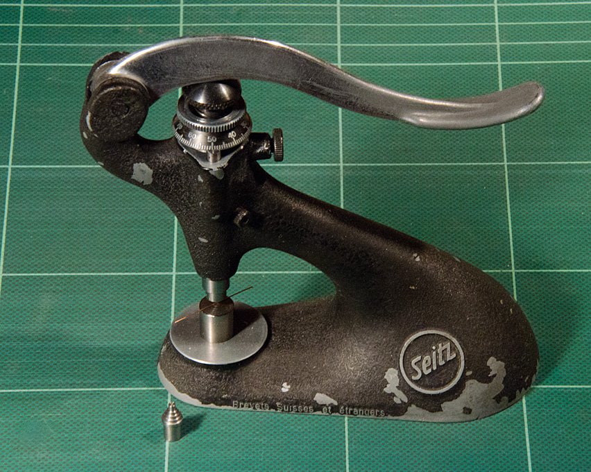
They have a micro-meter depth-stop and are quite cheap to obtain, when they don't have the tooling with it anymore. In our case, we would make the tooling ourselves anyway.
-
I made a rough-'n'-ready sketch of what I meant:
I have made a set of speciality collets myself from blanks purchased from Schaublin some 15 years ago. The difficult step is the slotting one, as you have to hold the collet at its very end and concentric with its axis of rotation. For round collets this is not so terribly critical, as it is mainly the bore that centres the material. However, that is different for the square collets, where the cuts have been absolutely parallel to the axis of rotation.
- thibaultron, WackoWolf, BANYAN and 4 others
-
7
-
Actually, making collets with four slots, instead of the usual three for high-quality ones, was one of the easier routes for holding square stock or parts I have been thinking about. The other possibility with more holding power would be to make four slots that off-centre by the thickness of the targeted stock minus the thickness of the saw blade. The challenge for both variants is to have the slots absolutely symmetric, otherwise the collet runs off-centre.
-
I think Michael uses the right strategy. Starting with slightly oversize stock and working towards the collet keeps the flexing and vibrations to a minimum.
The type of brass is also important. I found most fine brass wires not very suitable for turning and use brass nails instead. Even, if sold as 'half-hard' they are usuall too soft. The reason is that copper and its alloys do not harden by heat, but only by 'working' them. Brass nails/pins are sort of stamped from wire and harden by the process.
It sounds attractive to first drill the holes, while the stock is still thick, but you will have two problems then: a) the interrupted cut, where the holes are, while turning will result in chatter and unclean surfaces,
 the stock is weakend, where the holes are.
Starting with square stock again sounds attractive, but you run into the above two problems, plus the fact that at this dimension and for the type of lathe we use, you will not find square collets. The four-jaw-chuck will not be precise enough for the purpose. This problem has actually been nagging me for years. The only square collets you can get a reasonable price are the 5C-type ones - way to big for my lathes. I have talked even to manufacturers for B8-collets (which is what I need), as with EDM and other modern manufacturing techniques, it could be possible to make some, but too expensive. I am still thinking of making some myself ... but this is digressing from the thread.
- mtaylor, thibaultron, WackoWolf and 5 others
-
8
-
Brass can be cut with zero-rake tools. That's probably, why your broken drill works when ground flat ( which is, I assume, what you did ?). As it doen't have a point, it will not wander. I also made tiny end-mills from such broken drills.
- WackoWolf and thibaultron
-
2
-
-
Actually, we learned this at school ... additive and subtractive colour and light mixing. I remember having to paint various types of colour wheels using the school-box of water colours.
BTW, ochre pigments are not usuall 'made', unlike lead-white, but are mined at certain locations, such as southern France, where the iron-oxhydroxide occurs in a relatively pure state, without an admixture of clays and other silicates such as quartz. The mined lumps are broken down and milled in large calanders (similar to the mediterranean olive presses of old) before being flotation-washed to remove impurities.
-
I have two types of proportional dividers.
The one shown below is a lot more accurate than my mechanical type and faster too.
The accuracy required is not only that of the calculation, but also in the transfer to the work-piece ... how does this happen then ?
- Canute, jud, Seventynet and 2 others
-
5
-
I noted that you further developed your holding gadget. I like the idea of integrating a pin-vice. Also, you got now nice ball- handles !
- thibaultron, mtaylor and hexnut
-
3
-
Hhhmm, just thinking about error addition/multiplication ... using proportional dividers to mark out n equal divisions for planks along e.g. the circumference of a frame requires that you apply the dividers n times, thus likely adding n times an error of similar magnitude, e.g. because the dividers slip a bit on the woodgrain, parallaxes, etc. If you were lucky, you would make as many positive as negative errors, so that you would end up at the desired end-point. You could do the same process from the opposite end again and then middle out the differences. Not sure one gains a lot of time.
Today I think I would take a paper strip and place it around the frame, marking the desired end-points. I would then measure the distance with a vernier caliper and take this measure to my drawing programme on the computer, that has been calibrated agains the printer to give a dimensionally correct print-out. I would then draw a long rectangle and have it subdivided into the necessary equal parts digitally and print this out. The cut-out strip of paper is then taken back to the frame.
Alternatively, if you was to use paper templates for the frames, the subdivisions for the frames can already drawn onto the templates and no additional measuring on the model itself would be required.
There are various other strategies I suppose.
This is not to say that I don't find these instruments attractive as instruments. If they weren't so expensive, I probably would have got one myself already ...
-
-
These ceramic fibre files sound interesting (put rather pricey) and I have not been aware of them. They say that they don't break easily, but I would be so sure about this for say a 0.5 mm x 0.5 mm file. Have to look into this for my filing machine.
Here are the relevant Vallorbe-catalogues on files etc. for downloading. They don't give prices, but show the full programme:
http://www.vallorbe.com/umv/ch/fr-ch/file.cfm?contentid=5154
http://www.vallorbe.com/umv/ch/fr-ch/file.cfm?contentid=5182
http://www.vallorbe.com/umv/ch/fr-ch/file.cfm?contentid=5638
In addition to the japanese slot-files mentioned above, you may also want to have a look at joint- or screw-head slot-files as used by watchmakers. They are in the first catalogue above, but can be obtained from other manufacturers as well.
I also found a lot of useful abrasive tools at the dental technicians' supply houses.
- mtaylor, thibaultron, vossiewulf and 4 others
-
7
-
I can see the uses for it and it may be a nice tool to have for the quality of being a nice tool. However, with computers, pocket calculators, spreadsheet programs, scanners, and (laser) printers around, so far I did not have a real need for a pair. I would rather invest the 100€ into something else ...
-
Actually, if you look at a real ship, there are only subtle variations from plate to plate, if any. Exposure to seawater tends to level out any original variations in the state of oxidation (which due to the fairly uniform and industrialised production process, even in the 18th century, would have not been considerable). So I don't quite understand what the purpose of this rag-rug appearance is. One should also keep in mind that oxidation colours that result from contact with ambient air are different from the colour that develops under water and at the water-air interface. The presence of sulfates and organic substances in seawater are mainly responsible for this.
Rather than using an open flame for achieving oxidation colours, I would use a hot-air soldering-gun, where you can pre-set the temperature of the air-stream and thus have much better control over the process.
? for experienced riggers
in Masting, rigging and sails
Posted
A 'story-board' is always a good proposition for justifying, why certain features are shown. It makes sure that the different aspects, e.g. of how the sails are set, match throughout the ship. Basic facts to consider would be the direction and strength of the wind relative to the ship and what kind of sea it is encountering.