


wefalck
-
Posts
6,493 -
Joined
-
Last visited
Content Type
Profiles
Forums
Gallery
Events
Posts posted by wefalck
-
-
Looking good!
I gather the book on catalan lateen-rigged boat that you got, will give some more ideas on the specificities of that rig. One of these is that the parrel is a sort of rope with an eye at its end that goes around the mast and is fixed to the halliard. The purpose is to be able to loosen the parrel to allow a better adjustment of the antenna. Not sure though, whether this would be case on the more lugger-sail like sail of the canoa here.
On the photo below from the Albufera near Valencia (Spain), the parrel is a pretty ugly affair, not quite ship-shape:
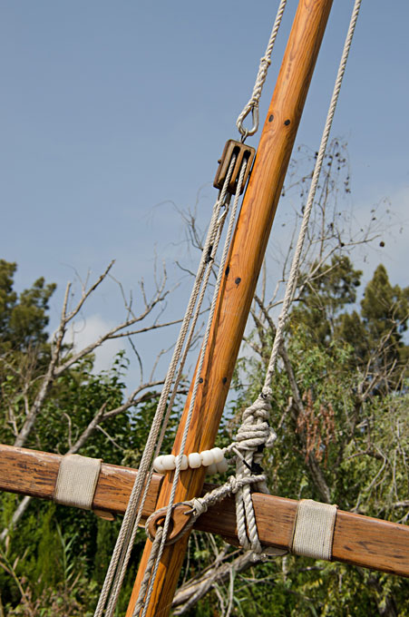
Probably your photographs don't show such detail, but usually the rope that attaches the sail to the yard is not just wound around, but at each grommet there is a half-hitch - I don't have an image to hand that would show this. In that way, the sail has less a tendency of slipping along the yard or pulling out of shape.
-
-
Thanks for the links, have to look into this - just revisted the Sjöhistoriska Museet in Stockholm three weeks ago - one of the last of the maritime museums that really seems to appreciate its model collection.
- mtaylor, Canute, scrubbyj427 and 4 others
-
 7
7
-
-
In Europe it were Norway (NorskHydro) and Switzerland (Alusuisse) that had been the main initial producers, due to their hydropower capacities.
- mtaylor, Valeriy V, Keith Black and 4 others
-
7
-
Hope you don't need to repaint your models now - we were quite happy with the colour schemes of the woods etc.
")
BTW, Gratulations to the successful surgery! I gather it is like getting new glasses: the brain has to readjust the images to the perceived realities.
-
How could I know, that you are working on three projects at the same time ... so I missed the beginning 🙄
Very good subject! I doesn't always have to be a VICTORY cross-section !
I know very well the space and mobility problem.
-
-
Funny thing is that often here on the continent stock sold is not exactly metric, but actually imperial, say 6 mm dowl rod is actually 6.25 mm = 1/4" ... As you have to shape it anyway, the starting dimension just needs to be bigger than the biggest diameter required.
- scrubbyj427, catopower, mtaylor and 1 other
-
4
-
Self-centering 4-jaw-chucks are far and between, because they can and should only be used on square stock or parts. Sherline does offer one of the hobby market and that is the only one I am aware of.
Independent 4-jaw-chucks are very common and are either used for precision centring of round stock/parts with the help of dial indicator or, indeed, for irregular/rectangular/square stock/parts. There are many offers on the hobby market.
Sometimes and particularly in the USA independent 4-jaw-chucks are confused with faceplates with moveable jaws. Chucks, however, are meant to take up longer stock/parts, while faceplates are meant for mounting short stock/parts on their surface. On faceplates the jaws are sitting on the surface, while in chucks the jaws move in T-slotted or dove-tailed slots.
Incidentally, chucks with dove-tailed slots are rather rare today. Normally, either solid jaws run in a sort of douple T-slot or the jaws are in two parts, so that the top-jaws can be reversed or exchanged for other types of jaws.
4-jaw-chucks and faceplates have to be operated with caution, as the excentric load can cause vibrations and light machines to jump around, when not fixed to the workbench.
As far as I remember, PROXXON offers a metal and a plastic chuck for its light wood-lathe. The idea is that with plastic jaws there is less risk of marring the material.
I am curious what lathe you are using that has a 16x1.5 spindle-thread?
-
Museums and other high-end customers may not like styrene, as it is prone to deterioration over time due to the outgassing of the softeners. That is a reason, why I use bakelite paper, there are no softeners inside.
- Canute, yvesvidal, FriedClams and 4 others
-
7
-
To me it looks, as if the boom runs in at deck level. It then could be secured on deck with wooden cleats and a stopper block at the inner end.
- mtaylor and Thukydides
-
2
-
To this one could add, that both, wood and cardboard, need a lot of surface treatment to look smooth like the original metal. For this reason I resorted to bakelite paper, which is available down to 0.2 mm thickness.
-
Anything that allows to work from one set-up is not an 'overkill' and will pay back with peace of mind later 👍🏻
- Ras Ambrioso, FriedClams, druxey and 4 others
-
7
-
-
Good luck, Keith. My mother had it in her late 80s and was very happy with the result.
- Keith Black, FriedClams, mtaylor and 2 others
-
5
-
-
Yep, with a bit of putty and a few tools, one can quite easily adapt commercial figures.
However, 3D-printing in acrylic resins is the future. It may be worthwhile contacting sellers on the commercial platforms, such as shapeways, in order to see, whether they can/are willing to print their figures in different scales. While upscaling or downscaling over a large scale range may not be feasible for reasons of resolution, a change from 1/72 to 1/80 or from 1/87 to 1/80 should not pose a big problem.
- FriedClams, mtaylor, Keith Black and 4 others
-
7
-
Wow, this is quite a price tag for those two tools, even though they look sturdy and well-engineered.
If something melts or burns during machining, that means you are putting too much energy in a too short time-span into it. Reducing the energy helps. If you have a 220V/110V sander, you can reduce its rpms (and hence the energy put into the process) by running it off a dimmer, if doesn't have already a speed control.
I also found that diamond tools work better on plastics (acrylic glass, polystyrene, etc.) than carborundum abrasives, so I am using diamond grinding discs on my micro-sander.
-
The last two weeks were spent travelling on business, to Stockholm (including a renewed visit to the Maritime Museum there 😉 ) and to Brussels. Friday and Saturday I spent at the information desk of Association des Amis du Musée de la Marine, which has been finally re-opened (see other thread on this). So, not much time in the workshop, but I still managed to complete the
Banisters
These banisters are flimsy matters so that I left them to the end as far as possible, still following the pattern to work ‘inside-out’ in order to not damage delicate items.
The information is somewhat patchy as to what the banisters actually looked like. They are represented in the lithographs and on one or the other photograph, one can see parts of them. Basically, there are two types: bend pipe-work and straight stanchions located in sockets that support a wooden rail.
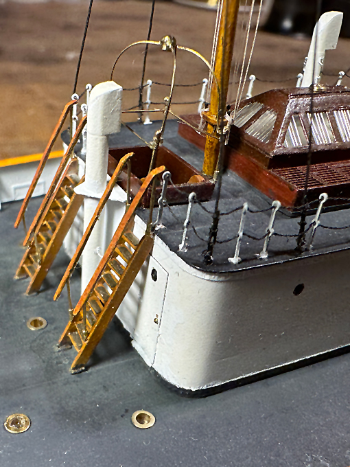
As the metal parts are laid out in yellow on the lithography, they appear to have been made from brass (or bronze). One picture shows bare metal for the pipe-work. Hence, I decided to make them from bare 0.3 mm brass wire. At the moment this looks rather bright, but I assume that it will tarnish somewhat with time.
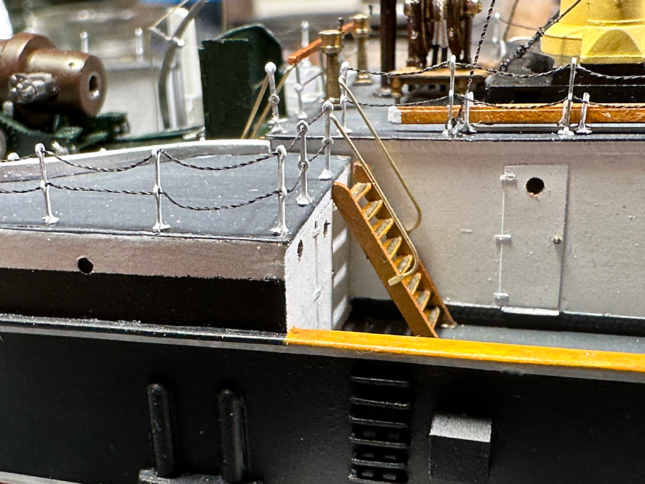
The pipework ones were bent over a scale copy of the lithograph. The ends, where they attach to the stairs appear to have been flattened, which duly was represented on the model.
For the ones with wooden rail at the end of the deckhouse, I cheated a bit and instead of having individual stanchions, I flattened the wire in the area of the wooden rail to have a support for it and bent the stanchions down sharply. The sockets were cut from 0.5 mm OD brass tube, which is a sliding fit on the 0.3 mm wire. The ends were milled down to the appropriate angle. The wooden rail was fashioned from two laser-cut strips of paper laminated together with varnish. With hind-sight, fashioning all parts from brass and soldering them together in a jig might have given crispier results.
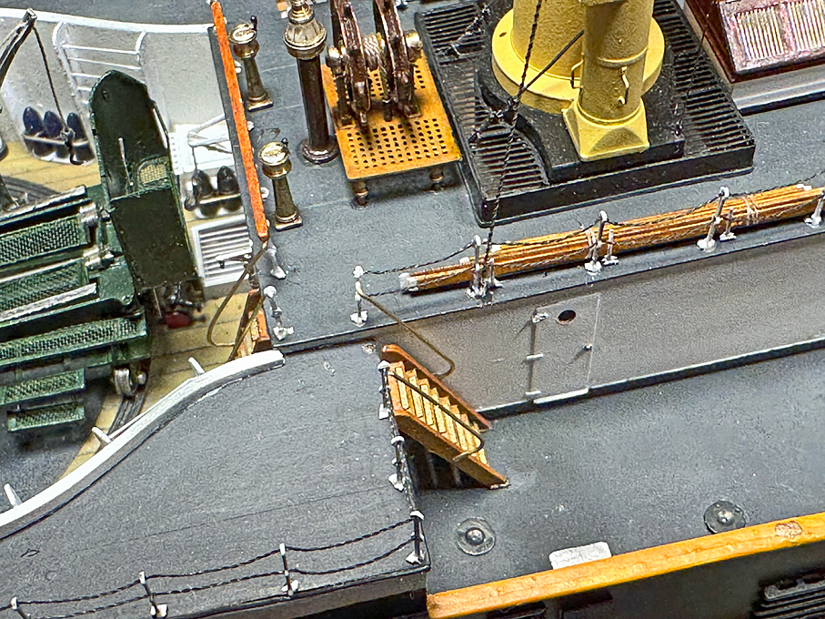
All parts were cemented in place with clear varnish.
Overall, these quite simple parts took surprisingly long to produce.
To be continued ....
-
... however, if you look at period photographs, very few people did wear Holliwood Cowboy-dresses and Stetsons. Bowler hats and the likes seem to have been more common, even in the 'West'.
- Keith Black, FriedClams, Canute and 3 others
-
6
-
The German manufacturer Preiser (https://www.preiserfiguren.de/) used to have a small series of figures of around 1835 (to match a model of the first German steam-train) and a larger one for the period around 1900. They are in HO (1:87) scale and I have not checked, whether these series are still available.
The closest in scale would be the British OO (1/76) scale and there are various manufacturers that make figures in whitemetal for the period around 1900, e.g. https://www.scalelink.co.uk/acatalog/index.html. In terms of quality (animation, detailing, etc.) they don't match the Preiser-figures though, which is partly due to the casting process, I suppose.
The 1/72 softer plastic figures by HäT etc. (see http://plasticsoldierreview.com) are probably on the large side. But in the linked Web-site there is also an assessment of the 'true' scale for virtually all sets reviewed. Civilians though are far and few, as these aim mainly for the 'wargaming' market.
True 'wargaming' figures in whitemetal would be too big and they are too chunky for my taste anyway.
- FriedClams, mbp521, Canute and 3 others
-
6
-
I wouldn't worry about the wood-grain not matching up at the joints. This would be quite common in this kind of craft, where they would have used what was available at the moment.
Talking about woods: mango wood seems to be quite common as building material in certain (sub-)tropical regions. The dhow-builders in Tanzania/Zanzibar, for instance, use it extensively.
Whith this kind of rough-and-ready working boats it is always difficult to strike the balance between precision in modelling and the somewhat rough look of the prototype. However, poor workmanship is difficult to sell as the rough look of the prototype ... the 'roughness' has to be also to scale.
-
On 11/6/2023 at 7:47 PM, Retired guy said:
Hi Keith now have painted the chain but before I did I filed the chain down a bit and now it looks a lot better.
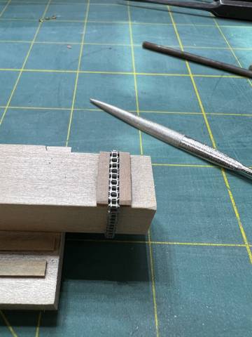
Does this mean that you filed to shape each individual link? I also noticed in your building log, that you shaped by filing the straps for the dead-eyes. Do you use some kind of template (like the file-buttons of ancient mechanics) or is it all free-hand? How do you hold these tiny and narrow parts during filing?


Help for blocks with hoop required.
in Masting, rigging and sails
Posted · Edited by wefalck
You don't mention the scale, but it is possible to make simplified long-splices by pulling the ends through each other with the help of e.g. a hypodermic needle as marlin-spike. You then dab the splice in varnish and roll it between your fingers. Then you basically proceed with full-scale practice and tie the strop around the block and the ring on the traveller. The splice will disappear under the seizing.