
HOLIDAY DONATION DRIVE - SUPPORT MSW - DO YOUR PART TO KEEP THIS GREAT FORUM GOING! (Only 13 donations so far - C'mon guys!)
×

glbarlow
-
Posts
4,107 -
Joined
-
Last visited
Content Type
Profiles
Forums
Gallery
Events
Everything posted by glbarlow
-
 Thank you for saying so, but the collection will only be mine I’m sure. I doubt I could part with it after being so long together with her.
- 778 replies
-
- 1
-

-
- cheerful
- Syren Ship Model Company
- (and 1 more)
-
Thanks Garthog! There’s still more fun to be had and more things to do for the first time, I can’t stop now😁
- 778 replies
-
- 1
-
-
- cheerful
- Syren Ship Model Company
- (and 1 more)
-
Thank you! Me too 🙂
-
Thank you Chuck. I also love the color and tone of the yellow cedar. My focus on detail and willingness to do it over until I get it right is a tribute to your elegant design, instructions, and guidance.
-
I appreciate your saying so.
-
Thank you!
-
Thanks Derek. I’ve tossed and replaced so many things all the way back to planking I feel like I’ve built it twice.
-
I thought about it and replaced the ones seen in the photo with 24 guage wire versions but from clean deck it would go to cluttered deck in my opinion, especially with the rigging to come.
-
You can do this one for sure, but hilarious comment🤣
-
Two posts back to back. Thank you for the comments, hope you also enjoy the completed hull photos.
-
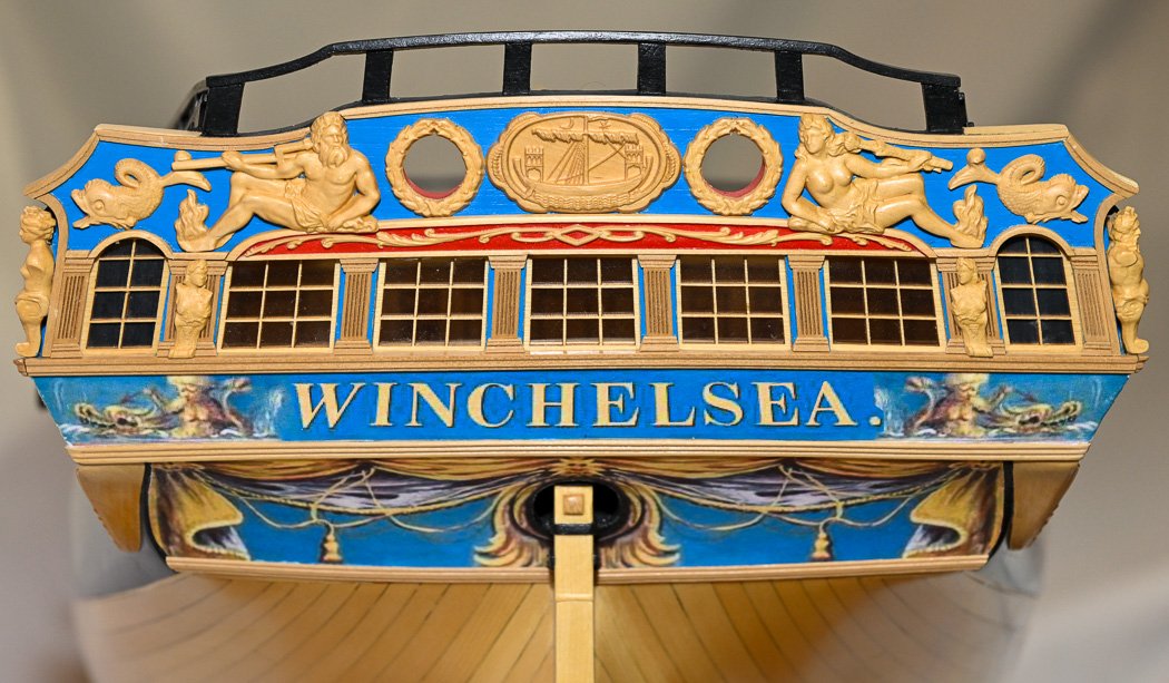
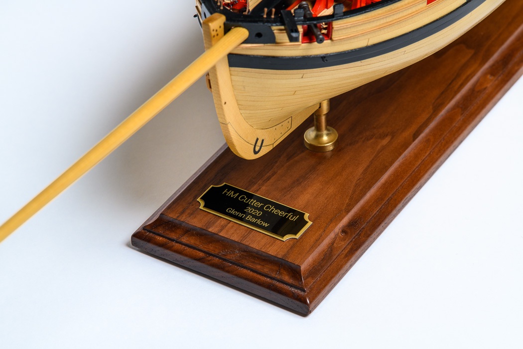
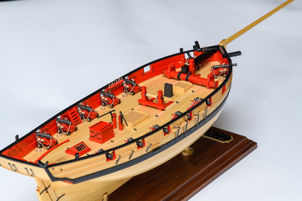
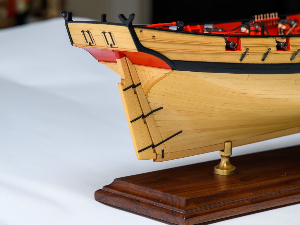
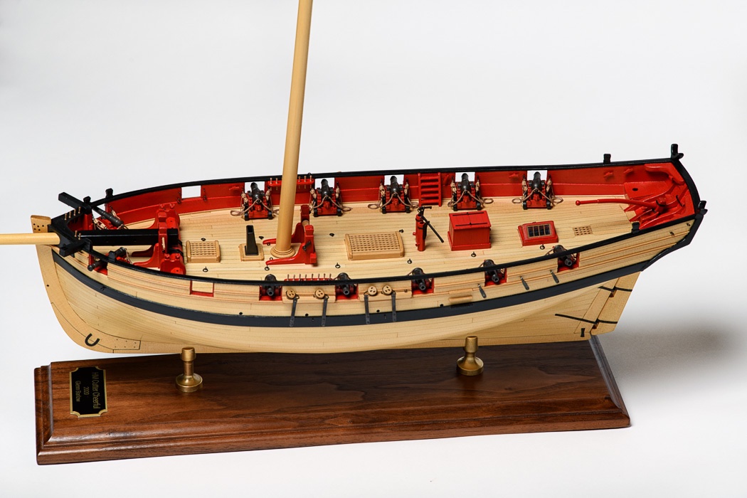
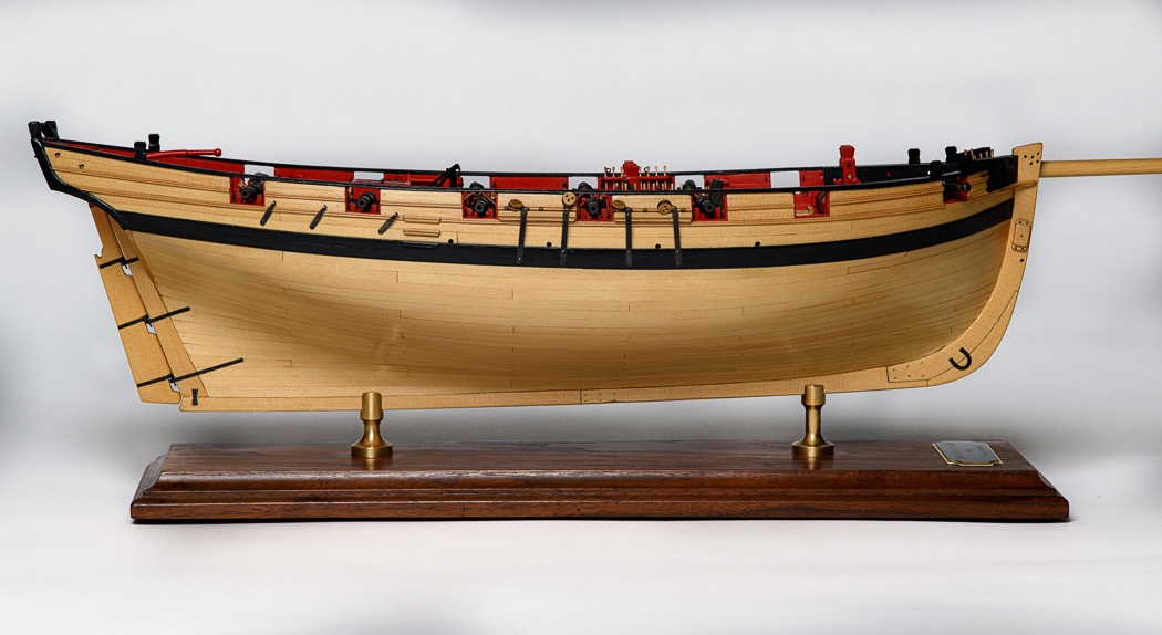
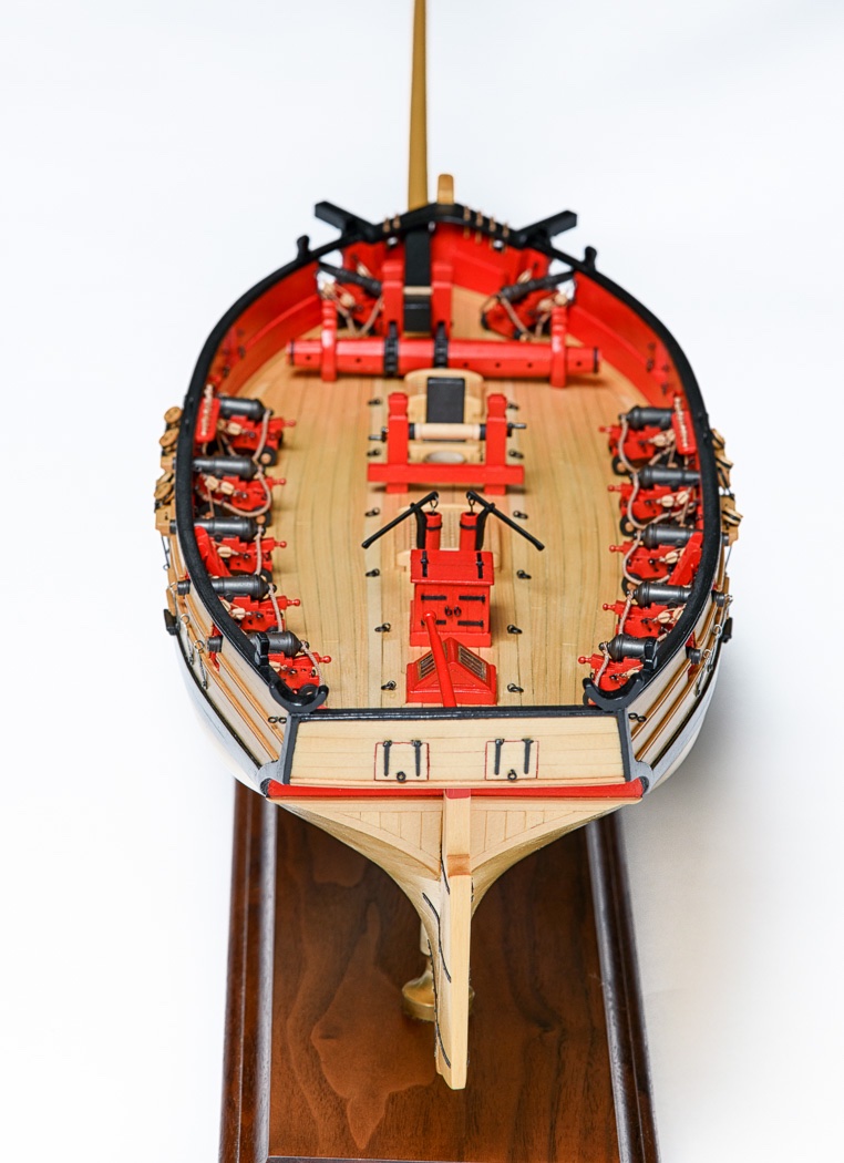
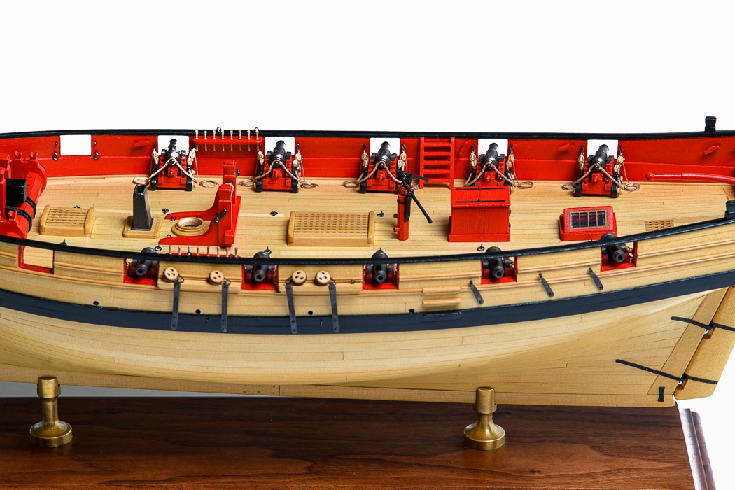
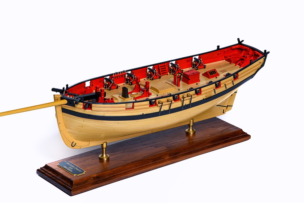
The Completed Hull It’s been a year almost to the day since I pulled out the starter kit, plans, mini-kits, and unmilled lumber to begin my build of HM Cheerful. At that point, as I read through the well written and photo supported monograph, there were so many things that I had absolutely no clue how I was going to do. It has been an adventure, I learned how to do all those things. I thought it worth a moment to pause and share a few photos of my build of Cheerful. I pulled out my camera gear to try and do her a bit of justice. The bowsprit was still installed in temporary mode and the mast is far from finished but there for contrast in one photo. So without further comment, here she is. Thanks for stopping by. I always appreciate your comments and likes.
- 778 replies
-
- 15
-
-
- cheerful
- Syren Ship Model Company
- (and 1 more)
-
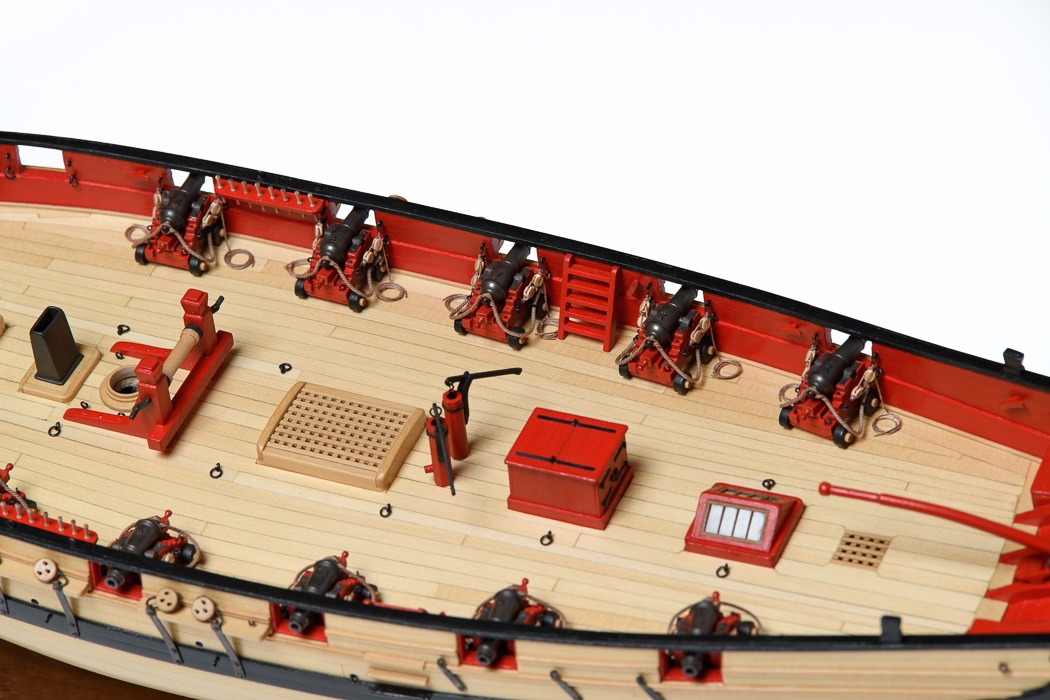
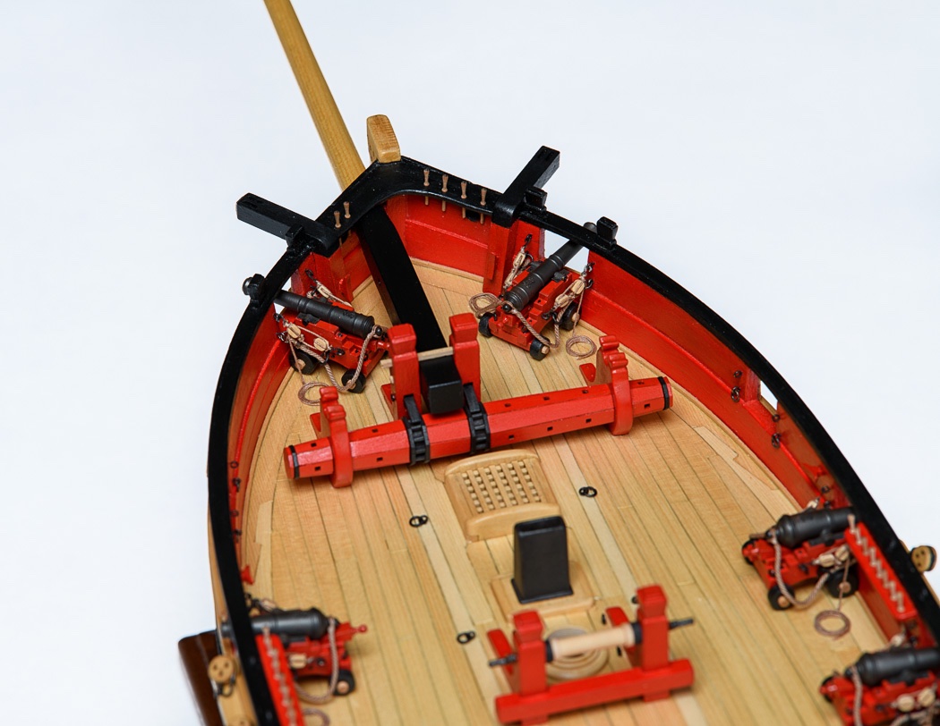
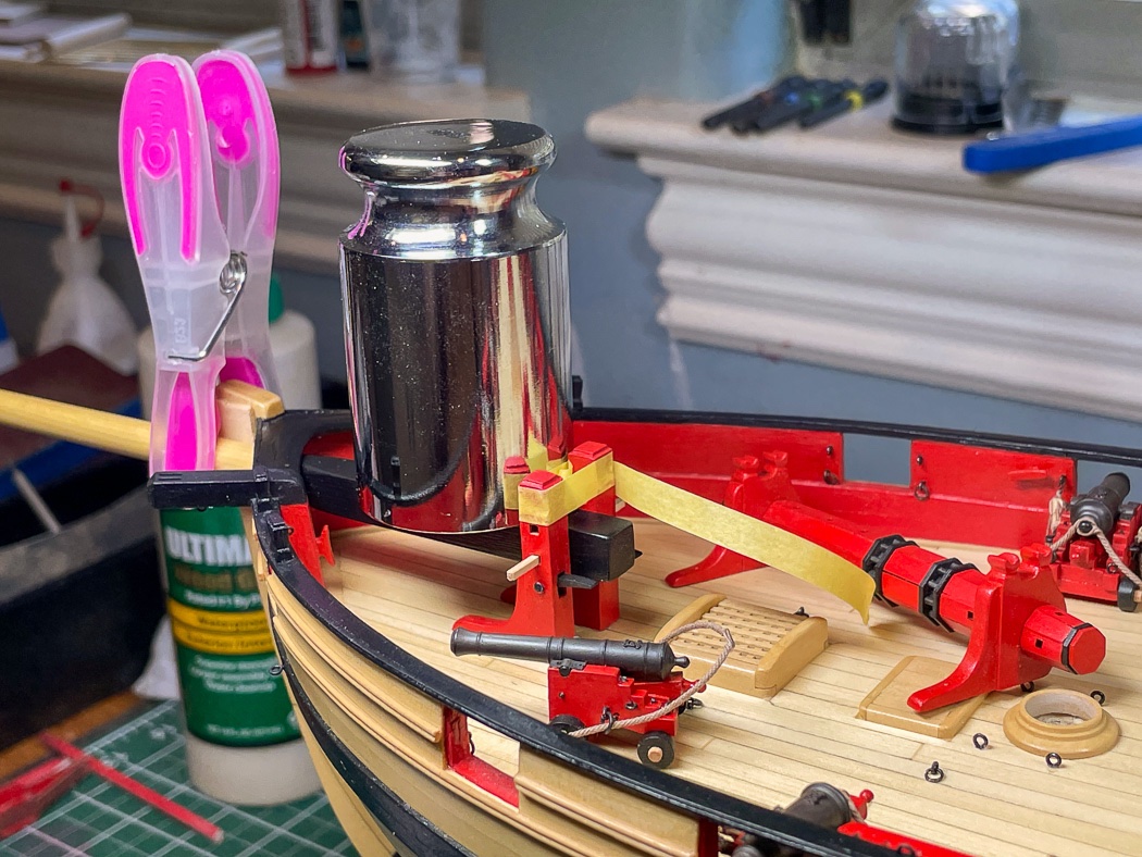
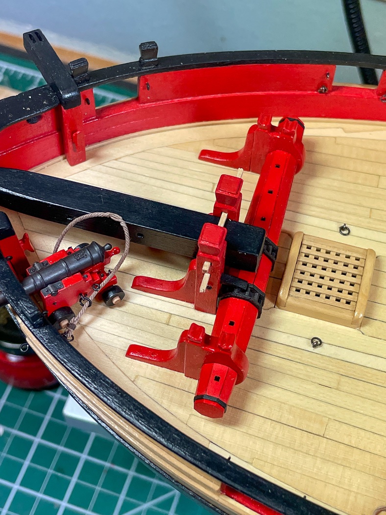
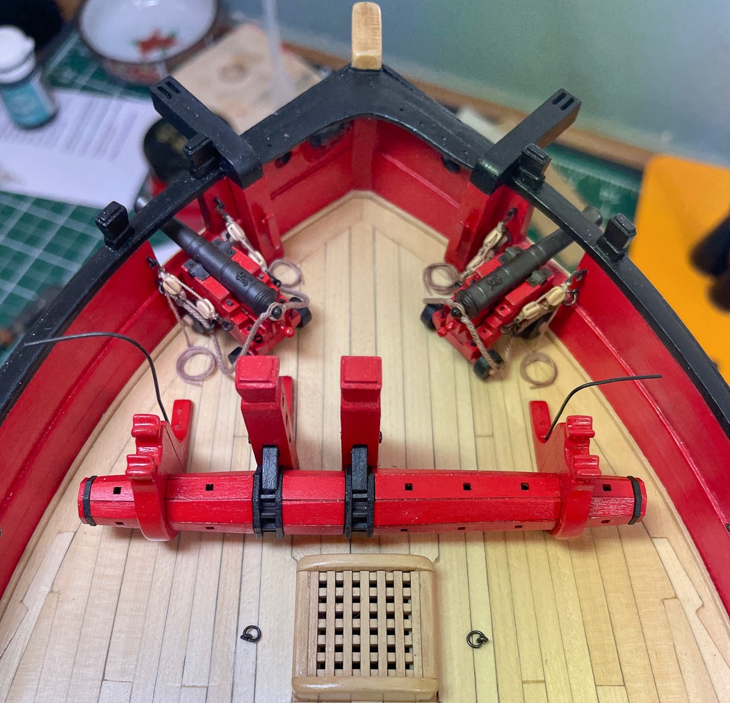
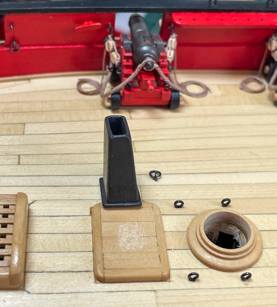
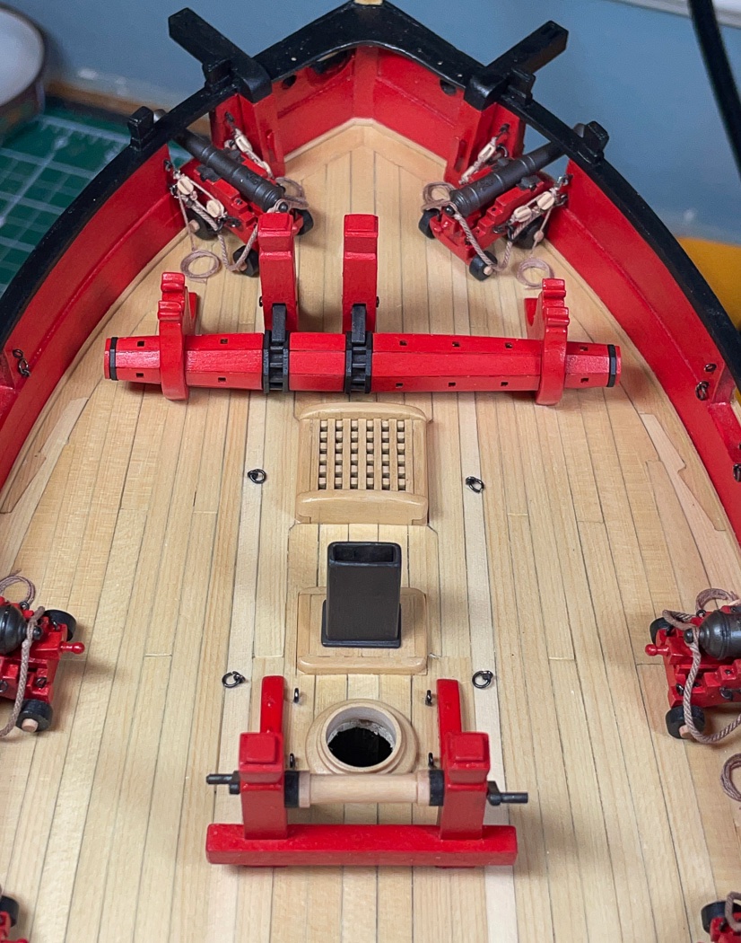
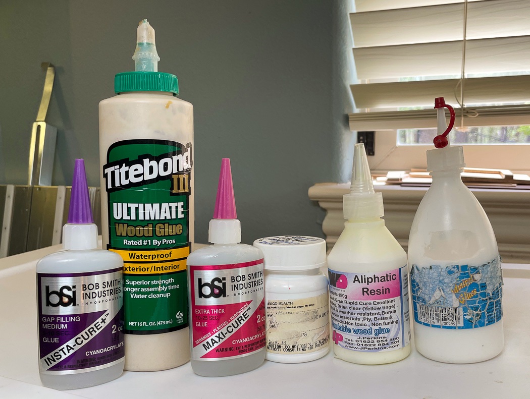
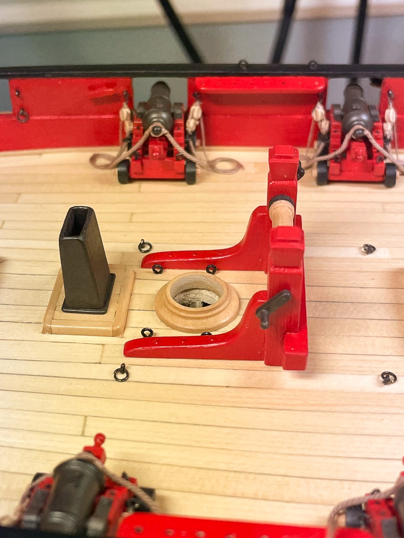
Completing the Deck I built all the remaining deck furniture some time ago, now the time has come to mount it on the deck. The first step is the tricky one of aligning the bowsprit bits, bowsprit, and windlass so they all connect in the right spots with the bowsprit in a straight-line with the hull. This is compounded by ensuring the right distance from the forward hatch and that there is room in the crowded port bow for the long gun. The placement of the bits drives everything else. Once carefully marked and checked about ten times, I glued them to the deck with the bits having a brass rod inserted in the bottom of each post and drilled through the deck. I have a spacer held by the clothes pin on the stem, the weight to press the bits tightly to the deck, and tape to keep the bits lined up tight to the bow sprit. This is another of those take a deep breath moments, it’s get it right or start a new model time. Good news, nothing fell. As I’m coming to the close of the majority of the building it dawned on me how many different glues I’ve used on this model. Each of these has served some specific purpose and have been the glue that holds the project together …see what I did there. I use Smith Industries CA glues exclusively and have for years, you can find it on Amazon if you’re interested. My bottle of Admiralty Paints White glue has served me equally well over a number of models. Of course most know Tite-Bond, I like this version because it dries clear and sets up at about the right speed for me to be able to position things properly. The small bottle is my ready supply of watered down white glue. With the bits set next up is the windlass (not really sequential, as noted all have to be lined up together). I have fake bolts on the deck furniture, this was the opportunity to actually have bolts serving a purpose. So after careful positioning the windlass I drilled thru it and the deck and locked it in temporarily with 24 gauge wire. I then removed it to give me room to mount the two chase guns in the bow. As many have noted, the location of the port gun doesn’t make a lot of sense since there is no room to work it, but it looks right sitting there from an overall cosmetic perspective, so there it sits. Once the guns were mounted I replaced the windlass, glued it down, and snipped the wire, creating two new “bolts.” I’m quite fond of Wipe On Poly, my deck has multiple coats, I’ve learned however it doesn’t bond well with other parts. Under the bits and all the deck furniture I first used my chisel and #11 blade to scratch and rough up the service of both the item I was gluing and the deck where it was going. The challenge being to not mar any visible areas. The galley chimney serves as an example but I did the same thing on all the deck furniture. Once again I used weathering powder on the chimney, though this time I used Soot instead of Rust brown. It gave the wood much more of a metal look. As I’ve said before I’ve become a big fan of O’Brien’s Weathering Powders and my pack of specialty soft brushes. Next up was the winch, again careful alignment for distance from the mast, but easier to manage than up at the bow. Brass pins beneath the posts drilled into the deck. I want to make sure anything that will have rigging is firmly fixed. Tight Bond was used for all the deck furniture along with the pins. With that the bow and midships area is complete. I also added the elm tree pumps in front of the companionway but forgot to take photos. After I took the photos I decided to replace all the line of commercial eyelets and ring bolts along the length of the deck with my own using 24 gauge wire giving a beefier look. Time to do some rigging. Thanks for stopping by.
- 778 replies
-
- 11
-
-
- cheerful
- Syren Ship Model Company
- (and 1 more)
-
servo-Derek... Your maritime knowledge is always impressive as is your attention to the smallest detail.
-
It's easier starting with square stock and rounding the round parts with the lathe following the 7-10-7 rule - lots of examples of how to go about that in various build logs. Harder to make a round dowel squared and tapered. Just a thought...
- 164 replies
-
- 1
-
-
- fly
- Victory Models
- (and 4 more)
-
Great work and creative solutions, I always learn something new from your posts. I found this simple tool for cutting brass tube using a jewelers saw. I took the handle off and clamped it with a vise. It works great. https://www.riogrande.com/product/tubing-cutter-jig-with-sliding-gauge/113841
-
I thin I described how I determine the taper in my LN log. You want to have all the planks terminating at the bow near the same width. Learning to do this comes only with practice, you’re doing great for a first model. The first step is caring about doing it right, your posts demonstrate that you do. It’s surprising to me how many don’t thinking painting solves everything.
- 26 replies
-
- 2
-
-
- First Build
- lady nelson
- (and 2 more)
-
This is better than wood filler on the second planking. Put the minimum amount of white glue in the gap, doesn’t have to be diluted very much if at all (experiment off the ship), avoid the area surrounding the gap, wipe off any glue not in the gap. hen trowel the sawdust on top of the glue in the gap in abundance. Flatten it as much as you can with a flat tool, pressing it into the gap and again avoiding the surrounding area. (Of course the dry dust will just blow off). Then don’t touch it too soon, once it’s dry lightly sand it with 320 and 400 grit. With a little practice, and it does take some practice, you almost can’t tell where it was - and not at all from a normal viewing distance. Wood filler works great on areas you’ll paint, the texture and color don’t work that well for natural areas. Have fun, glad Chuck’s plan bending technique is working for you, it was a game changer for me.
- 26 replies
-
- 2
-

-
-
- First Build
- lady nelson
- (and 2 more)
-
Thank you for saying so! Thanks for the comment Derek! As to the rope rocket, I’m sure one is in my future. However I’m glad I have the original stuff for Cheerful. Next on my list is learning how to use the Service-O-Magic...after I put it together.
-
Thank you both for the kind words. I’m glad the results show well and my posts are of some help. Also thanks for all the likes!
- 778 replies
-
- 2
-
-
- cheerful
- Syren Ship Model Company
- (and 1 more)
-
Thanks BE. Good catch and one I figured out after I did it. I appreciate your mentioning it. It was my error. I’ve since performed surgery, removing and replacing the forward hatch. That was fun. I then decided, following Chuck’s approach, not to include Hawsers at all and will instead tie off the anchors. I couldn’t bring myself to notch the main hatch. This wilI be my first model without anchor cables, so a change of pace I guess.
- 778 replies
-
- 2
-
-
- cheerful
- Syren Ship Model Company
- (and 1 more)
-
Thank you for saying so!
-
Thanks John. Must be some expensive wood in that clarinet. Good for you, I can’t play anything musical despite the required attempts of my elementary school band teacher long ago.
-
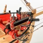
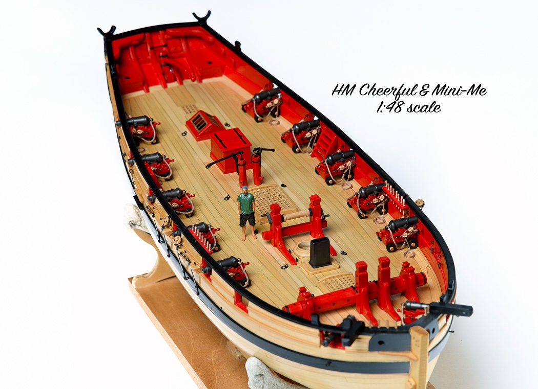
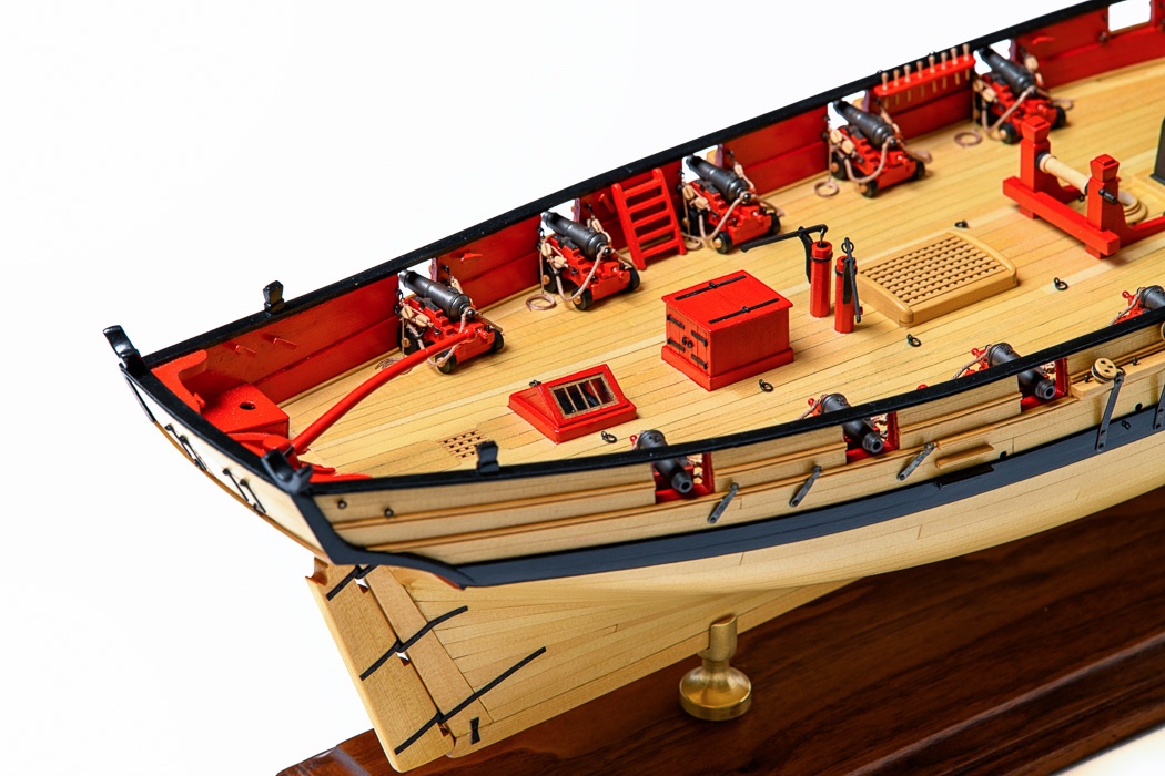
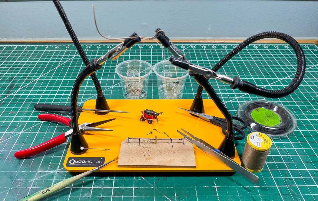
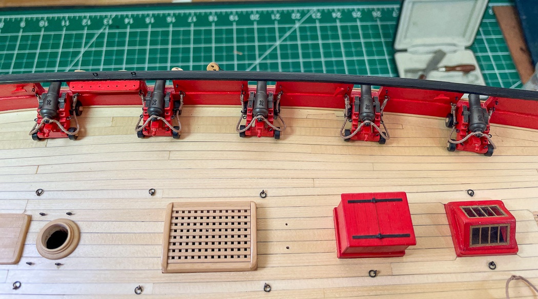
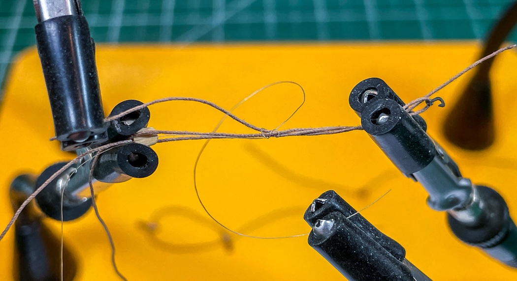
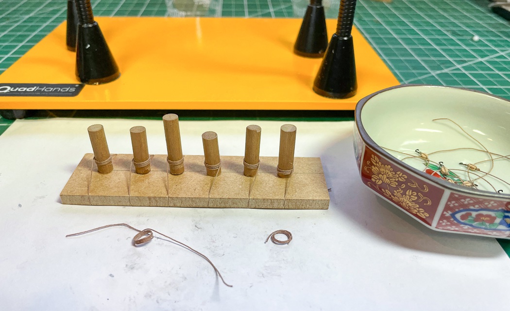
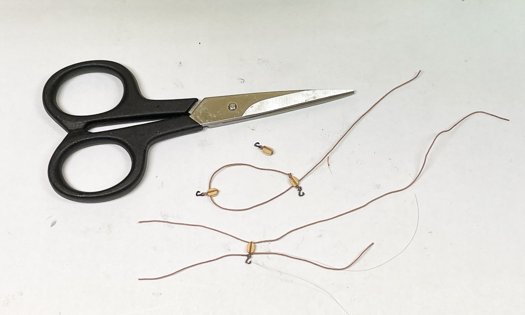
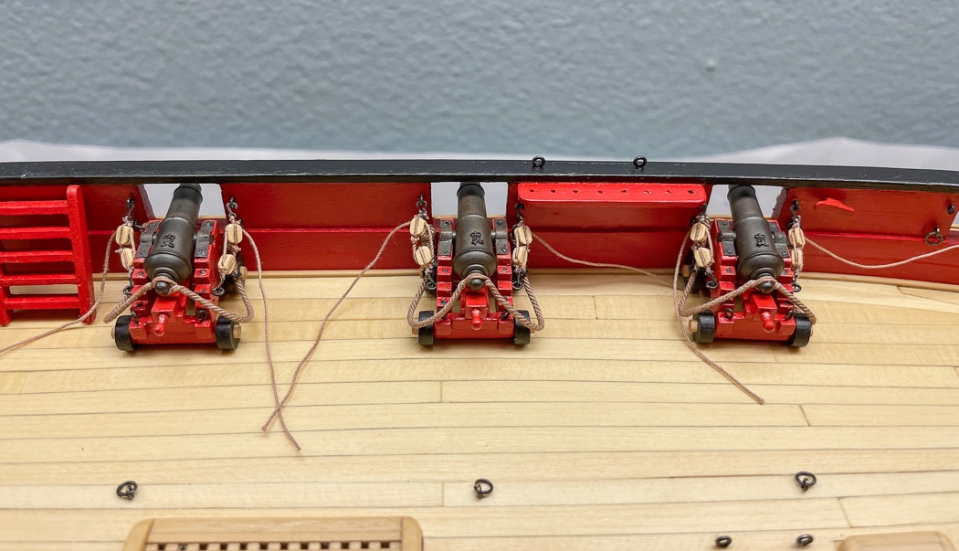
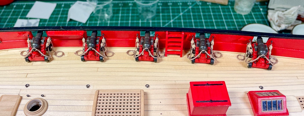
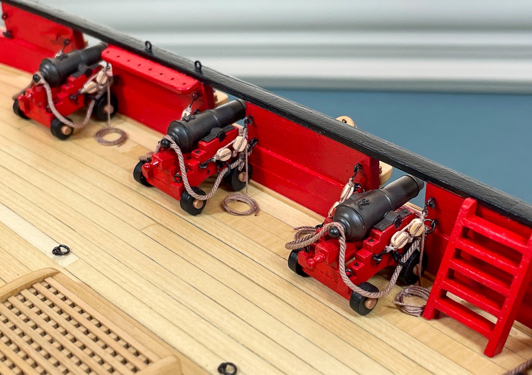
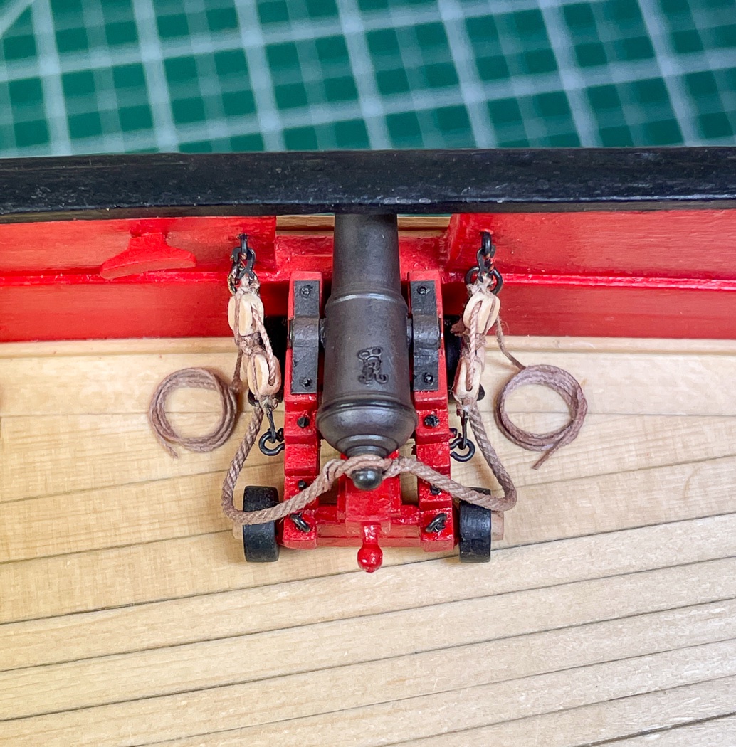
Rigging the Cannons This is something most of us have done, likely many times. True to form however, rigging Cheerful was a different approach and experience for me and once again I learned new things. Mostly following the monograph, here’s how I did mine. First up was making the breeching ropes. I used now historical .035 light brown rope from Syren, fortunately I bought all the required rope for Cheerful long ago. I created a simple jig that aided me in sizing each rope to 3 inches in length fitted with an eyebolt and ring on either end, an eyebolt and ring within those for attaching to the gun carriage and a brass rod to form the splice for the button. The photo shows the various tools and materials I used. As I've said before I’m really enjoying the quad hands. It's a great upgrade from the old version I’d used for years, it just makes things easier. In this instance I wanted the breech line seizing to show, so I used common thread. I was ok with 3mm commercial split rings and eyelets on the line ends, as they are essentially equal to the recommended 28 gauge. However I made my own larger split rings for the carriages from 24 gauge wire for a heavier look. Following the monograph, I used a sharp pointy thing to pierce the rope, dividing it into two lines either side, placed that over the brass rod then used watered down white glue to semi-harden it into shape. Once I’d settled on a process and finished one, I then did 13 more. With those made I attached one to each gun carriage off the ship. Really no need for a jig to do this, it’s just a matter of gluing in the eyelets either side. I did not attach the splice, I wanted to pull the rope back out of the way when I mounted the guns on the ship. I mounted the guns using Smith Industries Maxi-Cure Extra thick CA glue, I use Smith Industries Medium CA for everything else but in the case of the guns I want the extra strong bond the Maxi-Cure provides. I applied a small dab on each wheel, held the carriage above the deck (don’t drop it Glenn, don’t drop it…) as I guided it through the port, then outboard by the barrel as I lined it up to the port opening. It’s a dicey moment or two as I set the carriage carefully down onto the deck, first the front wheels then the back. I breath for the first time in 30 seconds then move to the next one. Once the maxi-cure sets I’m comfortable the guns aren’t going anywhere. Once mounted I attached the breeching rope to the bulwarks, placed the splice onto the button, and did a little shaping of the hang of the line. The size of the splice is set so it’s a tight fit, precluding the need for any glue that would mar the barrel, again guidance from Chuck’s monograph. Back to the quad hands to make up the gun tackle using Syren .012 light brown rope, small 3mm PE hooks, and Syren 1/8th single blocks. I may not have needed to use all four hands, but it did make it easier by doing so (I loosened everything up for the photo to make it easier to see). The hands hold the block on one end and the hook on the other with the running line through the seizing line at the head of the block. The rope is looped then seized, in this case using tan fishing lure line, or as I like to call it some blond lady’s hair, though hair may be thicker. Through experimentation I learned there is very little space between bulwark and gun carriage eyelets, the tackle needs to be tightly done to fit, and it this instance I didn’t want the seizing to dominate. I know there are many ways, means and methods to seizing blocks, the figure eight loop and seizing is the way I prefer. I would like to sort out how @Chuck does it so precise and neatly but until then this is the best I can do, it works for me. I’ve literally done hundreds of these over the years and can pretty quickly knock them out. It comes off the quad hands as shown on the bottom of the photo. I tie the running line using half hitches, a knot I can slide tight to the block and firm to itself. I had tried seizing here as well, but it took up too much of the limited space on board so I switched to the half hitches. Once I did one I did 27 more, ok really like 34 more, I didn’t like how some came out. Then it’s time to make up rope coils. I have done the flemish coils (or whatever they’re called) on a prior model and I may do frapping on a future one. In this case I wanted natural looking coils that vary in appearance as though done by different gun crews and left laying out of the way, semi-neatly but not Admiral’s inspection ready. So that’s what I did using .012 line wrapped four times around a dowel, wet with very watered down white glue so as not to cake. Taken off the dowel after drying and trimmed I then basically mashed each with my finger. I made more than the 28 required to get what I wanted - the mashed finger approach is not a precision method. I also wrapped half to the left and half to the right to have them coiled appropriately either side of the gun. The hooks of each tackle were connected to both bulwarks and carriage and gently tightened. As you can see there isn’t much space to work with. To be clear though, this is not a scale problem, I checked it with mini-me:-). The blocks are the appropriate size, the carriages of the carronade are just shorter and smaller than a cannon of that scale and of course the guns are completely drawn in tight to the bulwarks. I’m going to miss Syren rope, it is so authentic appearing. I suppose some day I’ll have to learn to make it with a rope-walk like many do and many more will do with it no longer being a Syren offering. The running line is snipped and glued to the deck with CA. The coils were added, glued on top with Aliphatic Resin for its colorless appearance and longer setting time. This allowed me to position the coils such that they appear to be a continuation of the tackle (I know, gun rigging 101). And with that the carronades are mounted and rigged, the cannon at the bow will wait until the next step of installing the bowsprit and winch. The tackle is already made up, I just need to take stock of the limited space. Next up is mounting the deck furniture I made up long ago and that will be it for finishing the hull. Thanks for stopping by, the follows, comments, and likes are very appreciated.
- 778 replies
-
- 16
-
-
- cheerful
- Syren Ship Model Company
- (and 1 more)
-
Well said James. As you noted there is a separate forum topic for MDF discussion (which I will never visit). It doesn't need to come up every time you post a build log. This and many models are built with MDF, let's focus on how it's built not what it's built with.
- 355 replies
-
- 8
-
-
-
- vanguard models
- Sphinx
- (and 1 more)
-
Always fun to watch your build of a Chris design. Excellent!
- 355 replies
-
- 5
-
-
- vanguard models
- Sphinx
- (and 1 more)