Elia
-
Posts
551 -
Joined
-
Last visited
Content Type
Profiles
Forums
Gallery
Events
Everything posted by Elia
-
 Bob, That deck and furniture look great - very clean and tidy and to scale. Excellent work. Cheers, Elia
 -
Beautiful work on that hull, deck, bulwarks and stanchions. Oh so nice! Elia
-
Russ, I like the cabin, the entryway, and those windows. Very nice and well scaled to the hull. Those dead eyes look good and oh boy they are tiny. My Arethusa dead eyes were 0.15 inches in diameter and I thought I had difficulties. Your's are so so small at 0.06 in diameter. Very nice work. Elia
-
Druxey, I've had the same question. I purchased Britannia metal blocks for my schooner from Blue Jacket Shipcrafters. The blocks are internally iron stropped with wooden shells. I would like them to look like varnished wood. I'll experiment with your suggestions. I bought bass wood strips for the masting and spars and would like the blocks, masts , and spars to appear reasonably similar. I've got a number of different Minwax stains I could use on the wood components. Do you have any thoughts on an approach? Thank you, Elia
-
Amazing result Danny. It's hard to draw a link between those first two photos of your last post. Outstanding effort sir. Cheers, Elia
-
Omega, Very impressive work on such a tiny and delicate hull. The hull lines look sweet, and I look forward to seeing this little beauty continue. Cheers, Elia
-
John, You've got another little gem going there! The keel and framing looks quite smart. As Russ noted - those cant frames look sharp. Cheers, Elia
-
Bob, Very nice work on that windlass and all it's components. Sweet. Cheers, Elia
-
Danny, This is an amazing and a miraculous salvage effort. Very well done. Cheers, Elia
-
Michael, That ought to be the sub-title of my modeling hobby. Thank you much. Cheers, Elia
-
Darrel, I've following along here and just wanted to say that I think you're doing a fine on your Bluenose model. I enjoy each update. Excellent first effort. Cheers, Elia
-
Bob, Thank you. The fish pens shown athwartship of the forward fish hatch were used to dump catch off of the dories. Interestingly I've seen pictures of dories, nested, and placed keel up, on those rails. The guides along the main rails, the sides of the main hatch, the bait gurry, and cabin are called checker or dividing board guides. Boards were placed in the slots of the guides to provide bins for fishing being processes (split, gutted, etc). I've seen only a few models with these, which is kind of funny, since many fishing schooners other than the mackerel seiners employed them. Here are links to a few images I've found on the web showing them. http://penobscotmarinemuseum.org/pbho-1/tags/fisheries (The very bottom picture of the images on the left side) http://ghwalk.org/story-moments/21 In Chapelle's The American Fishing Schooners, 1825 - 1935, page 406 on the lower half of the page, you see a couple of sketches showing a general arrangement of the guides. Also on page 386 in bulwarks subsection, at the top of the page one finds some main/monkey rail checker board guide sketches. If you can find Thomas Hoyne's artwork of the Banks fishermen you find many paintings showing the checker boards. Erik A.R. Ronnberg made an impressive series of 3/8 scale models of the lineage of Gloucester fishing schooners for Hoyne which he then used to develop his artwork. As a last note images from Mystic Museum were posted here at MSW2 of ship models and one of them is one of Ronnberg's 3/8 scale ...Cavalier...and you can readily see the checker boards on it, too. http://modelshipworld.com/index.php?/topic/3662-mystic-seaport-models/?p=103570 I hope this all helps. Cheers, Elia
-
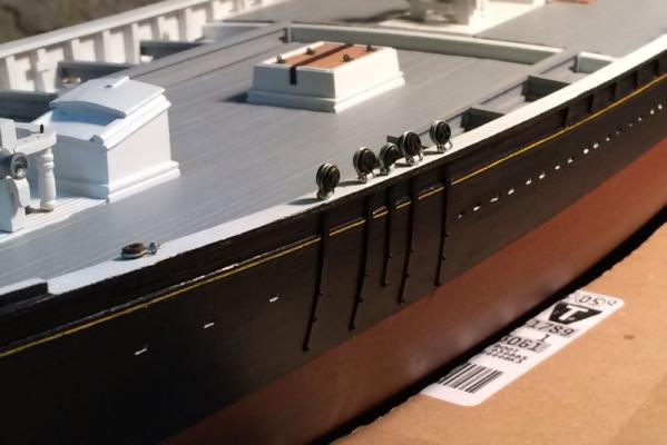
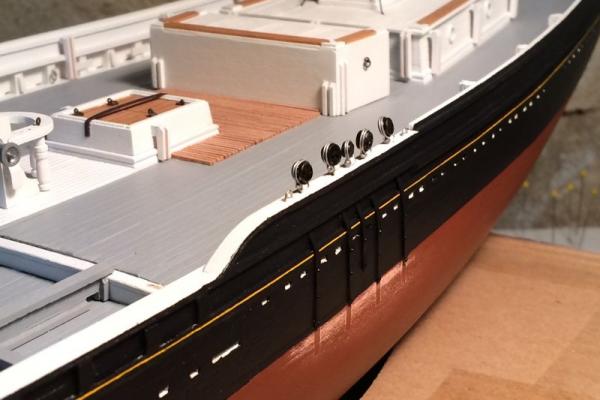
Earlier than my steering wheel endeavor I had fabricated the cat heads and installed the chainplates. All of the deck furniture remains only temporarily placed for context. Funny thing about the deadeyes - they don't want to stand upright, as in the photos. They lay over, free on their pivot pins... And last, but not least, thank you to all those who've 'liked' my updates! Cheers, Elia
- 200 replies
-
- 25
-

-
Alfons, Thank you, and thanks for stopping by! Bob, So true. I had sketched out all of the steps in that process. And like many perfect plans...once underway changes and adjustments were made. Cheers, Elia
-
Michael, Omega, Bob, Many thanks. I had fun making the little ship's wheel rim (with a little excitement thrown in for good measure). Bob - I derive satisfaction in finding fabrication solutions to modeling [and even full scale:) ] and being able to pull them off. Those first attempts were quite frustrating and probably set me back at least 6 weeks (try, fail, ponder, adjust, try agin, fail, ponder,.....). I've schemed up an approach to the hub so maybe soon I'll have something to show on it. I'll post some pictures of the cat heads and installed chainplates soon. Cheers, Elia
-
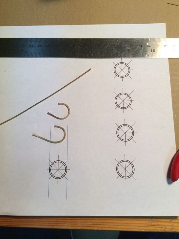
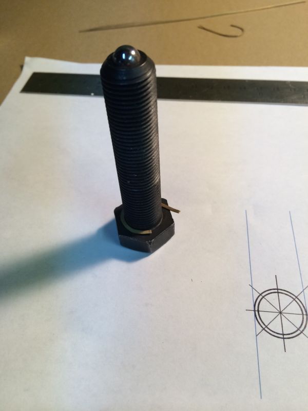
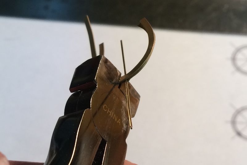
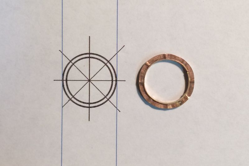
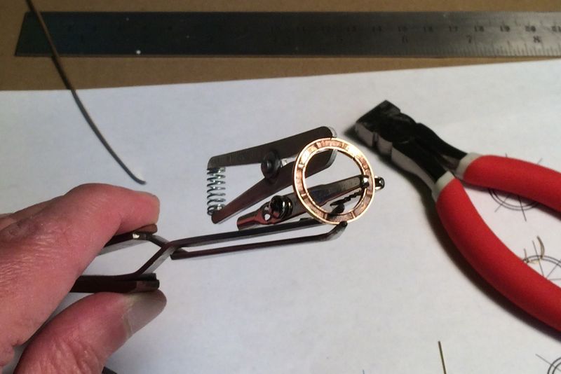
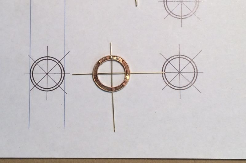
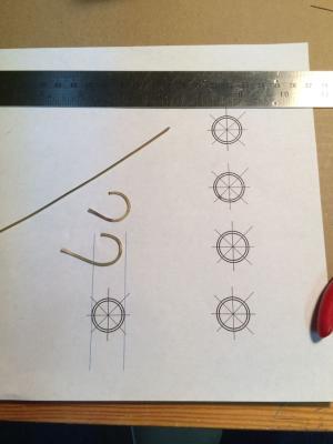
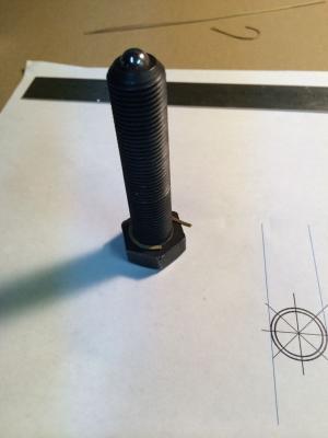
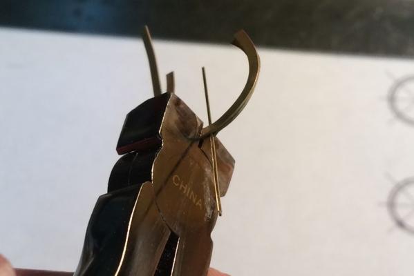
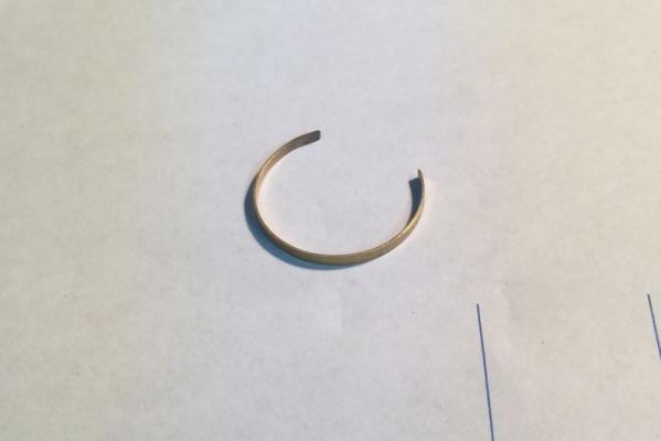
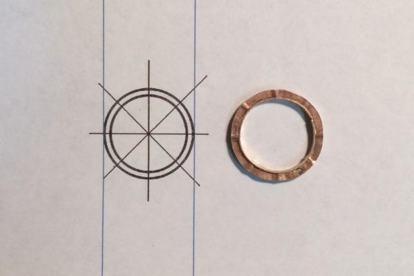
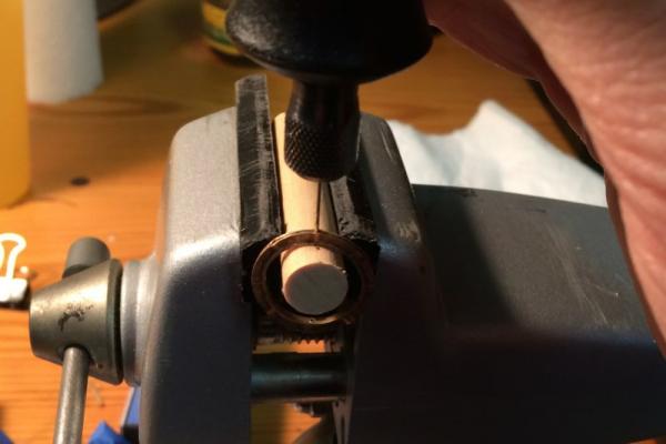
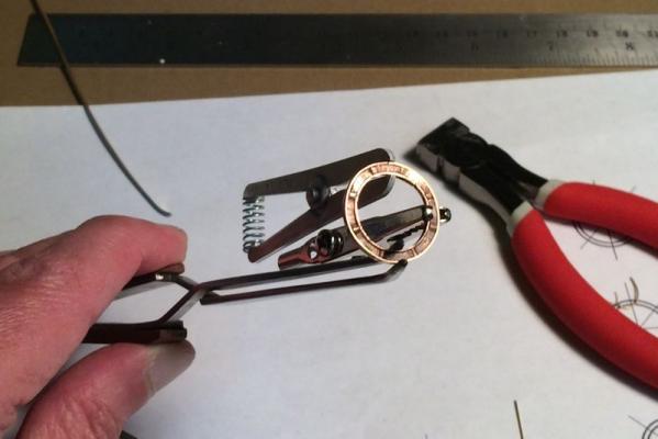
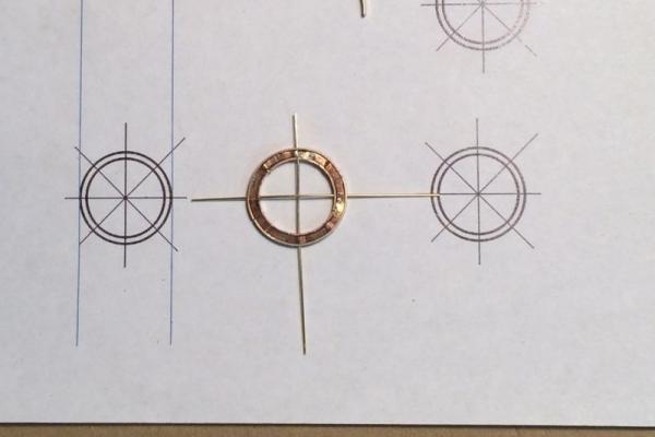
This past winter and spring I pondered how to fabricate a few of the remaining deck furniture details for Arethusa. The steering wheel, the cat heads, and potentially remaking the deck pumps, due to the fact that over time, as I stared at my original sculpey ones, I found them a little less than attractive. We’ll see if I remake the pumps or not. The Gloucester schooners of the late 1800s and early 1900s employed cast steering wheels over the built-up wooden wheels we see on many earlier period ships. One of the principal manufacturers of the cast wheels was A.P. Stoddard Company of Gloucester, MA. The wheels contained a cast rim, a cast hub, and 8 spoke/handles. The overall dimensions of the wheels ranged from about 30 inches in diameter (of the rim) to 36 inches diameter. The design I am using was for Elsie, a similar vintage and approximately similar sized schooner to Arethusa. The Elsie plans from Model Shipways contain views of the wheel, but enlarged to 1/24 scale, twice the size of my model. This wheel was also printed in a series of articles Erik A.R. Ronnberg wrote from the Nautical Research Guild's Journal in the 1990s. (I think). So I used CAD at work to create a 1/48 scale set of ‘wheel’ drawings. Since the wheel details are quite small at 1/48 scale, I only focused on the major geometric details. The Elsie wheel is 48 inches (true) from brass cap of one handle to the opposite side handle brass cap. The rim is 36 inches OD, and 30 inches ID. In this post I’ll show you my approach to making the ships wheel. What follows is my fourth or fifth attempt at the wheel. I first tried making one from sheet styrene. No luck. Then I tried using boxwood and styrene. Again failure. I followed that up with an all boxwood wheel’s rim. Nope, no good. At the top of my wish list of of modeling power tools is a lathe… but with largish scale home projects ongoing I can’t justify such a purchase right now. What I found I was struggling with was the fact that the flanges and the web of the rim as very thin at 1/48 scale. Couple that with a detail the cast rims present - ‘cylindrical’ swells around each spoke at the rim - and, well, I was stumped. Then, one night something struck me - why not make the rim’s web from two thin sheets of brass. Once I had the ‘rings’ of the web formed it seemed it shouldn’t be too difficult to crimp them around spokes, or at least spoke mandrels. In my ‘brass’ box I had a nice amount of 1/64” thick by 1/16” wide K&S brass strips. I also had brass sheets stock but attempts to cut out the rings to an acceptable shape proved difficult for me. I annealed the 1/64 x 1/16 strips and found a suitable mandrel with which to form the web rings. The mandrel was part of a VW Passat B5 tie rod extraction tool (from a past project/era). I first crudely formed the strips into flat rings, re-annealing throughout the forming, to allow the rings to take a smooth shape. I then used the mandrel to allow final forming along the underside of the bolt head (following picture). The ring’s ends were then soldered together to form what are essentially thin brass washers. For this step I used silver solder paste and my butane torch. The next picture shows the crimping of the two ring webs around 0.020 brass rod, which at scale is slightly larger than correct, but available and easy to work with. These are demonstration rings, as my originals had passed this point of the process before I paused long enough to consider taking pictures. I used the CAD print to mark where the spokes would be placed. Once all of the crimping around the spoke locations was complete I soldered the two web sides together. For this solder step I used Stay Brite silver solder, which has a melting temp in the somewhere around ~500F. I soldered in every-other ‘bay’ between spoke locations. I did that so that when I soldered the flanges onto the rim I could alternate bay locations, providing some ‘distance’ between soldered joints in an attempt to minimize secondary or tertiary soldering from undoing prior soldered sections. I used my trusty mandrel to form the inner flange of the rim, fitted it to the inside of the web ring, trimmed it, and soldered it on place, using the designated ‘clear’ bays for soldering. I then used a wooden dowel as a back stop and drilled though the inner flange with my dremel. Nearing the completion of the rim I used another mandrel to form the outer flange. I clamped it in place, marked the spoke locations, and drilled the holes using the prior mentioned drill setup. Parts were filed, flux was applied. I used some of those 0.020 inch brass rods to maintain alignment of the holes to the rim web. I used clamps to keep everything in place. I snipped tiny pieces of TIX solder (melt temp around 270F), and located them. Heat was then applied. It looked great. Really sweet. I took off the clamps and went to remove the brass rods. Oh CRUD! [actually, insert colorful sailor language here]. The flux and solder had run…and the brass rods were soldered in. I tried heat with the soldering iron, but no luck. I was concerned about applying too much heat and having other portions of the assembly come apart. So I set about marking and drilling out the brass rod material. It worked OK, although the holes weren’t quite as well located as the originals. On the second portion of the outer flange I chose to omit the brass rod ‘alignment’ aids and it all worked out well. So here is the rim essentially completed. The swells in the rim web are visible, and the rim flanges are reasonably to scale. It is a little larger in OD than the plans. Not perfect, but I’m happy with it. Now on to the tiny hub. Cheers, Elia
- 200 replies
-
- 10
-
-
Michael, JesseLee, Russ, Thanks! I'm working towards an update soon. Russ I look forward to seeing more of your art, and oh boy - Arethusa! Cheers, Elia
-
Bob, I'm glad it helped you with yours. Those were a good learning experience for me. Cheers, Elia
-
Bob, Your Lettie decking and rails look great. I really like the inner transom planking, the deck planking, the sweep of the main and monkey rails around the transom, the buffalo chocks, and the grub beam. Did you scrape or sand the deck planking? It looks very smooth. Nicely done! I look forward to seeing the deck furniture take shape. Elia PS this build log is one of my few 'first stops' when catching up at MSW - I always enjoy seeing your progress.
-
Dimitris, Nils, Russ, Thank you all for the sentiments and compliments. A good day it has been. I hope to have an update soon. I'm on my third (or fourth?) attempt at making the ships wheel....and I 'think' this time is it. . Time will tell. Russ, your are so fortunate to live in Mystic. I'm outside of Philadelphia and rarely travel up there. I've wanted to see Erik's models and Thom Hoyne's artwork but haven't had the opportunity yet. Your paintings are superb. Wow. I would love to see your take on Arethusa. Cheers, Elia
-
Dimitris, Thank you. Though my work has slowed it has been an enjoyable and rewarding journey. Elia
-
Bob, Very nicely formed strops and chainplate assemblies. Those are some details and smartly complement your schooner. Cheers, Elia
-
Peter, I too am very glad to see you back. I'll enjoy seeing your log rebuilt (and reference it many timed, as was done in the past), but really look forward to seeing further progress on this beautiful model. Cheers, Elia
-
Bob, Super job on the hawse hole and hawse pipe. That flared outer flange /lip looks outstanding. Very nice inner plate, too. Cheers, Elia
-
Nice job on the dead eyes, strops, and chain plates PopJack. They look sharp on the hull. I think they'll look quite fine installed on the hull, and setting them into the hull planking by, what 0.015"?, would be quite a challenge. Well done. Elia