druxey
-
Posts
13,395 -
Joined
-
Last visited
Content Type
Profiles
Forums
Gallery
Events
Everything posted by druxey
-
 As Oscar Wilde said, "You will, you will," Michael!
- 641 replies
-
- 6
-

-
- greenwich hospital
- barge
- (and 1 more)
-
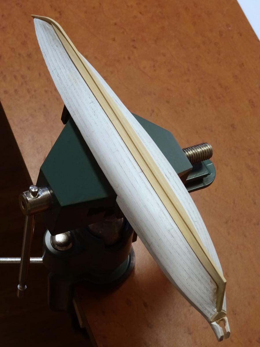
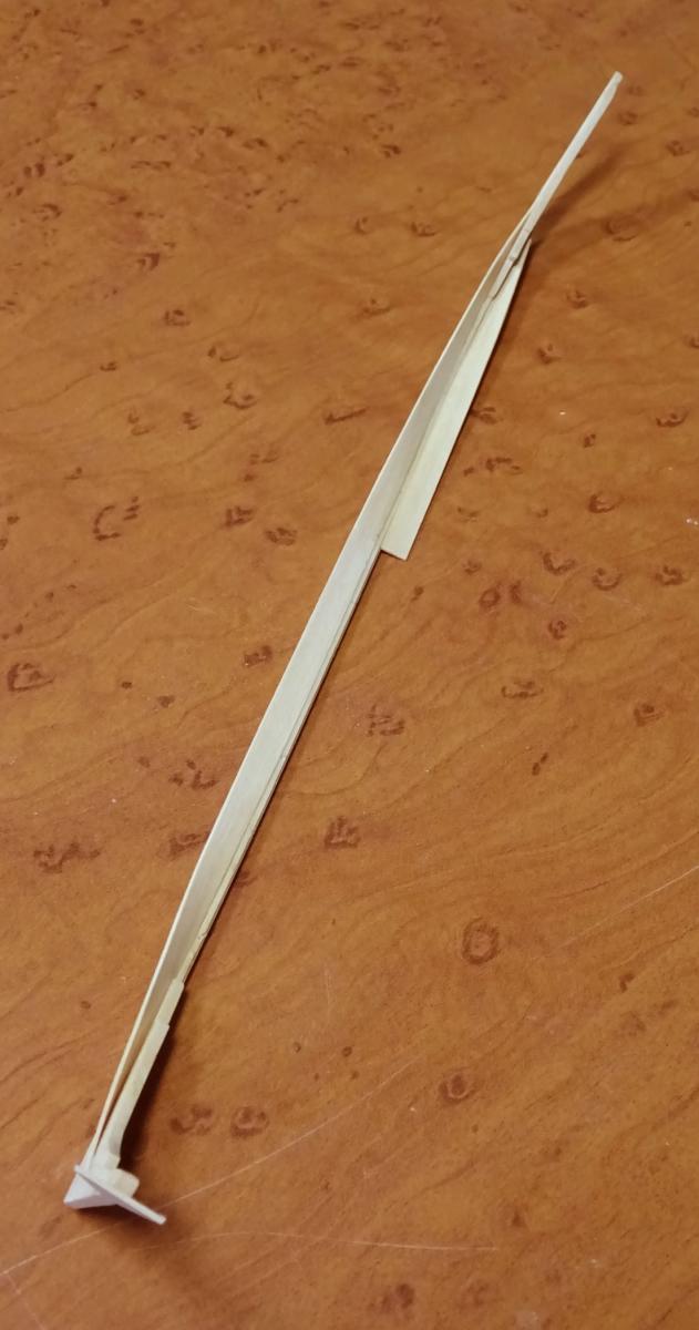
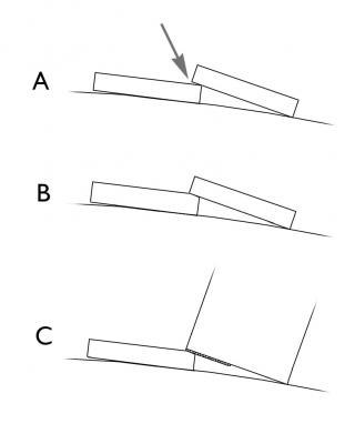
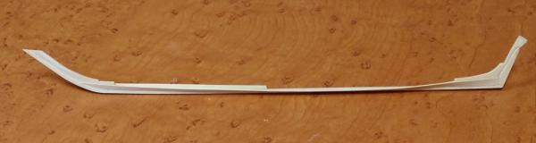
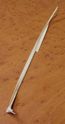
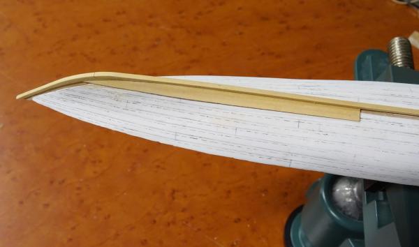
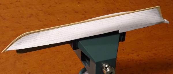
A little more time was spent on completing the starboard garboard strake. The next step is to shape the lands for the second strake of planking. If one were to omit this step, the second strake would not have any gluing surface and there would be a gap under the strake, A. Obviously, a bevel is required. It varies in angle along the strake according to hull curvature, B. To cut this accurately, I took some scrap wood the width of a strake and rubber cemented some 220 grit sandpaper along one edge, C. Keeping the 'safe' corner of this along the mark-out of the second strake's far edge, it is easy to shape the correct bevel along the installed strake. The next instalment will show this completed. A note: I found the short pins under the keel not very effective in holding the keel straight, as the keel kept popping off. On a another long narrow hull I would drill the pins all the way through the keel. A digression: One side effect of modelling an open boat at this small scale is the amount of wood required to build it. Very little is needed, making this a very economic exercise in materials, but not in time.

- 641 replies
-
- 44
-
-
- greenwich hospital
- barge
- (and 1 more)
-
Michael: I cut the stock several thou over-thick on a Byrnes saw with a micrometer adjustable fence. I then process it through his thickness sander to within .004" of finished dimension. A fine sanding block removes sanding marks and completes the prepared stock. The leaves I'm using are just under ¾" wide. George: gesso is the (usually) white compound artists use to prime canvases. These days it has an acrylic base. Once dry, one can sand it to a very smooth surface. Any reputable art store will carry gesso. (The word is pronounced with a hard 'g', as in 'jesso' - or 'George'!) Thanks again for the 'likes', folks.
- 641 replies
-
- 10
-
-
- greenwich hospital
- barge
- (and 1 more)
-
THE 74-GUN SHIP by Jeronimo
druxey replied to Jeronimo's topic in - Build logs for subjects built 1751 - 1800
Exemplary work, Karl! -
Surprisingly little pigment powder is required to color glue. I prefer to mix a small amount of pigment into paste with water before mixing with white glue. As Ed says, the mix will dry much darker than the liquid glue. Please wear respiratory protection as the pigment powder is very fine and easily becomes airborne.
-
Frankie: lead deteriorates at a rate dependent on the atmosphere and temperature it's exposed to. I've seen lead 'fuzz' in comparatively recent models and still undeteriorated lead in older models. Either way, it's toxic stuff and needs to be handled and disposed of appropriately. I've currently got a model for conservation with about 70-year old corroded lead cell batteries in it. They (and the lead-based paint that's flaking off) go to the hazardous waste disposal site.
-
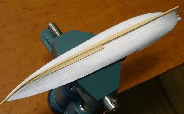
Further progress. The garboard is in on the port side and the forward plank on the starboard. The interesting thing is that, at any point in planking, provided one has spiled and shaped the plank to lie without stress, one can remove the model from the plug and it will retain its shape.
- 641 replies
-
- 43
-
-
- greenwich hospital
- barge
- (and 1 more)
-
Joel: stay with this log and all will be revealed! In short, the laps will be bevelled in a while and gains cut at bow and stern. It will be done just as in full-size practice, but considerably smaller.
- 641 replies
-
- 5
-
-
- greenwich hospital
- barge
- (and 1 more)
-
Sweet! She's looking good.
-
If that was your first attempt at carved lettering - well done, Michael! And that you used a simple #11 blade rather than miniature carving tools is even more remarkable.
-
Thank you, gentlemen all. Finally had some quality time on the model. The first garboard plank is now spiled, cut, shaped and fitted. The stock is thin enough to cut with a sharp scalpel blade. The twist was achieved by cold wet bending and holding in place using rubber bands until dry. Castello takes more persuasion to bend than holly. Once the plank was dry, it was glued in place. I needed to cut back the plug more at the bow to allow the plank to land nicely in the bow rabbet. One plank down, many more to go!
- 641 replies
-
- 36
-
-
- greenwich hospital
- barge
- (and 1 more)
-
A two year old? What were they thinking???? Anyway, both models are a good restoration challenge and I'm looking forward to seeing them returned to their former glory. Good luck with them.
-
That is exactly so.
-
White Paint Issues
druxey replied to rynmss's topic in Painting, finishing and weathering products and techniques
And is the paint well stirred? In some paints the pigment tends to settle out fairly quickly. -
Thanks for all the 'likes' and comments, everyone. Dan: the planking butts are arranged to fall on the frames in the model. I'm not going as far as bevelled and clenched joints on 1/64" thick material! This is a 1:48 scale exercise. I may be mad, but not entirely crazy.
- 641 replies
-
- 8
-
-
- greenwich hospital
- barge
- (and 1 more)
-
Very nicely done! Catheads would have been of a single piece of compass timber for strength. They were probably cut from the bottom of the tree trunk where the roots spread out at the correct angle. (The cathead's shape would be upside-down when the tree was upright.)
-
That's correct, Joel - I hope! The last clinker boat I built was done this way. It's amazing how clinker planking holds the boat's shape. I even took the boat off the plug when half-planked to demonstrate. The frames will be bent in later on in the process.
- 641 replies
-
- 6
-
-
- greenwich hospital
- barge
- (and 1 more)
-
After the full model, you should be able to do the deck framing in your sleep, Dan! Looking good.
-
Yes, I agree - what you've done is akin to watchmaking! Well played, Ed.
- 3,618 replies
-
- 7
-
-
- young america
- clipper
- (and 1 more)
-
Looking good, but has the fore end of the coaming come adrift?
- 258 replies
-
- 4
-
-
- buzzards bay
- herreshoff
- (and 1 more)
-
A small update: Before waxing the plug, I drew in the overlaps of the clinker planking. I made them 1" wide and are seen as dashed lines on the plug. Two coats of Clapham's beeswax polish were used over the mark-out. Leaves of ¾" thick Castello have now been prepared for the planking. They were cut a little over-thick and then taken down almost to spec on a thickness sander. Finer grades of sandpaper on sanding blocks produced a smooth surface. Hopefully there will be time to commence planking soon.
- 641 replies
-
- 33
-
-
- greenwich hospital
- barge
- (and 1 more)
-
ancre Le Fleuron 1729 by rekon54 - 1:24
druxey replied to rekon54's topic in - Build logs for subjects built 1501 - 1750
Lovely details! -
Quite the forest of ventilators!
- 2,625 replies
-
- 4
-
-
- kaiser wilhelm der grosse
- passenger steamer
- (and 1 more)
-
Delightful detail, Michael.
-
Echo by Maury S - FINISHED - Cross-Section
druxey replied to Maury S's topic in - Build logs for subjects built 1751 - 1800
That's a different kind of display case and works wonderfully. Well done, Maury.