druxey
-
Posts
13,402 -
Joined
-
Last visited
Content Type
Profiles
Forums
Gallery
Events
Everything posted by druxey
-
 Endless: some contemporary models and plans do show the discharge tube exiting the counter. Looking great, Chuck!
- 1,051 replies
-
- 4
-

-
- cheerful
- Syren Ship Model Company
- (and 1 more)
-
ancre le rochefort by cabrapente
druxey replied to cabrapente's topic in - Build logs for subjects built 1751 - 1800
That's a flying start! You've a lot of pieces cut already. -
Looking lovely, Mike. Are you planning to pin the windlass to the deck as well?
- 452 replies
-
- 3
-
-
- cheerful
- Syren Ship Model Company
- (and 1 more)
-
Steven: I've finally had time to look at and absorb your preface to the build. Fascinating reading! Nice to see you actually get started in earnest.
-
Looked after and not abused, those Unimats keep on trucking. Nice set of ways, Jerry!
-
Frégate d'18 par Sané , la Cornélie
druxey replied to JohnE's topic in CAD and 3D Modelling/Drafting Plans with Software
I'll send again, John. -
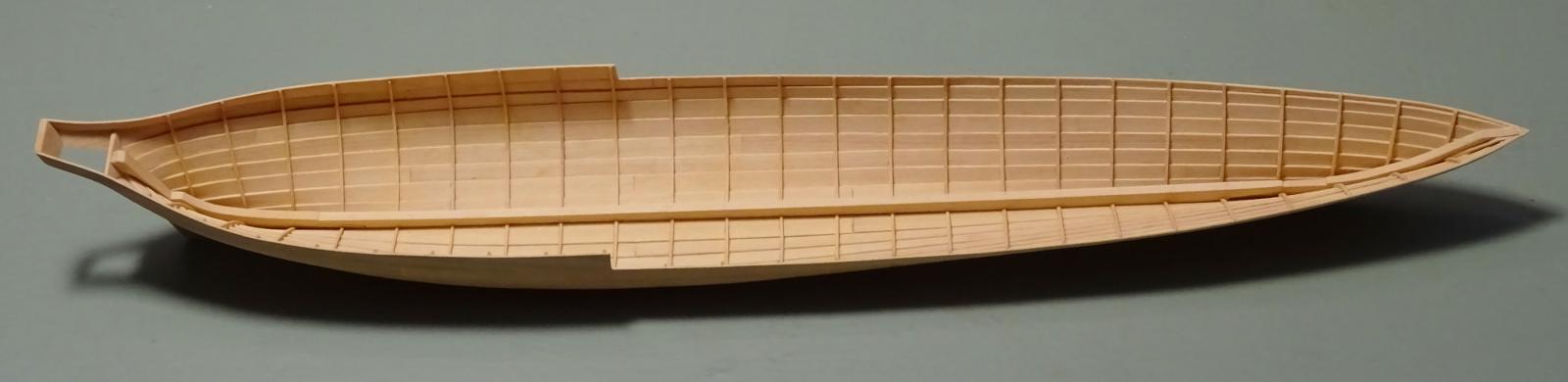
Thanks so much, everyone. A footnote: I fully expected the shell and frames to have spread until the internal members such as thwarts are fitted. This has proved not to be the case so far: the hull is 'on spec', with an overall beam of 6' 1½" (6' 0" moulded, plus 1½" for the planking). We'll see if this is stable when I come back to the model.
- 641 replies
-
- 7
-
-
- greenwich hospital
- barge
- (and 1 more)
-
Just catching up on your log: lovely work!
-
Even a shallow bowl of water in the shop might help things, Ben. Ideally a humidifier is best, but it's better than nothing. Varying humidity due to seasonal change is the enemy of wooden models. Try to keep things relatively stable year round.
-
Nice! She is looking beautiful, Michael.
-
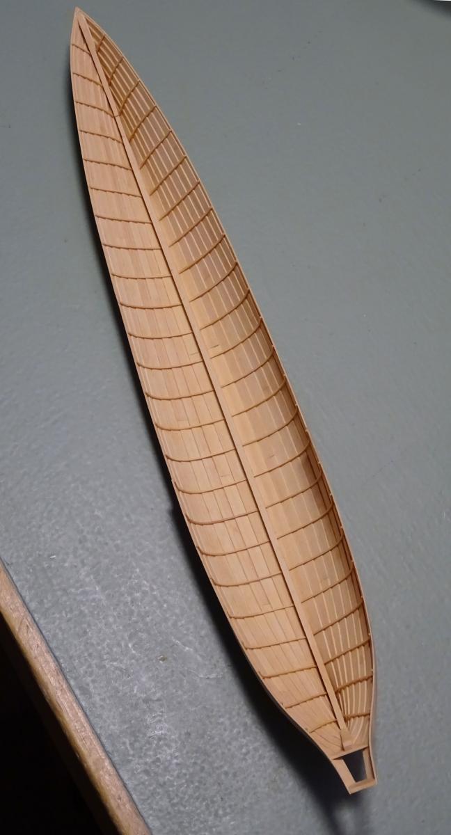
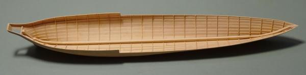
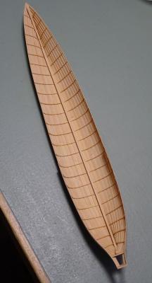
This will be the last update for a few days: the frames have now all been bent in. I'll be back in a week or so. Thank you all for following and liking this log.
- 641 replies
-
- 50
-
-
- greenwich hospital
- barge
- (and 1 more)
-
Remo: I've seen your beautiful work and you are under-selling yourself. I'm trying to be in your league!
- 641 replies
-
- 9
-
-
- greenwich hospital
- barge
- (and 1 more)
-
Cutter Cheerful 1806 by rafine - FINISHED
druxey replied to rafine's topic in - Build logs for subjects built 1801 - 1850
Looking good, Bob!- 525 replies
-
- 4
-
-
- cheerful
- Syren Ship Model Company
- (and 1 more)
-
That sounds very convincing, Glenn. The discussion and process of arriving at this conclusion I found most interesting.
-
I have no idea, as it will depend on the specie of wood you will be using, Steven. You will need to experiment with both moisture and heat.
- 641 replies
-
- 3
-
-
- greenwich hospital
- barge
- (and 1 more)
-
Frégate d'18 par Sané , la Cornélie
druxey replied to JohnE's topic in CAD and 3D Modelling/Drafting Plans with Software
John: did you receive my PM from the other day? -
Beautiful work, as ever. Thanks for the early treat on Friday instead of Saturday! Enjoy your family weekend. Still working on the assumption of quadruple boilers?
-
Excellent method and result, Mike. Well done!
- 452 replies
-
- 3
-
-
- cheerful
- Syren Ship Model Company
- (and 1 more)
-
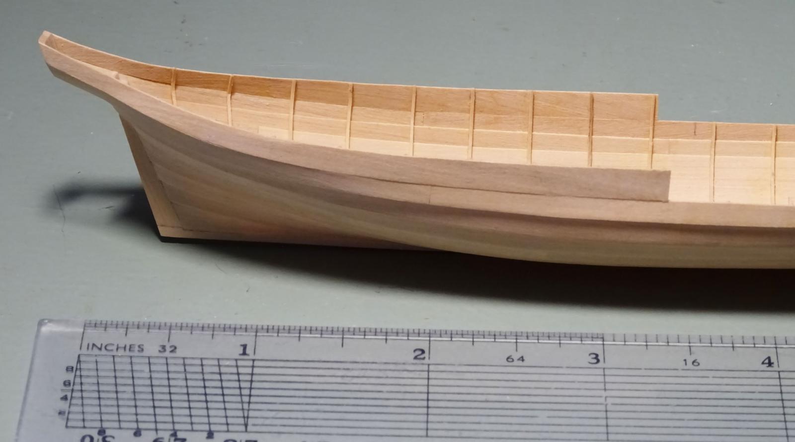
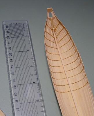
Aft frames are now in, with some fine adjustment still required. A ruler is included in the photos as requested.

- 641 replies
-
- 35
-
-
- greenwich hospital
- barge
- (and 1 more)
-
True enough, Ed. But for most builders, they would be more concerned with the external appearance of the framing.
-
Glue 'em damp, and clean up any excess glue with a damp brush, Ed.
- 641 replies
-
- 9
-
-
- greenwich hospital
- barge
- (and 1 more)
-
Ed, have you tried bending frames using moisture and a thermostatically controlled iron?
- 3,618 replies
-
- 8
-
-
- young america
- clipper
- (and 1 more)
-
Ed: The frames are bent in wet, without any heat necessary. They are of such small dimension that this is easily accomplished under slight compression to 'spring' them into place.
- 641 replies
-
- 6
-
-
- greenwich hospital
- barge
- (and 1 more)