druxey
-
Posts
13,355 -
Joined
-
Last visited
Content Type
Profiles
Forums
Gallery
Events
Everything posted by druxey
-

HMS Naiad 1797 by albert - FINISHED - 1/48
druxey replied to albert's topic in - Build logs for subjects built 1751 - 1800
Superb work, Albert. Keep those progress photos coming! -
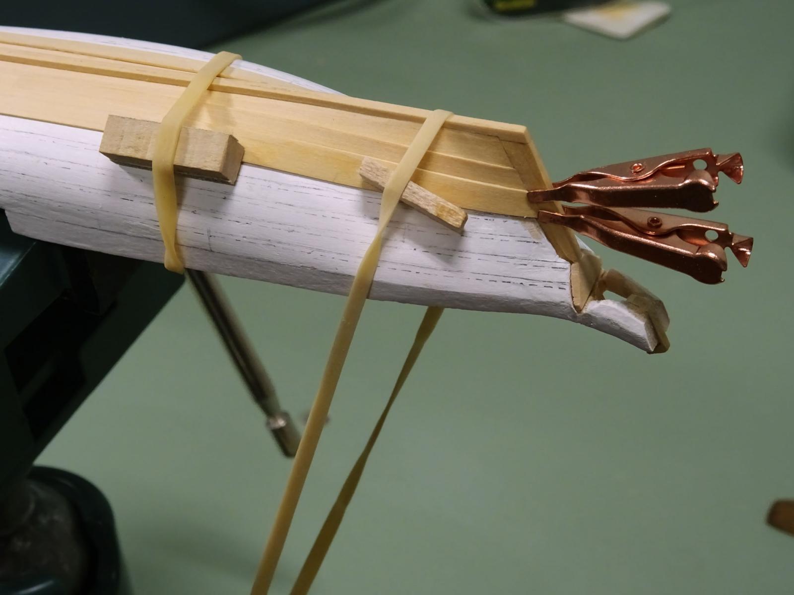
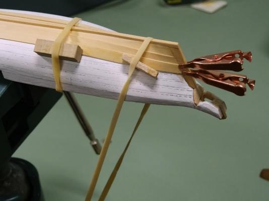
Three strakes a side completed now. Rubber bands and small soldering clips make fine hold-downs while roughly shaped planks are drying out.
- 641 replies
-
- 43
-

-
- greenwich hospital
- barge
- (and 1 more)
-
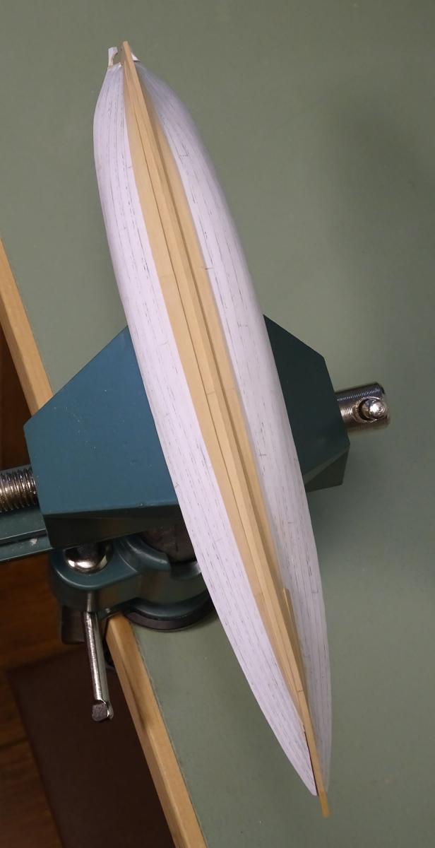
Thank you, Mark! Jim: the strength of the assembly at this stage is surprising, even though the individual parts are so flimsy. If the planks are cut accurately so that there is no stress in the hull, it will not distort. In past experience, sometimes the breadth will expand slightly when the shell is complete, but this is easily corrected when the internal elements are added, producing a very strong model indeed. The barge I'm modelling is not the Prince Frederick's one in Mark's photos: this one, while similar, has far less carved work. However, it will be a lot of fun to do when I get there!
- 641 replies
-
- 7
-
-
- greenwich hospital
- barge
- (and 1 more)
-
Nice details, Mark. Thank you. The carved works are wonderfully executed. The rowing benches on these barges do have a central element to them. The items I'm particularly interested in are the standards supporting the ends of the thwarts and whether there are also supporting standards above the transom. These cannot be seen on the usual photographs of the barge.
- 641 replies
-
- 2
-
-
- greenwich hospital
- barge
- (and 1 more)
-
I smiled at the mention of gummed brown tape. This material was used to 'plank' a bulkhead style model I made when I was about ten or eleven years old. The result was much less successful (the bulkheads were too far apart) than your use of it in making some very nice mast hoops.
-
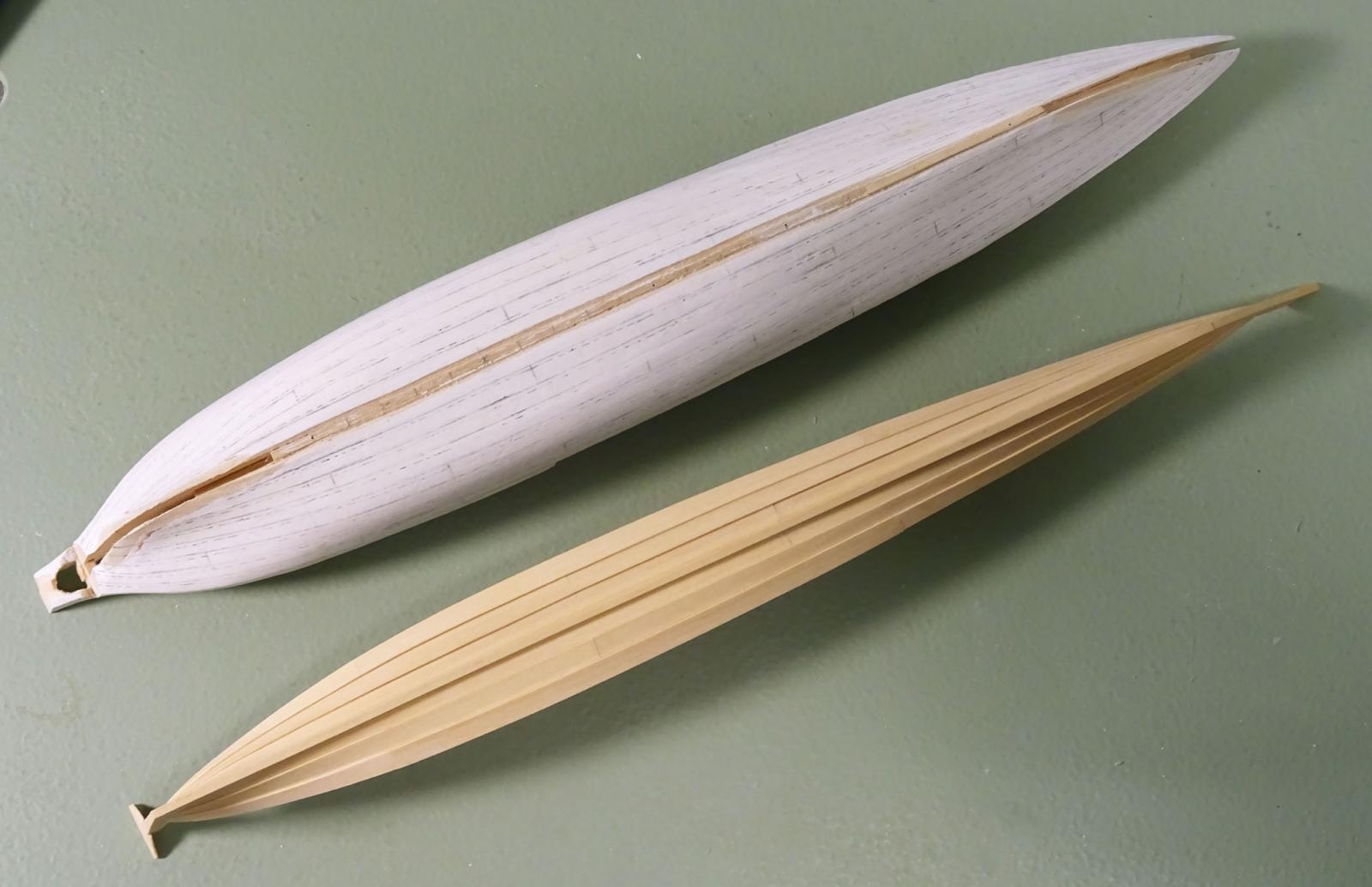
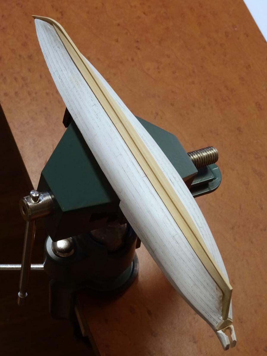
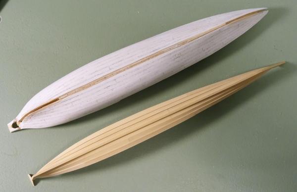
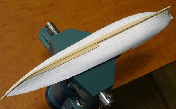
The second strake is in on the port side. One can see the gain at the bow and stern, as well as how the boat keeps its shape when taken off the plug. From here on it is simply a matter of spiling and shaping each plank as I work up (down!) to the sheer strake. All one need do is make sure to conform to the mark-out on the plug.
- 641 replies
-
- 36
-
-
- greenwich hospital
- barge
- (and 1 more)
-
Frégate d'18 par Sané , la Cornélie
druxey replied to JohnE's topic in CAD and 3D Modelling/Drafting Plans with Software
Only switch from x if there is compelling and overwhelming evidence from y! That set of lines looks very nice, John. -
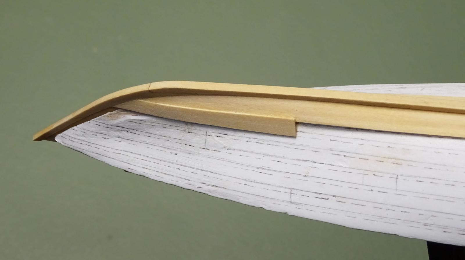
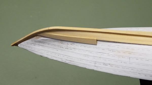
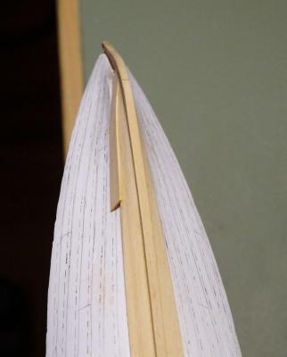
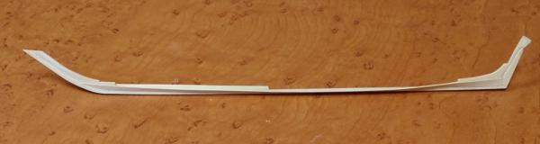
Mark: if you have detail photos of the interior of the forward part of that vessel and near the tiller, posting those would be very helpful. Thanks for the kind offer. Yes, these crafts were very lightly built but surprisingly strong. Think of them as predecessors of today's 'eights' rowing shells. These two photos show how the lap disappears into the rabbet at the bow. The second strake also has a rolling bevel that fits the one on the edge of the first strake. You can also see that there is no gap along the lap, as the bevel that was sanded in takes care if this. PVA glue was applied with a very small brush and any excess cleaned up immediately.
- 641 replies
-
- 31
-
-
- greenwich hospital
- barge
- (and 1 more)
-
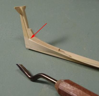
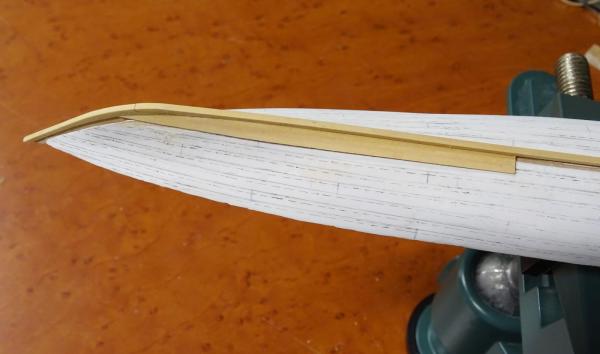
Here are a couple of photographs of the land - the bevel - being sanded on the edge of the garboard and of the gain at the end of the rabbet (arrowed). The gain is basically a rolling bevel. It ends at 45 degrees so that the next plank will come in flush at the rabbet. Essentially clinker becomes carvel over the last 9" or 12" of the strake.
- 641 replies
-
- 29
-
-
- greenwich hospital
- barge
- (and 1 more)
-
Great stuff, Glenn! The original designer of these flywheels was very ingenious. To reproduce these in miniature you also had to be!
-
As Oscar Wilde said, "You will, you will," Michael!
- 641 replies
-
- 6
-
-
- greenwich hospital
- barge
- (and 1 more)
-
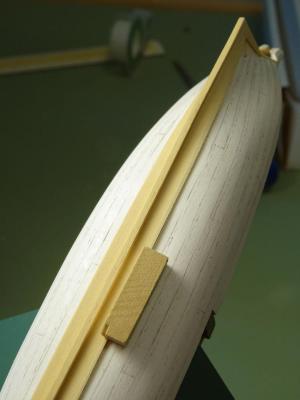
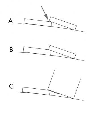
A little more time was spent on completing the starboard garboard strake. The next step is to shape the lands for the second strake of planking. If one were to omit this step, the second strake would not have any gluing surface and there would be a gap under the strake, A. Obviously, a bevel is required. It varies in angle along the strake according to hull curvature, B. To cut this accurately, I took some scrap wood the width of a strake and rubber cemented some 220 grit sandpaper along one edge, C. Keeping the 'safe' corner of this along the mark-out of the second strake's far edge, it is easy to shape the correct bevel along the installed strake. The next instalment will show this completed. A note: I found the short pins under the keel not very effective in holding the keel straight, as the keel kept popping off. On a another long narrow hull I would drill the pins all the way through the keel. A digression: One side effect of modelling an open boat at this small scale is the amount of wood required to build it. Very little is needed, making this a very economic exercise in materials, but not in time.

- 641 replies
-
- 44
-
-
- greenwich hospital
- barge
- (and 1 more)
-
Michael: I cut the stock several thou over-thick on a Byrnes saw with a micrometer adjustable fence. I then process it through his thickness sander to within .004" of finished dimension. A fine sanding block removes sanding marks and completes the prepared stock. The leaves I'm using are just under ¾" wide. George: gesso is the (usually) white compound artists use to prime canvases. These days it has an acrylic base. Once dry, one can sand it to a very smooth surface. Any reputable art store will carry gesso. (The word is pronounced with a hard 'g', as in 'jesso' - or 'George'!) Thanks again for the 'likes', folks.
- 641 replies
-
- 10
-
-
- greenwich hospital
- barge
- (and 1 more)
-
THE 74-GUN SHIP by Jeronimo
druxey replied to Jeronimo's topic in - Build logs for subjects built 1751 - 1800
Exemplary work, Karl! -
Surprisingly little pigment powder is required to color glue. I prefer to mix a small amount of pigment into paste with water before mixing with white glue. As Ed says, the mix will dry much darker than the liquid glue. Please wear respiratory protection as the pigment powder is very fine and easily becomes airborne.
-
Frankie: lead deteriorates at a rate dependent on the atmosphere and temperature it's exposed to. I've seen lead 'fuzz' in comparatively recent models and still undeteriorated lead in older models. Either way, it's toxic stuff and needs to be handled and disposed of appropriately. I've currently got a model for conservation with about 70-year old corroded lead cell batteries in it. They (and the lead-based paint that's flaking off) go to the hazardous waste disposal site.
-
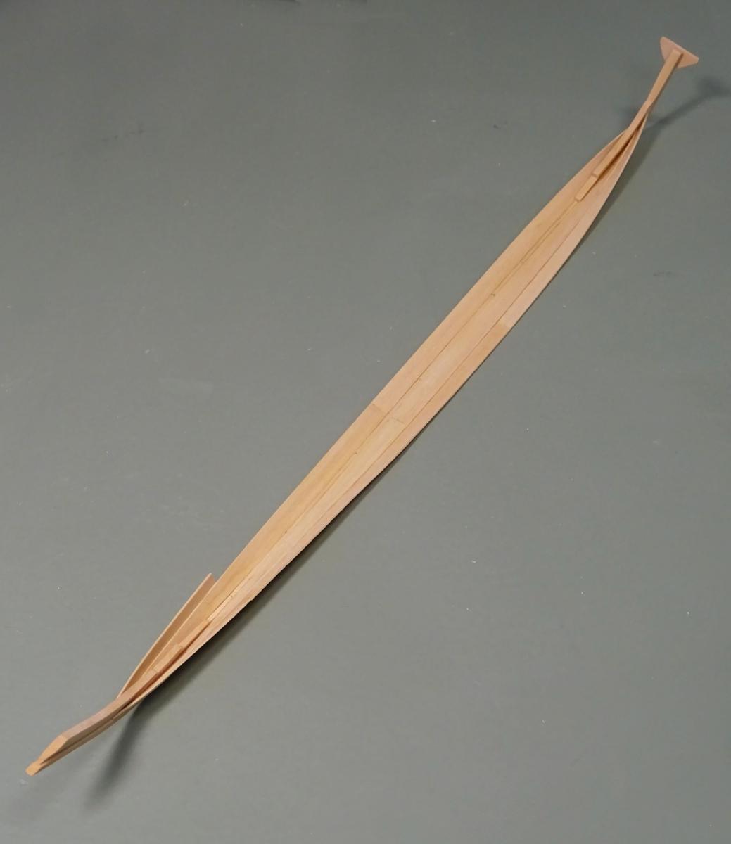
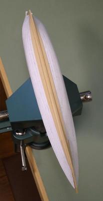
Further progress. The garboard is in on the port side and the forward plank on the starboard. The interesting thing is that, at any point in planking, provided one has spiled and shaped the plank to lie without stress, one can remove the model from the plug and it will retain its shape.
- 641 replies
-
- 43
-
-
- greenwich hospital
- barge
- (and 1 more)
-
Joel: stay with this log and all will be revealed! In short, the laps will be bevelled in a while and gains cut at bow and stern. It will be done just as in full-size practice, but considerably smaller.
- 641 replies
-
- 5
-
-
- greenwich hospital
- barge
- (and 1 more)
-
Sweet! She's looking good.
-
If that was your first attempt at carved lettering - well done, Michael! And that you used a simple #11 blade rather than miniature carving tools is even more remarkable.
-
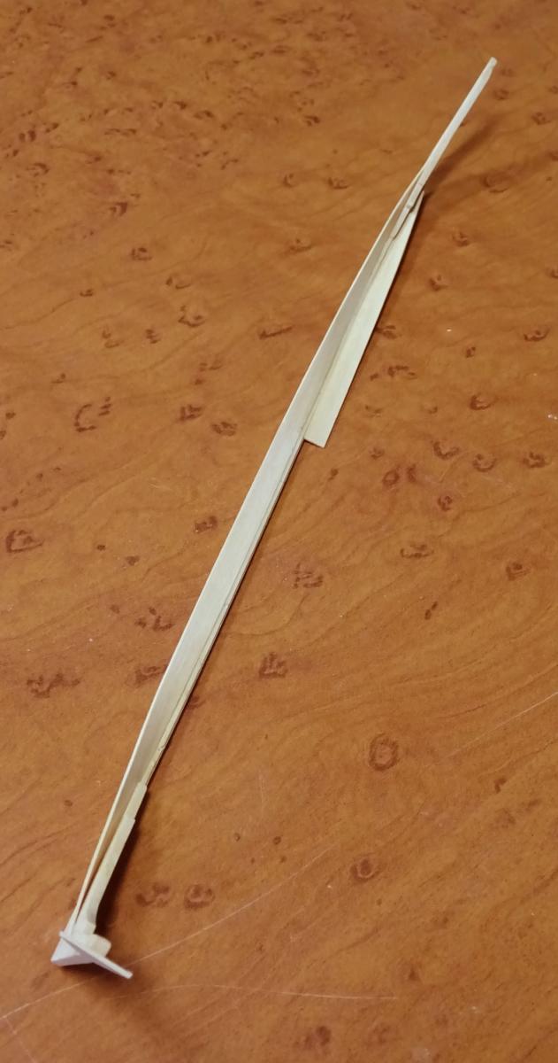
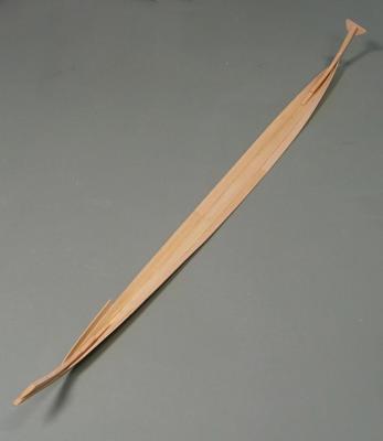
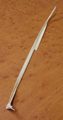
Thank you, gentlemen all. Finally had some quality time on the model. The first garboard plank is now spiled, cut, shaped and fitted. The stock is thin enough to cut with a sharp scalpel blade. The twist was achieved by cold wet bending and holding in place using rubber bands until dry. Castello takes more persuasion to bend than holly. Once the plank was dry, it was glued in place. I needed to cut back the plug more at the bow to allow the plank to land nicely in the bow rabbet. One plank down, many more to go!
- 641 replies
-
- 36
-
-
- greenwich hospital
- barge
- (and 1 more)
-
A two year old? What were they thinking???? Anyway, both models are a good restoration challenge and I'm looking forward to seeing them returned to their former glory. Good luck with them.
-
That is exactly so.
-
White Paint Issues
druxey replied to rynmss's topic in Painting, finishing and weathering products and techniques
And is the paint well stirred? In some paints the pigment tends to settle out fairly quickly.