


Bedford
-
Posts
1,261 -
Joined
-
Last visited
Content Type
Profiles
Forums
Gallery
Events
Posts posted by Bedford
-
-
Mark, I went to the Boat Warehouse on Monday and they have a model Ranger too, not a patch on the ones you build though.
Meanwhile, I'm in Rathmines on Lake Mac and building my 2nd 12 inch the the foot model
- KeithAug, Scottish Guy and Jack12477
-
 3
3
-
-
Yes, I've seen and held Johns previous model and it's just beautiful. The man does excellent work!
- mtaylor and FriedClams
-
2
-
Well done! She looks brilliant out there
- Keith Black and Ian_Grant
-
1
-
 1
1
-
I haven't used it on any models yet, I'm too busy taking Sheriff Brodys advice and building a bigger sail boat.
- Mark Pearse and mtaylor
-
 2
2
-
I use PVA and a little C.A. where applicable unless it's going to get wet in which case I use epoxy. Used WEST on the first RC one I did and it's a nightmare, the stuff goes off while you're mixing it!
I now swear by Bote Cote. No nasty chemicals and no hardening anxiety, it gives plenty of work time to get a good job.
-
Nice to see you making some progress mate, You'll have to elaborate on the restoration project. There are a lot of beautiful, and some quite large, ship models there.
- Keith Black, mtaylor and FriedClams
-
3
-
Hey Mark, nice to see some progress.
What epoxy are you using and do you know the tricks of how to easily work with the stuff?
If not feel free to ask
- Jack12477 and Mark Pearse
-
2
-
That's a great demonstration, lovely to see it moving with all oars.
If you look at the rudders on RC sailboats you'll find they are normally way oversize because scale size isn't enough so if you want scale rudders you might need to get creative like, and it's a sneaky and historically abhorrent solution but I'm sure you could get a small bow thruster to slip into probably the stern, for proper movement, to help it turn.
- Javelin, mtaylor and Glen McGuire
-
2
-
 1
1
-
All that beautifully intricate work foiled by cheap crap auxiliary components. It drives me mad that I can't buy good quality things like that anymore
- Ian_Grant, mtaylor and Glen McGuire
-
3
-
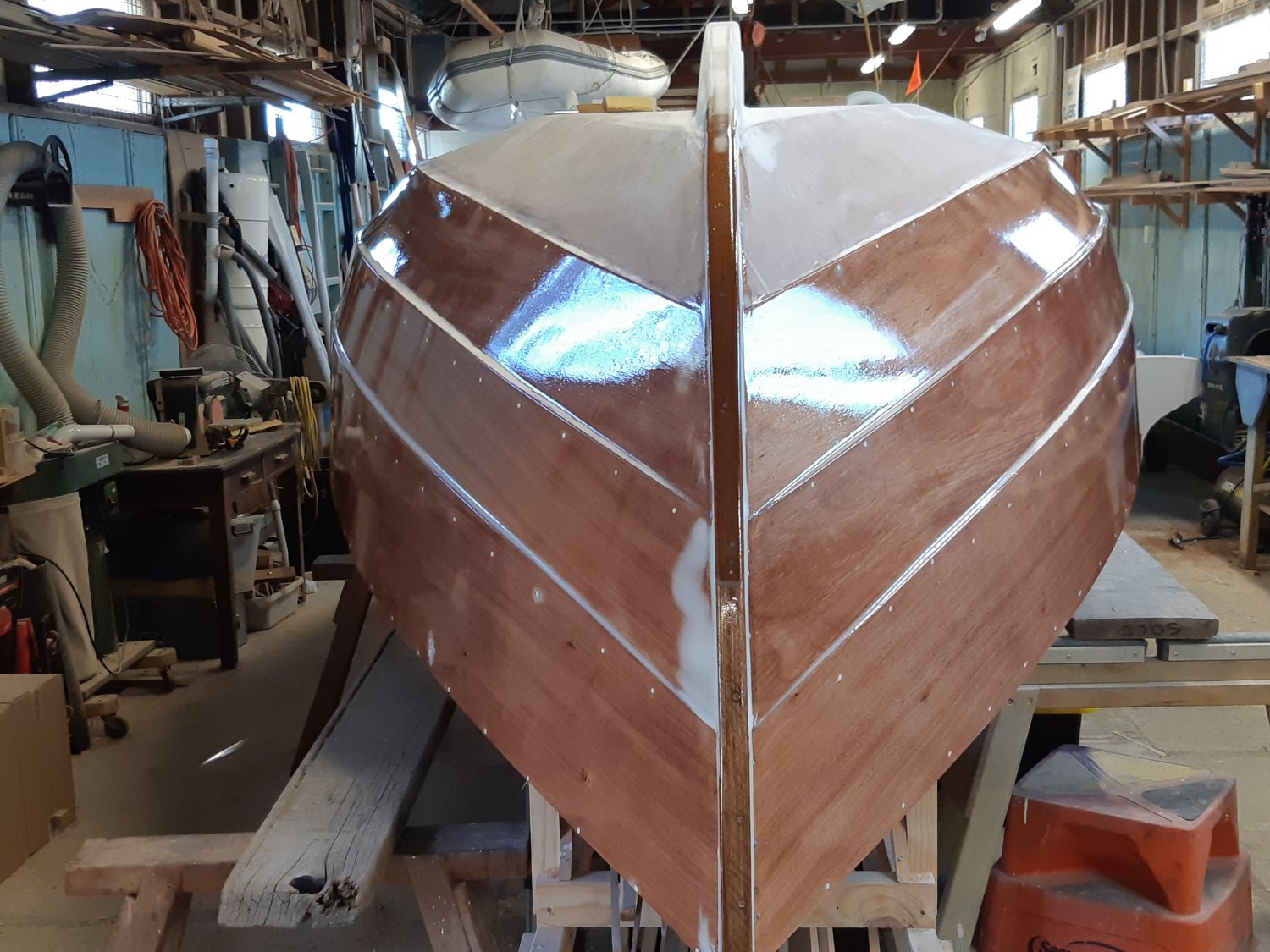
It had to be incredibly frustrating having gone to great lengths to get the planking so good only to see it open up. It looks brilliant now but I'd be inclined to get that paint on as a matter of urgency to seal it before the moisture level changes again.
- FriedClams and mtaylor
-
2
-
I love the lines of a Ranger, looking good Mark
-
The Couta Boat is considered such an icon of Australian nautical history that there is one at the Australian National Maritime Museum.
Nice to see a model build of one.
- Glen McGuire, mtaylor and Louie da fly
-
2
-
1
-
On the subject of rudders, I wonder if they were, in reality, more trim tabs than actual rudders, as is the case in tall ships in which the set of the sails does most of the heading work.
Having had the helm on a 4 man row boat I can tell you the rudder only has any real effect when the oars are out of the water so you end up with a segmented turn.
-
I was thinking the same as Grant, once you get the second tier of oars it should speed up, yes it's slow off the mark but then it should be.
Before worrying about oar size I'd suggest you work out the theoretical hull speed "Hull speed can be expressed as a simple mathematical formula 1.34 X the square root of the length of the waterline (HS = 1.34 x √LWL). For instance, if a cruising sailboat has a waterline length of 36 feet, she should be able to sail 1.34 x 6, or approximately eight knots."
Then work out the scale speed of the boat and take it from there, mind you it's doubtful such a big rowing boat would have ever attained hull speed.
As for the amount of ballast, I'd leave that as is too for now because water doesn't behave in a scale fashion so if you make it lighter it might get tossed around like a cork. The ballast helps her ride in a more scale manner.
-
-
I nearly forgot about this one Mark. Glad to see some progress!
I'd heard Maluka did the Fastnet, he's keen shipping her all the way over there for a race!
- thibaultron and Mark Pearse
-
2
-
Nice project!
I've come to the party a bit late but I have a few epoxy/fiberglass tips that may be useful later or to others.
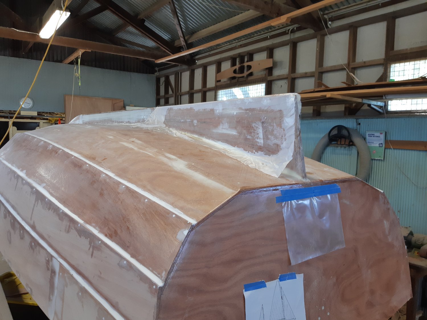
I'm currently building a 17' sail boat, yes, full size and I've made wooden RC boats.
On the real thing I fibreglassed the bottom for mechanical protection and I worked a sheet of "peel ply" over it, this gives a uniform finish like a fine fabric weave one you pull it off after curing. You could use it on model ships if you really needed to 'glass the hull as it greatly reduces the need for sanding. However on the subject of sanding, the topsides of my current build are merely sealed in epoxy and will be painted and an old shipwright gave me the best tip ever. Use a cabinet scraper rather than sanding! It's so much quicker and easier and you can control what and how much you take off. I've been to the boatshed this morning and scraped the whole topside of the boat in about 2 hours leaving just a quick sand to go.
Yes the frames are a long way apart on this model and you have found an issue with that. In that case I think I would have cut patches of light fibreglass to fit between the frames and epoxied them in on the inside. Hopefully the thickened epoxy you've added will do the job but a sanding filler in epoxy makes it thicker but weaker. You can buy other fillers that will retain the strength. I hope I haven't worried you with that but if I were you I'd be floating it again with enough ballast to bring it to its lines and leave it for a few hours. Better you find a failure in the tub than on a lake.
-
5 hours ago, Keith Black said:
Steve, she's a beautiful little rig. Wish I was there to help as I'd love to make or help make something that neat and pleasing to the eye.
Keith, I mentioned a while back that I had to find a new place to live and a big deciding factor in moving here was the Lake Macquarie Classic Boat Association. A "Mens Shed" type arrangement, we are a group of like minded retirees that like messing around with small boats and we can build boats for ourselves with the help of many hands including a couple of shipwrights. It's a great environment and there's always something new to learn be it boat related or not.
- michael mott, Mark Pearse, Cathead and 1 other
-
4
-
11 hours ago, Snug Harbor Johnny said:
Hmmmm, I suppose it would be too much to try and have the oars-persons 'feather' the blades on the back stroke.
I doubt they used rowlocks in those days or those ships, more likely thole pins or similar which don't allow feathering.
- Glen McGuire and mtaylor
-
2
-
2 hours ago, Mark Pearse said:
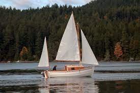
a sailing boat?
It's a Selway Fisher Ptarmigan 17 as redrawn in the glued lapstrake format with a yawl rig
- Cathead, Ian_Grant, GrandpaPhil and 2 others
-
5
-
-
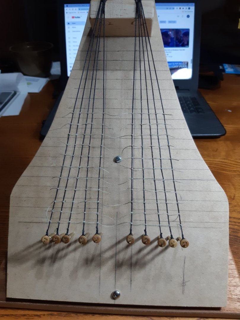
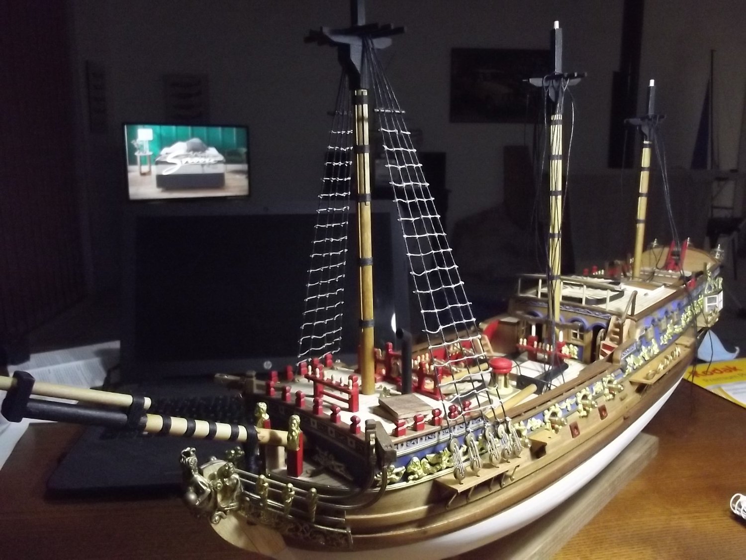
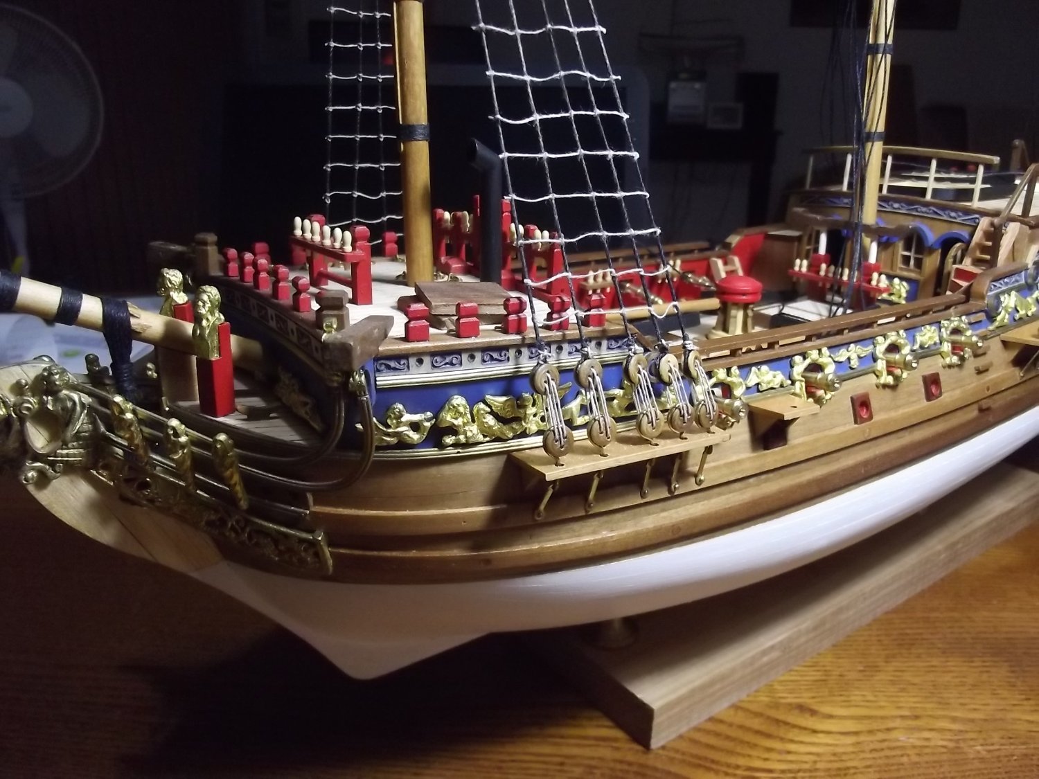
Well it's been quite a while between drinks on this build, mainly because I just haven't been happy with the chain plates and couldn't see a solution so I walked away. I have also been somewhat engrossed in a slightly bigger project.....
I found a viable solution to the chain plate issue and was given an Amati shroud rigging jig which I promptly threw away but kept the pins. It didn't suit the lay of the shrouds on this ship and what's the use of a jig that doesn't let you mount the dead eyes until it's off the jig. I centre drilled each pin and inserted a length of 1mm brass wire so I could measure up the shrouds, drill holes in a jig for the pins and fully create the shroud including dead eyes before the rat lines. It's a lot easier than doing them in situ.


-
Just another thought on the lead shot ballast, if you pour it in loose and spread it around to where it works best you can then pour a little epoxy over it to secure and seal it.
- mtaylor, Glen McGuire and Ian_Grant
-
2
-
1


Ranger type yacht by Mark Pearse - 1:12 - SMALL
in - Build logs for subjects built 1901 - Present Day
Posted
I love that last shot, beautiful planking.
More use of Huon Pine, lovely stuff!