HOLIDAY DONATION DRIVE - SUPPORT MSW - DO YOUR PART TO KEEP THIS GREAT FORUM GOING! (Only 53 donations so far out of 49,000 members - C'mon guys!)
×


ianmajor
-
Posts
784 -
Joined
-
Last visited
Content Type
Profiles
Forums
Gallery
Events
Everything posted by ianmajor
-

Cutty Sark by NenadM
ianmajor replied to NenadM's topic in - Build logs for subjects built 1851 - 1900
Nenad, great work. You have given us a genuine thumbnail illustration as well.- 4,152 replies
-
- 6
-

-
- cutty sark
- tehnodidakta
- (and 1 more)
-
Greg, Fantastic work on such a small scale. On your upside down question, a few logs have been opened on this. Dee_Dee has looked in to this. Here are a couple of entries that might help. <Link to "Photos in log sideways"> <Link to "Photos are loaded and are upside down"> Obviously ignore the advice to turn your screen upside down etc. (Edit) I lifted one of your upside down photos and put it back. It looks even better this way up!

-
Terry, Have a look at Landlubber Mike's technique for furled sails log <link here> . He discusses the best shape of material to use to ensure the furled sail is not too bulky. There are other logs that cover this but Mike's log is a good starting point. It is possible that you may need extra rigging since some kits that are supplied without sails may have a simplified rigging scheme.
-
Ed, Excellent work on the boat - it has given me some useful guidance for one that I wish to make in the near future. Like you I use photographs of my models to identify unseen errors. Also when I am looking at monochrome source photos I like to use a photo edit package to produce a negative. The human eye/brain can easily differentiate small details in light areas but does not pick out detail in dark areas of a photo quite so easily. The negative makes the dark areas light resulting in all sorts of details revealing themselves. Useful things these cameras and PCs!
- 3,618 replies
-
- 8
-
-
- young america
- clipper
- (and 1 more)
-
Ron, It is well worth the wait. Thanks for sharing your knowledge.
-
Looking very good. Those two motors will give a lot of power - I can see the boat will be high performance.
- 184 replies
-
- 3
-
-
- ruby & arthur reed
- lifeboat
- (and 1 more)
-
Dan, Great work. I struggle to keep up with your updates. Your hands must be a blur when you are modelling!
-
Cutty Sark by NenadM
ianmajor replied to NenadM's topic in - Build logs for subjects built 1851 - 1900
Nenad, You are right, small scales force compromise. Sad because that smaller version of the pin rail looks superb. A lovely piece of work.- 4,152 replies
-
- 5
-
-
- cutty sark
- tehnodidakta
- (and 1 more)
-
Good Heavens Piet, is there anything you can't do?! Beautiful carving. My money is on the croc winning.
-
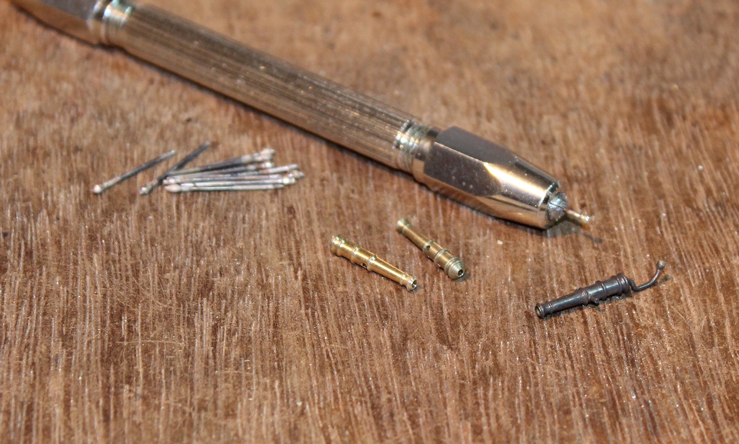
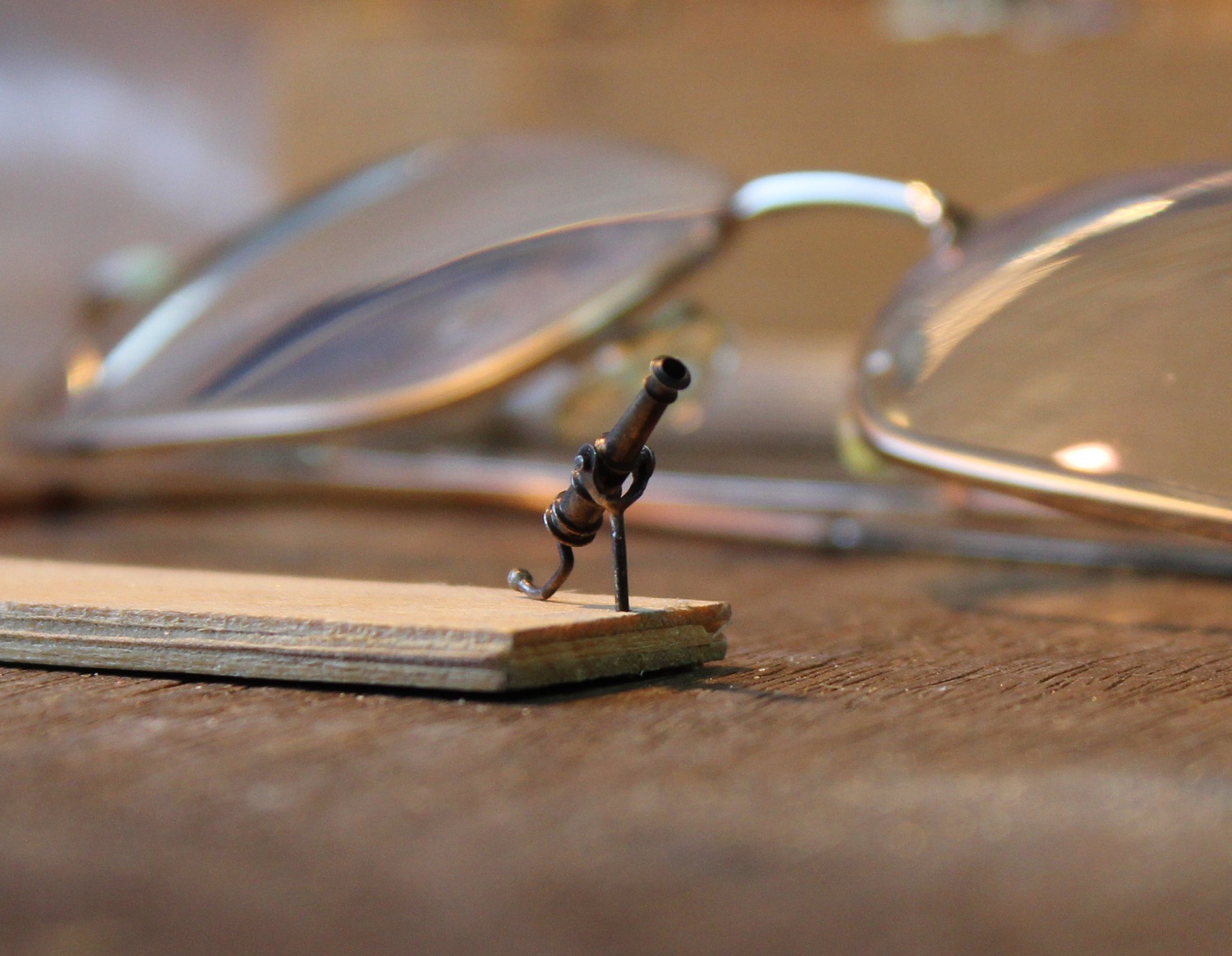
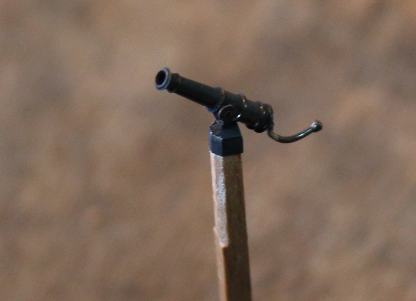
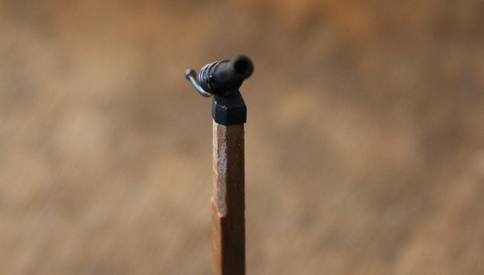
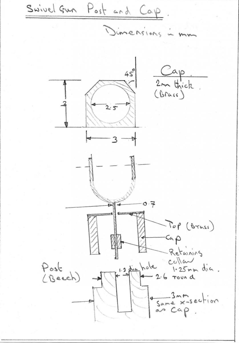
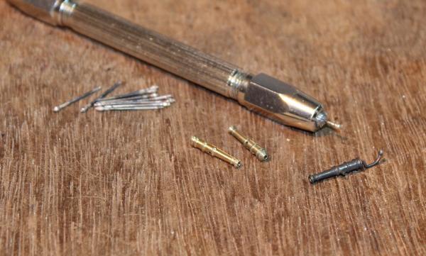
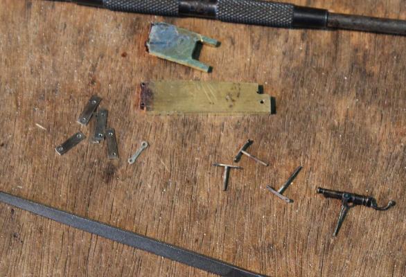
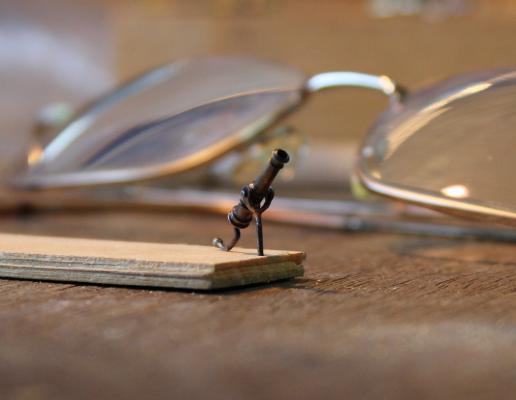
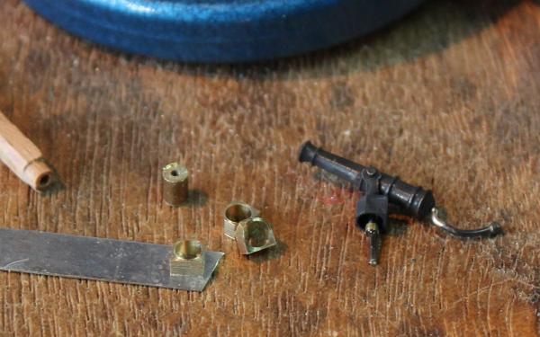
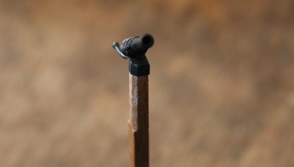
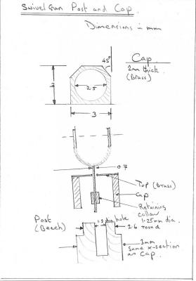
I have finished the fixed caps on both sides of the quarter deck and am preparing the open rails. Some of the main supports are the swivel gun posts so I started with these. For barrels I used Caldercraft 1:64 scale 0.5 pounders. At 14mm long they are about 2mm too long but I thought they would be OK. They are nicely turned but where they had been parted were a little rough so some tidying with a fine file was needed. At the rear of the barrel is a hole. To represent the handle I used 0.7mm nickle silver wire. For the knob on the end I cut 0.5mm lengths of 1.25mm brass tube which I threaded on to the wire and fixed with a blob of silver solder. A little tidying with the file produced the final ball shape. The wire was trimmed so that when fitted it protruded by 8mm from the rear of the barrel. The trunnions were more 0.7mm wire. All these items were silver soldered together, the handle shaped and blackened. To make the "U" shaped supports I produced a filing jig similar to the one I used to make the chain links for the pump <here> . In this case I produced one "link" per gun with holes 6mm appart. I silver soldered a length of 0.7mm nickle silver wire to the middle of these then curved the links in to a "U" shape. These were blackened and fitted to the barrels. The trunnions on the barrels had been left slightly long so with the supports in place I filed them to length. This produces small burrs which lock the supports in place. The following photo shows the first barrel mounted on a temporary piece of wood. Some of the blacking had not taken very well so I cleaned it up and repeated the process to better effect. To get the construction of the post and cap right I produced a rough diagram: I am using 3 x 3 mm beech for the posts which will be shaped in to a "squared D section". The caps will be brass with the same cross section. The caps will have a circular hole in the centre to fit on the end of the post. The caps were made from 6mm diameter brass rod. I first mounted it in the lathe and drilled the centre 2.5mm. This was then moved to the dividing head on the mill to machine it to the "D" shape. The faces were at 0, 45, 90, 135, 180 and 270 degrees. This was returned to the lathe and each cap was turned off 2mm long. Each cap was then soft soldered on to a sheet of 0.3mm nickle silver to close the top of the cap. A 0.7mm hole was then drilled in the middle of this to take the cannon. The cap was blackened. The cannon was then fitted to the cap and retained in place by glueing a short length of 1.25mm tube as a collar on the end of the support rod avoiding gluing it to the cap. The top of the beech post was drilled 1.3mm to clear this collar. The cannon and cap were temporarily fitted to the top of the post. When permenantly fixed it will swing from side to side and up and down - no doubt someone will try it in future! Now to finish off the other 11 swivels.

-
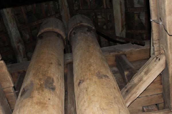
Mark, Thanks for the information. That was an interesting discussion we had. I have had a few distractions from my modelling recently one of which may be of interest to modellers of older sailing ships. I visited Dunham Massey house with my wife. It is a large house and grounds which is a few miles south of Manchester (UK) which owned by the National Trust (of which we are members). My wife found the house and gardens interesting. However I had a ferret around a small dark building called the "Well House" which was the original source of water for the main house. Inside are a pair of elm tree pumps of a similar design to those used on ships which would have been used to lift water from the well. Below is a photo that I took of them. It is a view up the elm wood pipes towards the roof of the building. The right hand pump still has its handle which is visible in the photo. I could not see a handle on the other. There appear to be slots in the sides near the top from which the water would have emerged in to a header tank for the house.
-
Hello Thistle17 from another Unicorn builder. As you have noted the Corel Unicorn makes a nice model but is not very accurate. The Corel history for this ship is dubious to put it mildly and seems to confuse the identity of a few ships called Unicorn. I agree with your assessment of the hull. I am working on the basis that the Chapman plans are of the 1748 Unicorn. Some info on this ship can be seen <here>. This states that it had 24 off 9 pounder guns on the upper deck and 4 off 3 pounder guns on the quarter deck. It also had 12 swivel guns. It is my view that Chapman did not design the Unicorn but simply documented it after it was decommissioned. The original plans are missing. It is a member of the Lyme class. The Lyme plans still exist in the NMM. The layout of the quarter deck/fore deck does not look accurate to me. So I have modified mine to have an open waist area - which I believe looks a lot better. There are a few Unicorns at various stages of construction with logs on this site. You will also find some completed models in the gallery. Good luck with your build. I will be following it with interest.
-
Rigging tools how are they used
ianmajor replied to Telp's topic in Modeling tools and Workshop Equipment
Telp, On the "how to use" question, have a look at a log by Peter Visser in the "Masting, Rigging and Sails" section which gives a nicely illustrated description on the use of (at least some of) this type of tool. <Link to log> -
Moony, Interesting as you say that a boiler explosion sank the steamer. Looks like it was tube failure that caused it leaving the shell intact. The tube failure would probably have blown the burning fuel out of the grate in to the ship. Seriously bad news for the stokers.
-
Igor, That is an interesting way to make tiny brass rings. It produces a great result. Can you clear up a few things for me? Is that brass rod (not tube) that you are annealing in the 2nd photo? If so in the 4th photo are you reaming out a hollow in the rod with a broach? I can see that it would be tricky to stop it wandering off centre. Thanks.
-
Excellent Ed. Getting the curves and bends in brass wire at the correct point and the right angles is a whole challenge in itself.
- 3,618 replies
-
- 4
-
-
- young america
- clipper
- (and 1 more)
-
Moony, That is an interesting two cylinder engine you have found but to my eyes looks too modern for the period of your ship. It has the appearance of a two cylinder double expansion compound. The low pressure cylinder has a slide valve, the high pressure cylinder appears to have a piston valve. For your period I would expect the valves to be all slide valves. Is there any indication of the manufacturer of the engine on this ship? If so you could do a search on Graces Guide to British Industrial History < link to Engineer magazine index> which gives access to contemporary engineering publications. An example - from the 6th October 1882 edition of Engineer I found this 1882 two cylinder compound marine engine <link to photo> from F.J. Harker, Stockton-On-Tees. Stockton is close to Newcastle. To me this is the sort of engine to look at. It also looks like the engine outline in your plans.
-
Mike, Nice progress. I am intrigued by the Duplo bricks. Does this mean your children are helping with the build? Or have they outgrown them and moved on to the smaller variety allowing you to play with them when the ship build gets frustrating?!
-
Well Piet, I don't read your log for the modelling but for the education I receive about far flung places and their folklore. Well actually that is not quite true - the anchors are fabulous.
-
Ah yes - it is always a good idea to make sure that your creation can be moved from the workshop. I learnt this when I was young from one of my secondary school teachers. He had taken up sailing as a hobby. For this he built a dingy hull in the front room of his house. When complete it was a beautiful piece of work. Sadly it would not pass through window or door. So to get it out he had to saw it in half!
-
Piet, A very impressive pair of anchors. I agree with you about not polishing the parts until you can see your face in them. To me you have produced a very realistic metal surface by getting rid of any "machine marks" but leaving it (very) slightly rough. Easier said than done.
-
Igor, I am always impressed that your rigging doesn't end up in a tangle - one look from me and thread puts itself in a knot. In your last photos of the ship standing on a block of wood I can see a thin white layer. Is that a piece of double sided tape?