


Gahm
-
Posts
1,217 -
Joined
-
Last visited
Content Type
Profiles
Forums
Gallery
Events
Posts posted by Gahm
-
-
When I look at your planking the first thing I notice is that you did an excellent job planking around the gun ports. That normally is the most tedious job. At least I do not like it at all
 . And if you paint the hull anyway it should not be too difficult to correct the little "discrepancy" at the bow. I am just not too much in favor of your solution #1
Thomas
- EJ_L, FriedClams and hervie
-
 3
3
-
-
Thank you, Dirk and Mike! And thanks for all the likes!
Mike, I turned the chimney foot on my (Taig) lathe out of a small piece of solid brass rod. After the practice I just recently had with the tiny steering wheel spokes this piece was relatively straight forward
Thomas
- CaptainSteve, Stuntflyer and JesseLee
-
3
-
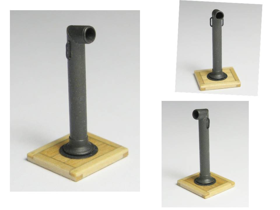
This week I worked on the galley stack. It is built out of a 1/8” brass tube cut at a 50˚ angle, the 2 handles made out of 28 gauge black anodized wire, and the chimney foot, which together with a metal ring in the deck, through which the smoke pipe comes up from the kitchen range, prevents water from leaking through the deck to the kitchen (Charles Davis, “The Built-Up Ship Model”). With the exception of the deck ring all galley stack parts are shown in image 1b. Positioning the handles in the correct locations proofed to be a bit more challenging than I initially thought. After messing up my first attempt I used masking tape, marked the correct handle positions ¼ circumference to the left and right of a central mark and aligned the masking tape with the center of the brass tube of the chimney (image 1a). This led to satisfactory results. The finished galley stack is shown in images 2 – 4.
Thomas
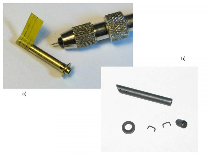
Image 1
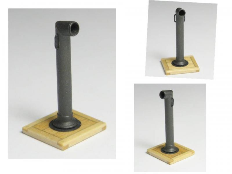
Image 2
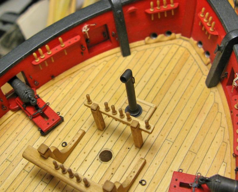
Image 3
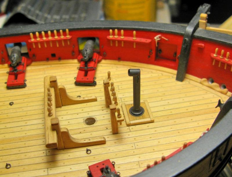
Image 4
- Stuntflyer, jwvolz, JesseLee and 10 others
-
13
-
-
Thank you Dirk, B.E., and Frank for your comments, and thank you Frank for all those likes! If I am lucky the deck of my Syren model at some time will look as nice as Dirk's model, but the "soon" is clearly a bit on the optimistic side
Thomas
- Stuntflyer, foxy, JesseLee and 1 other
-
4
-
Thank you Dirk and B.E.! And thanks for all the likes!
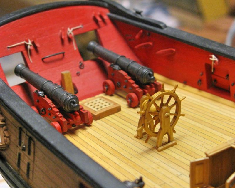
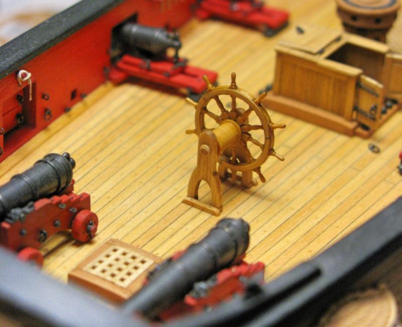
B.E, yes, the Syren has an external tiller rope system. And you are right, there really is not a lot of room for this, especially in light of operating the cannons in a battle. But then it must have been a pretty uncomfortable place for the helmsman in a battle anyway
Thomas
-
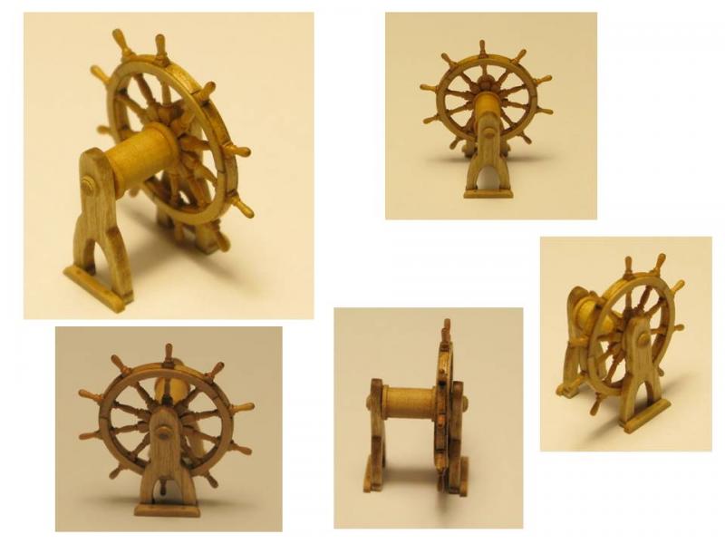
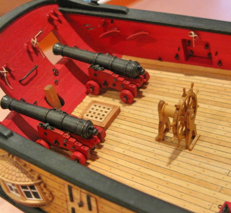
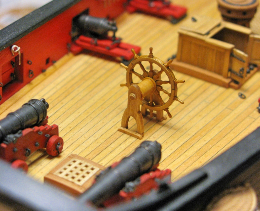
I finished the steering wheel. The drum and the axis covers were turned out of pear wood which was specifically selected for its light color to match the boxwood of the wheel. The 2 frames are the original bass wood parts provided in the Syren kit. The whole assembly was stained repeatedly with Golden Oak wood stain (MinWax).
Thomas
- JesseLee, Dubz, CaptainSteve and 16 others
-
19
-
Great progress, Jesse! It is quite a mile stone to have all the carronades finished. And they turned out very nicely!
Thomas
- CaptainSteve, JesseLee, Piet and 4 others
-
7
-
Thank you for all your generous comments and all the likes!
Chuck's wheel kit is well designed and a pleasure to work with. It leaves enough "modeling freedom" so you can give it your own mark, but as the major parts of the wheel are laser precut it ensures that the dimensions of the wheel turn out correctly - which is not an easy thing at that scale!
Thomas
- CaptainSteve and JesseLee
-
2
-
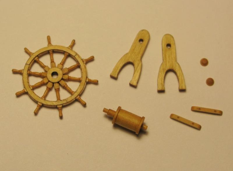
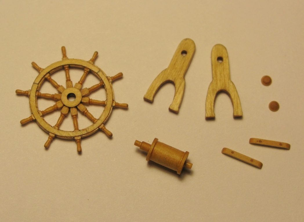
I tried my luck with the steering wheel. As Chuck is now offering such a nice kit I could not resist. Image 1 shows the parts which come with the kit. The building instructions can be downloaded at Chuck’s SYREN Ship Model Company webpage. Following the instructions I cleaned and aligned the little wheel parts in the provided jig (image 2a). Then I deviated a little from the instructions. Instead of aligning and gluing the 3 circle parts on top of the little wheel pieces in the jig I first built me another jig (image 2b and 2c) which allowed me to assemble and glue together the 3 parts to one relatively precise, complete circle. Aligning this circle on the pieces in the wheel jig (i.e. 2 concentric circles on top of each other) was much easier for me than doing it with 3 separate circle parts. The result is shown in images 2d and 2e. Turning the wheel spokes was an act of patience. I chose a spoke pattern which seems to be pretty common and widely spread (image 3). In order to precisely align the spokes in the wheel I built me another circular jig covered with a sheet of paper (glued to the jig) and with a central hole. For ease of handling I mounted this jig in a table 3-jaw-jug. The central jig hole allowed holding a drill piece with the same diameter as the hole provided in Chuck’s jig. So it was pretty easy to align the kit’s wheel jig upside down with the wheel assembly in place on my new jig and lightly glue the wheel assembly to the paper. After removing the (wheel) jig the wheel assembly was perfectly centered on my new jig. The wheel star center piece was also aligned on my jig using the drill (image 4). After this preparation it was fairly easy to glue the spokes in their place (image 4), adding the 2nd circle as well as the central circular cover as described before, and sand it down to the required thickness (image 5). The sheet of paper allowed for easy removal of the wheel from the jig (image 6) using an Exacto knife. All that remained to be done was mounting the wheel with the other side up on the jig using the drill to keep it in place and sand it down to the required thickness. The result is presented in image 7.
Thomas

Image 1
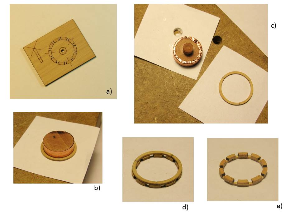
Image 2
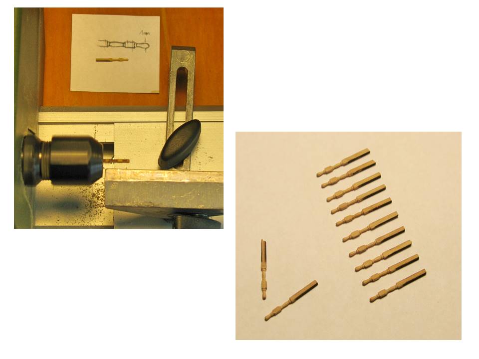
Image 3
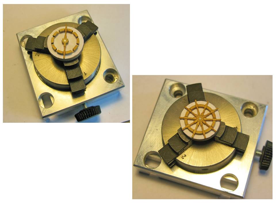
Image 4
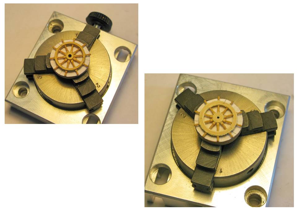
Image 5
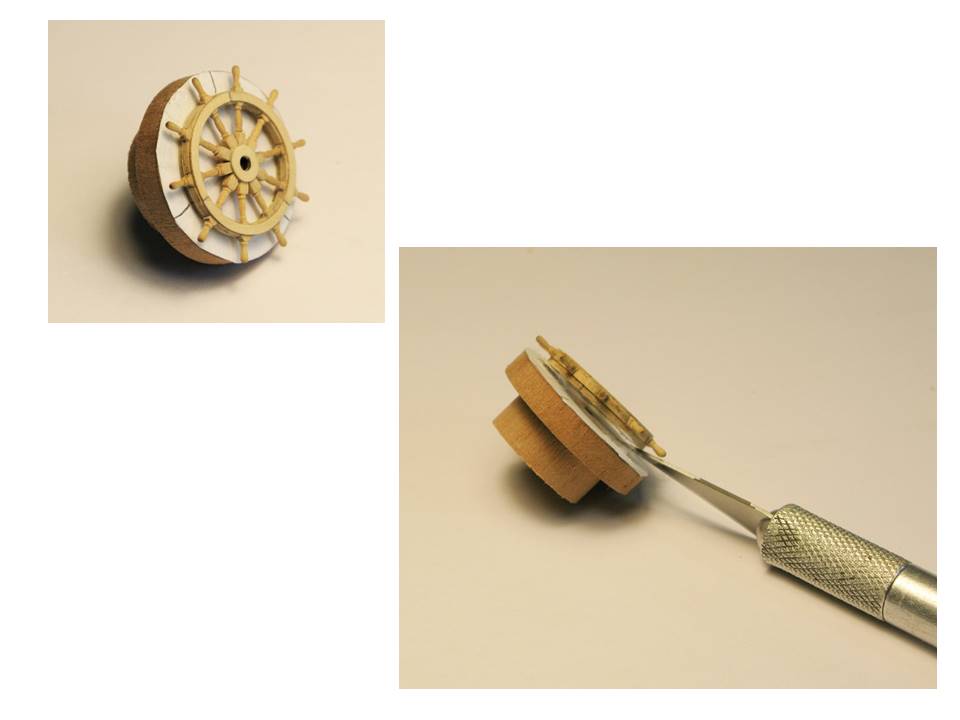
Image 6
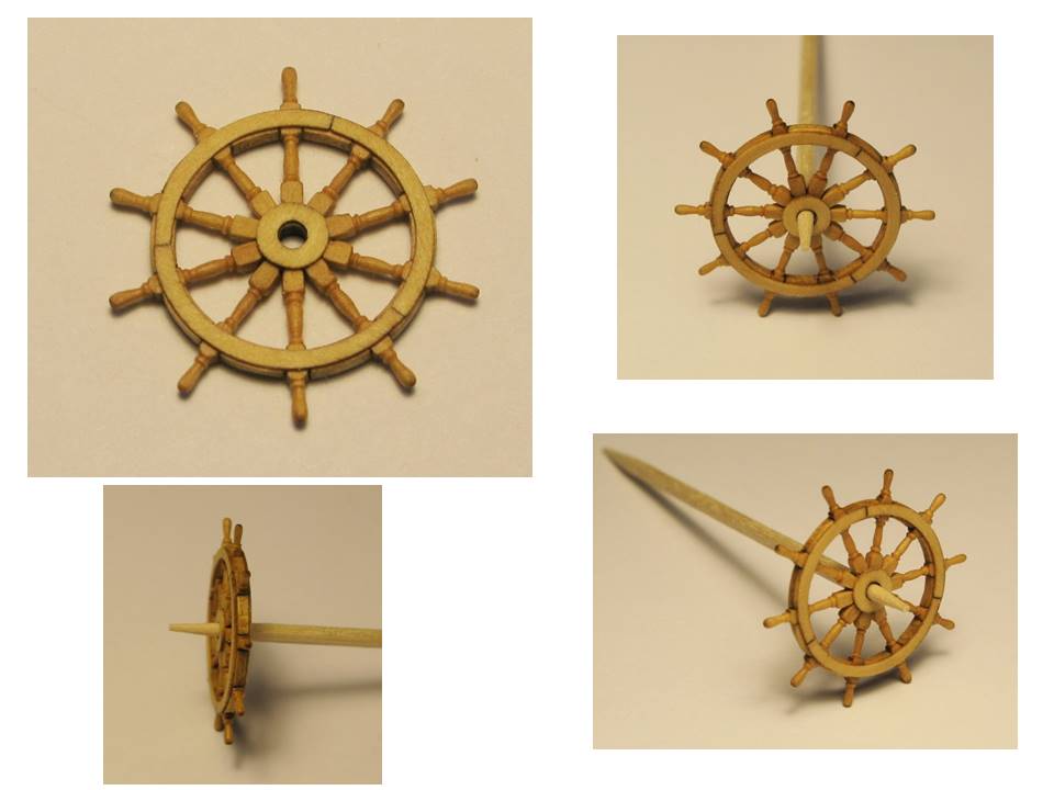
Image 7
- _SalD_, hervie, Chuck Seiler and 12 others
-
15
-
-
-
Bob, I fully sympathize with you! The thought of somebody messing around with my models is most infuriating! I had - on a smaller scale - a similar situation once with my Ictineo model where somebody had to test whether the steering wheel was moving . . . and of course broke it! But you did an excellent repair job on your Cheerful! No trace of any damage left!
Thomas
-
-
-
I love your wood simulation! It looks VERY realistic. Well done!
Thomas
- mtaylor, Elijah, Mirabell61 and 1 other
-
4
-
Thank you, Dirk! There is a great build log where I always can look for good ideas
Thomas
- zoly99sask and Dubz
-
2
-
Don, Bob, CaptainSteve, JP, Richard: Thank you for your great comments! They are always highly appreciated! And thank you for all the likes!
Bob, you are absolutely right, this year life seems to get in the way far more and far longer than in other years
 . And I get quite envious watching you zipping through one complex build after the other with outstanding quality and in record time
 Thomas
- rafine and CaptainSteve
-
2
-
A little sign of life – unfortunately the “workforce of my shipwright” has been constantly reassigned to other tasks, mostly unimportant things like earning a living
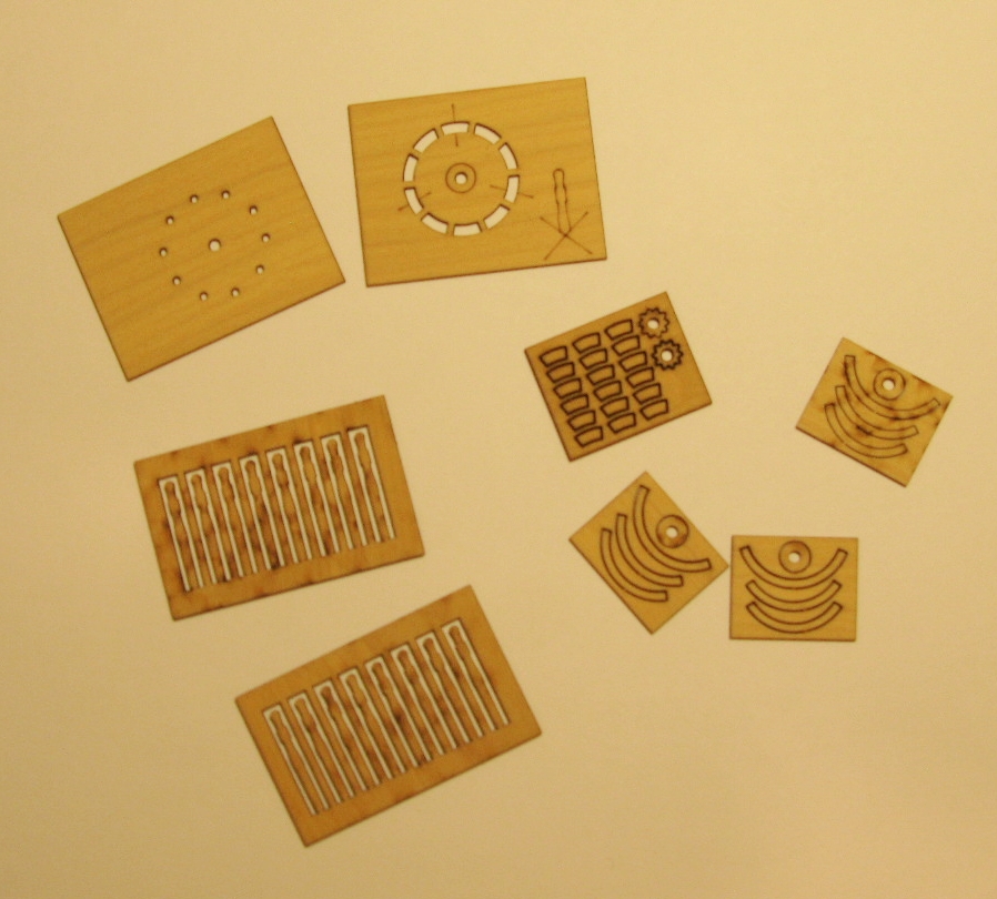
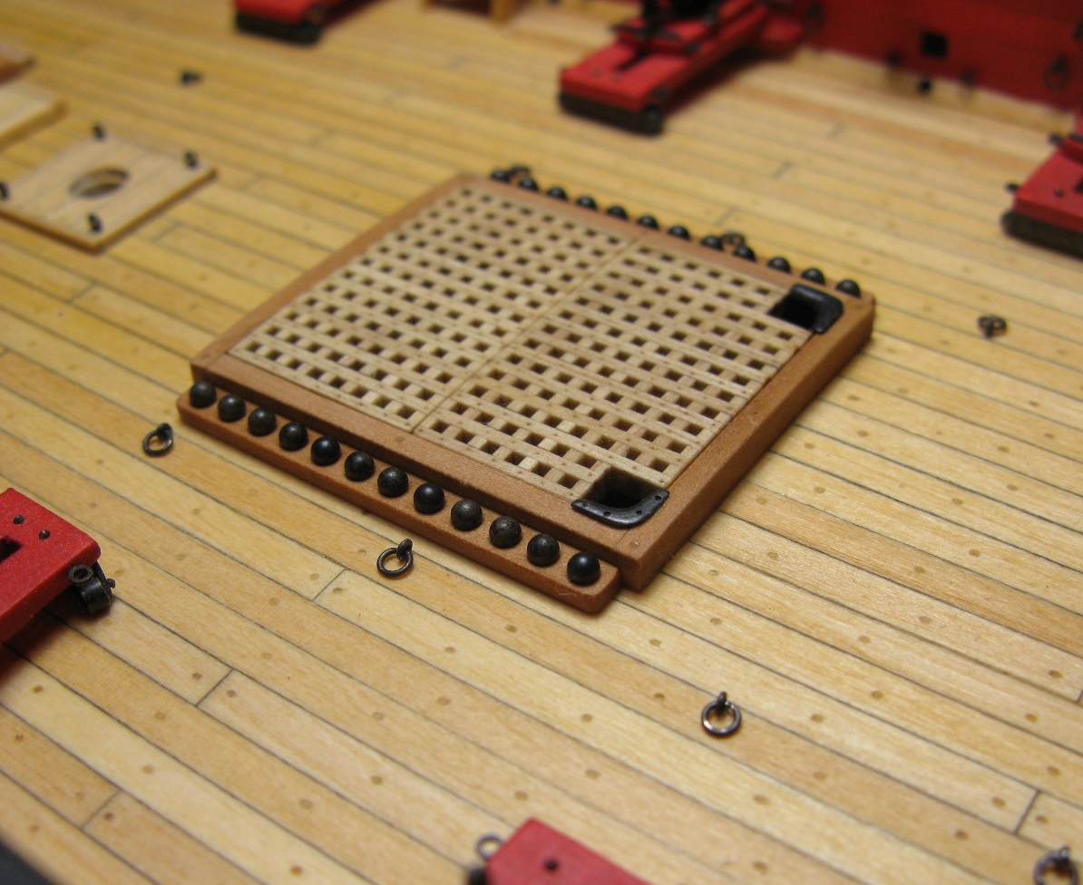
. The little time left for ship modeling was used to “clean up” my Syren model. This concerned primarily the gratings. A grating of the Victory in image 1 shows the elements which I wanted to change/include in my Syren build – which meant removing and rebuilding some “prototypes”: the “continuous” grating bars go parallel to the deck planking (my first attempt was perpendicular), there is a nailing pattern, which of course would be barely visible at the Syren scale, and the picture shows a thick smooth metal cover of the hatch edge for reinforcement of the edge and friction reduction for the heavy anker cable. I have seen this last detail the first time in Dirk’s Syren build log and really liked it. Image 2a shows the edge metal reinforcement (milled out of a thick sheet of brass) and the (re)making of the cannon ball racks (image 2b), images 3 – 5 present the self-explanatory building sequence for the ladders (made of pear wood), image 6 depicts the permanently mounted companionway with ladder, and images 7 and 8 show the final gratings.Thomas
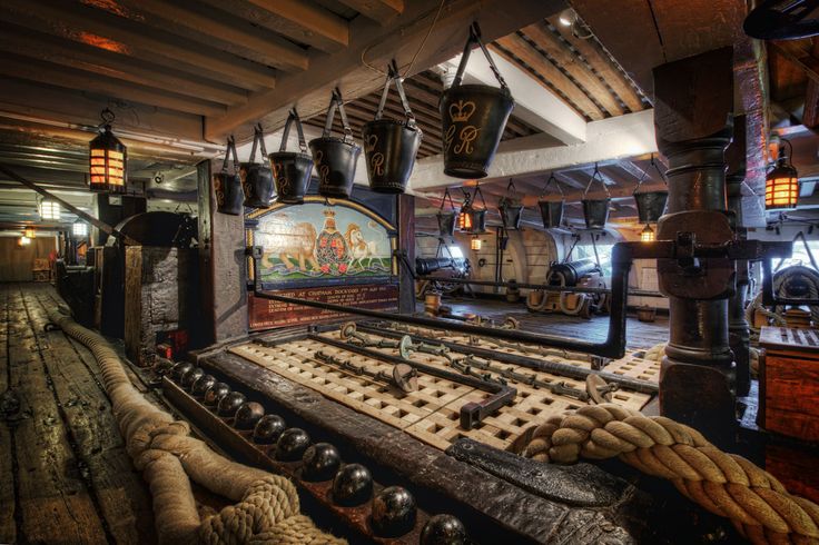
Image 1
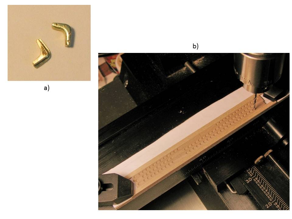
Image 2
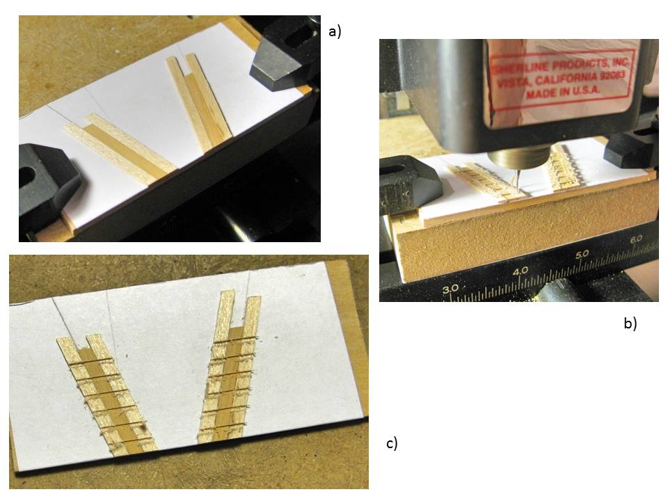
Image 3
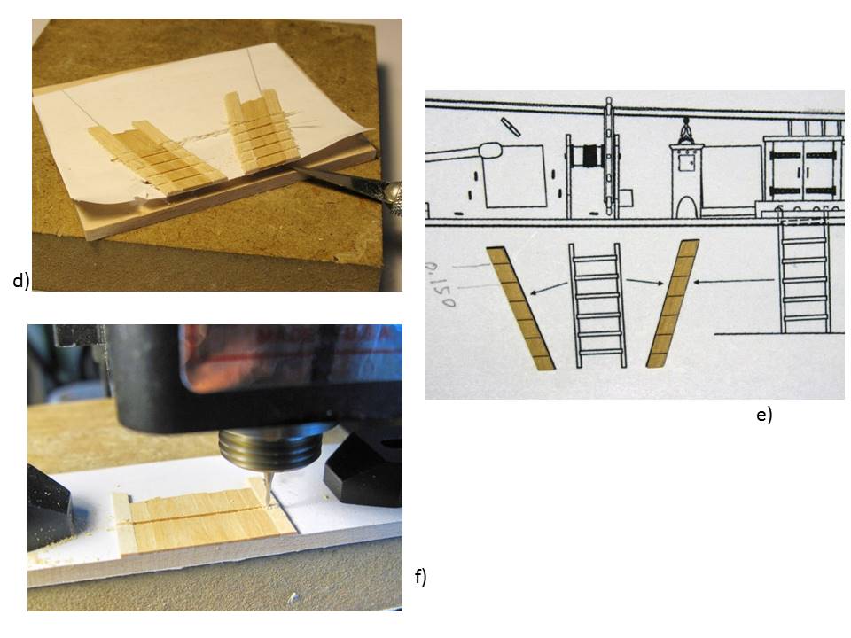
Image 4

Image 5
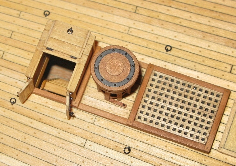
Image 6
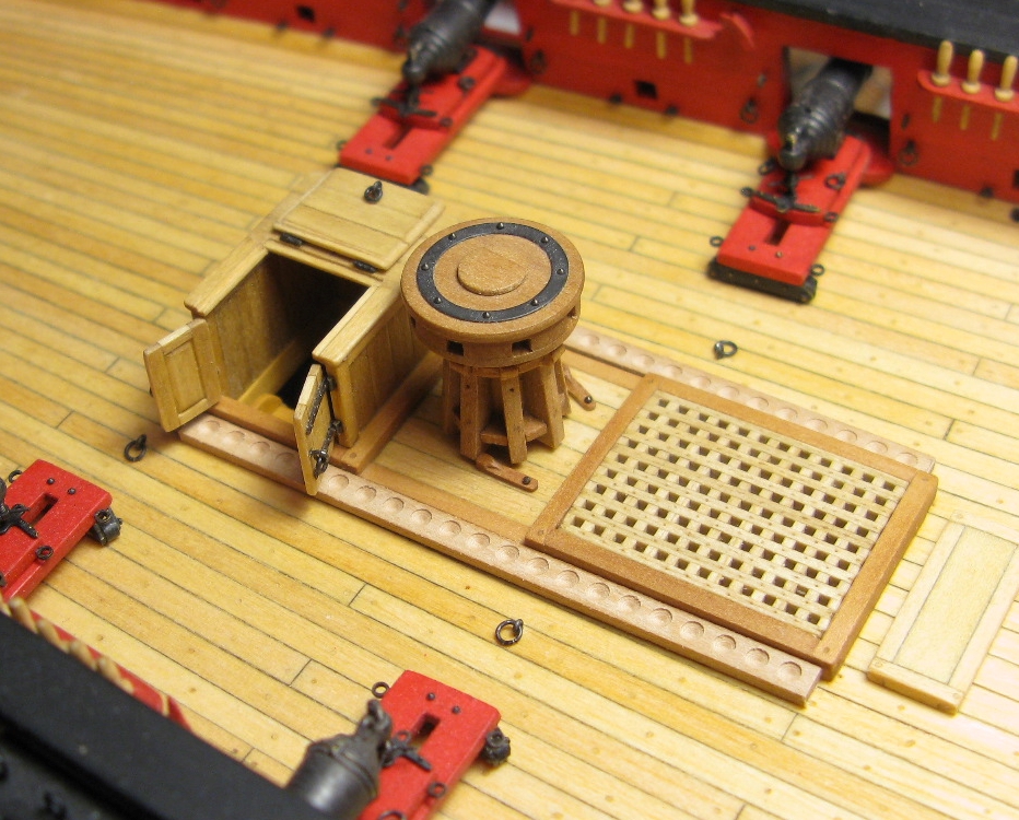
Image 7
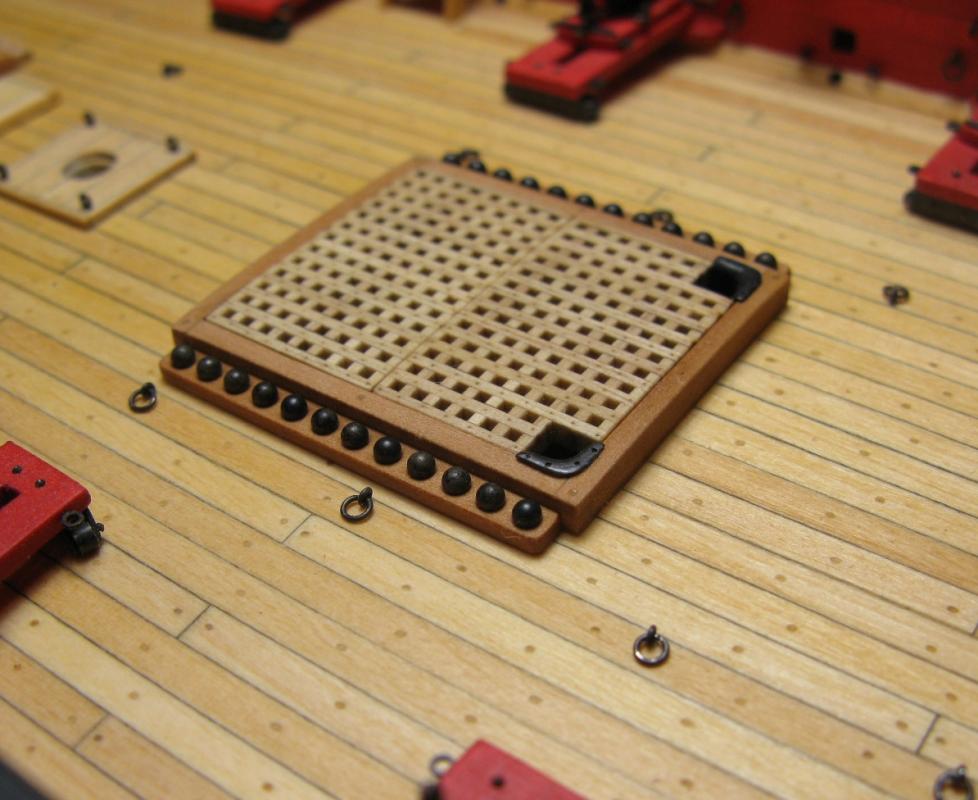
Image 8
-
Hello Jesse,
As soon as you go with slightly "more substantial" barrels than provided in the kit you run into this problem. My solution to this was exactly what Jparsley suggested: not to worry about it
. Your carronades look good the way they are. Thomas
-
-
-


Granado by rafine - FINISHED - Caldercraft - 1:64
in - Kit build logs for subjects built from 1501 - 1750
Posted
Wow, that looks absolutely fantastic!
Thomas