thibaultron
-
Posts
2,954 -
Joined
-
Last visited
Content Type
Profiles
Forums
Gallery
Events
Everything posted by thibaultron
-

Fokker Dr.I by Torbogdan - FINISHED - Model Airways
thibaultron replied to Torbogdan's topic in Non-ship/categorised builds
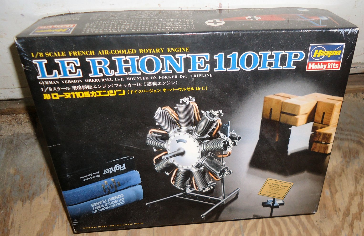
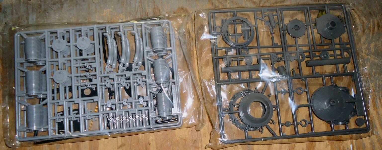
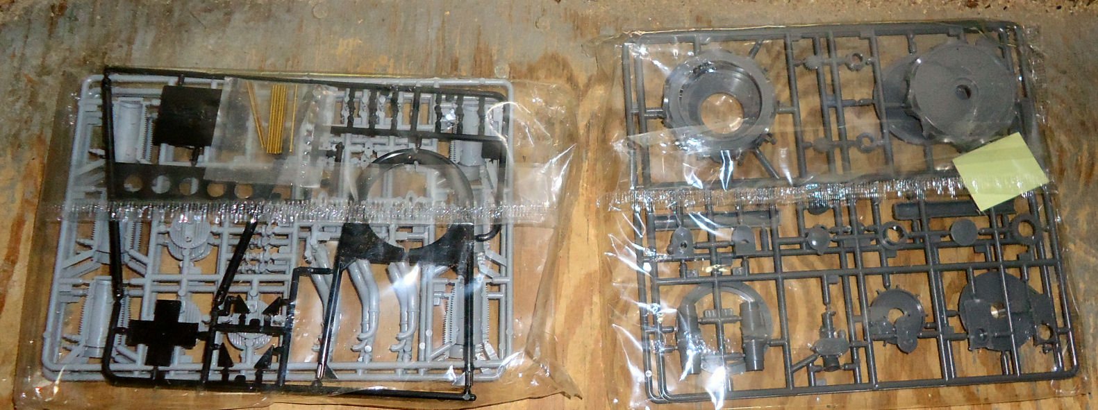
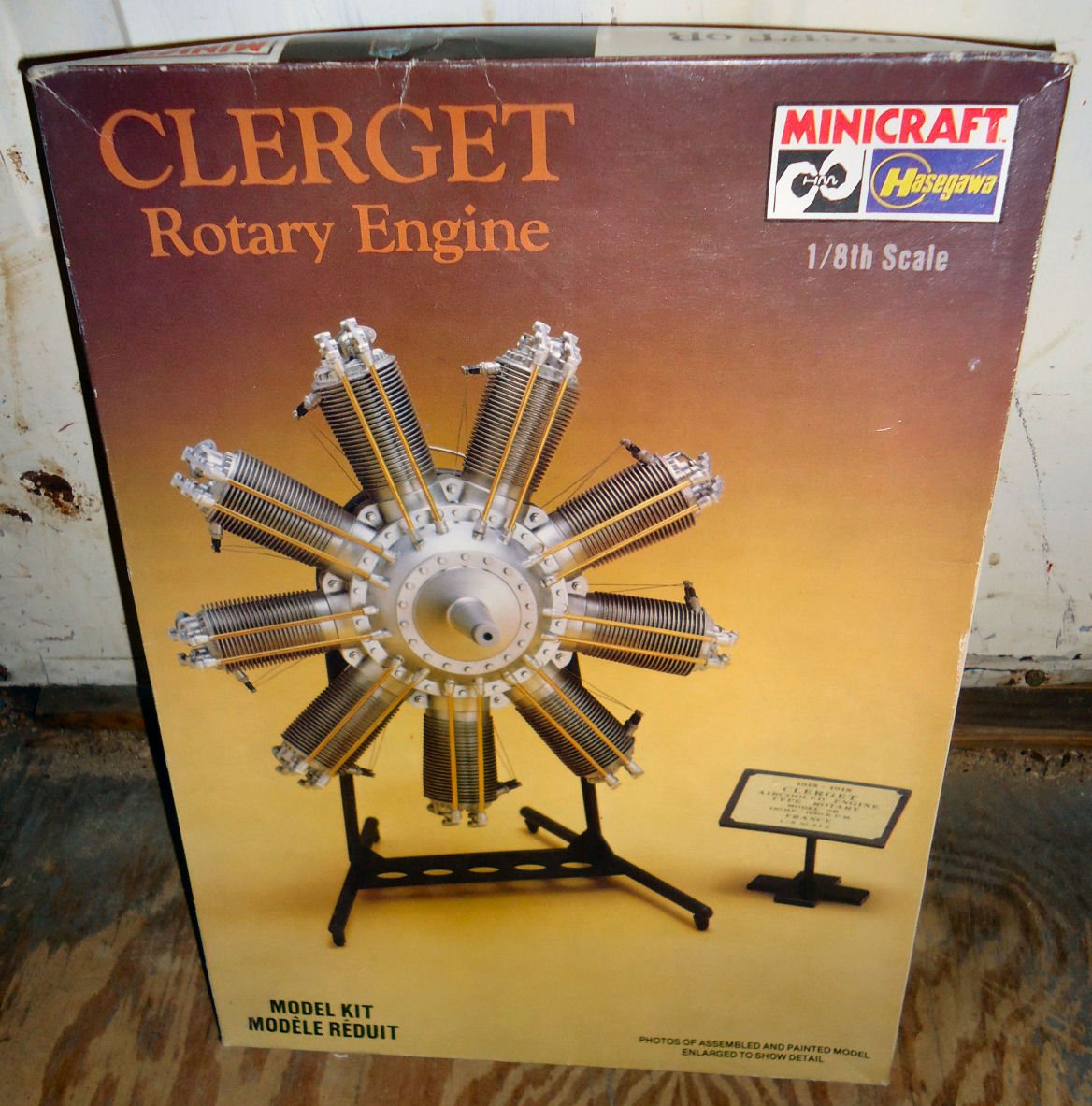
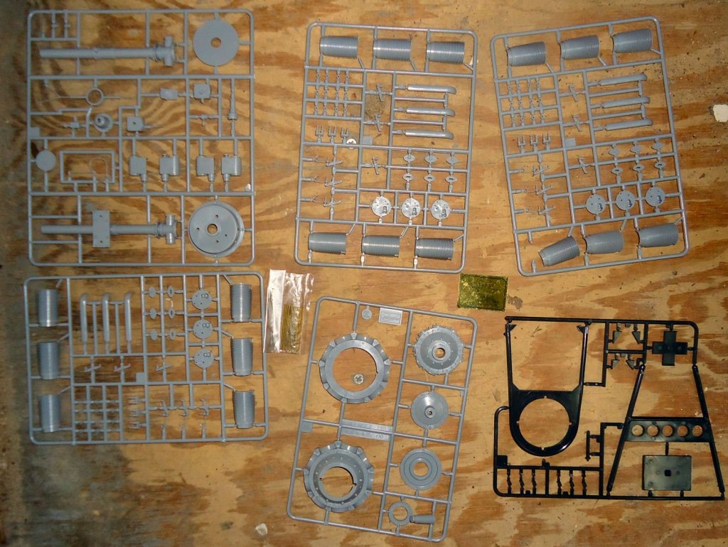
I got the two Hagasawa engine kits. The detailing looks good, at least good enough for me. The Le Rhone 110HP The Clerget 130HP A close up of the cylinder and vale rocker arm parts.


-
Vallejo and AK Weather wood paint and washes
thibaultron replied to KAT's topic in Modeling tools and Workshop Equipment
Is that the AK 259 REALISTIC WOOD EFFECTS , book? -
Fokker Dr.I by Torbogdan - FINISHED - Model Airways
thibaultron replied to Torbogdan's topic in Non-ship/categorised builds
One source I found, said that the Germans would reuse Le Rhones in the DR.1, if they captured any. Similar to your post. -
Fokker Dr.I by Torbogdan - FINISHED - Model Airways
thibaultron replied to Torbogdan's topic in Non-ship/categorised builds
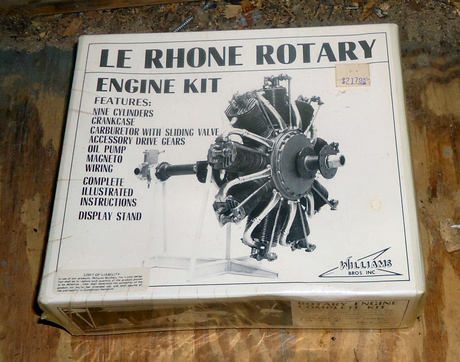
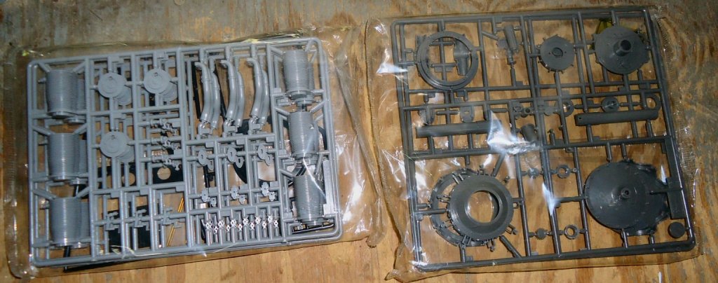
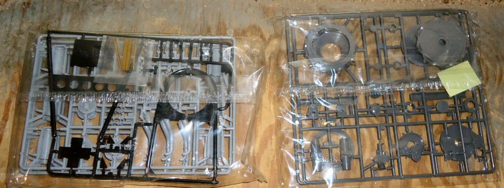
I broke down and bought one the Hagasawa Le Rhones. Should be here next week. Haven't decided whether to keep or resell the Williams Brothers 80HP model. When the 110HP arrives, I'll post some pictures of the parts. I also bought one of there Camel engines, its coming from Canada. -
Fokker Dr.I by Torbogdan - FINISHED - Model Airways
thibaultron replied to Torbogdan's topic in Non-ship/categorised builds
Enjoy your vacation! -
Fokker Dr.I by Torbogdan - FINISHED - Model Airways
thibaultron replied to Torbogdan's topic in Non-ship/categorised builds
Received the 1/6th Le Rhone 80HP engine model kit. Unfortunatly the 80HP has the valve pushrods at the front of the crankcase, and the 110HP has them at the rear! Did not notice the difference until after the kit arrived. May have to find a Hagasawa 1/8 Le Rhone kit.
-
Following this build. As a note, both sparkplug wires should run between the gear and crankcase. The way you have them running, they would be cut when the engine rotates.
-
Fokker Dr.I by Torbogdan - FINISHED - Model Airways
thibaultron replied to Torbogdan's topic in Non-ship/categorised builds
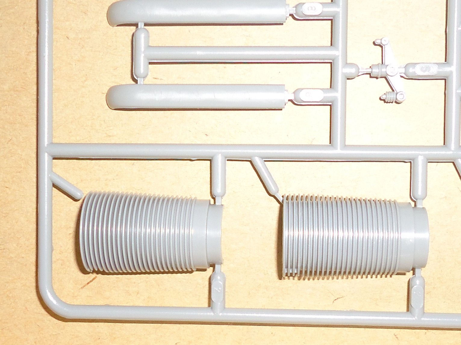
Its a nogo on 3D printing the cylinders, for the Le Rhone/UR2 engines. There are 33 fins in a actual 22CM length, and the minimum thickness for the Shapeways detail plastic is ~.5CM for a supported wall/fin, and ~1CM for an unsupported wall, AKA a fin. This is for a cylinder scaled to 1/16th. A built up PE stack might do it. You would need some combination that comes out to .0163" or .0164" thick for each fin and spacer(s) combination. It comes out to .666 real CM from top of one fin to the bottom of the "gap". -
Its in the Micro-Mark catalog.
-
Thanks from me, also, for this great build! Fantastic workmanship, and the clear explanation of the reasons for each step, it adds much to the interest of the build.
-
Maybe you could do your own PE. Here in the US, you can buy complete kits for do it yourself PE. Should be able to get them in the EU.
-
Is the pin in the gun base plastic, or part of another PE? If plastic cut it off, and drill for a smaller pin.
- 151 replies
-
- 4
-

-
- duke of york
- tamiya
- (and 2 more)
-
Frank; I forget, what period in her life are you modeling her in? As built, present, etc. Did she have power dredge winches, or hand wound?
-
I insulated mine. Well worth the cost in reduced power bills.
-
A look at the above picture also answers your shroud question. The shrouds run under the yard, not over it, as in some of your pictures of the model.
-
Fokker Dr.I by Torbogdan - FINISHED - Model Airways
thibaultron replied to Torbogdan's topic in Non-ship/categorised builds
A note: Amazon has the "Fokker Dr.I: The Aces’ Aircraft (Legends of Aviation 3D)", 2nd edition hardcover, listed as in stock for about $30 today! I just ordered one -
If you have a scanner, scan the instructions, and blow up the pictures. Great work, so far.
- 151 replies
-
- 5
-
-
- duke of york
- tamiya
- (and 2 more)
-
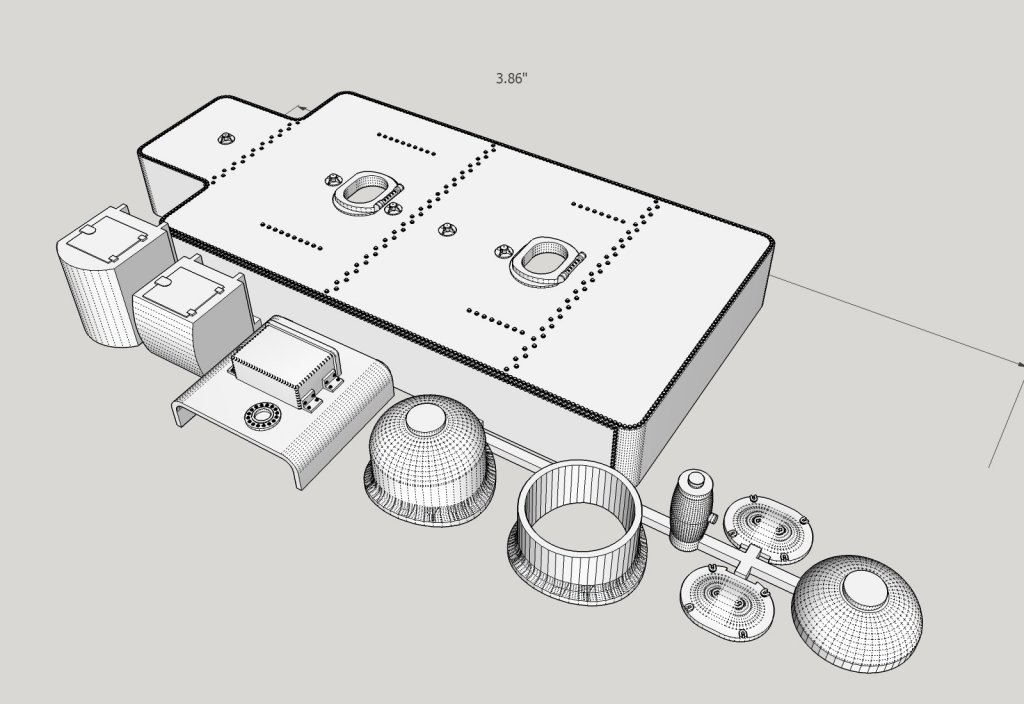
For my "stuff", I model it full size, then rescale it when I send it to the printer. I'll have to look into Blender. My tutorial is intended more to teach how to use SketchUp, rather than as a drafting lesson. I wanted to show a few tricks I'd learned along the way, also. Here's a shot of a piece of equipment I'm designing for one of my model railroad locos. It is a conversion set to modify a Bachmann 2-8-0 to a Santa Fe prototype. I could have built it long ago, but enjoy the challenge of CAding/3D printing it. If it works out I plan on making it available to others. It's an oil bunker for the tender, with a new dome for the locomotive. The second dome is for me to trial fit first, so I don't ruin the "good" one. One thing that will come out of it is a set of accurate oil fill hatches for Santa Fe locos. Most production models have incorrect ones, even the Brass locos. I have several tenders that I need to upgrade. Also the 2 tool boxes are missing on most SF loco models. I will have to stretch/shrink some of the dimensions to fit each loco, but I have the basic models to start with. It may be too complex, with all those rivets on the side, but I'm interested in seeing if it works.
-
Lazyjacks on a modern vessel, run on both sides of the sail, so the rgging would be mirrored on the other side. They are used to shorten the sail, and keep it contained while you do.
-
More tools - Luthier, jeweler, fly-tying
thibaultron replied to vossiewulf's topic in Modeling tools and Workshop Equipment
Ebay has the Horico dental sanding strips -
In one of the other threads, someone mounted his hull on an angled base, and drilled with a drill press. That is the method I'll use in the future.
-
3D-printing for modellers?
thibaultron replied to Jean-Pierre's topic in Modeling tools and Workshop Equipment
Just shapeways, for now. A 3D printer is on the list, but I need to finish my shop renovation first. -
3D-printing for modellers?
thibaultron replied to Jean-Pierre's topic in Modeling tools and Workshop Equipment
I use SketchUp as my main 3D software, with DesignCAD as my drafting software. I have a thread on going from 2D to 3D that I did last year, in the forum, see my signiture below. What you can print, depends on the size of the parts. I was able to 3D print hand powered oyster dredge winches, about 3 X 2 foot, in 1/64th scale, but not the pipe dredge frames. For Shapeways the minimum floor/wall thickness, in their Frosted Detail plastic is .3mm, with wire minimum about 3X that thick. Long thin parts have a tendency to warp. I've also printed HO scale steam locomotive tender frames, in one of their cheaper plastics, and oil hatches for the tender tank top. -
I have both his rigging books, great resource!