HOLIDAY DONATION DRIVE - SUPPORT MSW - DO YOUR PART TO KEEP THIS GREAT FORUM GOING! (Only 20 donations so far - C'mon guys!)
×

FrankWouts
-
Posts
535 -
Joined
-
Last visited
Content Type
Profiles
Forums
Gallery
Events
Everything posted by FrankWouts
-
 Welcome Kurt, You bring a lot of good wood working experience to this group and I like your style of writing. It will be great reading your log and following your build! Frank.
 -
Hi Hans, Simply very, very beautiful work on 'the ship' of us Dutchies. I hope the negative feeling about that person's negative comments disappears when I tell you it really takes my breath away to see your beautiful build and that I'm getting anxious to start my own with Blom's drawings after HMS Winchelsea. Only thing is Chuck plans a POF project also after the Winchelsea project. So there will have to be made some choices... Frank.
-
Beautiful work and great progress! don't understand how you can move so fast...
-
Great progress and looking very smart Ben! Frank.
- 399 replies
-
- 1
-

-
- winchelsea
- Syren Ship Model Company
- (and 1 more)
-
You're welcome Glenn, that's what's this group build is for, to keep each other on the right track. Luckily no redo needed, like I had to do with my lower counter planking, which was quite exciting when I chiseled away the lower three counter planks in small splinters...
- 840 replies
-
- 1
-
-
- winchelsea
- Syren Ship Model Company
- (and 1 more)
-
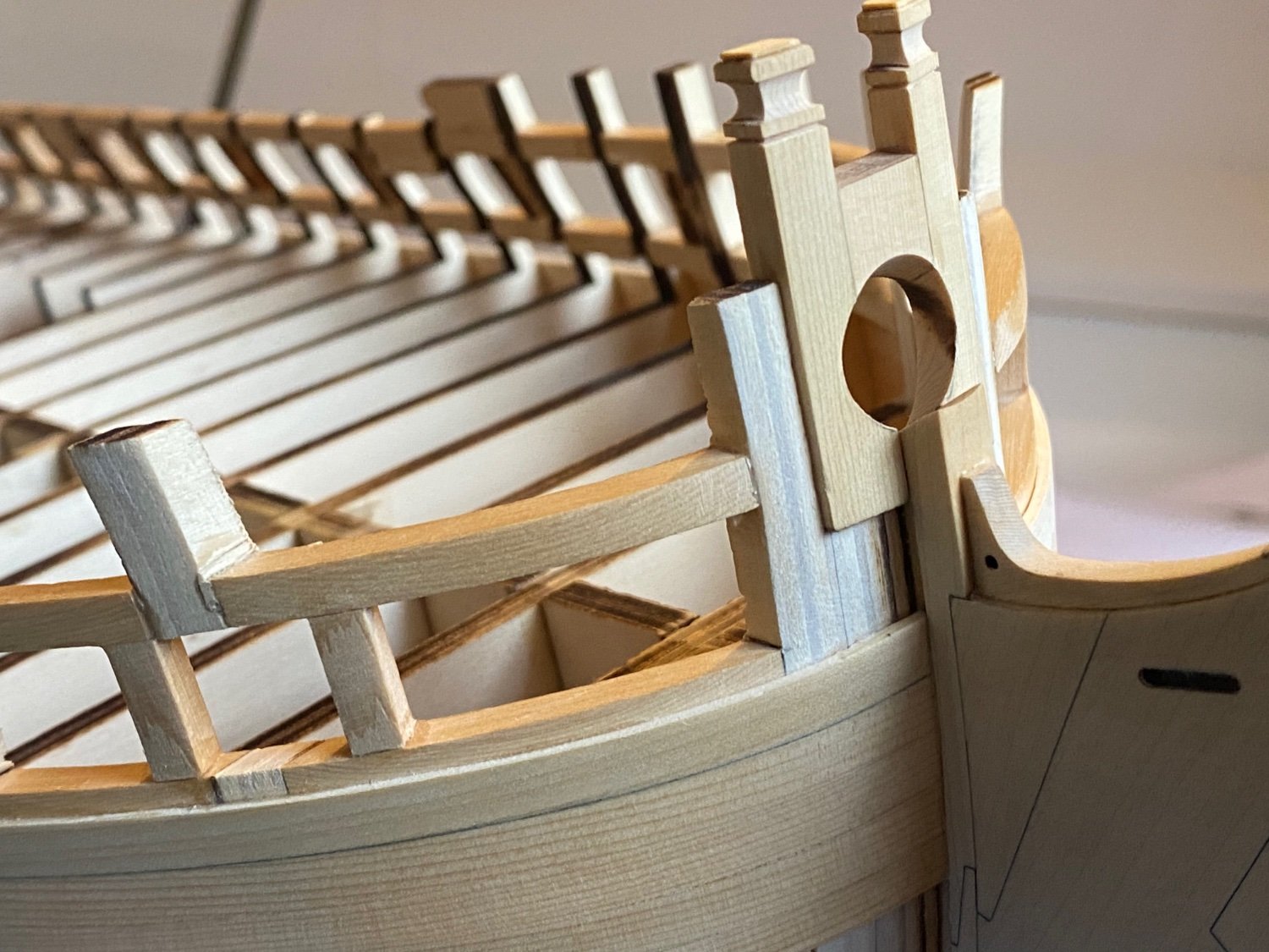
If that’s enough to make and sand the bow planks flush with the skewed bollard timbers, I guess you’ll be allright. Mine are skewed just a little more as maybe I oversanded the bow filler pieces a little. No real rights or wrongs I think, as long as you are satisifed with your work yourself!
- 840 replies
-
- 2
-
-
- winchelsea
- Syren Ship Model Company
- (and 1 more)
-
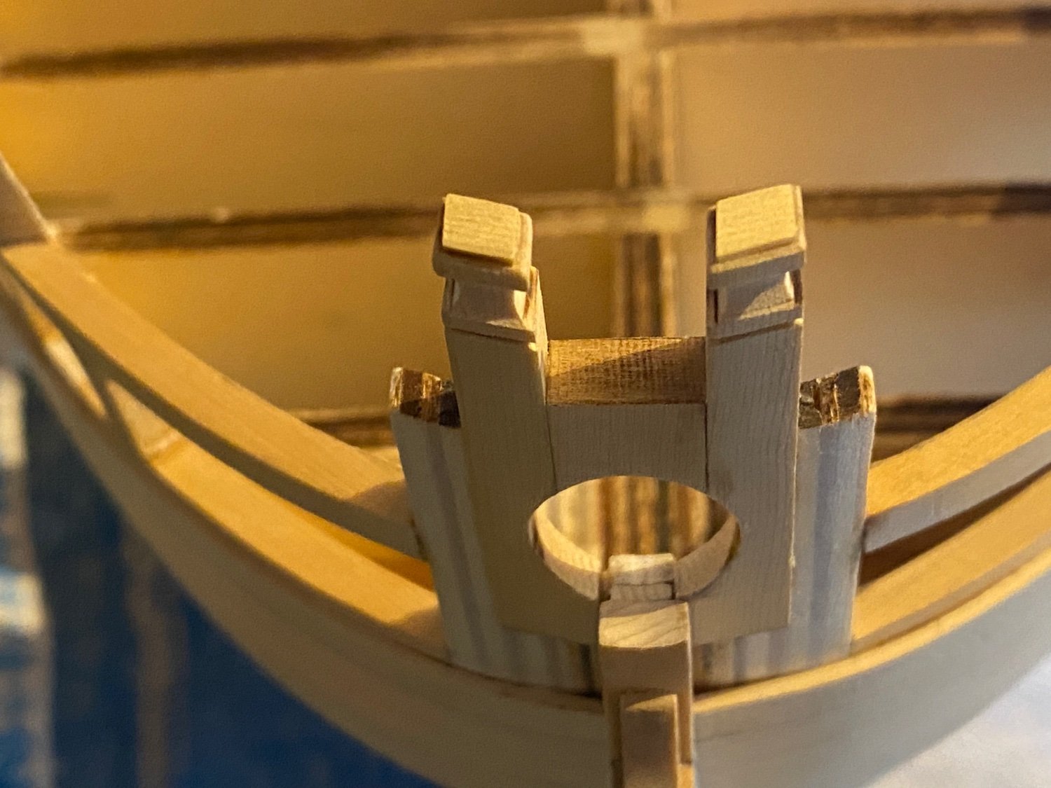
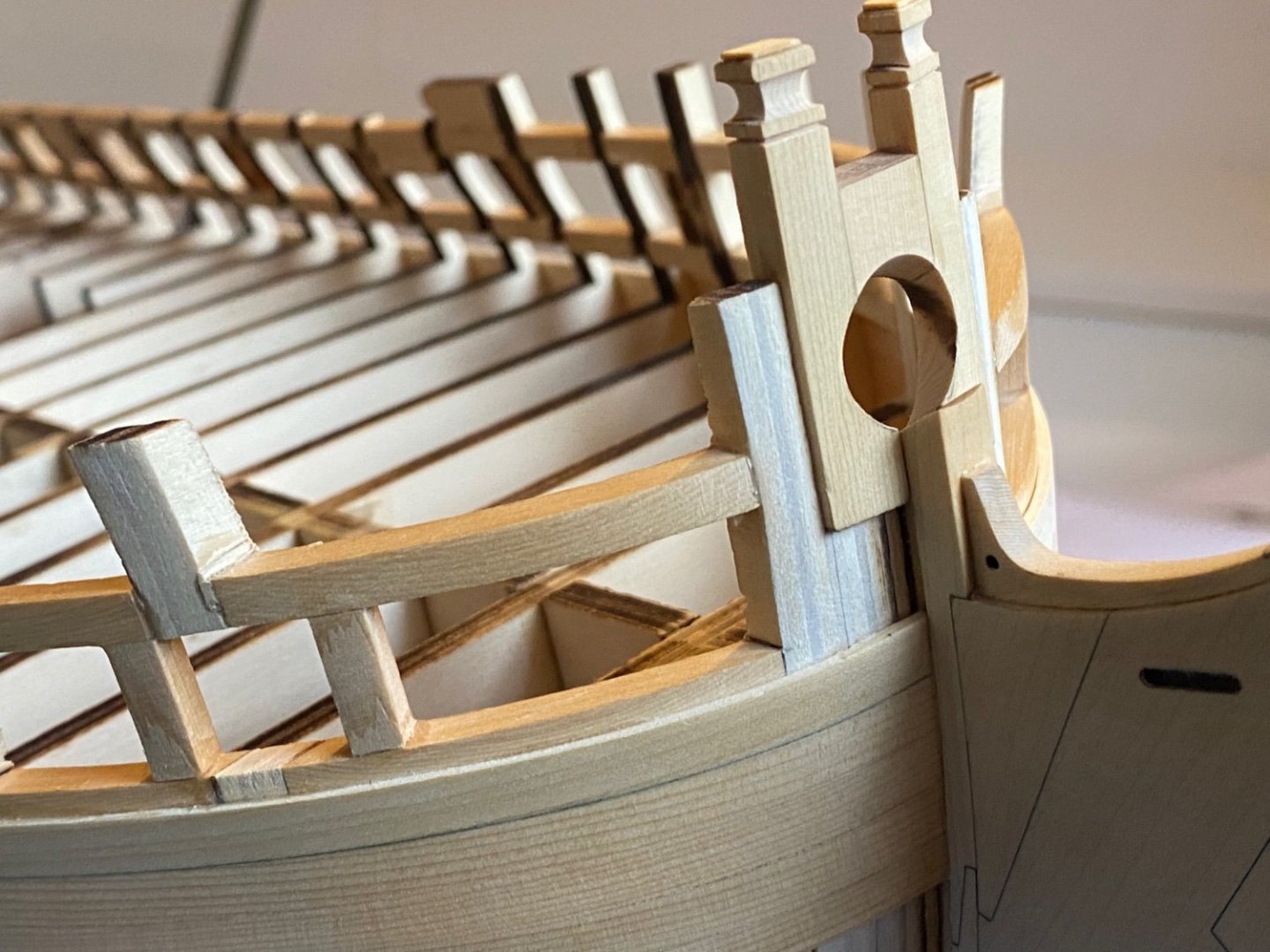
Hi Glenn, very nicely done, but shouldn't the bollards be formed in an angle, following the curve of the bow? See the plans what I mean. Also I think the bowsprit hole should be filed and sanded in an angle, given by the angled piece of wood that sits right in front of it, and Chucks instructions ofcourse. This way your bowsprit probably will not kill your mandolin player sitting on the bow later on? Mine is not perfectly round yet, because I’m thinking of maybe fully rig the model and I want to be sure the diameter is not too big at forehand.


- 840 replies
-
- 8
-
-
- winchelsea
- Syren Ship Model Company
- (and 1 more)
-
Very beautifully done and that in such a fast pace!
-
Clear, thanks Mike!
-
Thanks Jim, I may do it that way. But this is only the first layer, according to Chuck's description I believe I first have to plank above the wales and then add the second planking of the wales and paint it? I'll read it again anyway...
-
Thanks Matt and Scrubby and everyone for the likes! I’m quite satisfied myself as well thusfar. I hope I can maintain this level. Frank.
-
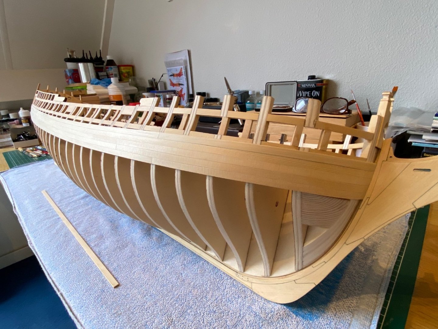
*************** Chapter 2 *************** Added two times five rows of 7/32 planking. Practiced with my 3B pencil under the upper row. Waiting for my ochre red paint to arrive from the UK. Frank.
-
Thanks for sharing the rest of your inspirational build with us again, I was afraid you had given up.. Very smart 3D printer you must have there. Wow, what a detail on that locomotive!
- 399 replies
-
- 3
-
-

-
- cutty sark
- revell
- (and 2 more)
-
Happy New Year Matt! I also have a habbit of frustration with small and very little parts, because they always end up in my carpet monster with me searching for them on my knees…
-
You’re making great steps forward Glenn. Very nice curvature in that stern framing! I almost made a mistake there, but yours looks fantastic!
- 840 replies
-
- 2
-
-
- winchelsea
- Syren Ship Model Company
- (and 1 more)
-
Welcome Dusan! You’ve made a great start! Frank.
-
Le Soleil Royal by Nek0 - 1/72 - Marc Yeu
FrankWouts replied to Nek0's topic in - Build logs for subjects built 1501 - 1750
Happy New Year Marc! Any updates on your beautiful Soleil Royal project?- 208 replies
-
- 4
-
-
- le soleil royal
- 104 guns
- (and 2 more)
-
Perhaps indeed it's a matter of taste, but also be considered should be that sometimes a huge amount of muscle force was used to lower or raise the guns to aim...so little more robust would be my taste as well.
- 642 replies
-
- 1
-
-
- winchelsea
- Syren Ship Model Company
- (and 1 more)
-
Great good looking job on those Matt!
-
Simply beautiful work! Frank.
-
I think everything will be fine now. Frank

-
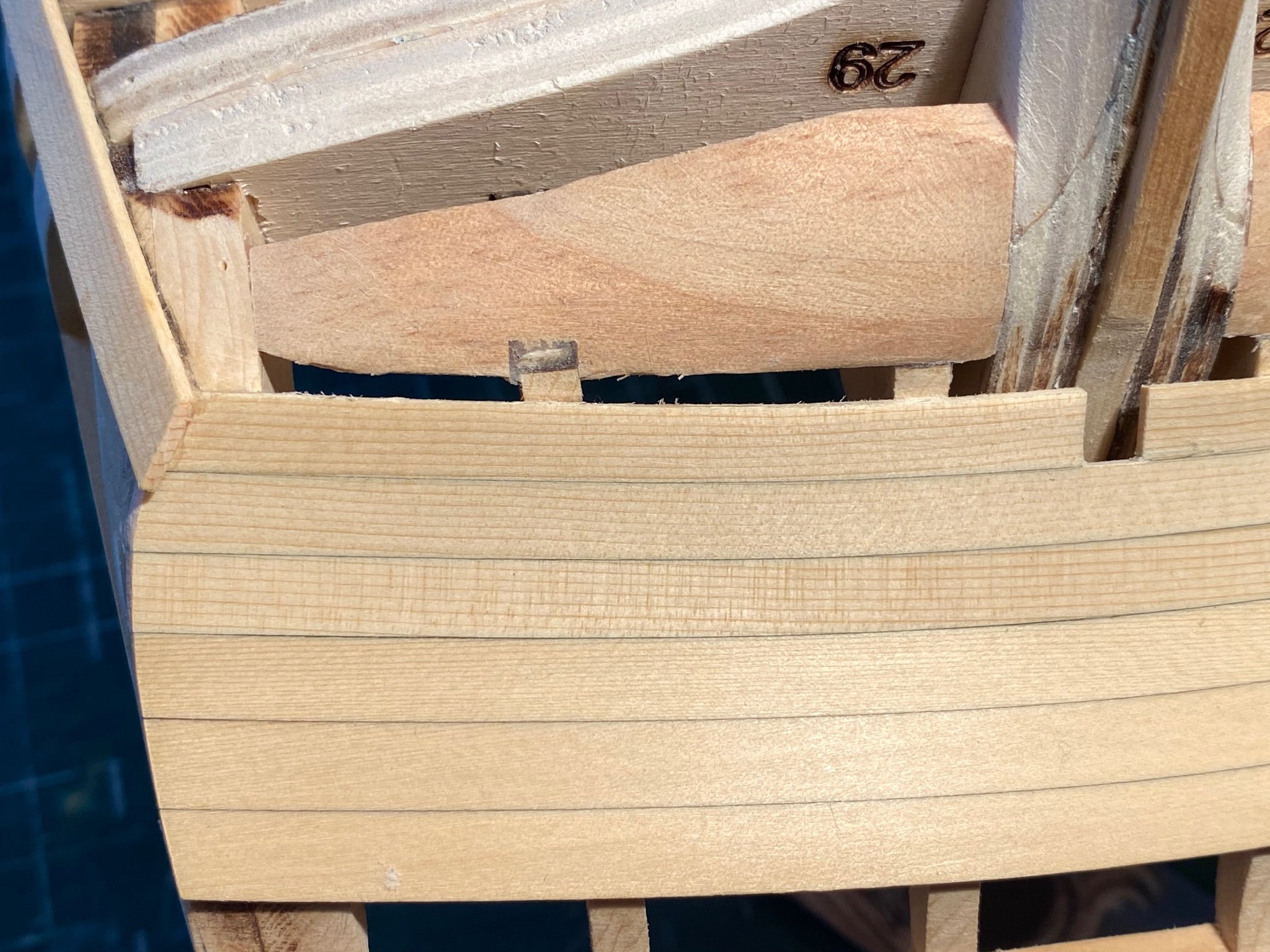
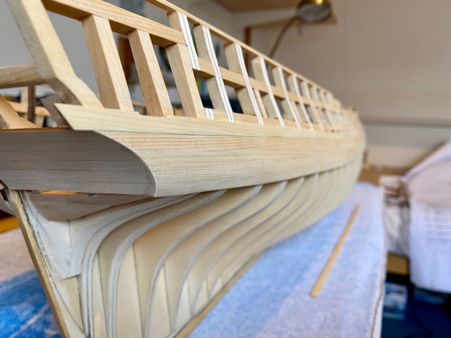
I took "winchaptertwo.pdf" as a reference to measure the hight of the precut counter planks and planked on till I had the same width again, Also I had still some reference line from my chisel / glue of where the edge of the smaller, lowest counter plank had been before I removed it. Frank.
-
Thanks Mike, I did it this way because filling the oversanding area first, would leave me with the same problem of how much I would have to file and sand it down again. First shaping the counter to the correct form will give me a reference for how much filling up and file/sand down again the area behind the counter. Ofcourse I could have done it the way you describe and file / sand both the counter and filler together... Frank
-
I’m in for a POF Speedwell as group project as well! I estimate in 2 years from now with Winnie completed. Merry Christmas everyone!

- 1,784 replies
-
- 1
-
-
- winchelsea
- Syren Ship Model Company
- (and 1 more)