HOLIDAY DONATION DRIVE - SUPPORT MSW - DO YOUR PART TO KEEP THIS GREAT FORUM GOING!
×


Martin W
-
Posts
1,412 -
Joined
-
Last visited
Content Type
Profiles
Forums
Gallery
Events
Everything posted by Martin W
-
 Thanks for checking in, guys, and especially for the advice. Spyglass, you make a good point. I hadn't thought of checking how the extensions affect the angle that will happen. I'll definitely check that, and maybe with a tracing as I did on the bow. BE -- Thanks for the reminder about opening up those extensions. I've studied the chapters of your log -- the ones that might be called, "Pegasus: The Early Years" -- and do recall that you cut out chunks of the extensions to turn them into open frames. Your photos there show them to be plywood, so I take it that you just used the kit's frames and cut out the insides? -- And it was seeing the mishap that occurred a while later on, that convinced me not to put them on at all just yet. I might also mention that I got the sheet of plans (the frames) of The Fly from NMM -- oh boy! not only are they very informative, but they're a joy to look at. Well worth the price, I'd say. And now I see little reason not to get the deck plan. Cheers, Martin
 -
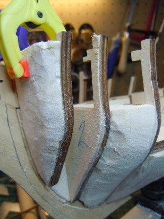
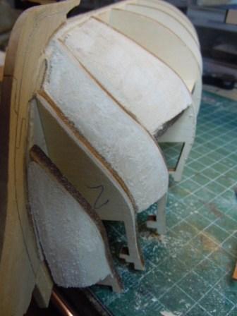
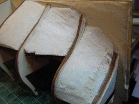
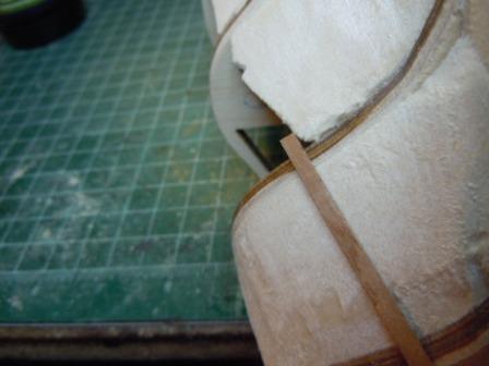
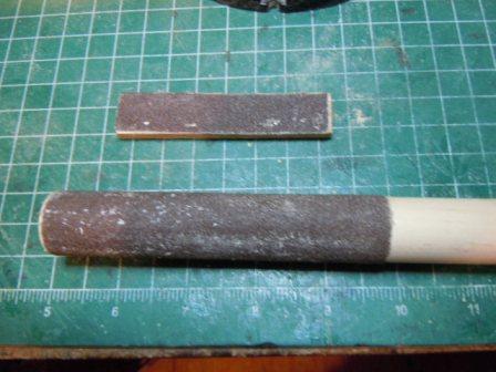
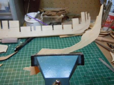
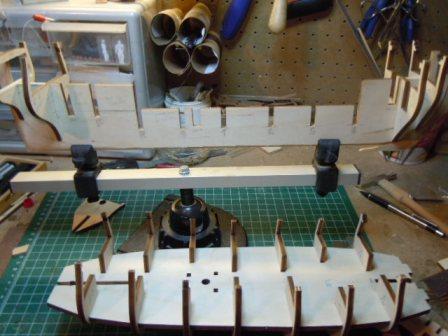
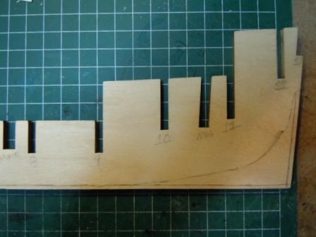
Greetings -- It's been a few weeks since my last posting, but only because I've spent my time in the boatyard (and the backyard) instead of my computer room. After setting all the other bulkheads in place, I trial-fitted the stern extensions, just to get a sense of their purpose, and how they'll look: I didn't attach them, because they looked pretty precarious. I actually haven't glued #13 on yet either, just because i want to get as much work done as possible before setting it in permanently. Then began the task of putting in filler blocks. These I cut with the scroll saw, more or less to shape (mostly less), and glued in: These are the fillers at the bow. You can see they're all still rough hewn. The space between bulkheads 1 & 2 is so narrow that I don't see the need for filler blocks there. And here's the bow with the blocks sanded down. In order to determine the shape of the bow, I traced the outline from the kit's deck plan, and then drew the outline onto the balsa and bulkhead 1. You can see the center point that I marked on the tracing, and you can see the bit of the first bulkhead (port) that will need filing down. And here's the bow after filing: Now to the back. The aft bulkheads. The process of fairing is underway here. I'm not sure how to judge the amount to file off the bulkheads. I've mostly just used a piece of planking to see if it lies flat -- like this: And these are the sanding blocks I made up to create as much dust as possible: I was advised to put in some blocks to shore up the bulkheads amidships, which I did -- I thought I had a photo of them, but guess not. Anyway, on the Rattlesnake I installed balsa filler blocks between all the bulkheads, making for a solid hull to lay the planks on. That had the benefit of allowing me to forgo a first planking. For this build, however, I'll be doing the double work. Now on to the deck. Cheers, Martin


- 467 replies
-
- 1
-

-
- fly
- victory models
- (and 1 more)
-
Hi Jay -- This thread has been very interesting for me. I bought the Micro Mill from Micro Mark last summer and am just now trying to figure out how to run the dang thing. I went to the MM site, and this mill is no longer listed, so I guess it's been discontinued as being too small. It was what I could afford, though, and since I don't plan on milling metal, it made sense. The main difficulty for me is that there is no such thing as a "User's Manual" that might show how to attach the vise to the table. My vise looks just about like yours, though I can't find the pieces in what I got that would seem to hold it down. I'm sure I'll be coming back to this thread, to compare your photos with what I see on my machine. Cheers, Martin
-
Hi Joe -- Nice build. Your color scheme, along with the copper bottom, makes for a very handsome and neat appearance. This was my first build, quite a stretch for me, but I found out how fun this hobby could be. I wish I could say my build looked as good as yours. Keep at it. Martin
-
Hi Brian -- That's a nice build you've got going there. The care you've taken on fairing the bulkheads and shaping the filler blocks will pay off as your planking progresses enough for you to see the pretty lines. I like the detail you're adding to the bulkhead doors, too. Very nice. In one of your photos, Ben Langkford's name was visible on the plans. So even though your kit might be old, the plans are reliable and have enough detail that you can get lots from them. I built the Mamoli kit, and ended up tossing about 3 of the bulkheads because they were so far off. keep at it. Martin
-
Och! You got me on that one, Peter. Even the Ancient Mariner's ship was rigged by some sort of "hands". Cheers, Martin
-
Nice work, Peter. The furled sail is a great touch, and it's really interested to see the rigging go up with sails rather than by itself. Cheers, Martin
-
That's a nice, systematic job of planking. It looks neat and orderly, just as it should. Cheers, Martin
-
I like your technique of laminating pieces together for the ribs. That would certainly seem to solve the problem of basswood crimping. Well done, Martin
-
Beautiful work, Toni. All I can say is wow! make that WOW! Anyone with a dog for a shipmate is ok in my book. Cheers, Martin
-
That framing is something to behold. It would be hard, and even a shame, to plank over it. Cheers, Martin
-
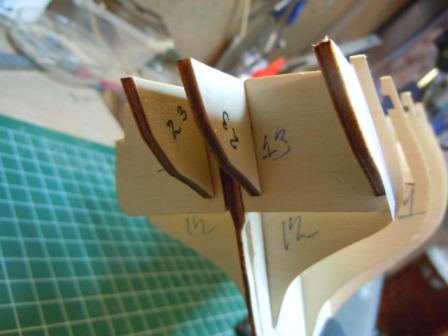
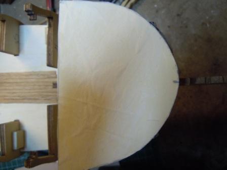
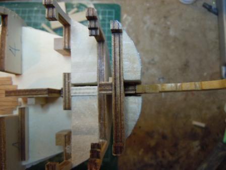
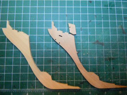
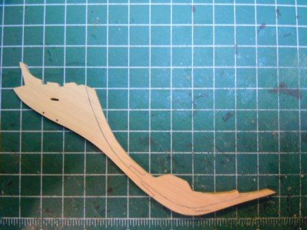
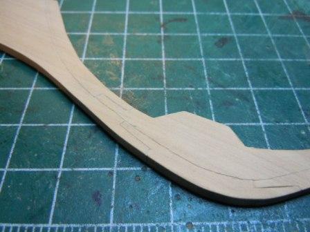
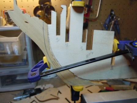
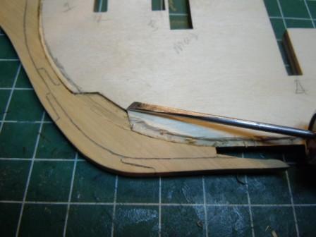
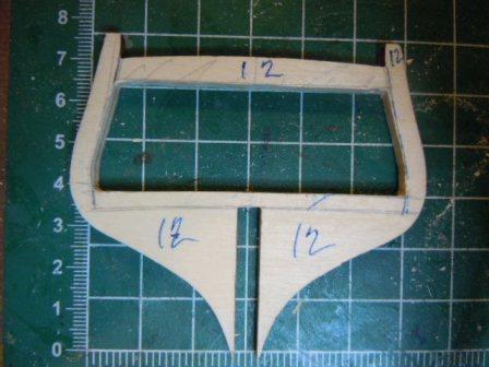
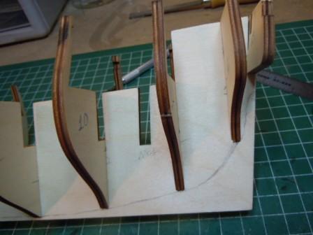
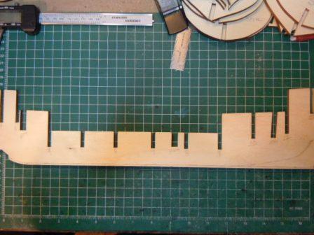
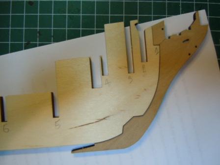
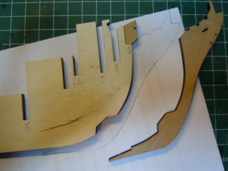
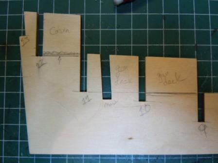
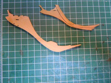
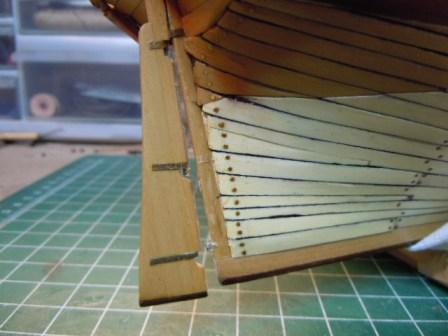
Greetings -- There's been a bit of progress, even though most of my free time has been given over to paving stones. As I mentioned, I wanted to replace the kit-supplied walnut plywood stem with a boxwood version. In my usual fashion, I vacillated between cutting the individual pieces that would be glued together, cutting out a single piece with the jointing simulated with gouging, or not replacing the stem at all. Since one reason I enjoy building these ships is that I want to develop some skills in small-scale wood working, I decided I would take the route that involved some cutting and so on, but not too much. After tracing the original stem onto a piece of white paper that I rubber-cemented onto some boxwood stock, I cut out the new stem on the scroll saw (I used a 28 tpi blade). Here’s the rough cut new piece in the vise being preddied up with a small file. The new stem next to the kit-supplied version for comparison. Hmm, maybe a touch more filing along the inner line there? Here it is smoothed out, with the jointing lines drawn in (if you squint, you’ll see ‘em). I’ve also drilled the holes. And. . . I cut along the pencilled lines for the simulated jointing. The new stem attached to the hull: Here you can see that I cut a rabbet to follow that of the hull: I free-handed a line in pencil, cut it lightly with an exacto, then used a small ( 5/32") skew to cut the actual rabbet. – You can just see the skew off to the right. That bit that broke off is still missing off, primarily because I kept forgetting that it also needed hole drilled into it, so it’ll just have to wait till this evening (it also needs just a skosh or two of fine tuning). And now to the back. I spent a few days looking at the early pages of build logs for other Flys and Pegasuses to get a sense of what to cut and how much. In the end, it’s not at all difficult – at least so far. Here’s bulkhead #12, which as supplied in the kit would cut across the middle of the Cabin. I traced the inner lines of #11, and then measure the bottom line from where the deck will theoretically go. I might also mention that I cut the thick plywood on the scroll saw with a 15tpi blade. And now, here’s the false deck, with the bulkheads glued in place, ready to be fitted onto the keel. This step took several trial runs, since the fits are all very snug, and required at least some filing (usually very little). Once I got everything set on and squared, I committed myself to glue. Unlike the previous 2 builds I’ve done, the design on the Amati Fly has the false deck holding the bulkheads into place. There seems to be little chance of the individual bulkheads slipping out of square, so the actual glue-up goes much faster. Next, I guess it will be time to cut some balsa fillers. Cheers, Martin
- 467 replies
-
- 5
-
-
- fly
- victory models
- (and 1 more)
-
Nicely done, Jon. This clearly required some patience, but you seem to have learned plenty from working it all out. Cheers, Martin
-
Fantastic and an inspiration to us all! Cheers, Martin
-
Well done, Jon. It's always frustrating when something doesn't work and it seems that it should. But when you figure out a way to get the job done, then woohoo! it's victory! Cheers, Martin
-
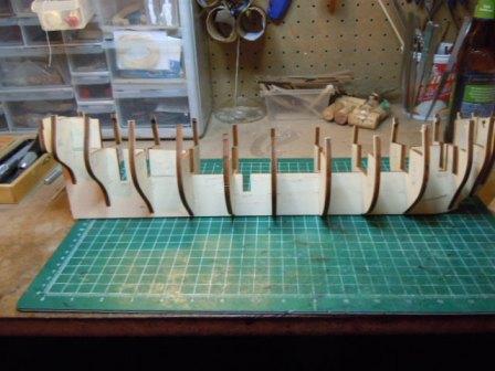
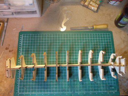
Hi Folks -- Just a quick update in between other tasks (as in the ones I'm supposedly being paid to perform). First off, here's the frames dry fitted to the keel: And the same from above: The frames all required a bit of sanding just to get onto the keel, but once on they seemed to fit naturally square (though I might change my mind about that when I actually give it more than an eyeball check). They also seem symmetrical, which was far from the case with my previous 2 builds With the frames in place, I was able to draw the Bearding Line: And my thanks to Blue Ensign for pointing out in his build that the kit's instructions don't say, "Draw the bearding line." There's every chance for me to think I simply would have forgotten it if I hadn't read that detail. Here are the Bearding Line & Rabbet drawn and awaiting my chisel: And then, here they are cut, sanded, and done: Ok, as with just about every photo I've ever seen of the Bearding & Rabbet, this one doesn't show diddly, due to the lack of real contrast between cut and uncut wood. But I assure you they're there. I might also mention that one slight lack in the otherwise good drawings that came with the kit is a sheet of plans showing the lines and frames of the hull, and showing the layout of the decks. Following the advice of David Antscherl in FFM 1, I spent a bit of time (way too much, really) on the National Maritime Museum website yesterday tracking down the plans of The Fly. (It took me too long because I kept typing the catalogue number incorrectly.) The plans in their collection are pretty revealing, and could be enormously helpful in any bashing, even slight bashing, such as opening up the cabin: a notable detail here is that forward from the Great Cabin are the Coach and State Room. So to open the Captain's cabin should entail opening another space divided asymmetrically. But, and this is a big but, they cost over twenty quid a sheet, plus another fourteen each for shipping. There are three separate sheets -- one of the lines and two of decks. Just to buy two would have run poor me over $120. It is possible to study the plans online for no charge, however, so I did plenty of that. And then by the end of the day, my appetite was whetted enough that I bought one sheet. Thus I have proved myself to be very frugal. Still, I would encourage any builder of a Swan Class ship model to check out what the NMM has. Cheers, Martin
- 467 replies
-
- 3
-
-
- fly
- victory models
- (and 1 more)
-
Scott -- Follow this link, it should get you to a posting by Chuck Passaro on Bill Short's log of Sovereign of the Seas; and the posting has a link to Bill's own website. http://modelshipworld.com/index.php?/topic/468-thank-you-bill-short-for-sponsoring-model-ship-world/?hl=%2Bbill+%2Bshort If that doesn't work, you can always email Bill at Modelshipwright@sympatico.ca. Cheers, Martin
- 264 replies
-
- 1
-
-
- rattlesnake
- model shipways
- (and 1 more)
-
That's a great digression, BE. I've never been aboard the Victory, but have read about the canvas on the floor. I guess if I really wanted to approach accuracy, I would paint squares on a piece of canvas and put that in the cabin. Even on the decidedly Puritanical American ships, though, there were plenty of delightful decorative touches. That's one of the many things that make eighteenth-century ships fascinating, I think -- they're not quite as far gone with the curlicues as the 17th-century vessels, but still lovely to look at. Thanks for checking in, Scott. Cheers, Martin
-
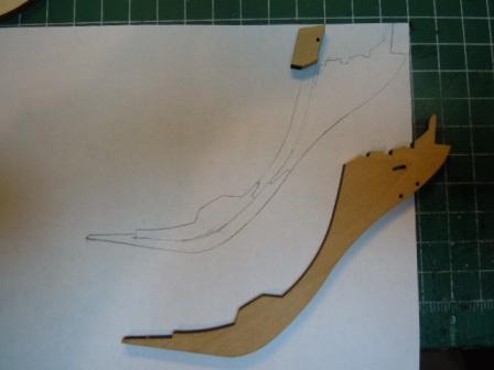
Hi Alistair & BE -- Thanks for checking in, and for the advice; comments from experienced builders (even those with no more experience than I have!) are always welcome. I think scoring could work, would take a lot less time, and would look good. The only remaining question is how the walnut would look against boxwood planking; if I kept the walnut stem, I would have to paint it, eh? You're both absolutely right about the FFM books -- I have all 4 and consulted them through my Rattlesnake build. In fact, I'm afraid I have something of a compulsion about getting my hands on any book I can that might help even a little. I also got Alan Yedlinsky's book on the Euryalis (not sure of the spelling there -- I tried it 3 different ways and every time it looked off), and it's been a help as well; and Alan himself helped out in making the jig for the steps. So I'm still thinking of at least trying out a new stem. I'm in no rush, and I can always use the practice on the scroll saw. Here's what I've done so far (I'm skipping the parts where I sat and stared, saying "hmmm, hmmm" over and over). Here's the stem laid against the hull, where it fits nicely. On the paper underneath, I made a tracing of the stem: Hello, what's that? Ahh, as I studied the diagram I noticed that there was a bit off the top. Oof! -- If I do keep the walnut, I'm sure I could glue this piece on pretty securely, so it's no big deal. Here is how I worked out the joints. I'm not sure how you other guys scored yours, I'll have to go back and check for comparison. But this looks kinda close, based on Greg Herbert's build in FFM II. Next -- it's good to hear, BE, that cutting out the space for the cabin isn't that difficulty. I also see, though, that the entire gundeck area below the Q-deck is also impeded: Both Alistair & BE (on the other site) give detailed accounts of opening the cabin area, and I definitely would like to follow suit -- there must be a parquet floor. But I would also like to make the gun deck as real as possible, and it doesn't matter in this case to me that no one will see it. It's part of the build, now isn't it? Beyond that (mostly questions, really), I've been fitting the bulkheads, all of which require filing in order to get into place. More pictures & discussion when I get them all on. I should mention, though, that the weather here has gotten warmer -- we went from the teens last week to the upper 70s yesterday. And that means that my fayre true and dear wyfe has been inspired to describe a panoply of new projects for me outside. Even now, in front of the rose bed there sits a recently acquired pile of paving stones from which I have been instructed to lay a walkway. Oh my back is hurting even writing about it. My foot has come down, though: I still must have modelling time, and that's all there is to it! I'll leave it to you to imagine the response. Cheers, Martin
-
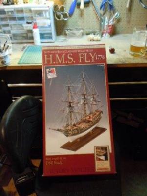
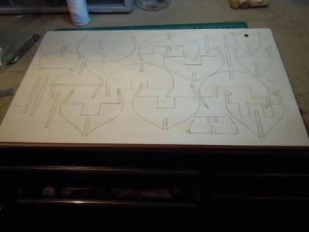
Greetings everyone -- Here I am venturing on a new log and a new build. First off, even before posting any photos, I want to mention that the reason I'm building The Fly is that back in August of 2011 (this was obviously in the Edenic days of MSW 1.0), I noticed an announcement that a kit had been donated to MSW and was available to anyone willing to make a reasonable donation. The requested donation was significantly less than the market price of the kit. And, well, I'm the person who made the donation and got the kit. So here's yet another reason MSW has supported Ship Modelling! To the build. First photo, The Box: This makes it official that I am modelling The Fly 1776. (Note the tidiness of my workspace.) As I took out all the pieces, I thought they looked pretty doggone good. I've been looking at the different sheets of drawings (Tavole? Excuse my Italian if that isn't the correct plural of Tavola). They seem pretty clear, though I began to wonder about certain details that I wanted to see. Ok, now I'm getting started: This is the plywood sheet of Bulkheads that I spent last evening cutting and snapping out. As I was doing so, two questions came to mind. The first has to do with the Captain's Cabin -- and this question arose largely from reading the logs of other builders of The Fly and Pegasus -- If I did want to have an actual cabin (and I do), and not just an external depiction of one, then I would have to do some refashioning of those aft-most bulkheads. Something to think about there, and maybe now's the time? Second question: Here you can see The Fly's stem piece alongside a prototype of sorts that I made for my previous build, The Rattlesnake. The stem for The Fly is walnut, and fits into the keel with all the ease of a work of nature. But it's a single piece. The stem I made for the Rattlesnake consists of multiple pieces of boxwood jointed together with scarphs, which strikes me as being more historically accurate. Now, I am thinking, thinking (and maybe too much) that at least some planking with boxwood would look nice. On the other hand, I have admired the coppered bottoms of several other builds, and if I went that route the scarphing joints would be covered. Since I don't have the actual plans of The Fly or any Swan Class Sloop, deciding how to mark and cut the pieces for the stem would entail a good bit of guess work. And guess work contradicts "historical accuracy." One more factor in this decision: I looked over Greg Herbert's account of building the stem, and saw that he used a mill. Well, my work bench is complete, and it's time to mount my mill. Here's where my decision stands at the moment: I have the boxwood stock, so I think I'll do some configuring, cutting, and gluing, and see how it looks. If it's a bust, I can always use the kit supplied piece. Cheers, for now, and please feel free to comment, make suggestions, warnings, etc. Martin
- 467 replies
-
- 3
-
-
- fly
- victory models
- (and 1 more)
-
Hi Scott -- Welcome to the Magnifying Glass Crowd! The regular sized burrs you buy at Lowes or someplace for the Dremel are always way too big to do that kind of detailing. Your work with the knife achieved a laudable result. You might track down Bill Short's guide to carving with Dremels, though, just because he offers some really good advice on technique and where to get hold of micro burrs. Glad to see you're making terrific progress -- Cheers, Martin
-
Well, there you are! A problem solved is a big lesson learned, and here's hoping that all future followers of Bob's Practicum find your solution. Those will be good looking tops. Cheers, Martin
-
Hi Kenneth --- Glad to see you're still at work on the Rattlesnake. Your planking looks nice and smooth, obviously from that sanding boot. Maybe you should get a patent! Cheers, Martin
-
Thanks a lot, everyone. It's great to have a community to share one's labors of love with. Cheers, Martin
- 104 replies
-
- 1
-
-
- rattlesnake
- mamoli
- (and 1 more)
-
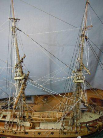
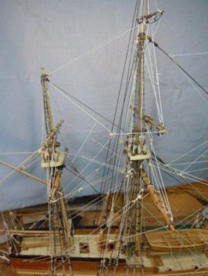
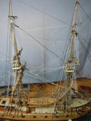
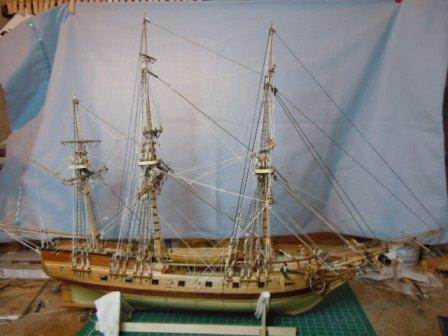
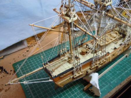
Greetings -- In hopes of punctuating my admittedly desultory log with some final pictures, I "borrowed" a blue pillow case to hang behind the rigging. The effect is far from professional, but maybe some details show up other than the flotsam of my bench. First off, here's a view primarily of the Mizzen: And here are the Mizzen & Main: Main & Fore: The Foremast really does not slouch like that. This a photographic distortion that I noticed only on the "big" screen of my computer. -- And I also notice now that the focus isn't the finest (so much for the Auto feature on my CoolPix). And then here is a full broadside: And I would post a Glorious Conclusion Shot of the Rattlesnake on the mounting board, and perhaps even in her final berthing, but two little hiccups happened. First, as I was trying to affix the mounting screws, I grabbed with a bit too much force and . . . Snap! And then I noticed that the brass pedestals that I had had the foresight to buy at least a year ago are the wrong size. So she sits on the bench still, waiting for the delivery of new pedestals, and for a re-attached rudder. Nonetheless, this does mark the (perhaps inglorious?) conclusion to my Rattlesnake, my second build. This took me 4 years and 2 months. Like Jon Gerson, I followed Bob Hunt's practicum, and must say that I learned lots in how to work with wood, how to use tools, and how to believe that in fact I could attend to tiny details. I also left the practicum behind when it seemed to have more and more errors. And that time coincided with starting the rigging. Thanks to all who offered advice and help. Now off to The Fly -- Woohoo! Cheers, Martin
- 104 replies
-
- 2
-
-
- rattlesnake
- mamoli
- (and 1 more)