


DaveRow
-
Posts
661 -
Joined
-
Last visited
Content Type
Profiles
Forums
Gallery
Events
Posts posted by DaveRow
-
-
-
Hi Pat,
The Funnel came out very well for 3D printing. Impressed I am.
The printed surface, as you have found looks smooth, but rippled with the layering of the filament.
I've bought small diameter nozzles to install on my 3DP, aim is for thinner layers > smoother finishes.
All learning on this method.
Cheers
- BANYAN, cog, popeye the sailor and 1 other
-
 4
4
-
Shipyard Update:
Main Yard Blocks:
The shipyard has been working on the Main Yard, busy selecting the blocks, adding the rope work to each, then secure to the yard.
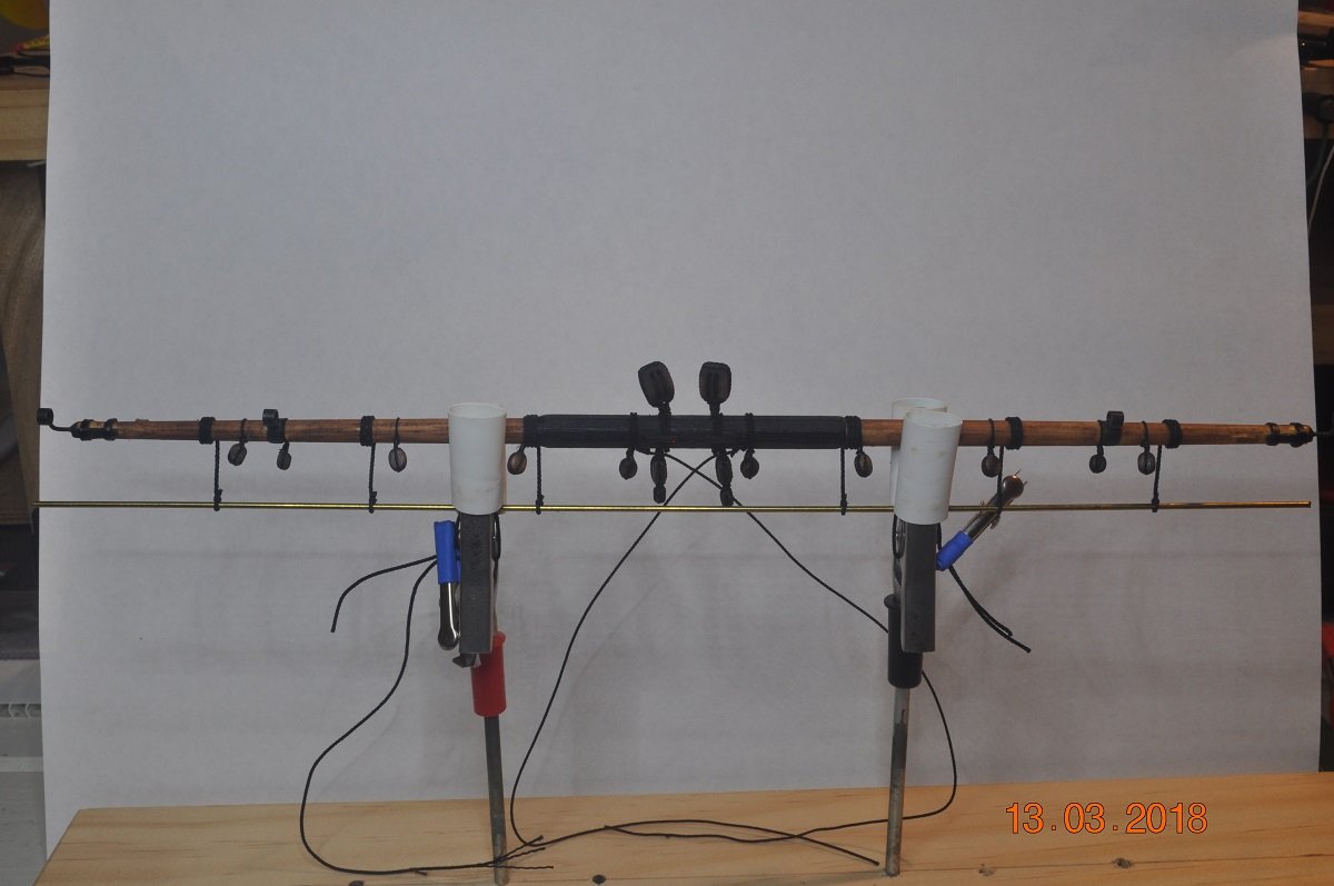
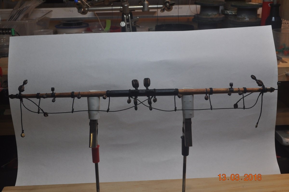
Picture below of the Yard to date.
Nearly ready to add to the Main Mast jeers and hoist away.
Parrel and running ropes to add.
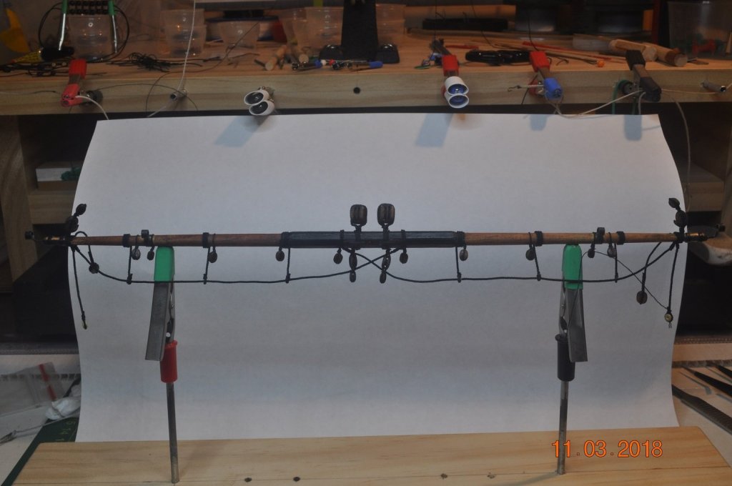
Above: Main Yard; 12 single blocks, 2 double Jeers, 4 twin(2 blocks each) and 2 Pendant/thimbles.
I actually have made all these blocks at the same time for the Fore Yard.
Each loop tightened once in position on the yard.
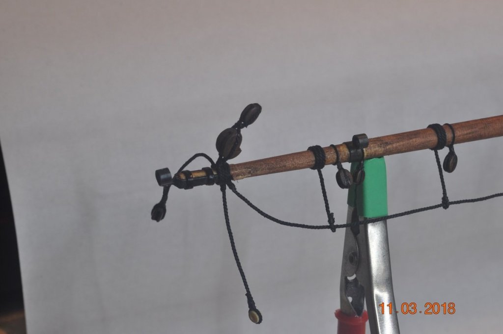
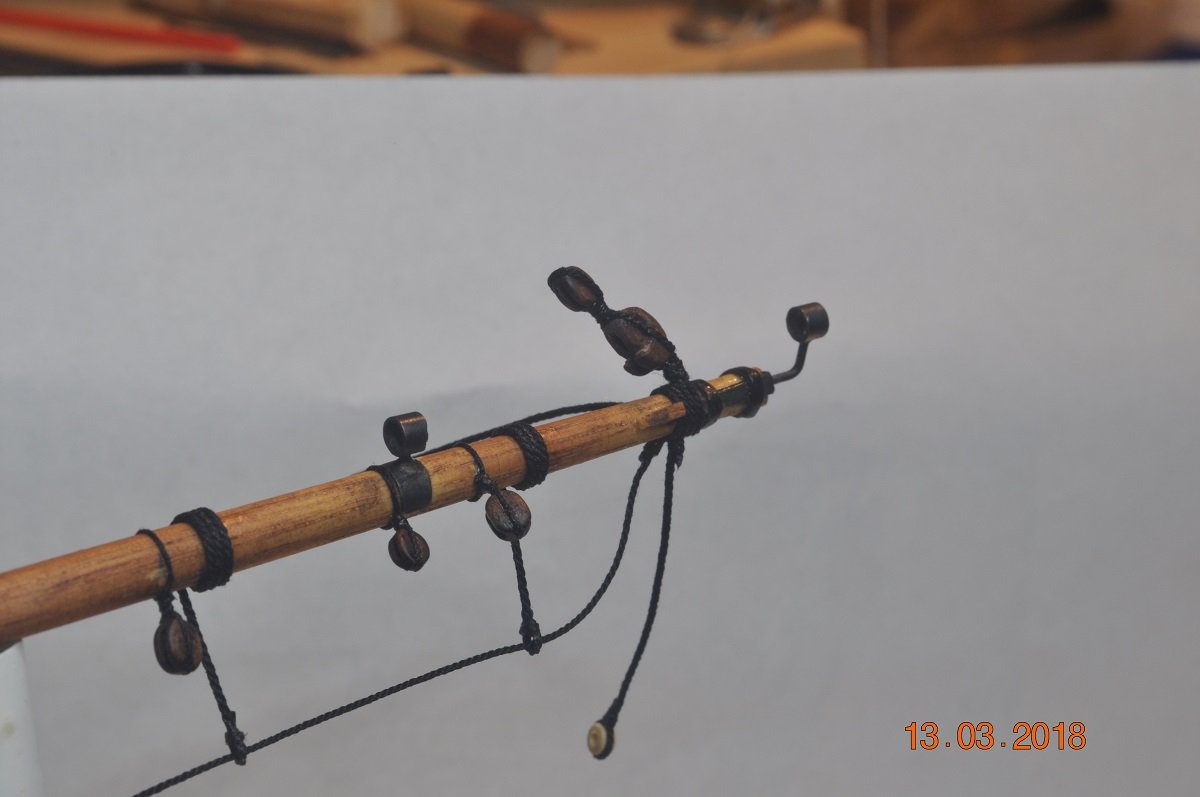
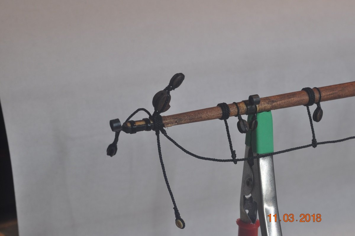
Yard Starboard end:
Lift Block (4mm) & topsail sheet block (5mm) stropped together on top.
Yardarm tackle pendant hanging from the end.
Brace Pendant Block (5mm) on the far side. 1/3 length of the yard.
Start of the Horse with stirrups wrapped 3 times around the diam.
Outer tricing block (3mm)
Leech/Buntline blocks (4mm) 1/4 way/point on the yard
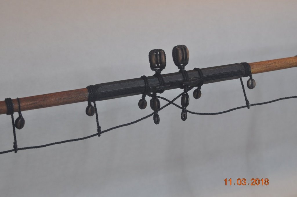
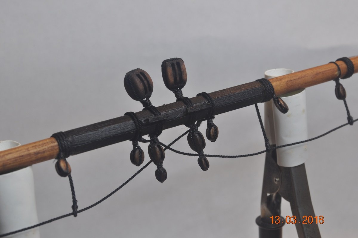
Yard Middle:
Pair of Double Jeers(7mm) on top.
Yard Block (4mm).
Topsail sheet block (5mm) with Quarter block(3mm) stropped below the Jeers.
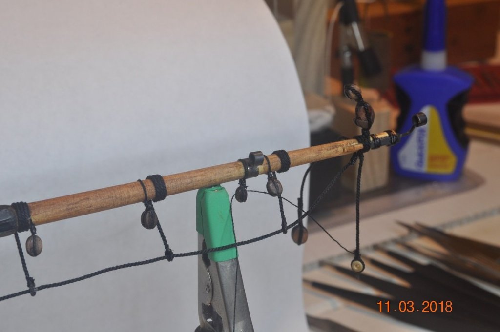
Yard Port end; same as Stb. end
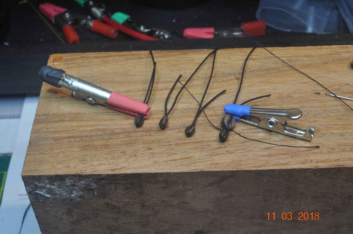
And some detail shots of the blocks being made:
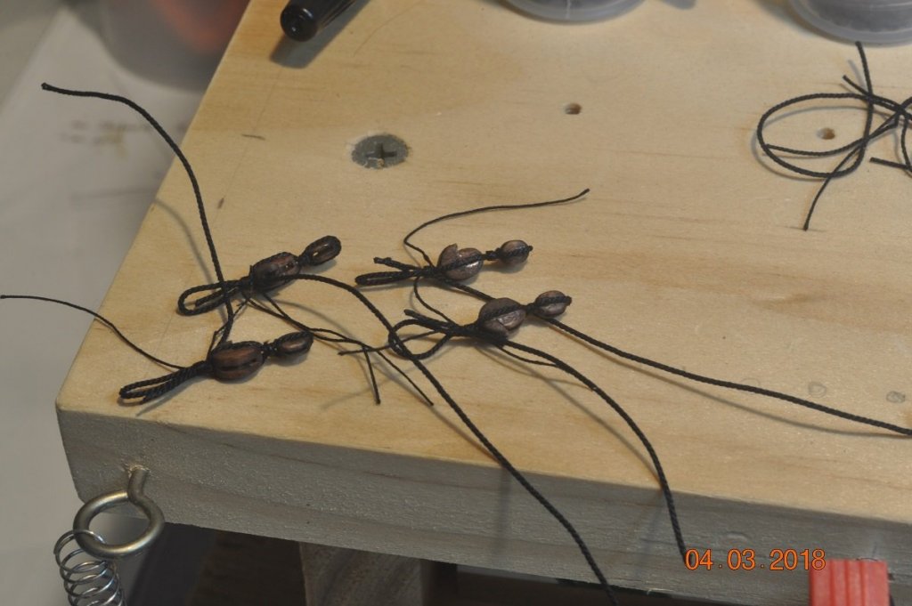
Lift Block & topsail sheet block stropped together. 2 each for Main & Fore.
Yardarm tackle pendant, 1/4 length of the yard.

Quarter block with topsail sheet block stropped under.
Onto the Fore Yard next.
- RGL, paulsutcliffe, BANYAN and 3 others
-
6
-
1 hour ago, BANYAN said:
i Dave, thanks for looking in. The printer is one of 2 a mate of mine purchased; he is a wiz at 3D and G code and rather than learn even more skills before I have mastered the few I have,I have taken up his kind offer to produce these for me
")
cheers
Pat
Lucky you.
I've cracked the G Code, read up on how it works and adjusted it for my printer startup.
I use "Simplify3D" to send the commands to the 3D Printer. So many settings in the program to fine tune the output, one can spend hours testing.
Hope the Capstan turns out well.
- cog, mtaylor and popeye the sailor
-
3
-
1 hour ago, BANYAN said:
Many thanks for looking in and your kind comments Jason, I'll keep you posted on the capstan. Latest attempt allows most of the detail to be presented such as the capstan bar holes etc, but the bar locking pins are proving too much for the printer at 1:72. The hardest part will be trying to paint this as I have developed the 'old fella' shakes
The doctor suggested I have a few drams the night before (but was careful to mention that he was not encouraging me to drink :))
cheers
Pat
I will be waiting to see how it turns out from the 3D printer Pat.
Did you buy a printer or you using a service ?
-
What fantastic workmanship Johann.
Total admiration for your jigs and patience, the way you create all those metal parts is a credit.
- EJ_L, aviaamator, BETAQDAVE and 2 others
-
5
-
-
On 2/16/2018 at 9:04 AM, stevenmh said:
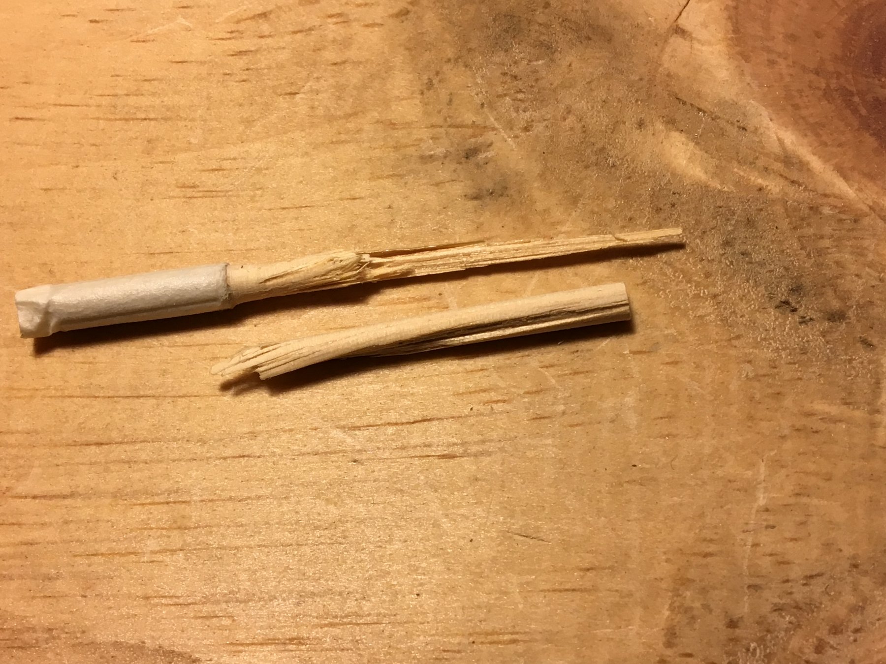
I've made a "lathe" using an old drill and had success with the slight tapering required for the main and top masts of my Mimoli Constitution cross-section. However, when it came to shaping the yards, disaster struck - happened on both the main and topsail yards - the diameter at the ends is supposed to be about 3mm.

I'm a bit fearful of trying to shape the top-gallant mast and yard and the royal, since these all need to end up much thinner than 3mm.
Is there some trick to this that I am missing? Do I need a drill with less torque? Am I making a big mistake using the dowls that came with the kit - if so, what wood would you suggest?
Hi Steve,
To add my experience of lathe work, esp. with small diameters.
The dowel in the picture you originally posted(above), exhibits a twist in the longitudinal direction.
This in MHO is caused by too much torque, either at startup or even when the motor is suddenly powered down at end.
Meaning their is not enough dowel diameter to resist the rotational(torque) pressure on the dowel.
A variable speed motor I have read should be used at startup to slowly rotate the work piece up to speed, then slowly reduce at end.
I had several disasters after shaving down to a couple of mm. But my Lathe does not have a variable speed motor.
-
Shipyard Update:
Thanks for looking in on the progress fellow shippy's.
Mast Yards - Parrels:
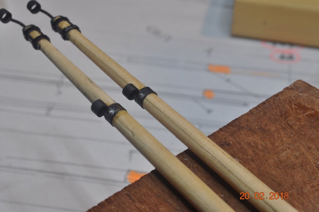
I decided to create a smaller Parrel set for the smaller masts.
The 10mm set seemed too big to wrap around the Main, Fore & Mizzen TopMasts and outer Bowsprit yard.
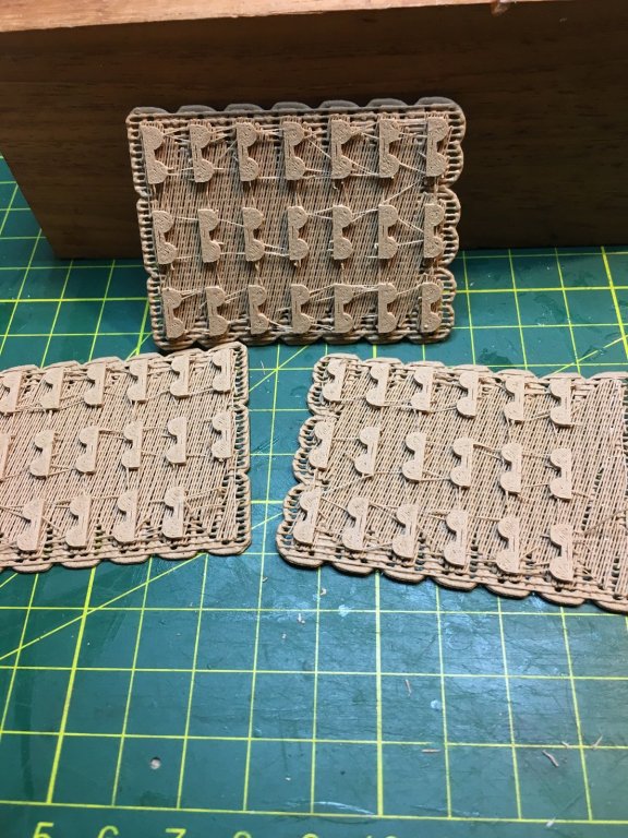
Below is a 7mm version 3D printed in wood filament, with small 2.4mm brass trucks(balls).
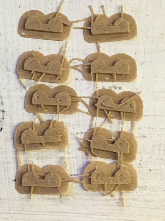
Above is straight off the bed of my 3D printer.
I still get a drag of filament between each item, but it is easy to trim off.
The back(the sacrificial bottom layer) just peels off.
A few little holes, but a sand, stain and at the scale you don't see it.
A Jig to hold the Ribs whilst the holes are drilled as before.
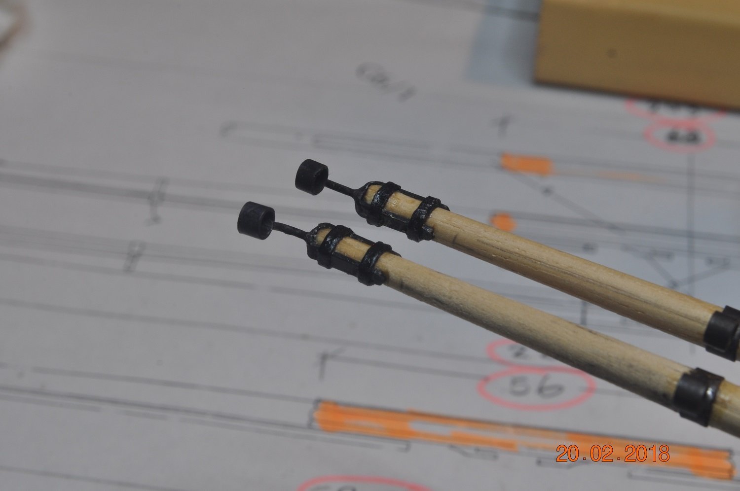
A trial Parrel set made up.
Ribs ready to drill at the bottom.
7mm Parrel wrapped around a 6mm dowel.
Same 7mm Parrel around a 6mm dowel.
Lots of blocks, ropes to go now.
-
Shipyard Update:
Mast Yards - Blocks and Parrels:
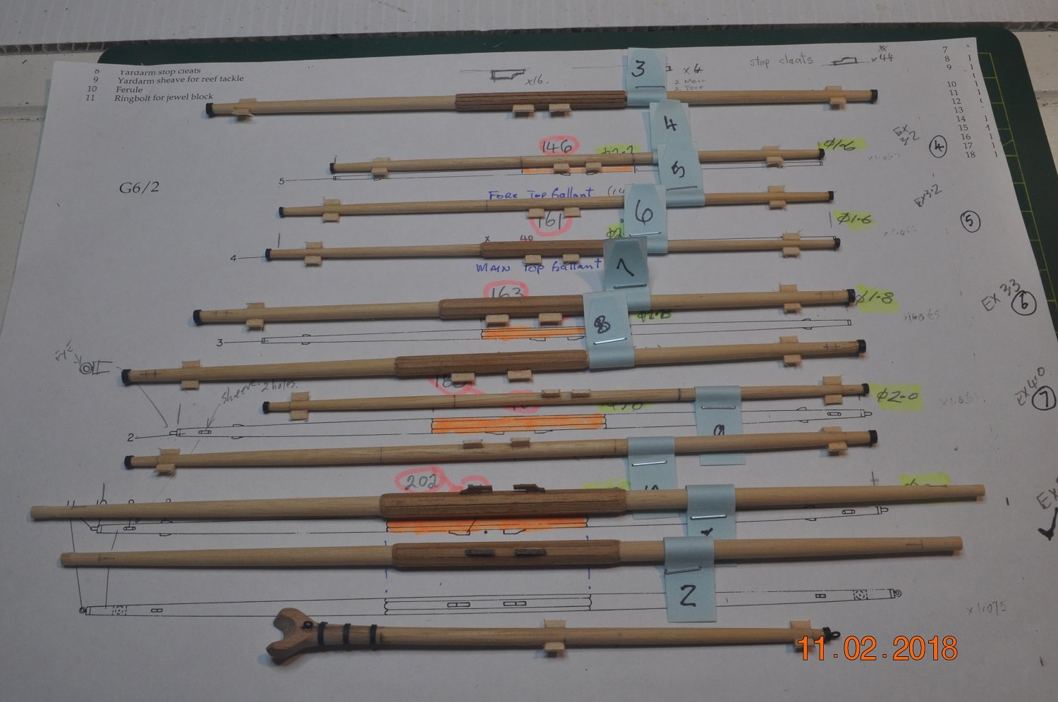
A bit of an update the the Yards.
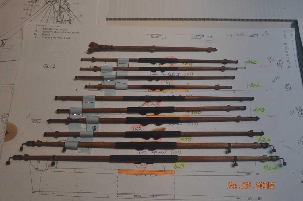
Above are the 11 Yards with the various Tye & Stop cleats, Ferules on the ends, and the main & fore fitted with boom irons.
I decided to paint the central areas Matt Black and the outer ends with a cedar wood stain.
Next was onto the blocks, ropes and Parrel fit-out to the various Yards:
What has taken a lot of time, was working out the sizes of the many blocks.
Being my first model of this nature, learning a lot along the way, making it up as well...
Many resources have detailed pictures and rope sizes, my kit plans were again useless again in this area.
The AoTS indicates with scale the various attachments.
Using David Steel's Rigging Tables, I hope I have worked out the block sizes to use.
Jeer Blocks:
I started with the Fore Yard Jeer blocks - 2 x 7mm double(7mm because this was the size I used for the mast blocks)
Double strops derived from a trial fit around the mid section of the yard.
One completed.

2 Jeers on the yard, temporary fit.
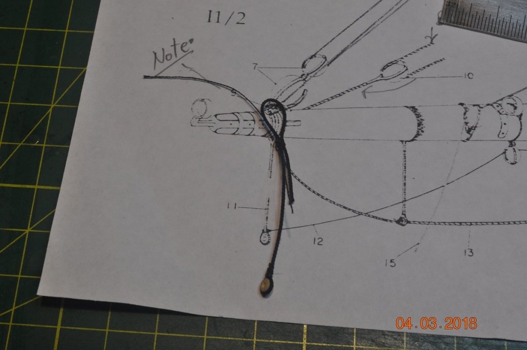
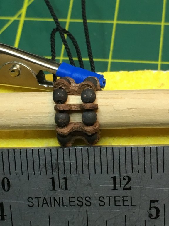
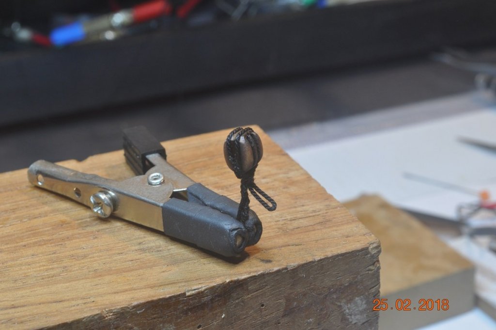
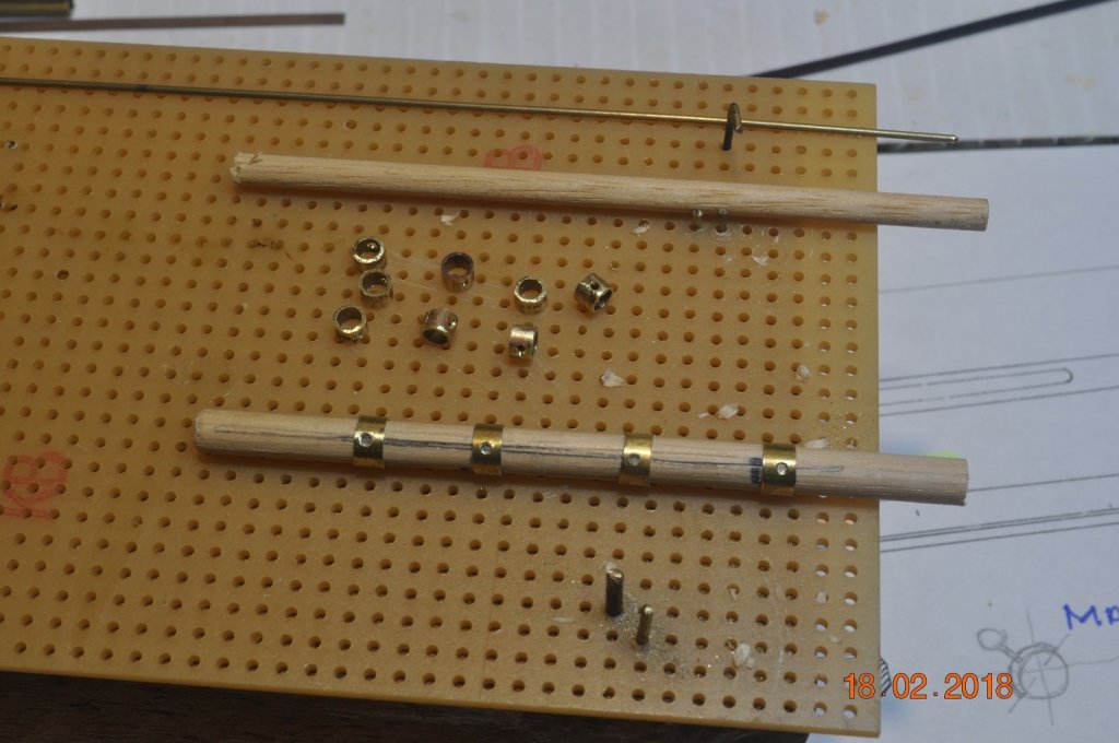
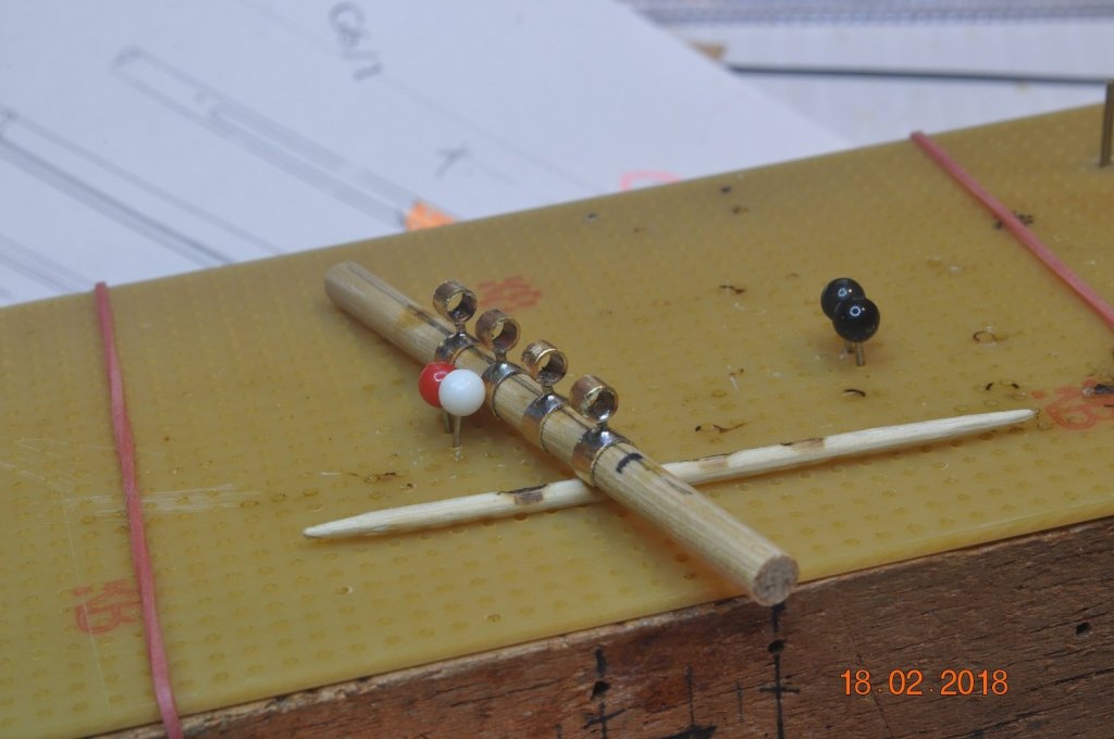
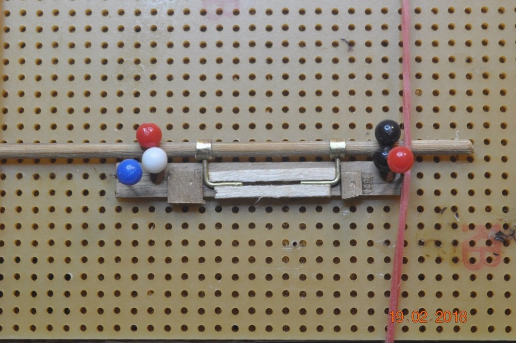
The Parrels:
My kit did not have any Parrel parts.
Define parrel: a rope loop or sliding collar by which a yard or spar is held to a mast in such a way that it may be hoisted or lowered.
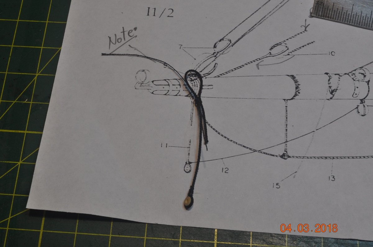
I noted in Pay Banyan's log, Steve had dropped in a Parrels page from "The Anatomy of Nelson's Ships".
The Ribs being 2' long and 8" wide.
At 1:60 equates to !10mm x 3.4mm in frame size. 2" tick ~ 0.84mm
Why not use my 3D printer with wood filament to create the Ribs.
I won't go into the process, however printed 3 sets of Ribs, shown above.
They are a bit rough on some of the edges, but after some sanding come up quiet well.
Above the Jig for drilling of the rope holes. The top Rib is not formed well, so used as a drill template.
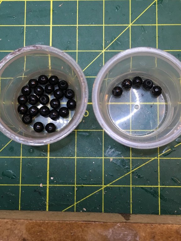
The black beads(for the trucks) are 4mm dia, a bit larger than I wanted, and not oval as in the Parrels page from "The Anatomy of Nelson's Ships".
However make use of what one has on hand.

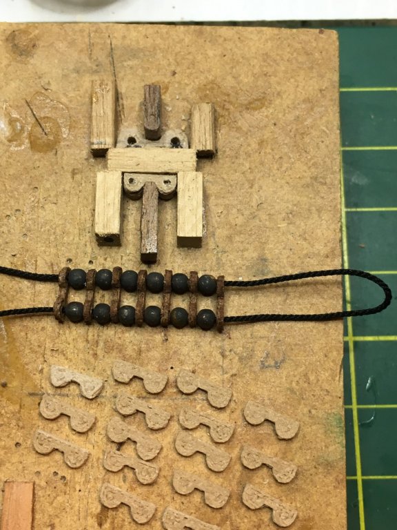
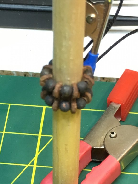
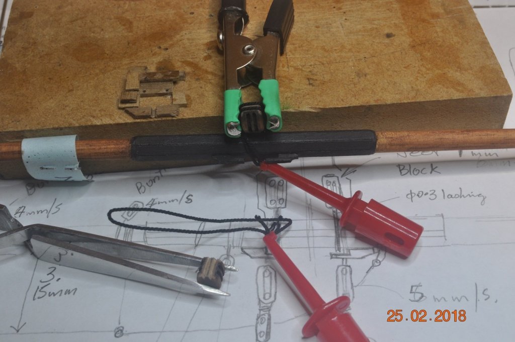
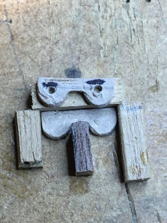
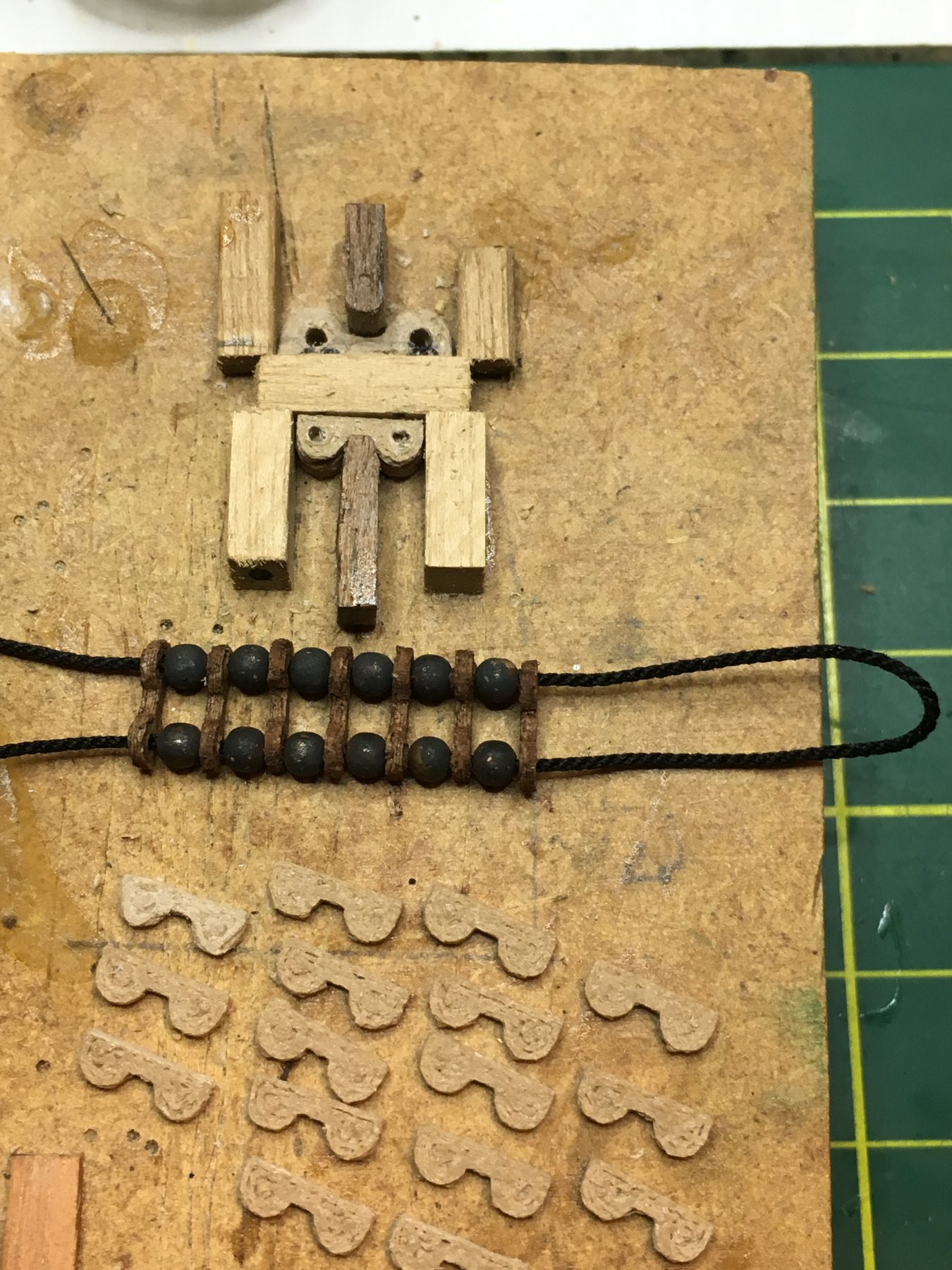
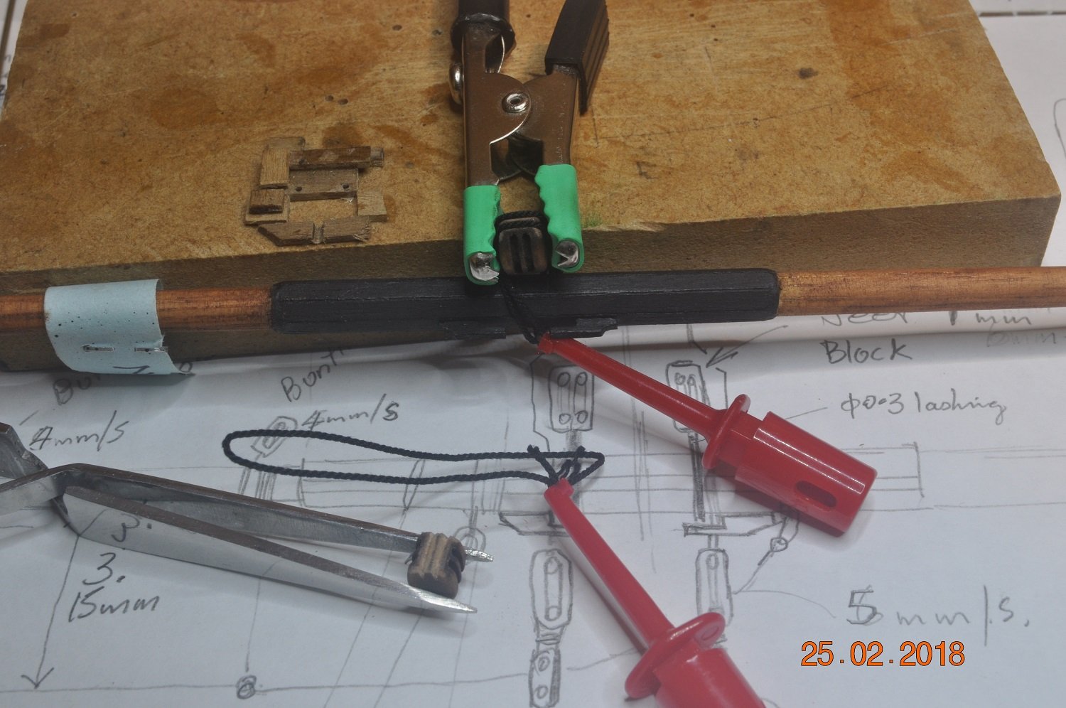
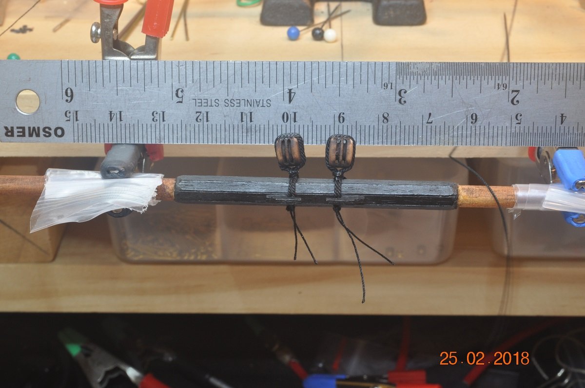
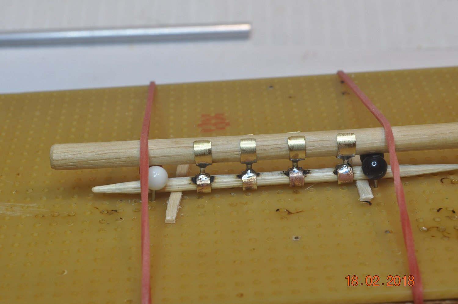
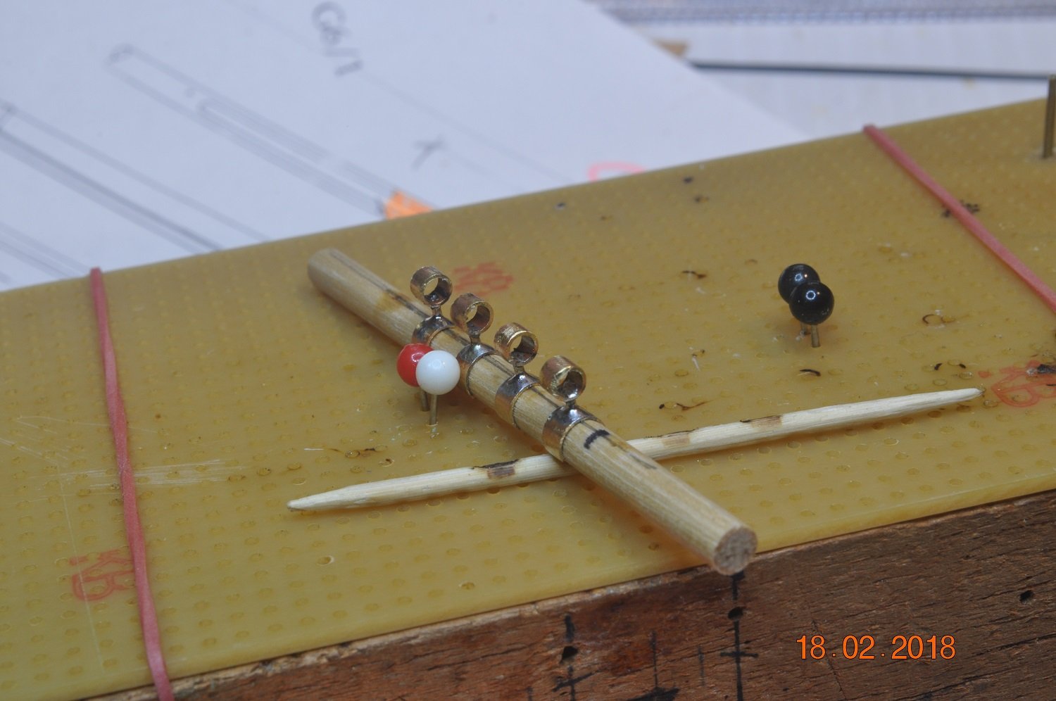
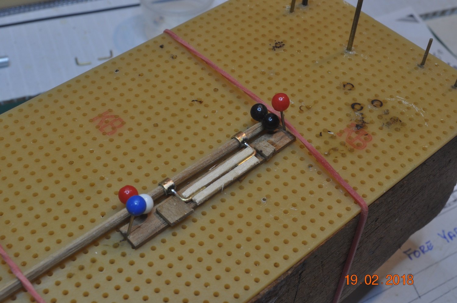
Above shows:
1. To the right a jig for drilling the 2 holes for the rope to pass through.
2. In front, some Ribs sanded and drilled.
3. Each Rib I stain and later will clear coat.
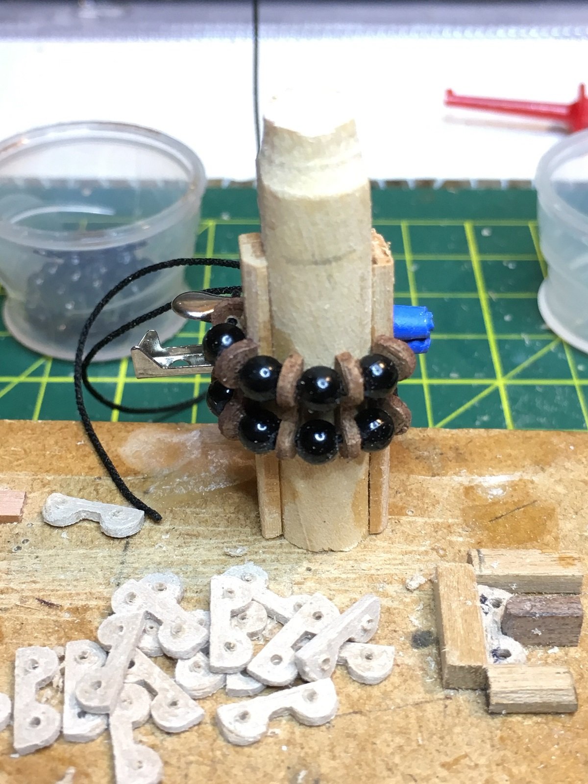
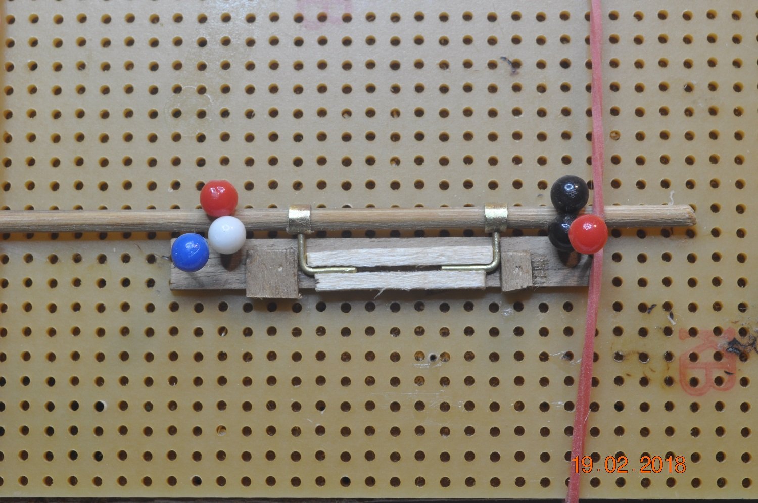
4. A test setup of the Parrel on a mock-up section of Fore-mast
At this scale, all the little errors disappear.
I am concerned though the scale is a wee bit too big, may be fine for the Main and Fore Yards.
Might need to scale the set-up down for the smaller yards.
Lots more thought to go into all this yard rigging and fit-out to go on with....
-
-
Hi Pat,
Thought I'd take break from my build and see what is going on elsewhere.
The painted hull is looking great.
How are you going to build the Capstan ? any 3D printing involved ?
I'm jealous of a trip to the UK, visiting a number of the maritime museums.
Something on my bucket list.
-
-
9 hours ago, robdurant said:
Those look fantastic. So helpful to see the way you've gone about making the parts ready to fabricate these parts.
Hope you don't mind my asking what may be a silly question... When you say weld, is that tin and lead soldering / silver soldering or another method, and do you add flux separately or use fluxed solder? I've done some electrical soldering, but never had much success with brass parts... perhaps because my soldering iron wasn't powerful enough. Those jigs look really neat, though, and the result speaks for itself!
Hi Rob,
Nothing silly going on hear.
I use a Resistance welder, an American Beauty Super Chief 250, adapted to 220v for AUS.
Works differently to a Soldering Iron(where the area around is heated up).
Pat(Banyan) from Melbourne put me onto this system. Imported from USA to AUS. Not cheap.
The 2 prongs(on the hand piece) heat up the area between the prongs in a flash(like in a micro second), and applying/regulating the amount of lead/silver solder creates the joint.
Takes a bit of getting used to, however I am so impressed how fast it makes the joint/s.
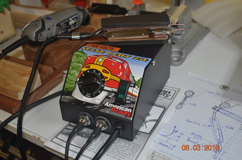
The system I have above.
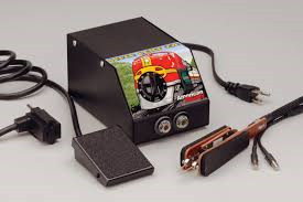 Kit from www.americanbeautytools.com
Best results I find setting the parts up in a jig, flux the joint where I want the solder to end up.
Touch the ends of the prongs to either side of the where you want the soldered joint.
The current is via a foot peddle(like on a old Singer sewing machine) to activate the electrical current to the hand piece/prongs.
I first starting using the resistance welder in March 2016. See my posts about that time for more info.
Pat has info on his Endeavour build as well. Hope you don't mind Pat for the ref...
And the type of lead/silver % solder makes a difference as well.
Hope that all makes sense.
-
Shipyard Update:
Mast Yards - Studding-Sail Boom Irons:
The Main and Fore Yards have Boom Irons fitted to hold the Studding-Sail Booms.

Above are the Inner & Outer Boom Irons fitted to one end of a Yard.
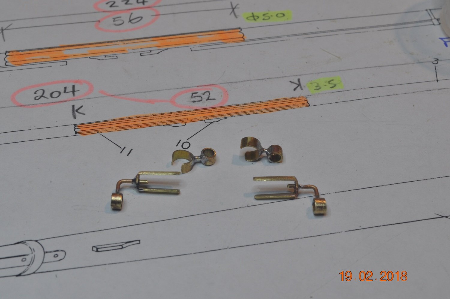
The parts and process:
INNER BOOM IRONS:
Two(2) sizes of brass tube were cut to make rings, 1 for the Rings(for the studding-sail boom to slide through) and the other for a collar onto the yard itself.
0.8mm bar was used for the neck to join the rings to the yard. According to "Dave Steel" the neck was a square bar, which I did not have. Rod instead.
Each ring and collar has a hole for the neck rod to fit into.

I made a jig to hold the 3 parts together for welding the 4 assembles together.
Welds complete.
OUTER BOOM IRONS:
On the end of the yard/s a same size Ring, 90deg. neck and straps are fashioned.
Another jig top to weld a pair of rings/neck bar for consistency. Set ready to be welded here.

After welds done.
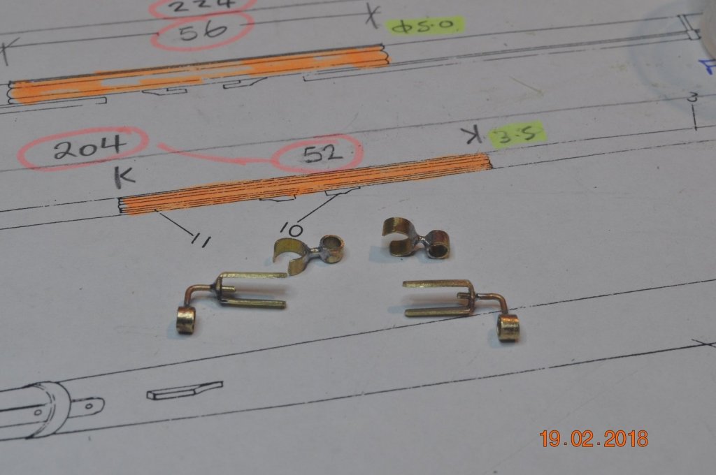
Above are the 4 Boom Irons for 1 yard, removed from the yard ready for blackening.
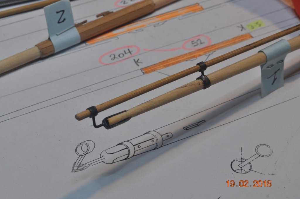
Test assembly on 1 end, blackened boom irons fitted.
2 hoops to fit over the end straps.
-
-
7 hours ago, BANYAN said:
Very nice work there Dave; these look excellent.
cheers
Pat
Thanks Pat,
I realized after reading Dave Steel - Mast Making section last night, the yards with battens in the middle, the stern/rear batten should be longer. Will anyone notice once they are painted black ?
-
Shipyard Update:
Yards are on the build:
We're underway making the yards.

All(11) of the Lower, Top-sail, Top-gallant, Spirit, Spirit-topsail & Gaff(off the mizzen) Yards on their way.
I added a block to shape for each of the Stop cleats and Tye cleats.
Yet the construct the outer and inner boom ironwork. Next task.
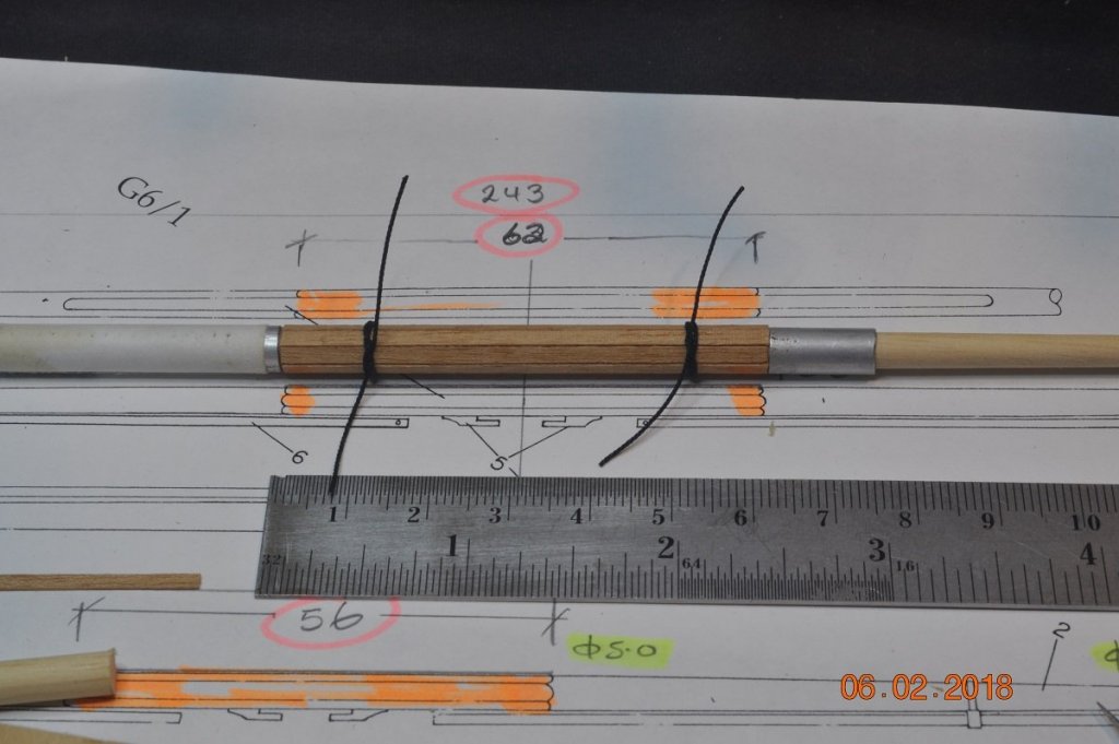
How I added the battens to the mid sections of the Lower & Top-sail Yards.
I used a section of Aluminium tube to square of either end - before round sanding the batten edges.
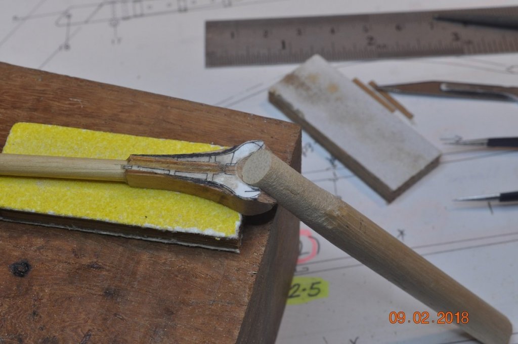
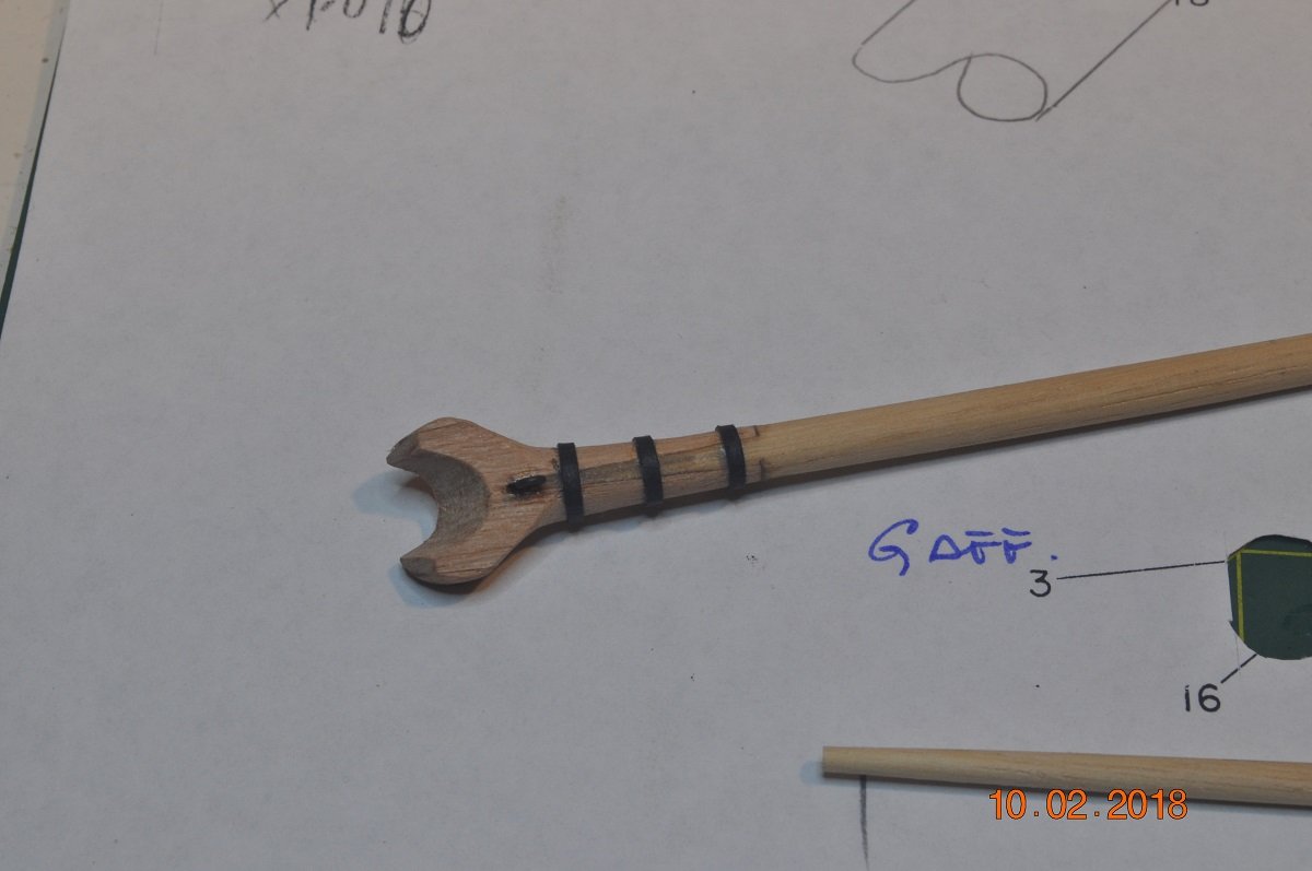
I shaped a dummy mast section to shape the jaw, for a snug fit.
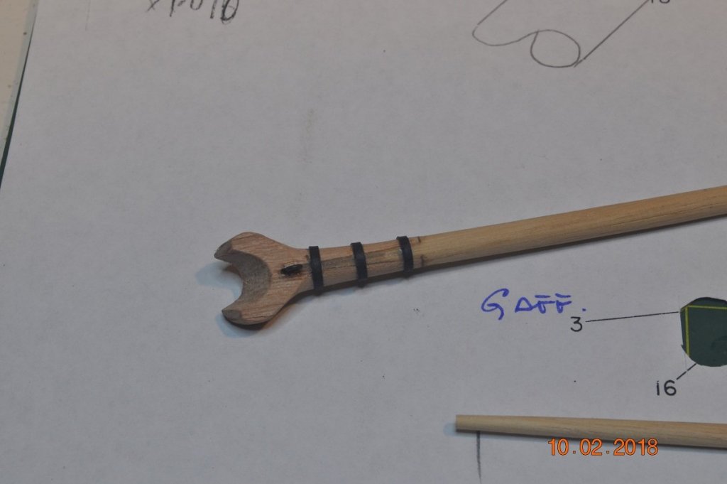
Couple of pictures of the lower end(jaw) of the Gaff, scarf joint with hoops(a wrap of thin black card).
Detail as per AoTS p93
Next to fashion the Boom Ironwork for the Main & Fore Lower Yards.
Must ensure the hoops face forward(eh Pat !) for the studdingsail booms.
- GrantGoodale, russ, zappto and 4 others
-
7
-
You've crafted a nice collection there Greg.
Love the paint-jobs and detail is amazing at that scale.
- Haliburton, Canute, mtaylor and 4 others
-
7
-
22 hours ago, BANYAN said:
Hi Dave, just to clarify, the 'cleats' not the shrouds kept twisting - not sitting at 90 degrees to the shroud (i.e facing inboard); finally sorted doing it in a similar fashion to you.
cheers
Pat
They were tricky little buggers. Glad they are out of the way. I'm onto making the spar blanks now.
-
On 2/4/2018 at 4:25 PM, BANYAN said:
That binnacle came up a treat Dave; nice finishes.
You have also done a very tidy job on those shroud cleats; they kept twisting on me. Seems you found the knack of keeping them straight very quickly
cheers
Pat
Twisting ?
All my ratlines were glued at every shroud intersection, which kept the shroud fixed.
The cleats, held in place with tweezers whilst the middle thread looped and tightened. Then a drop of CA on opp side of the cleat touching the shroud to hold in place. Then finish the 2 outer threads.
Sounds simple ? I've mastered using 2 tweezers(one per hand) at a time.
- robdurant and John Allen
-
2
-
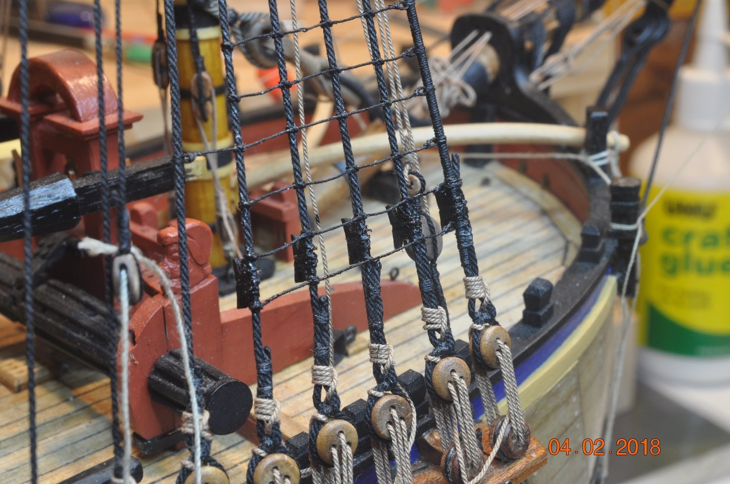
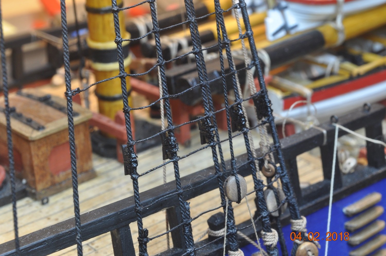
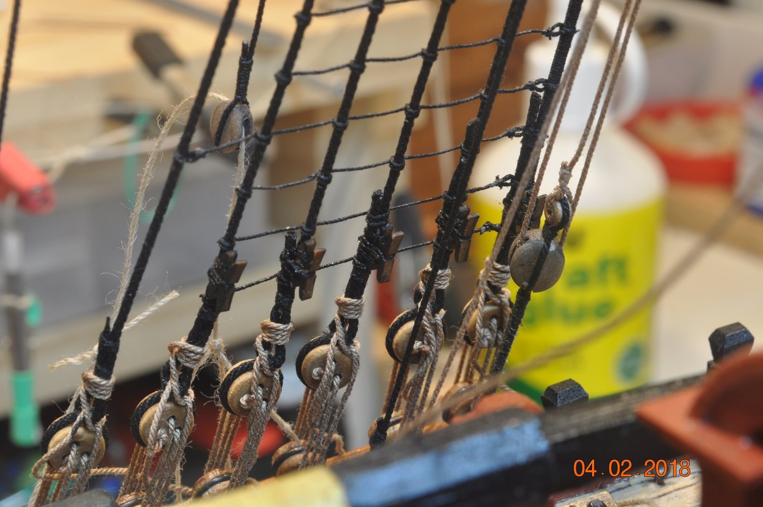
Shipyard Update:
Cleats to the lower Shrouds:
The shipyard took on the task of adding cleats to the lower shrouds.
Tricky little buggers to lash onto the inside of the shrouds.
3 x 2 loops per cleat.
Each cleat had a groove filed to the inside leg to "sit" over the shroud/rope.

Starboard Fore Shroud cleats.

Starboard outer Shroud cleats.
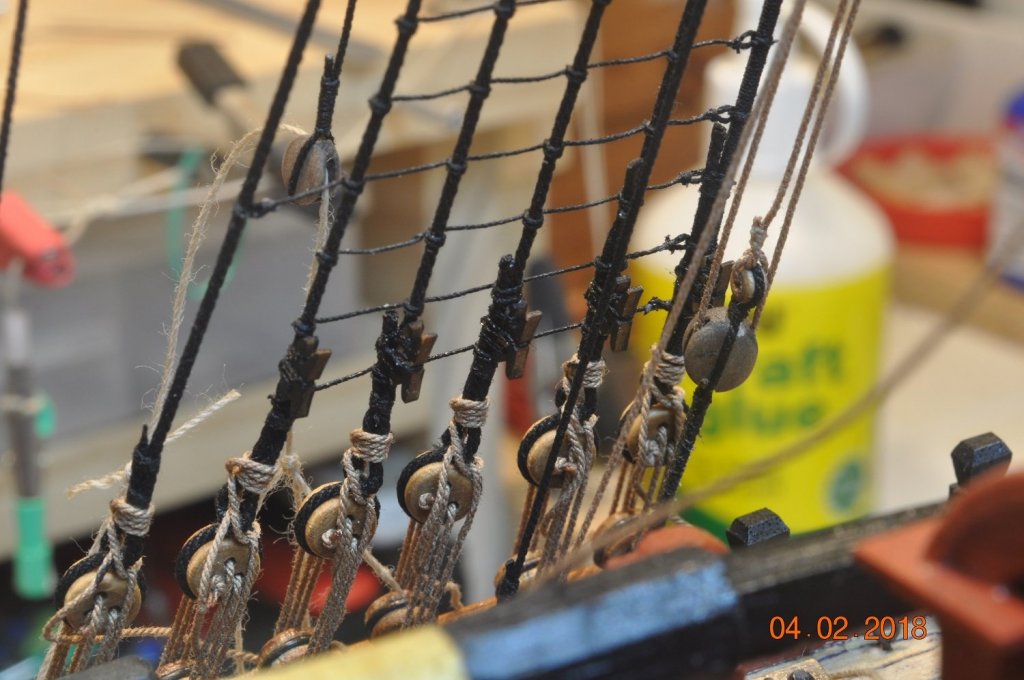
Inner Port view Shroud cleats.
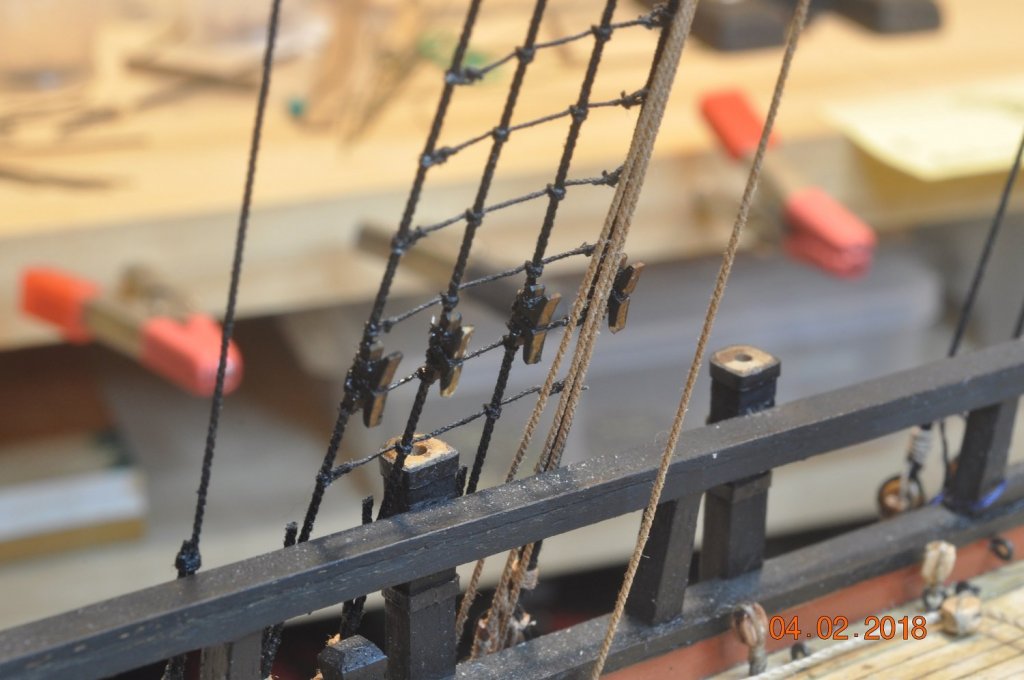
Inner Port Mizzen Shroud cleats.
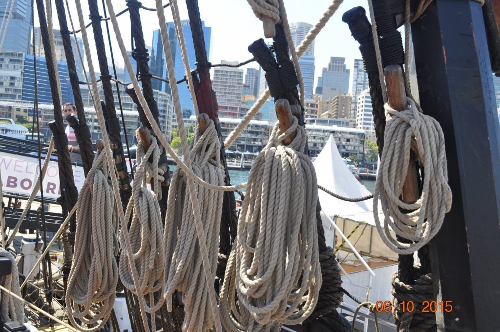
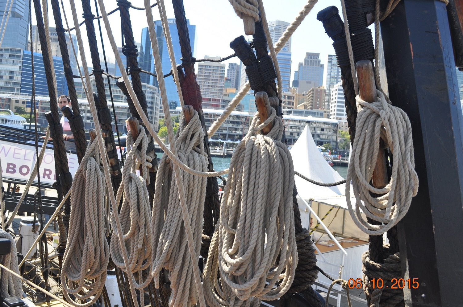
Cleats on the shrouds - picture on the HMB Endeavour Replica at AMM - Sydney
- John Allen, md1400cs, robdurant and 3 others
-
6
-
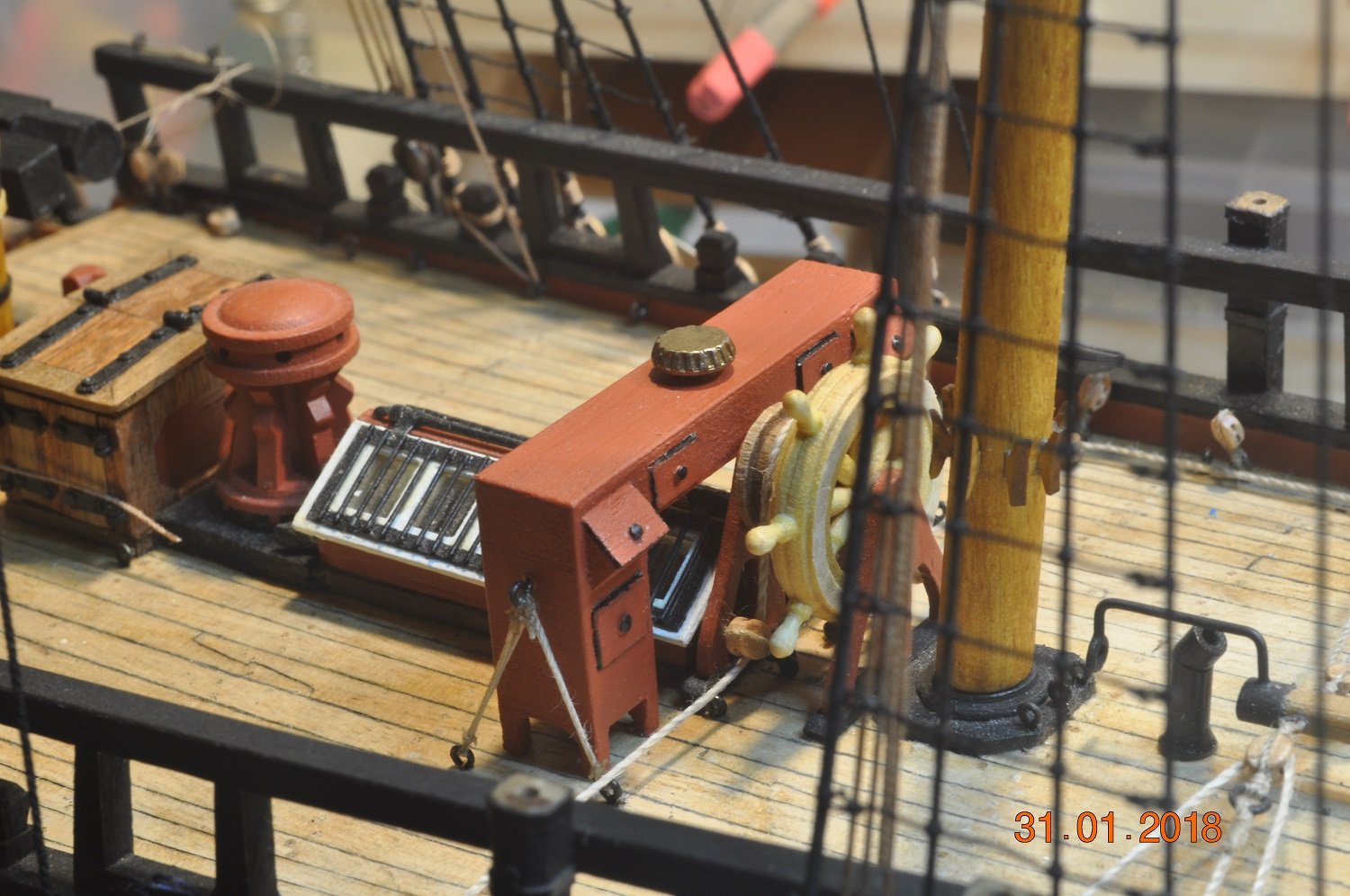
Shipyard Update:
Binnacle completed:
The boys in the yard have lashed down the Binnacle in it's resting spot.
Finished it off with a knob on each draw and the vent in the top for the lantern fumes. Well that's the intent.

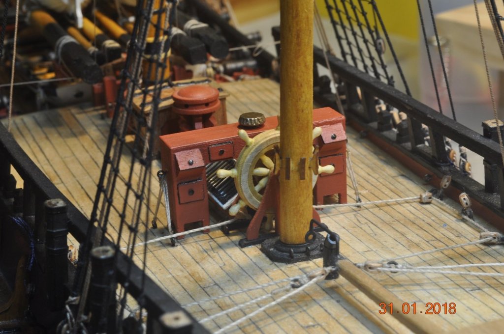
Next was to add cleats to the Shrouds.
- russ, rvchima, John Allen and 1 other
-
4
-
27 minutes ago, BANYAN said:
Now that's the future of modelling
Very nice job Dave, shows what can be done with some modern technology. Some purists may have difficulty with this, but there would have been the same issue with the introduction of PE way back, and look at it now - a staple of many kits.
cheers
Pat
Hi Pat,
Not sure about the "future of modelling"
Certainly has a benefit of reuse of the 3D model to produce at different scale/s.
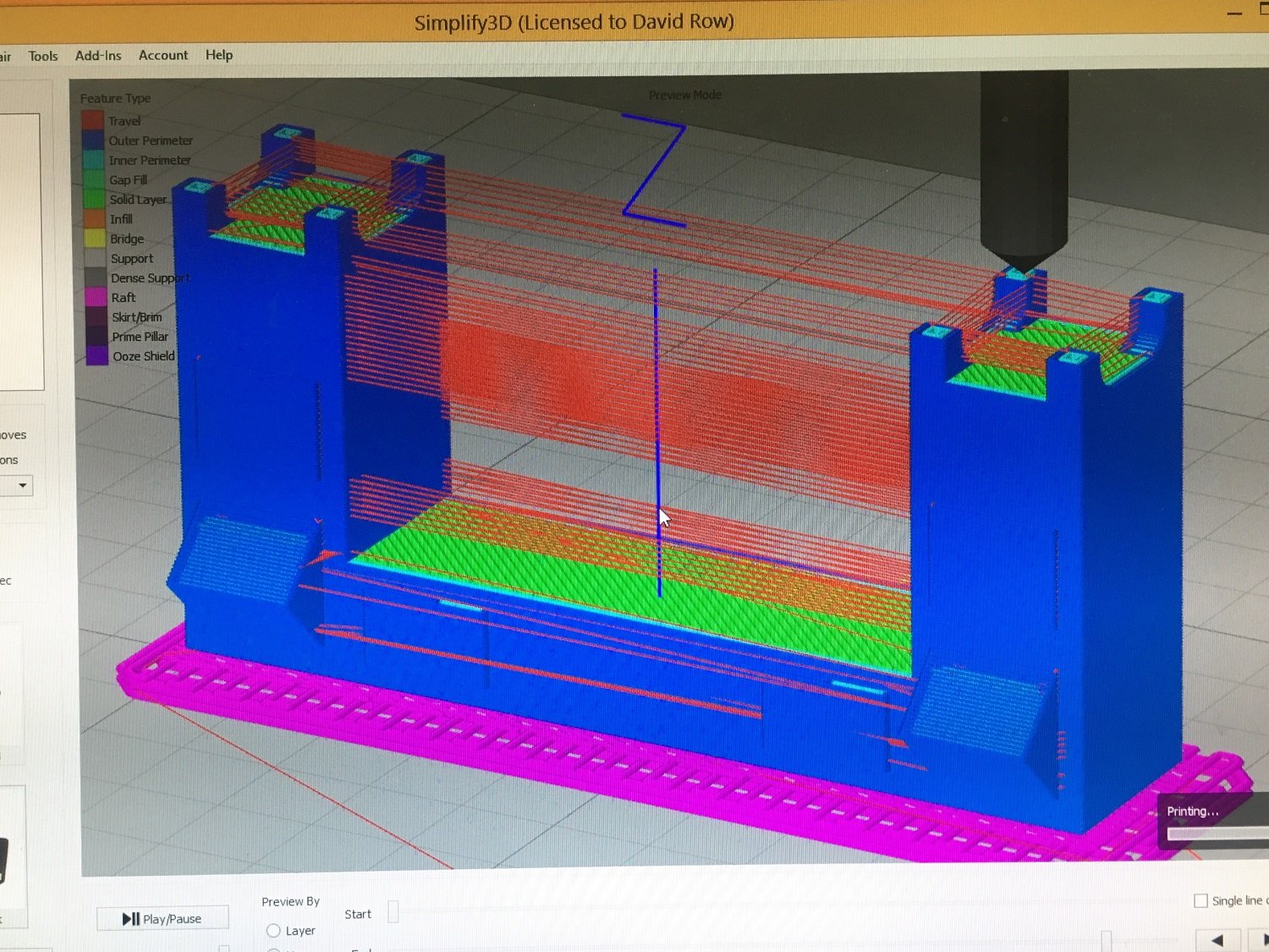
I produced a couple of test Binnacles with the ABS filament, which printed well, then the wood filament was in PLA, a whole different learning curve.
Below is a test 3D print (just after last layer), still on the heat bed. After many changes to settings improved the final print to produce a fairly good final product I was happy with. Still needed some cleanup though, but at least all surfaces were 99% true.
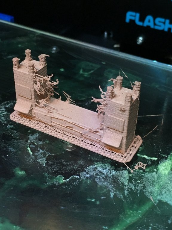
3D printing may not suit all items. Complicated shapes with overhangs fine/thin sections are a challenge.
I printed the Binnacle upside down for the above reason.

I believe the test is to make the item with 3D printer, finish it off(paint, fixings), add to a model and see if it compliments the build in very way.
- robdurant, BANYAN and paulsutcliffe
-
3


HMB Endeavour by DaveRow - FINISHED - Corel - Scale 1:60 - First Build Kit
in - Kit build logs for subjects built from 1751 - 1800
Posted
Hi their Greg,
Actually the traffic I have experienced is pretty dam good.
I am a TX driver, meaning driving Games Family Members(visiting nation dignitaries, managers), Comm Games officials about.
A loot of work went into Games Lanes on a designated road network which I get to drive on.
We have Comm Games vehicles to drive all shift.
Done 7 shifts with 4 to go. Bit tiring, but meeting interesting people from other countries.