

Siggi52
-
Posts
989 -
Joined
-
Last visited
Content Type
Profiles
Forums
Gallery
Events
Posts posted by Siggi52
-
-
Hello HJX,
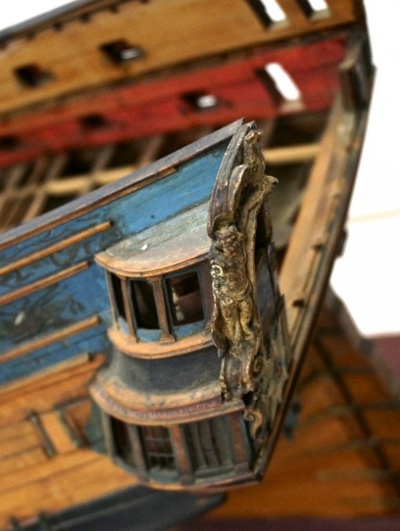
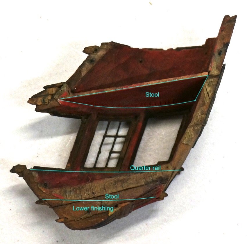
I would prefer your last sketches, but without the step. The stools are deeper than the decks and then you have also more freedom for your head. As in your plan of the Warrior then 7 ft if you measure from rail to rail. In Gaetan's post #455 are two steps down to the stool. Here are an other picture of the Egmond

- mtaylor, Jack H, Captain Poison and 1 other
-
 4
4
-
Hello Gary,
I think you build your Alfred as shown in the plan. With no extra floors ect. Than you are at least right. All other things are speculation. And so step are the stools not, that a seamen would get seasick when entering the gallery.
@ hjx, from wich sources did you get your information of the raised stools ore floors?
I think that you mixed up there some things. At that picture is the lower stool not build. And when you raise the middle stool, than the captain should not be larger than 4,5 ft, ore you have to build the upper stool above deck level 😉 All the stools are build at the inside of the rails and on top of it is a massiv block of oak, the upper stool. Have a look at Goodwins man of war... page 199.

-
Good morning Gary,
it would be interesting if Druxey has any historical information for his proposition. Fact is, that they build more for beauty then for comfort. Otherwise they would have build the stool directly after the sheer of the deck. In the plan Gaetan posted, there are also two steps down drawn in!
At the other hand, you would get problems with your head if you build in there an other floor.
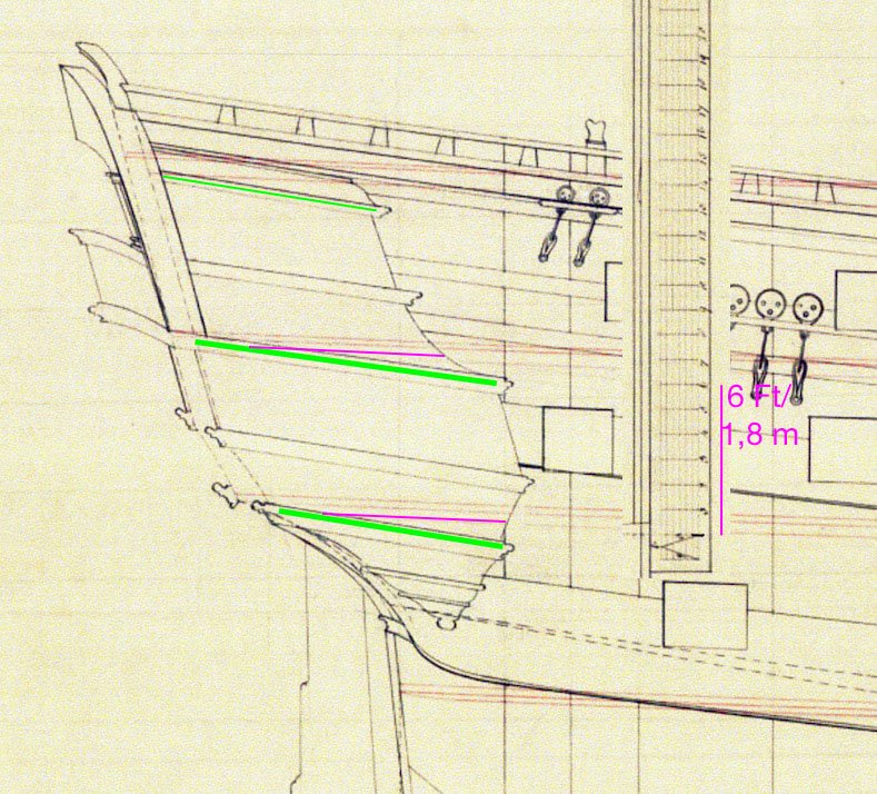
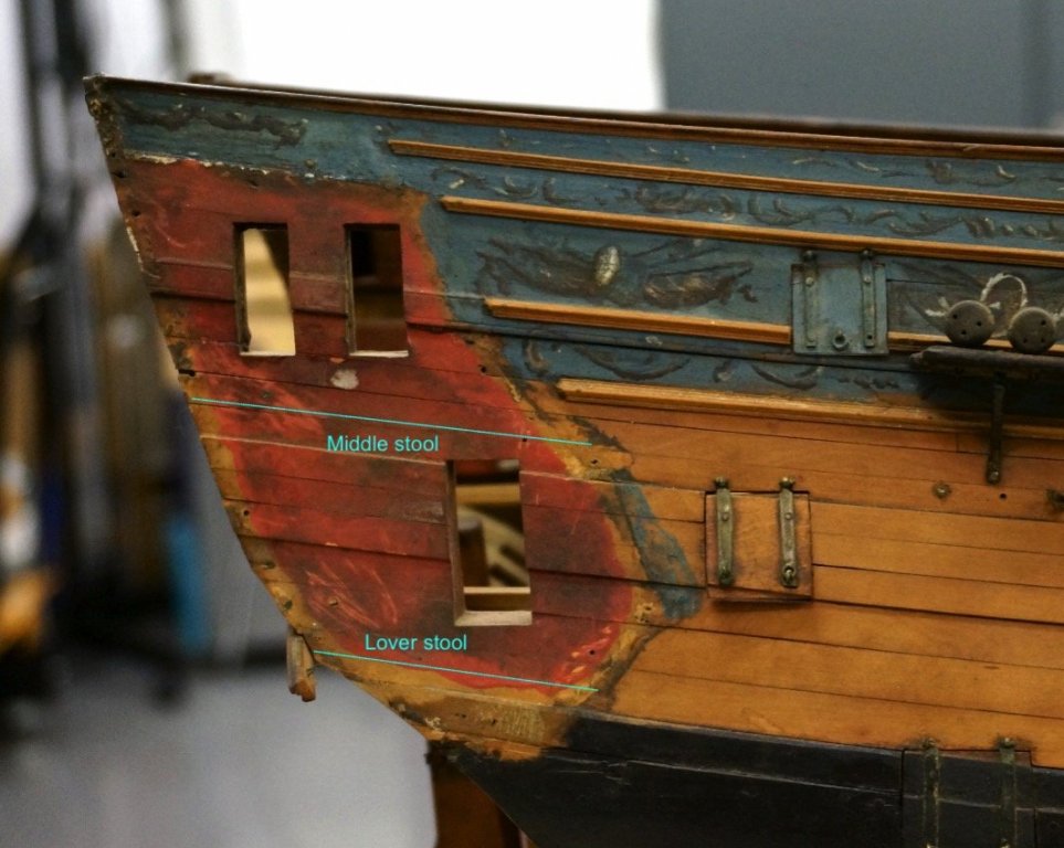
That is the plan for the Dragon and also the Superb. The green lines are the stools and the violet ones the extra floors Druxey prefers. With the stools only, you have there a high of ≈6 ft, ore 1,83 m. So for me, and most people of the 18th century, just enough. With your extra floor in front of the gallery only ≈5.5 ft, ore 1,67 m!
-
Hello Gary,
I do not really understand what Druxey means, but there is no extra floor as hjx means. The stools going also with the sheer and not with the deck.
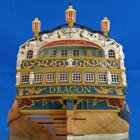
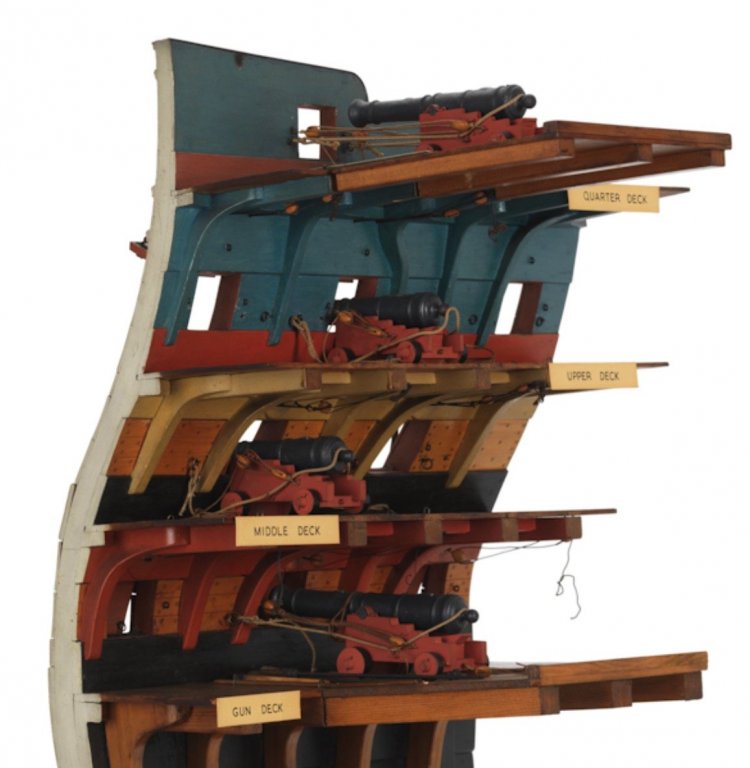
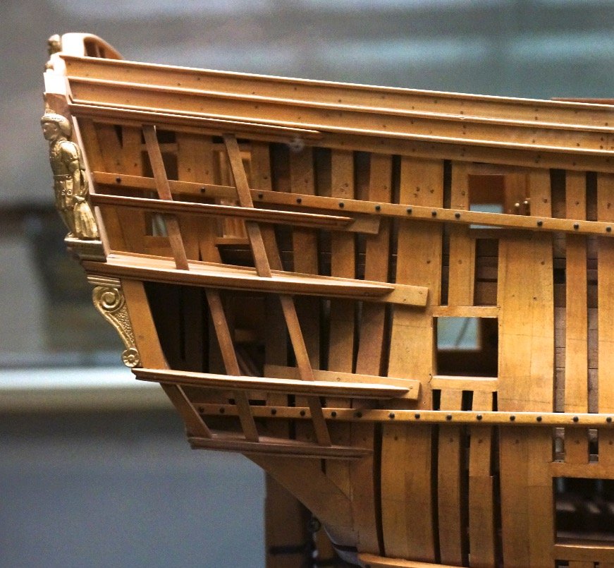
Here some pictures I made from the Superb (1760), sister-ship of the Bellona. The modellers did't work like we do, and build every beam as they are in reality, but you could see the middle stool is build in the direction of the rail and the sheer. (sorry my english!)
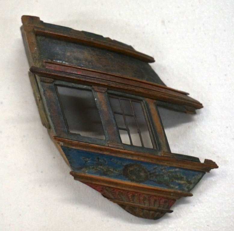
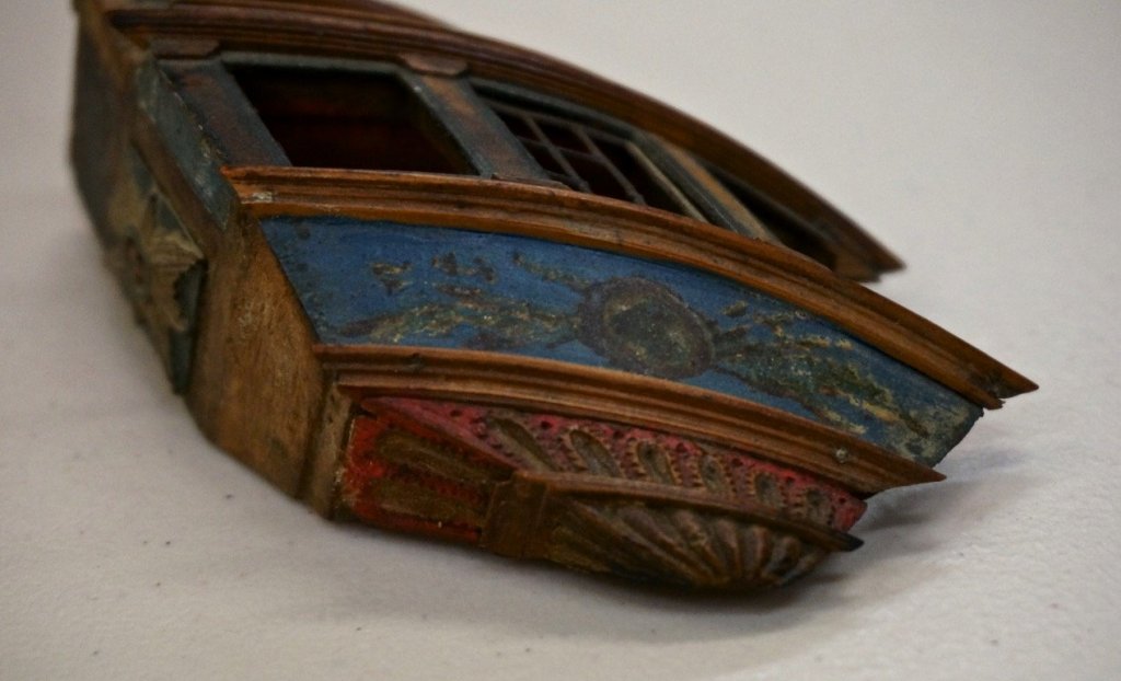
Here you could see the outside of the ship and where the stools should be.
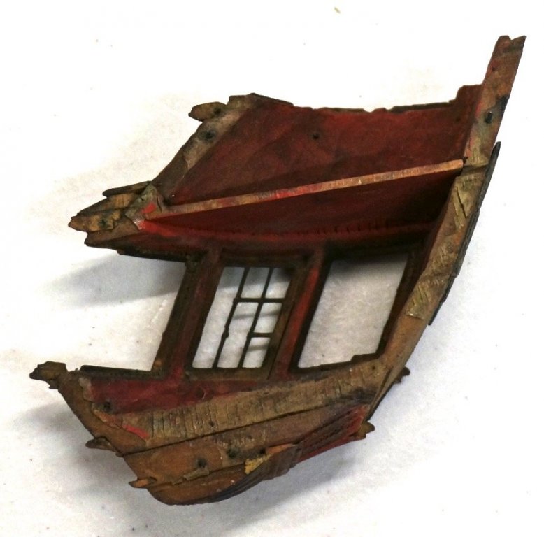
And so it looks complete. Opposite you see the entrances to the side galleries and the direction of the decks.
-
Hello Mark,
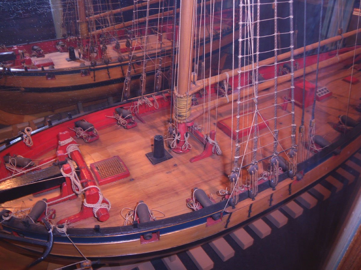
did you see the pictures of the cutter Cheerful from the Rogers Collection? Even at this cutter from 1805 the breech ropes where laid only above the cascable and not turned around it. It seems that the gunners at that time did't fear that it would slip down.

At least it looked like on a bazaar, everyone who had a picture with a cannon on it, posted it. But none has any historical sources for that!
So I think we are right to do it like the historical sources, Falconer, the Royal George and also the Cheerful model show it.
Your cannons looking pretty good. Greater pictures would show that much better 😉
- paulsutcliffe and mtaylor
-
2
-
Hello Jan,
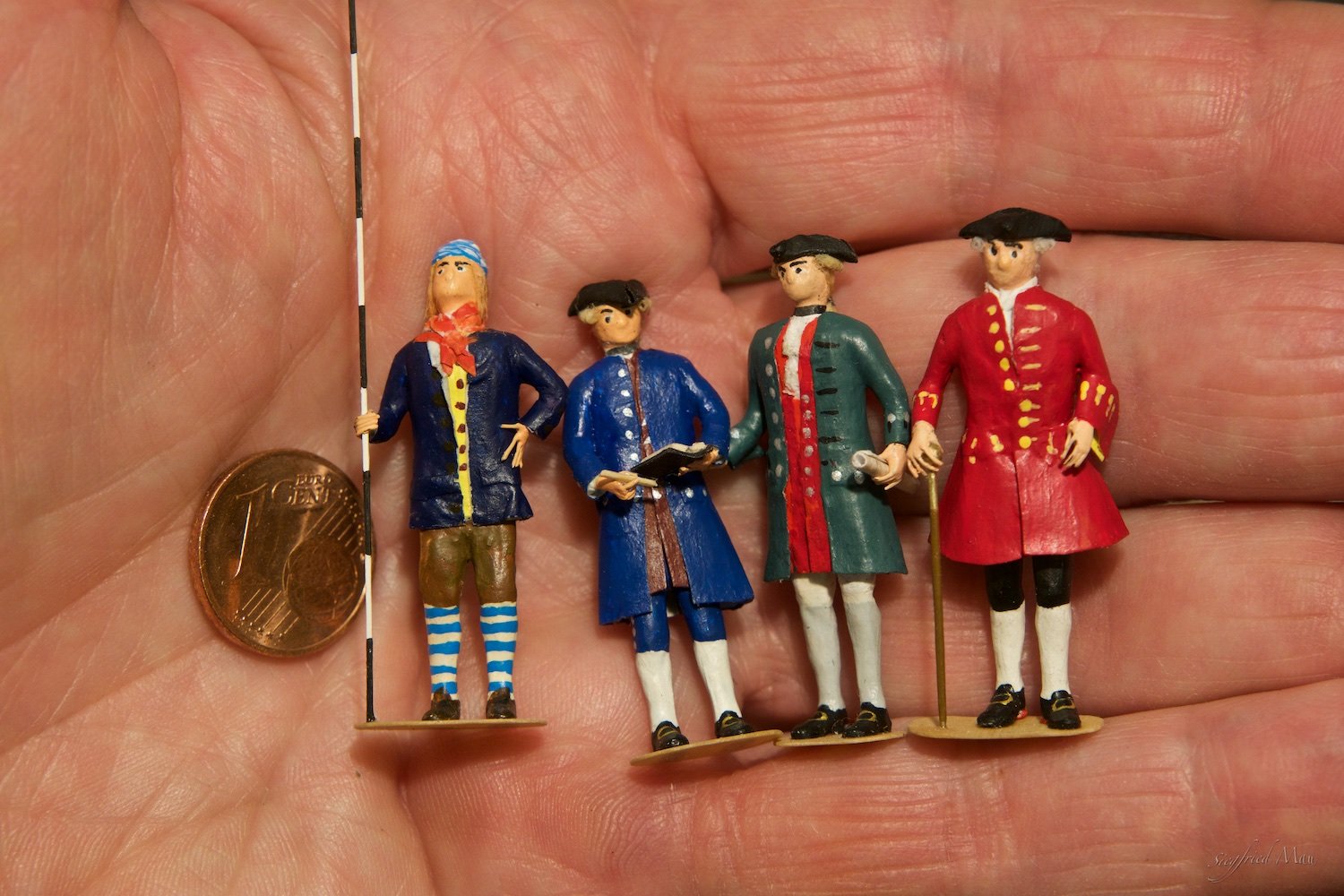
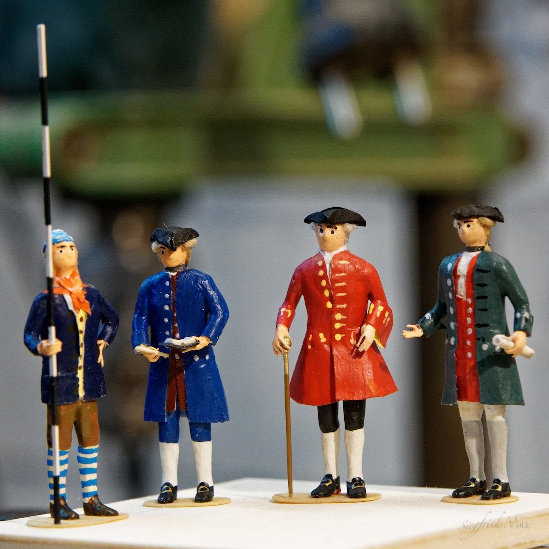
I think you mean how I managed it? The short version is, with much patience and and strong glasses.
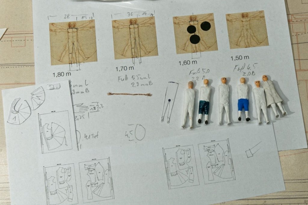
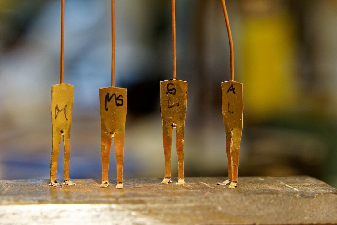
The long version is trying and trying. I think it's the 4. generation you see there. Here some pictures who may explain more then words.


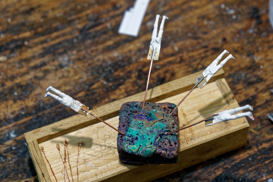
And that are the guys who did't make it and now had to suffer for some experiments
-
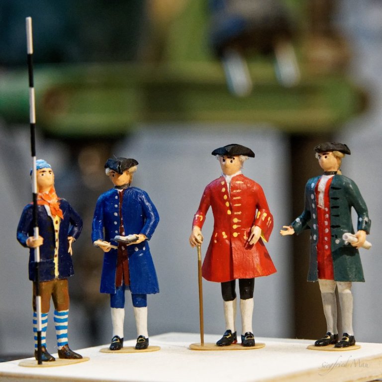
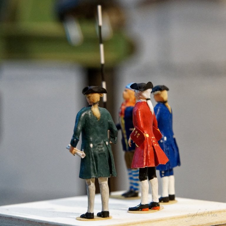
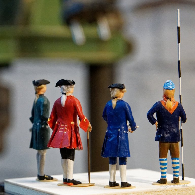
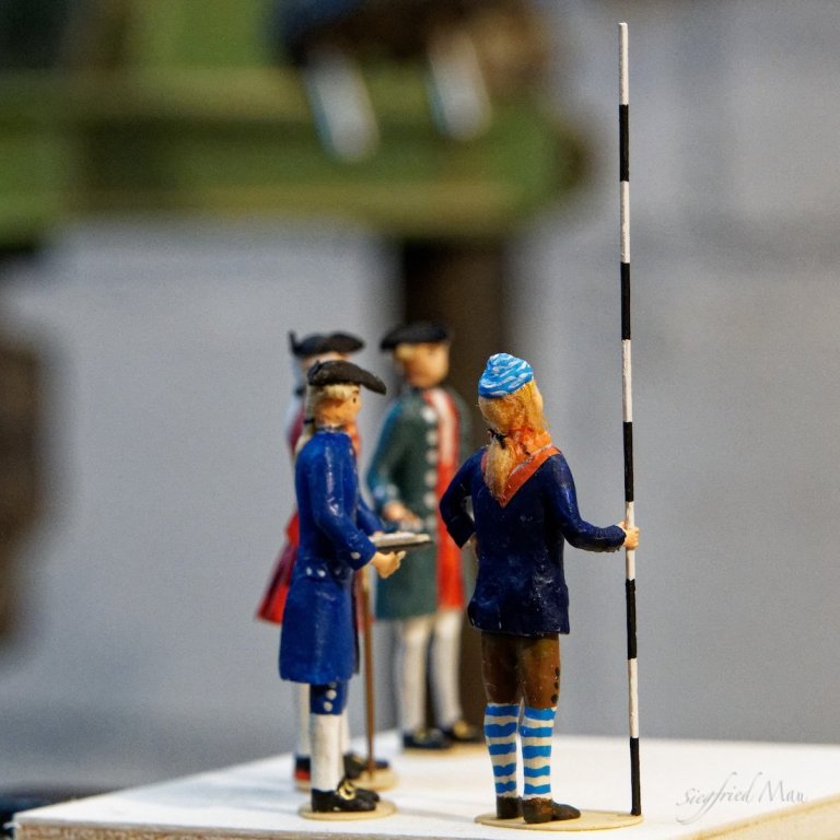
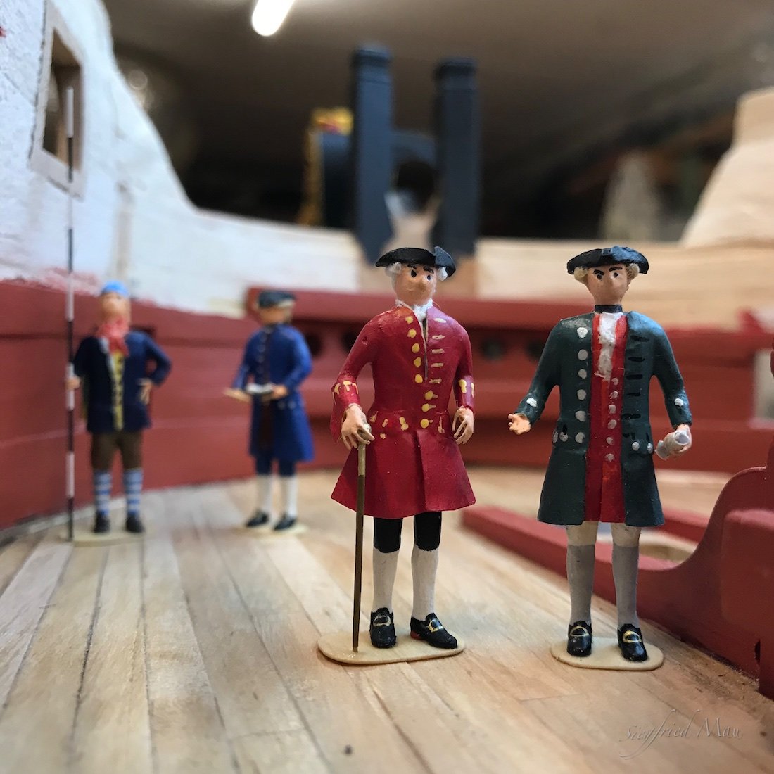
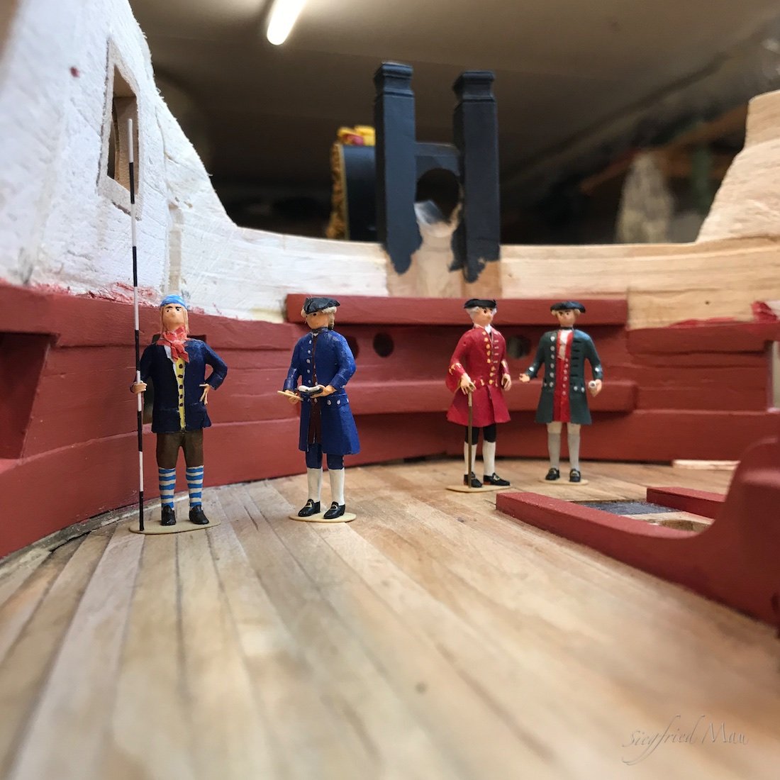
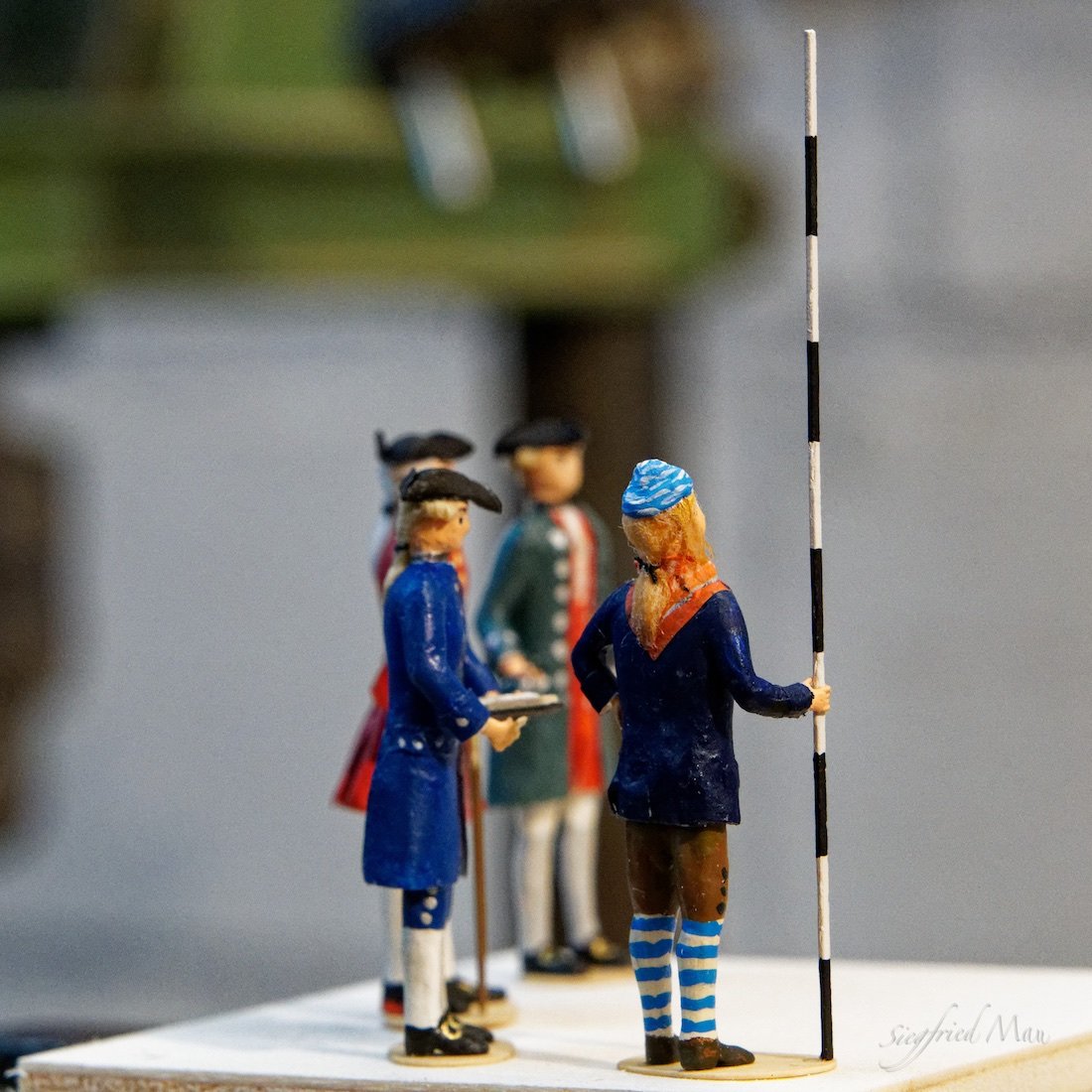
Hello,
today we had an inspection from the admiralty. That is the guy with the red coat. The shipwright try to explain, why the shipyard is't working at all: because the main worker did't feel very good. But he should soon start working again.
In the background his assistant controlled the high of the deck clamp. It's pretty low. Here you could stay only between the beams!

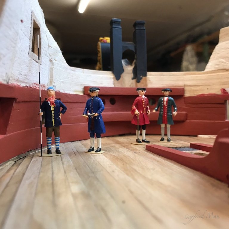
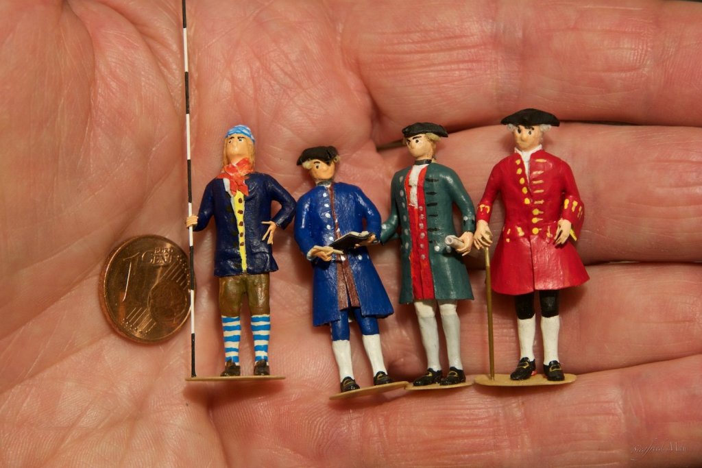
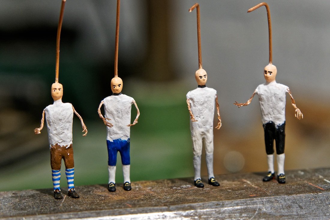
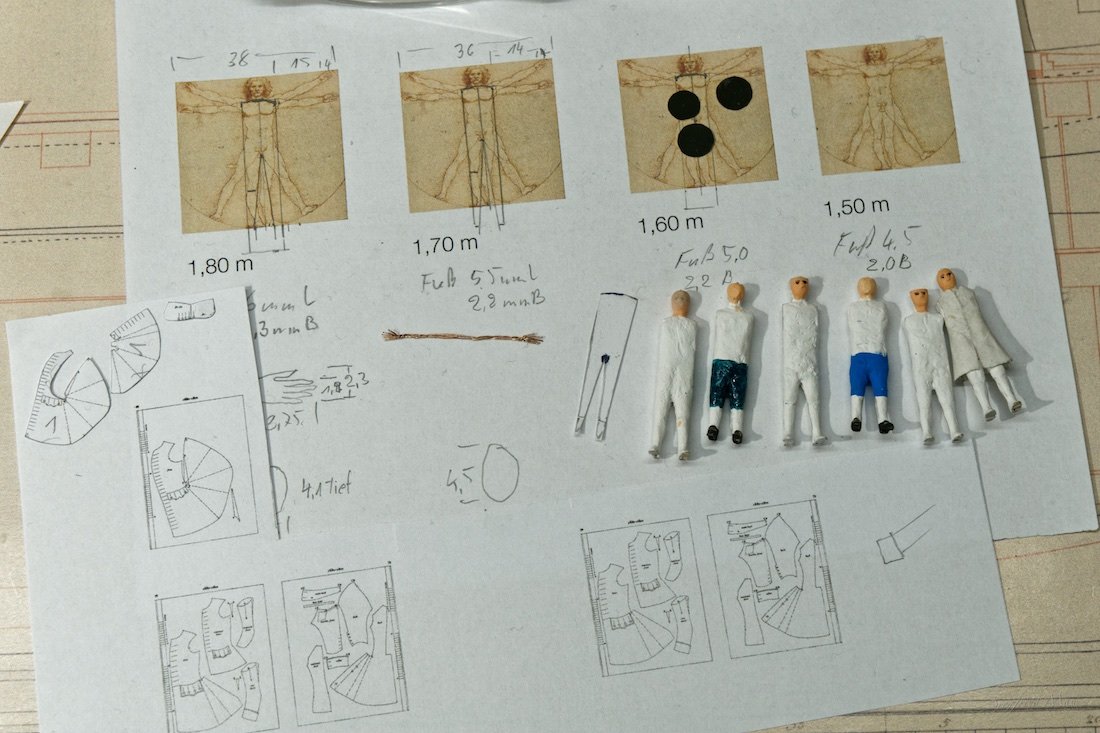
And here is the new crew. I build them from sheets of brass, wire, plaster , paper and cotton for hair. And of coarse a lot of paint. And yes, these clumsy hands could build such small and delicate things. 😉 But it was't easy.
I feel a little better now and hope that I could start working again soon. My main problem is that I'm so spiritless, and the next time I have to build the gun ports for the upper decks. That is nothing that really encourage you.
- FriedClams, Jack H, Mirabell61 and 13 others
-
16
-
Hello Mark,
I think, you think all too complicated. There is a gun crew, and I think that there are one or two members who have the duty to look after the breech rope. And if there would be any problems, they would have changed that system.
Then the breech rope is quite heavy, so I think that they will not move so easily then the ropes we use in our models. 😕
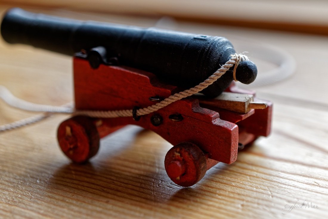
An last, as I wrote before above, that there may be a small rope (or something smaller than that, I have at the moment no name for it) to size the breech rope at the cascable. For a better understanding I made a picture.
- GrandpaPhil and mtaylor
-
2
-
Dear Druxey,
starts now the same procedure as with the paneling of the outer walls? There also all pictures, paintings and sketches I posted where in your eyes fantasy, artistic freedom or you could’t see anything. But at least it turned out, that I was right.
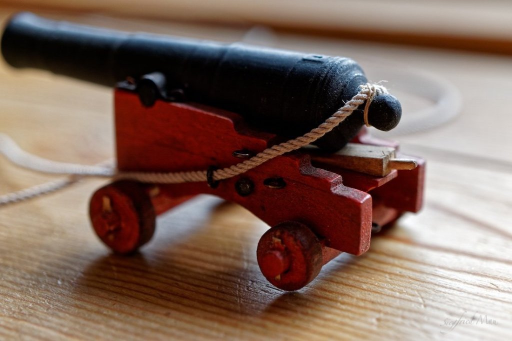
So why are the outer circumstances, the color, the wheels and the cannons now are an argument that all the rest is not true? That model is from 1756, may be a little fancier then an original ship. We don’t know what the artist would show us with this model. The white wash came later and also red wheels on cannons made the floor colourful, not only black one. But they are ok. I never heard something against that. At the Victory these wheels where not painted.
We agree with the fastening of the breech rope to the rings bolds at the walls. So it’s also at the Victory. I think Falconer did’t show that knot, because it did’t matter. Every man knows, that there has to be a knot. And he shows clearly, that the rope is only laid over the cascable. And that you could all see at that model, so why it’s not useful?
I thought that we are here in this forum to share wisdom to build better models. But if it’s not liked to have an other view, or find something out, I let it. I have nobody to ask how I build my ship, and at least it’s not important for me, how other build theirs. So many build there ships in Hahn style and others in druxey style. I was really shocked to see the double curve you build in your wales. Did you never noticed that you are the only one who build it so? And the port lids, only two models I found have that step around the lid! But nobody noticed that before! And nobody, except mtaylor, liked it. Thank you for that Mark.
Druxey, I liked the support I got from you over the time. But you should also be more open for others, who found out something different, or noticed something you have overseen.
-
Hello Druxey,
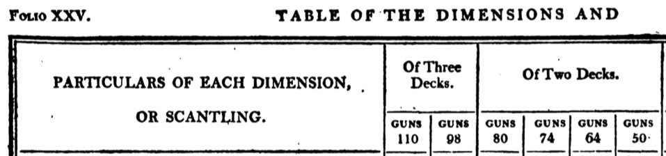
may be the black rim at the wheels are only black paint. The guns at the GD where 42 pdrs and at the MD where 24 pdrs according to R. Winfield's British Warships in the Age of Sail 1714-1792. They have at the breech nearly the same size. The NMM write, that the model was made 1756 and ok, the color. You like more white ships, without much color. But the ships in those days where colourful. And this was a 1. rate!
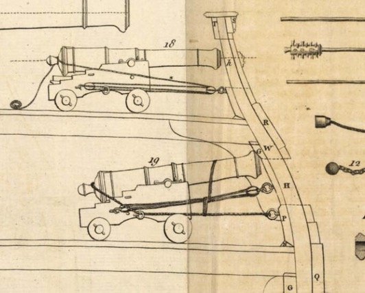
Please have also a look at Falconer's cross section of a 74 gunner, there you see the same thing.
-
Hello Mark,
with that what I know is Druxey right. Then you could shorten the ropes easily to store the guns during voyages, or move the guns. A good example is the model of the Royal George (1756) https://collections.rmg.co.uk/collections/objects/66456.html at the NMM. Here a screen shot
And there is no turn of the rope around the cascable. I don't know where, but I remember a picture where the breach rope was sized there with a small rope around the cascable.
I hope I could help.
-
Hello Doris,
your work is unbelievable. The yacht and the the crew!
That reminds me of this page: https://rococoenminiature.heidecksburg.de/pages/die-ausstellung/shop.php#oben Sorry, only in German and with Flash Player. I have none!
I saw a film about this in TV, they have the DVD in the shop. There they show also how they build it, back in the ex DDR. I plan a visit there this year. I forget to mention, it's all in 1:50!
-
Hello,
thank you all for your comments and likes.
Mark, I don't know if they also used leather for caulking. But old ropes I think they had plenty.
Dowmer, »that gunport practice was only one way« of course there are different forms of gun ports, but for my ship there is only the standard form important.
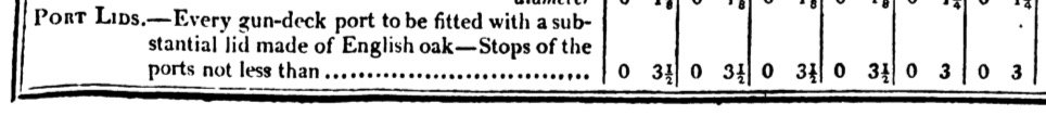
When I'm seriously look at the Bellona pictures, I could't see what you see. Even if I want to see there something. The outer planking of the lid should be of the thickness of the outer planking of the ship. That said Goodwin and Mark P confirmed that. Even when his contracts are from the 1690th. That may have changed with the time. But you could't tell it from these pictures.
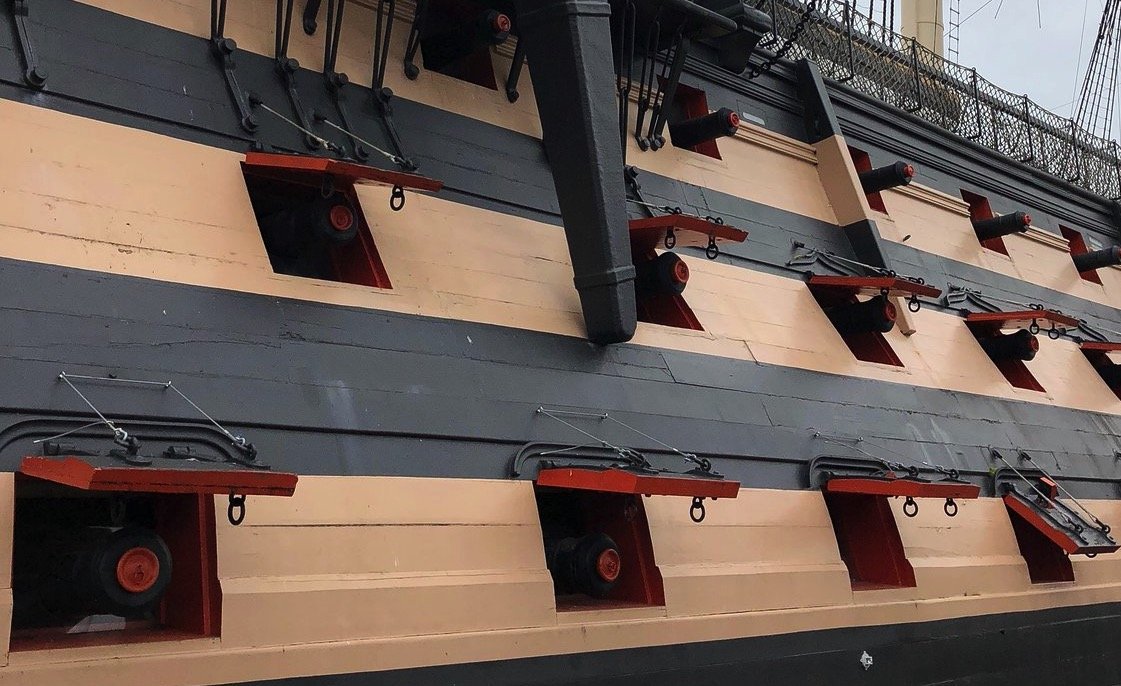
The pictures from the Constitution are from an other time and the port lids seem to be much thinner. Like these from the Victory, after all the repairs. May be they are at that time always thinner, as Steel stated. And if there are an extra sill, I cant see it. I see there only the stop, normally build by the frames. But only to the sides, not at the bottom. But may be you have there more insider knowledge. But as Mark P said, linings where not build.
So, for now we have cleared these facts. The port lids have no steps to there sides, even in later times. The outer layer are of the thickness of the planking of the ship at this place, with a lining of elm 1-1,5" thick. That says, there must be cut an extra rabbet. When in later years the port lids get thinner these extra cut rabbet disappear.
Not clear is, how that was in 1745. The list of establishment deals only with the main structure, keel frames and so on. So all other things they took I think from the 1719 list of establishment. Ok, they did't mention there port lids. So we did't know if they are getting already thinner at this time, or in 1745.
-
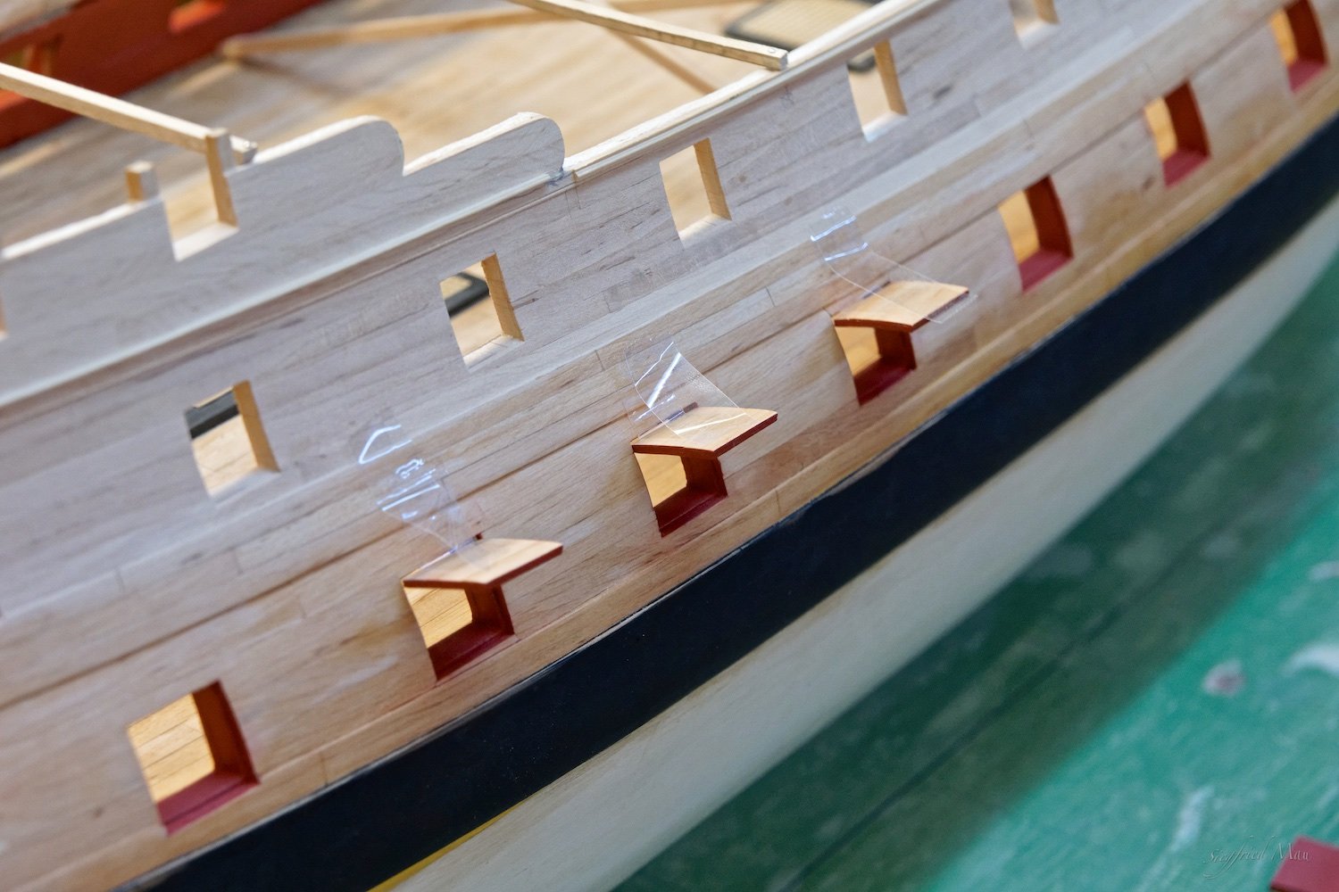
Just an update with pictures, from the framed Bellona. That did't look like a shortcut.
- mtaylor, scrubbyj427 and popash42
-
3
-
Hello Marc,
that sounds all very logical. But do you think that all modellers of that time make the same shortcut? And also the painters? I did one side of the ship this way, it's more complicated then making the lid with a step. I think that it's a shortcut of modern modellers. Also when that exist already in earlier times.
As I once before tried to say, the lids of the contemporary models seams to have the right thickness. Outer planking the same size then the ships planking with a 1-1,5" lining. So they had to cut back the frames a little. And the rabbet is much les then 3-3,5"= 1,6-1,8 mm broad. May be 0,5mm =1" This 1" or a little more and another 1-1,5" deep, that would be the rabbet I'm speaking about. And it's above the gun deck, so the ship would't fall apart from this.
On the other hand, who told us, that the outer planking of the lid is of the same thickness then the outer planking of the ship? I found that in Goodwin's book, but what is the source? I cant remember. What is, when the whole lid is between 3-3,5" thick? The magical number from Steel around 1800! Then Victory's Lids are of the same thickness then the planking of the ships side (it looks so), then no extra rabbet is to cut. If that is also true for the older ships, I don't know. As I said before, they look at the models as if they have the right thickness.
One argument we did't discus till now is the fact, that if the inner lining of the lid has the same size of the the outer planking, all for sides of the lid lie in the rabbet. Not only the left and right side and the plank above and below, when the lining is cut back. I think the construction is weaker when the lining is only nailed to the back of the outer planking.
Druxey, that are your strong arguments? You could put these two sentence in a grinder, there would't come out more.
For those who did't know what we are speaking about, that is all from a book of 641 pages! At least it mean, the lid is not less then 3-3,5" thick
- FriedClams, mtaylor and paulsutcliffe
-
3
-
Hello Mark,
yes I know, but it's the only ship where you could see it today. Yesterday I searched for the Tricomarlee and Unikorn, but it looks like they did't have port lids. The Tricomarlee has one port closed, so you could see nothing and the other ports lids are not there.
A happy new year to you
-
Hello Karl,
the ports where caulked with oakum and fat
- mtaylor, cog and Mirabell61
-
3
-
Good morning,
now we are there, where we where before this discussion and as we ever build our models. The only difference is, that to the top of the lid is no stop anymore. You would't find also any model with such a broad rabbet. When yes, they must have the same thickness as most lids, but mostly they are much thinner. I think it's a shortcut as I stated before and most of the contemporary models say I'm right. Why did you ignore that? I mean the contemporary models.
Dowmer, why do you think that they did't rabbet into the frames?
Goodwin says in his text: that the outer planking of the lid is equal to the thickness of the ships side planking and Y says: variable according to the thickness of the ships side planking. That doset mean automatically, that they are together have the thickness of the outer planking.
»None that I can find, show the lid rabbet “let into the ship frame” to make up for the thickness of the lining.«
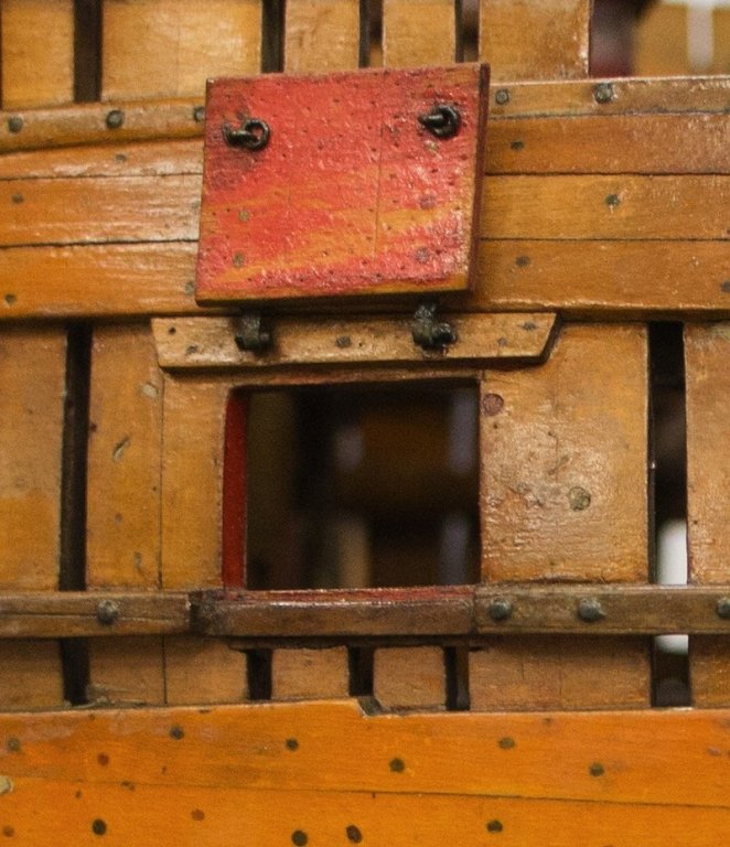
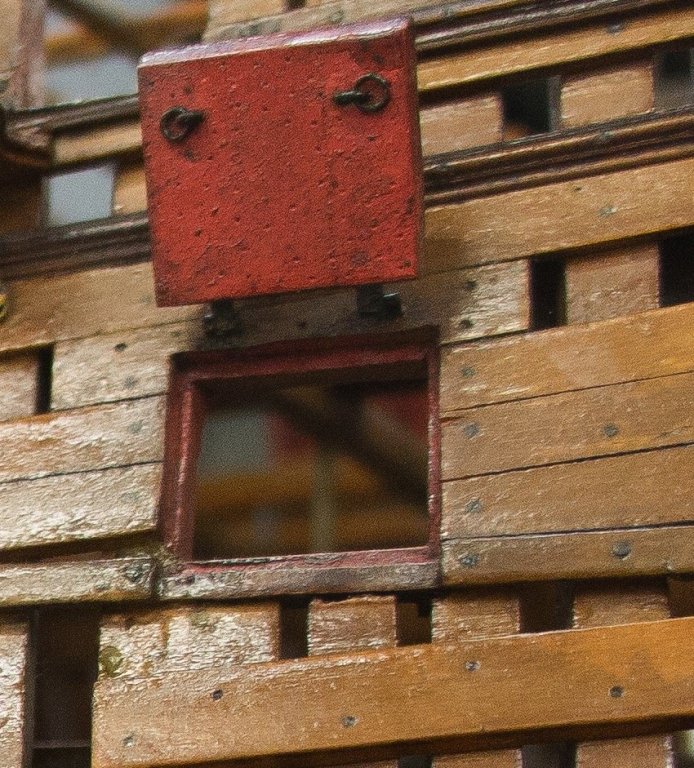
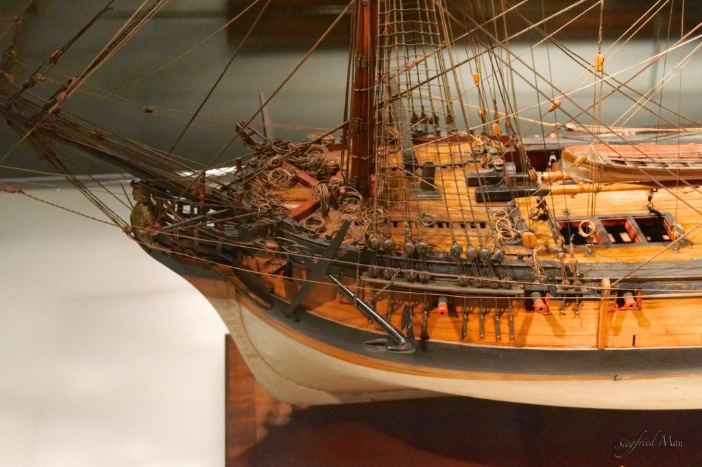
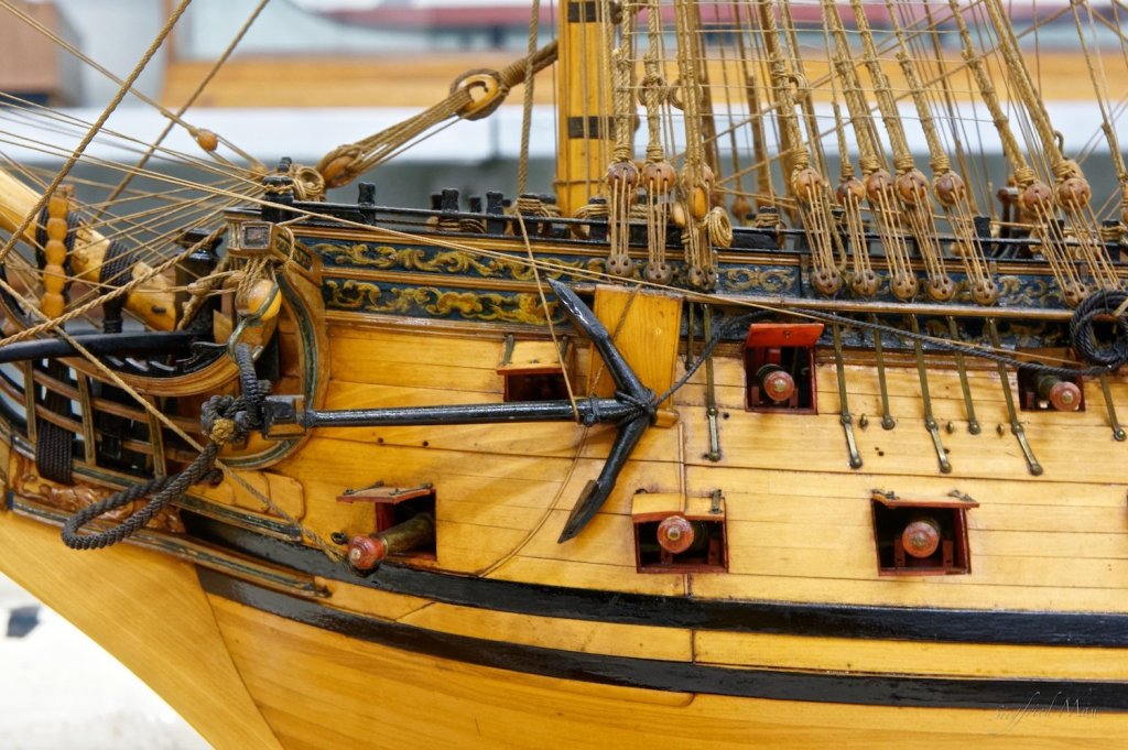
You could see the rabbet all around the port hole on contemporary models. How deep they are you could't see. But deep enough for the lid and that means they have to cut the frames. There are to my knowledge only two models that show a rabbeted lid as Druxey and Mark P will shows us. All other models show lids as the Victory has. Here an other picture of the Victory where you could see the rabbet better. But not at the bottom of the port hole! These port lids seems to me have the thickness of the outer planking of the ship. In this case you haven't to rabbet the frames.

-
-
Hello Johann,
your ropes looking great, especially the silk ropes. I burned my linen ropes to eliminate the fine hairs.
Should your Creole look afterwards also like this model? The captain must have been on vacation!
-
Hello,
no, you did't take my threat over. I started the discussion and thought that we could settle this may be for all.
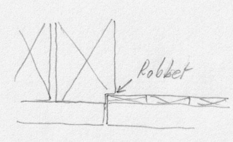
What makes me a little curios is the fact, that most, when not all, admiralty models have these square ports, without any step. So as I drew it at the right side of my drawing. I think that this is not only a shortcut, they are nearly in the accurate size. To understand what I mean, my planks at the gun deck are 3" thick and have a lining of 1" = 1,6 mm + 0,5 mm = 2,1 mm


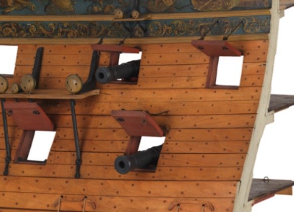
Here the Centurion 1:48

and the 60 gunner 1:60. Here the ports are slightly thinner.
You could see, that the dimensions are nearly the same. They did't skip the lining.
There is not much written about the port lids. Goodwin wrote that they are without a step around them and the Victory has that future. Lavery mention them, but did't write nothing special, because he had no information I think. And there is that one sentence in Steels treatise from around 1800 that is now the truth.
I would no one irritate, but we should together find an answer and the models speak for themselves. The shipwrights know what to do. That is with most things of the past the case, where every body know how it looks like.
Druxey, could't it be that you misinterpret the sentence: Well seasoned linings fitted into the stops. That could mean all, even that:
And most models give me right. Ok, you have to rewrite some of your books, that is the bad thing about it and I'm not lucky about it. You remember the wales. You could interpret it your way, but all the models show it the other way. So what is right?
- Mike Y, mtaylor, scrubbyj427 and 1 other
-
4
-
-
Doris, that is unbelievable.
By the way, my car needs also some renovation 😙
- EJ_L, popeye the sailor, BETAQDAVE and 3 others
-
6
-
Hello,
many thanks for your comments and likes.
Druxey, now I found it too. That looks as if you are right, but why did't have the Victory that? May be that changed from time to time.
Mark, thank you for your efforts. When I understand what you have written, then you mean the rabbet in the port. That is not the question. I asked me, and you, if the lid has a step, that fits into this rabbet.
The left drawing shows what Druxey says and the right drawing what I understand, seeing all the contemporary models and also the Victory, with no step at the lid.
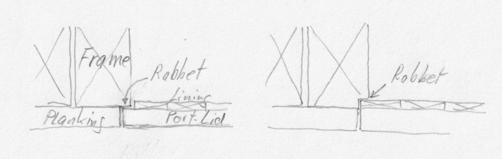
I found one other model then the Bellona (below) who has that step.
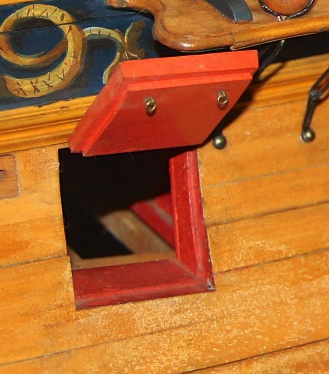
It's probably the frigate Lowestoft SLR 0339, a model from about 1761.
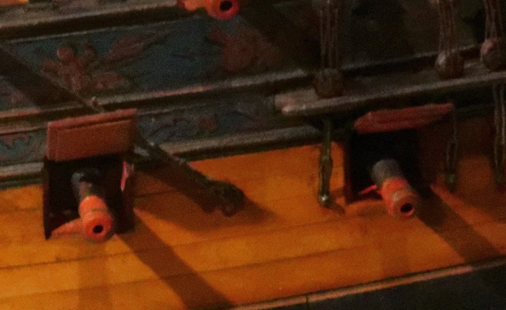
But even the large model of the cannon decks from the Royal George did't have it.
May be its only a shortcut from the modellers not to show the lining. But at the other hand, I could argue it's a shortcut of the modellers today not have the lining the same wide as the lid. Then also the lining would lie at the rabbet and add strength to the lid. Not for stopping cannon balls, but the sea to come in.
I build my ship now as I started and because most models look so, I think that it might be right.


HMS Bellona 1760 by SJSoane - Scale 1:64 - English 74-gun - as designed
in - Build logs for subjects built 1751 - 1800
Posted
Hello Mark,
these knees at the gun deck where the worst knees ever! Because they are so deep down in the hull. I'm still not sure, if I build them in the Tiger.
If you wont to see the plan of the Berwick as a whole: https://collections.rmg.co.uk/collections/objects/370801.html
That plan helped me a lot. And here some impressions when they are ready installed.