Louie da fly
-
Posts
7,990 -
Joined
-
Last visited
Content Type
Profiles
Forums
Gallery
Events
Everything posted by Louie da fly
-
 I like the look. Am I right in thinking he's wearing ankle boots and leg wrappings (known to the Vikings as wickelbander and to the English as winningas)? If so can I suggest making the boots and the leg wraps different colours so you can tell which is which? Although modern re-enactors usually make wickelbander out of strips cut from a piece of fabric, back in the day they were woven (from wool) as narrow strips. One other comment - as someone rich enough to have a sword and helmet he looks a little scruffy. The Vikings were great show-offs and would flaunt it if they had it. So I think the helmet, for example, would be shiny silver rather than blackish or rusty. Maybe he's been living a hard life recently. And perhaps a design on the shield? (see http://members.ozemail.com.au/~chrisandpeter/shield/shield.html for some info on that). (well, you did ask . . . )
 -
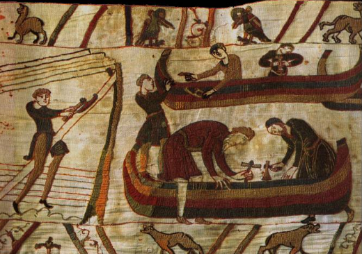
Yep. It's even shown on the "shipbuilding" panel of the Bayeux Tapestry, where a fleet is being built for William of Normandy to invade England. (Also a hand drill held by the guy on the right working on the upper ship, and perhaps a smaller one held by the left-hand guy on the lower ship)
-
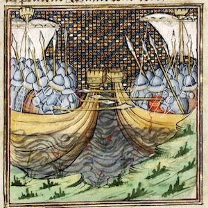
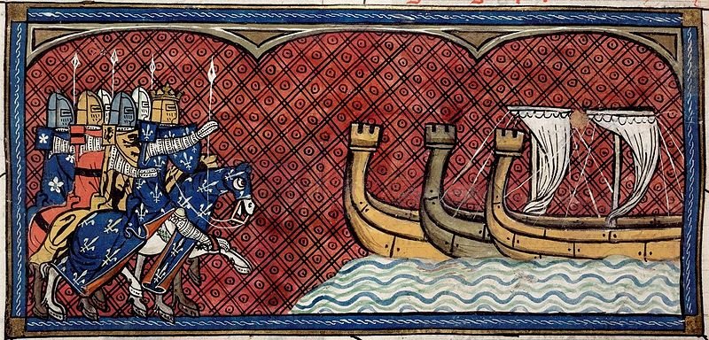
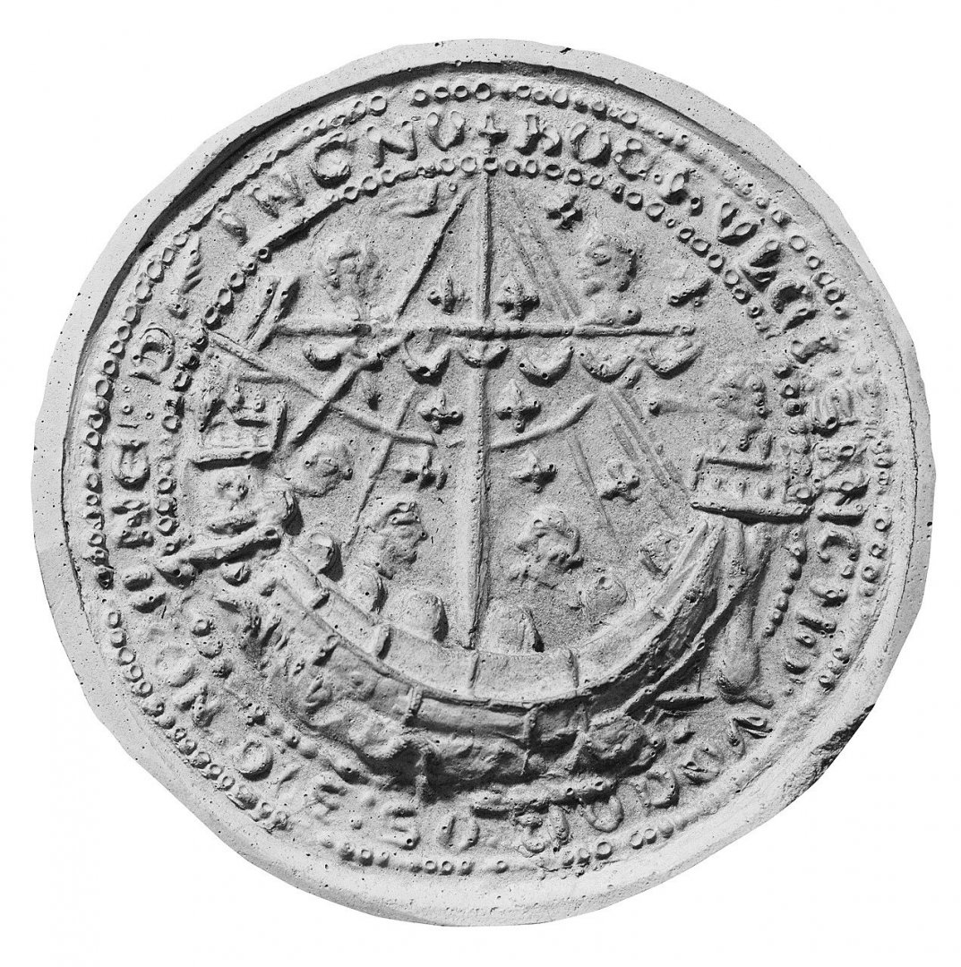
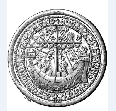
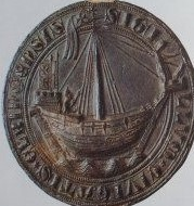
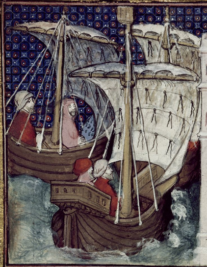
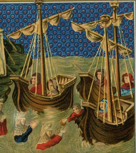
That's possible, but we need to remember that the northern Europeans had sailing ships well before the crusades (at least as early as the first Viking raid of 793 AD and probably earlier) and so would already have evolved their own means of belaying shrouds. Though it's quite possible that Mediterranean ships influenced those of northern/western Europe, the influence also worked the other way around, with single-masted square-rigged vessels similar to cogs suddenly appearing in the Mediterranean after centuries of multi-masted lateeners. As far as shroud fixings go, we're probably best relying on the existing evidence - which unfortunately seems to consist only of pictures produced by people who may or may not have been familiar with ships - but that's all we have. Regarding the nature of a hulk - the current theory amongst academics is that unlike "nefs" (still not an official term, but it serves for the time being) which have a stem and sternpost and have conventional clinker planking a hulc/holk/hulk is characterised by two design features - "reverse"clinker planking (with the overlap upwards rather than downwards) and a lack of stem and sternposts, with the planking doing all the structural work and somehow curving around the bow and stern. Apparently some small river craft have been found built this way. What set this all off was the 1295 AD seal of the town of New Shoreham, (previously known as Hulkesmouthe) which has an inscription referring to the ship on the seal as a "hulc". Here are two photos of the seal: And a 19th century (I think) engraving of it which gives clearer detail, but may incorporate copying errors. Ok, there are no stem or sternposts shown,but there's no sign of reverse clinker (in fact the lines between the planks are raised, not recessed and the planks all seem to be in the same flat plane). For reverse clinker you need to go to the pictures below. BNF Psalter of Jean de Berry Gallica f.127r Philippe_Augustus awaits his fleet So the shading certainly seems to suggest that the lower planks overlap the upper ones. But is that enough to base such a complex, unwieldy, top-heavy theory on? Perhaps it's just artistic error on the part of someone who'd never looked closely at a ship? Ok they've found some small river vessels built that way but would a large ship of that construction even be seaworthy? And (Occam's razor) why would anybody build it that way when standard construction is so much easier? And that the New Shoreham seal calls the ship a hulc is a pretty thin bit of evidence that the word describes that specific type of ship. Maybe, like "nao", it just means "ship", or perhaps "cargo ship", or "warship" or . . . It seems to me this theory is like a house of cards - one touch and it'll all come crashing down. Or maybe the Emperor's New Clothes would be a better comparison. Sorry about the rant, but this has become the "standard" idea of what a hulk was, repeated in any number of academic papers and I believe it's one of the worst examples of academics quoting each other as proof of a theory with almost no reliable basis in fact. Of course if some archaeologist does find one, it'll blow my objections out of the water. But I'll wait till then to change my opinions.
.thumb.jpg.bcb5cb61c4010e5145de6b5d02584e1d.jpg)
-
In many (not all) contemporary representations the forecastle is shown without a rear "wall", so access is pretty easy. But there are also quite a number that show it with a rear wall, so perhaps both are correct. However, getting into the forecastle on this kit does seem a little difficult. I don't know what the right answer is but you raise a good point, Chuck S.
- 179 replies
-
- 5
-

-
- shipyard
- wütender hund
- (and 1 more)
-
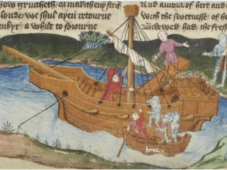
I think all ships with the classic cog shape (straight sternpost and usually - but not always - straight stempost, fairly integral sterncastle) have stern rudders. An interesting detail on the one below is the lashing around the stempost under the forecastle (which again is a polygon, not a rectangle). The ships on the Sandwich seal and in the photo I'd call nefs, for lack of a better name - I wouldn't call them cogs; they're more like Viking knarrs with castles.
-
Thanks, mate. Your choice for fixing the shrouds sounds like a good one. That Luttrell picture is certainly very good. I could only wish all the others were as good! I mostly get these pics by starting with Pinterest and when I get something I like I see if I can find the original website it was taken from - either from the Pinterest entry, or by doing a Google Image search or by pasting the name of the document (manuscript name and folio number if possible) into google search and see if anything comes up. It's surprising how often that's successful. And often one Pinterest image leads to another and another and another. . . .
-
This idea is dealt with briefly in a paper at https://www.academia.edu/5176098/Naval_warfare_in_Europe_c_1330_c_1680?email_work_card=view-paper which is mostly about the impact the development of guns and gunports had on maritime warfare, but includes the passage "As a sea-going ship could be easily transformed into a warship –by putting superstructures called ‘castles’ fore and aft(14) and, after the introduction of the heavy gun, by temporarily adding gun-ports and strengthening the hull and masts(15) – merchant fleets were of great military importance and crucial for the execution of sea power." Footnote 14 quotes T. J. Runyan, "Cogs, Caravels and Galleons". in The Sailing Ship 1000-1650 , by Robert Gardiner. - London (1994) (But I'm not prepared to pay US$38 (or $350 from Amazon) for a book to satisfy my curiosity as to what someone might have said about adding castles to merchant ships to convert them to warships. OTOH it looks like it might be interesting and they have a copy in the State Library of Victoria. Maybe I'll go and visit when the Covid thing has blown over). Backer said: "Where I live. We dig a big hole. And find... a cog" And that's only Doel No. 1! There's another cog - Doel No. 2! https://www.academia.edu/27506746/Doel_2_a_second_14th_century_cog_wrecked_in_den_Deurganck_Doel_Belgium It's hard to believe your model is made of card, not wood. It's very impressive. And now you're going to make the wooden one! Good stuff. I wonder whether the best translation of Wutender Hund into modern parlance wouldn't be "junkyard dog"?
- 130 replies
-
- 4
-
-
- wütender hund
- hanseatic
- (and 2 more)
-
I think both of these would work, and the idea of extending the knees upwards would certainly be feasible. But the horizontal cleat would be more secure. But have a look at my most recent posts in which deal with all the evidence I've been able to find for belaying points in ships of this period. It only deals with shrouds, but there's nothing at all for belaying points for any other ropes. And as far as I've been able find out, there haven't been any rigging items found at all from shipwrecks of this time period. If you do find any, I'd be very interested.
-
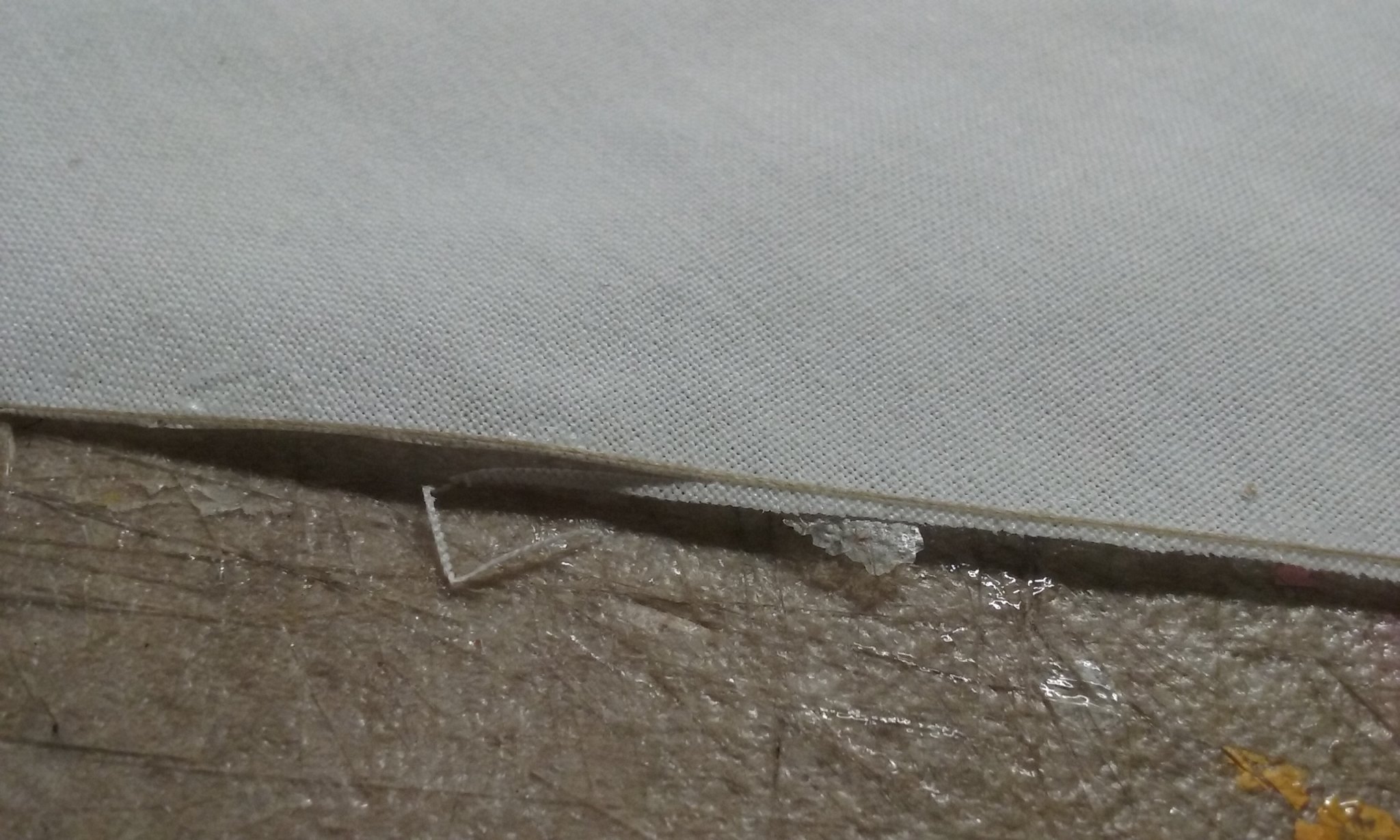
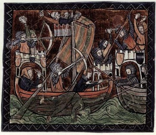
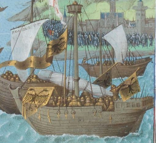
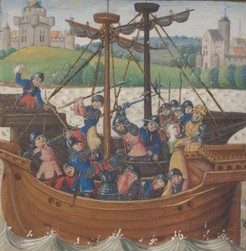
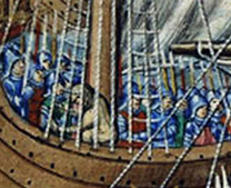
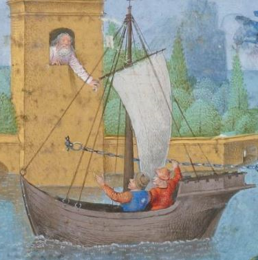
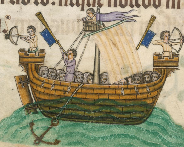
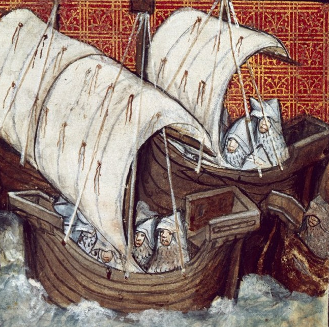
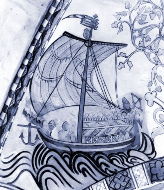
Chuck, the model I put up in post # 35 (with all those pictures of seals and manuscript illustrations) is of what I call a nef - there's really no accepted name for them - from the late 13th-early 14th century. (Nobody really knows what exactly a hulc/hulk was, and to be honest I think the currently accepted idea of its nature is based on such thin evidence that it should never have been entertained in the first place.) I wouldn't take too much notice of the configuration of the model's shrouds - it's a modern interpretation, after all. I'd be relying on the contemporary representations, though it has to be admitted they give very little detail. I've had a look at archaeological finds but as far as I can see no blocks etc have survived. Naturally enough these are usually the first things to disappear as the upper works get eroded away, unless they fall off and are buried under silt and are thus preserved. However, my understanding is that hearts go back a very long way - certainly prior to deadeyes, which don't seem to have come in until at least the middle of the 15th century. At the risk of derailing the thread (though I think this information is actually relevant not only to your question but to this and other threads for 13th-15th century ships) the above illustrations and the ones I've added below are all the evidence I've been able to find for rigging items for ships of this period. Note the last one is very clear (it's from the Luttrell Psalter of 1325-40) and perhaps this is the best option for shroud fixings. My reading of the picture is that the shroud passes through a hole in the planking and is wrapped around a toggle. The red seal might be done the same way, and the two seals nearest the end (which I believe to be different impressions of the same seal) seem to have a similar system, but all the toggles are attached to the same horizontal bar. The one with the two-headed eagle banner seems to have the shrouds ending in eye-splices passing through metal brackets, on the far right of the second line it looks like the shroud passes through a hole in the bulwark and then is spliced back onto itself. Some shrouds end in unidentified "blobs" on the outside of the hull. The first three in post #35 above and perhaps even the seal of Dover in post #34 seem to have them terminate in ringbolts or eyebolts, as does the third one in the third line below (though that one has them sticking up from the bulwark whereas in all the others the ringbolts are on the sides of the ship). BNF Francais 64 f. 271r Harley MS 1319 f. 18 (1401-2) Harley MS 1319 f. 14v (1401-2) Rylands MS English 1, fol. 9v. (1401-1420) BM 1978,U.2028 Richard II's campaign in Ireland BNF Valère Maxime, Dits et faits mémorables f. 59v (1450-75) Early 15th century Seal of Southampton unknown, early 15th century BNF Français 64 Folio 333r (1401-1500) Seal of Elbing, Germany Luttrell Psalter BL Add MS 42130 f. 161v. of 1325-40 These are all the contemporary representations I've been able to find that show the fixing of the shrouds, but it has to be kept in mind that many representations just show the shrouds vanishing behind the bulwarks, and thus presumably fixed somehow to the inside of the ship. I hope this is of help to you and to anyone else interested in this kind of thing (including, of course, you, PhilB).

-
Beautiful work. That's looking really good. I like your carpenter standing there ready to trim off the treenails with his axe . . . Maybe think about where your belaying points are going to be - where all the ropes get tied down to. I didn't think about it with my own build and now I'm having to get clever figuring out where to put cleats etc after all the main structure has been finalised. I love your planking, by the way.
-
That certainly looks better. I would go so far as to cut the stem and stern posts off just below the decks of the castles. It seems to me that firstly there's no structural reason to extend them past that, and secondly they'd get in the way of the people on the deck. What you might also like to do is have a forecastle which is rectangular but with a sharp end as in the pics below - this seems to have been a fairly common feature, and would give more room on the deck without interfering too much with the balance of the ship. Note also the supporting brackets below the castles and that the stem and sternposts don't protrude above deck level.
-
Oh, for a moment I thought you meant there were going to be twenty-two more boats. I really should read things more carefully . . .
-
Beautiful work, Anthony. A magnificent model. Sounds like a good idea - assuming you are prepared to put the extra work in . . .
-
Nice work. That pulley system is basially the same as I'm using on my dromon, though the details are a little different. Where did you get the sheaves (wheels)?
-
The Mighty Hood. What a classic ship. At 1:200 she's going to be pretty big, isn't she?
-
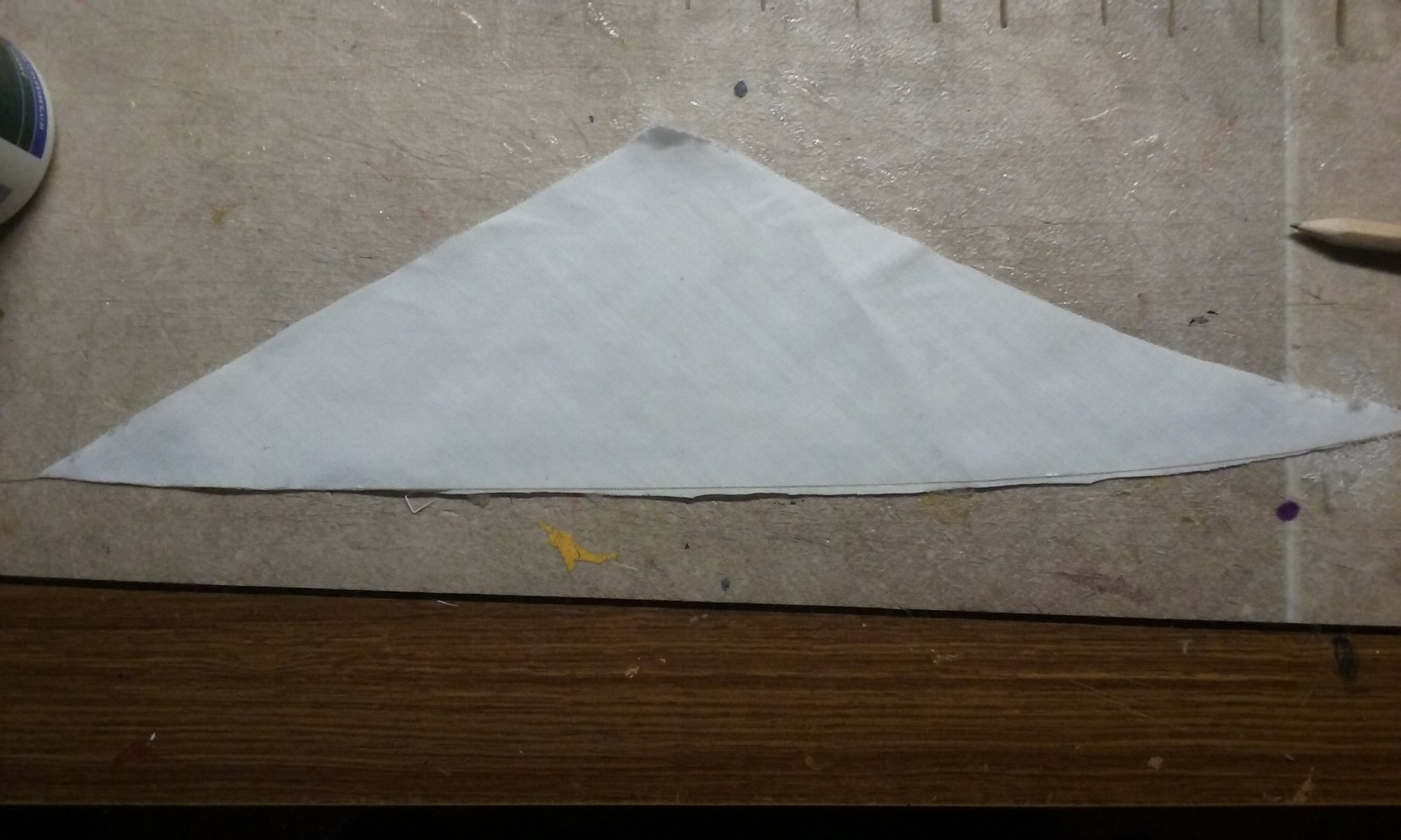
Yep, guesswork. I started out with a 90-45-45 degree triangle, with the long side running along the yard. Then I made the distance between the side that runs along the yard, and the vertex oposite it, half what it would otherwise have been. No idea if it's going to work, but if not I'll just have to cut some more off I suppose.
-
Welcome to MSW, Clark. You'll find there are several other MSW members have built or are building Amati's Coca - you can find them by typing Amati Coca in the search bar at the top. You might find that they'll help you with your own build. Problems you encounter in your build may already have been solved by these modellers. And there's a wealth of information and advice available from the friendly members here. Make sure you start a build log - instructions on doing that are here. As a mediaeval/renaissance freak myself, I'm looking forward to seeing your progress!
-
Welcome to MSW! With that number of builds under your belt, you must have amassed quite an impressive skill base. Make sure you start a build log so we can all enjoy following your progress (and offer help and encouragement as needed).
-
Not new to modeling, but new here
Louie da fly replied to gregdam's topic in New member Introductions
That's looking very good, Greg. Welcome to MSW. I'm another one looking forward to seeing the build log -
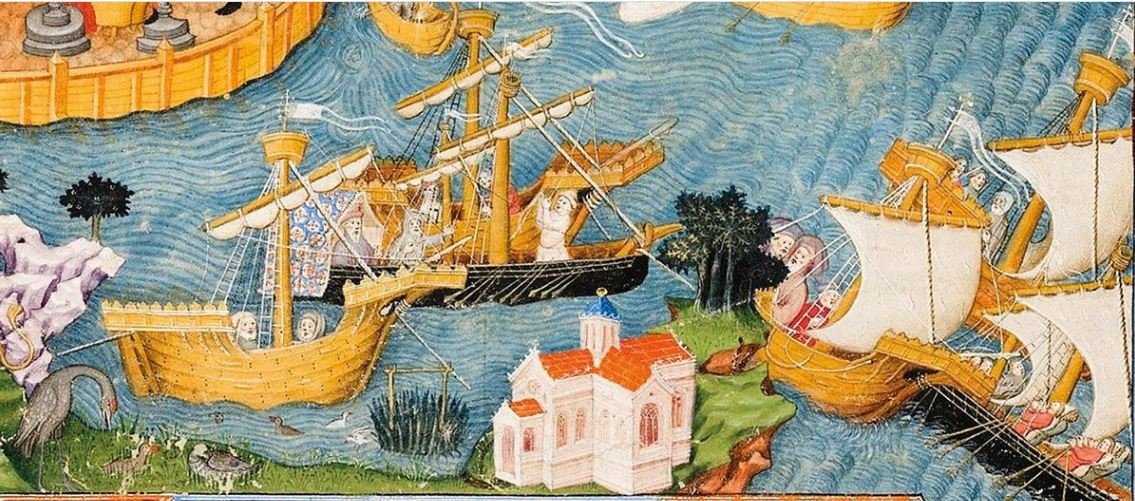
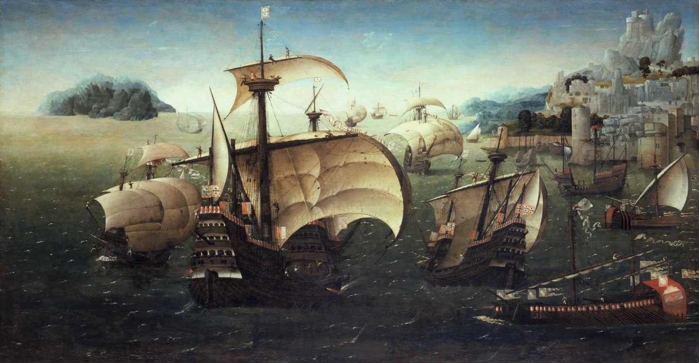
Nice looking model, and the idea of giving it new yards and fabric sails is a good one - I think it would add significantly to the presentation. This model is almost certainly based on the ship which appears repeatedly (in different sizes) in the painting below - and that is generally thought to be the Santa Caterina do Monto Sinai (launched in 1520, and da Gama's flagship on his third voyage to India). If that's the case the kit seems to have taken a few liberties with the colour scheme - more appropriate to the end of the 16th century than the beginning (but much more colourful!). I've always loved this ship and it's been a long term goal of mine to build a model of it. I didn't know there was a plastic kit available and though I no longer build in plastic, I'm looking forward to following your build. Carracks are a particular interest of mine and I've amassed a whole lot of information on them. If there's any way I can help with references, contemporary pictures etc I'd be glad to do so. I've put together a Pinterest page on larger, later carracks (which I like to call Great Carracks) at https://www.pinterest.com.au/lowe1847/great-carracksnaos/ which you might find of use.
-
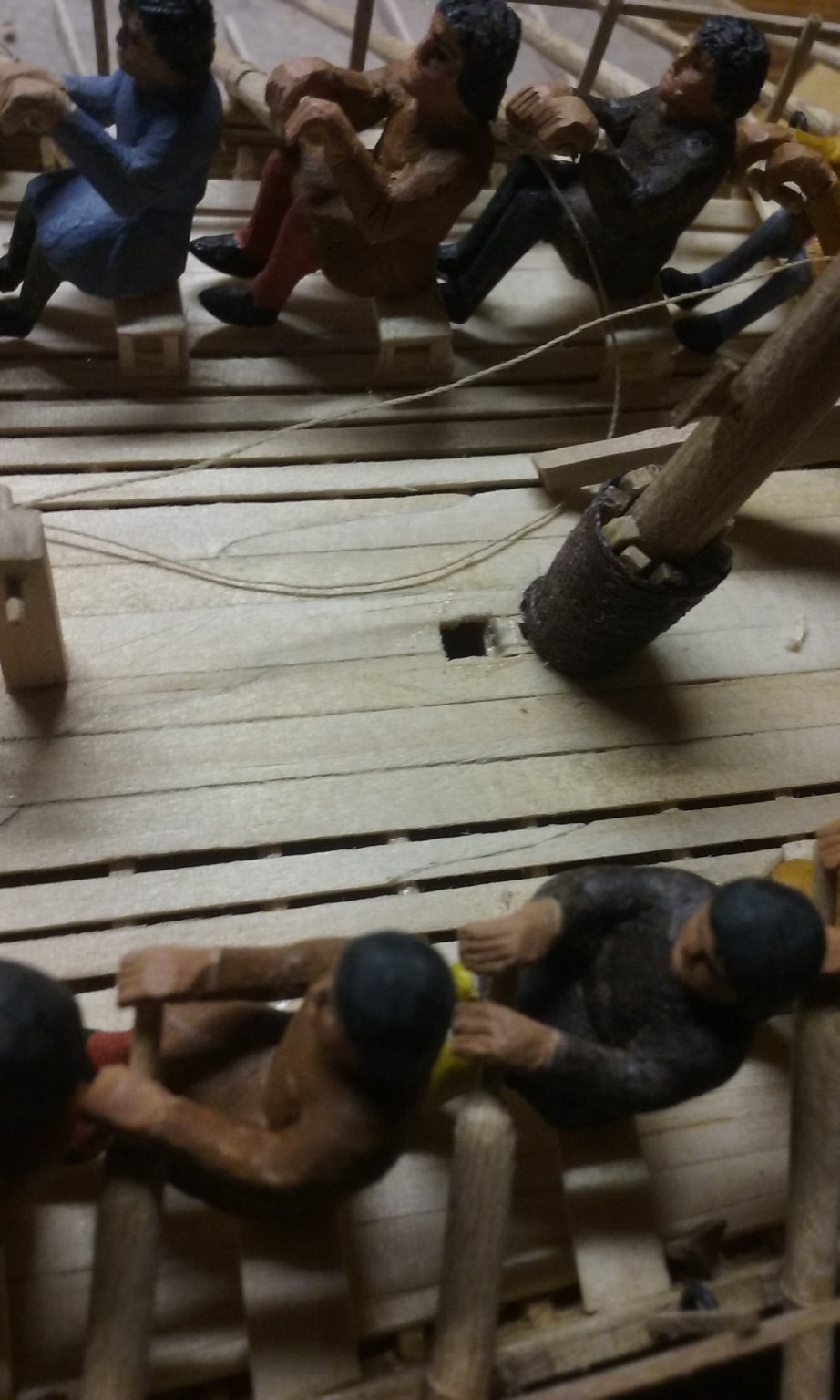
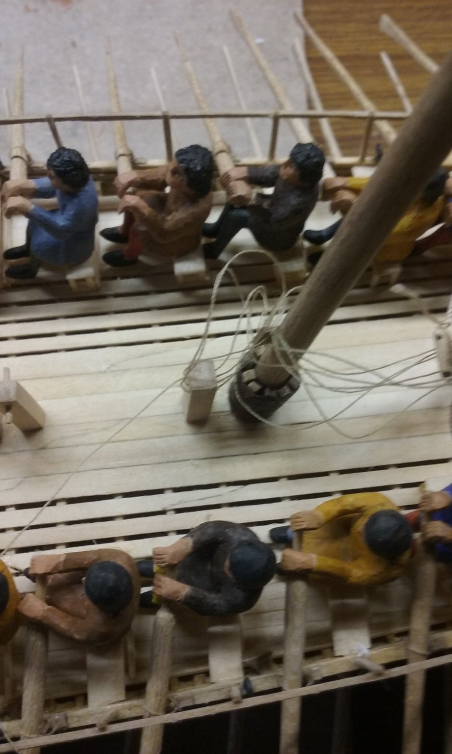
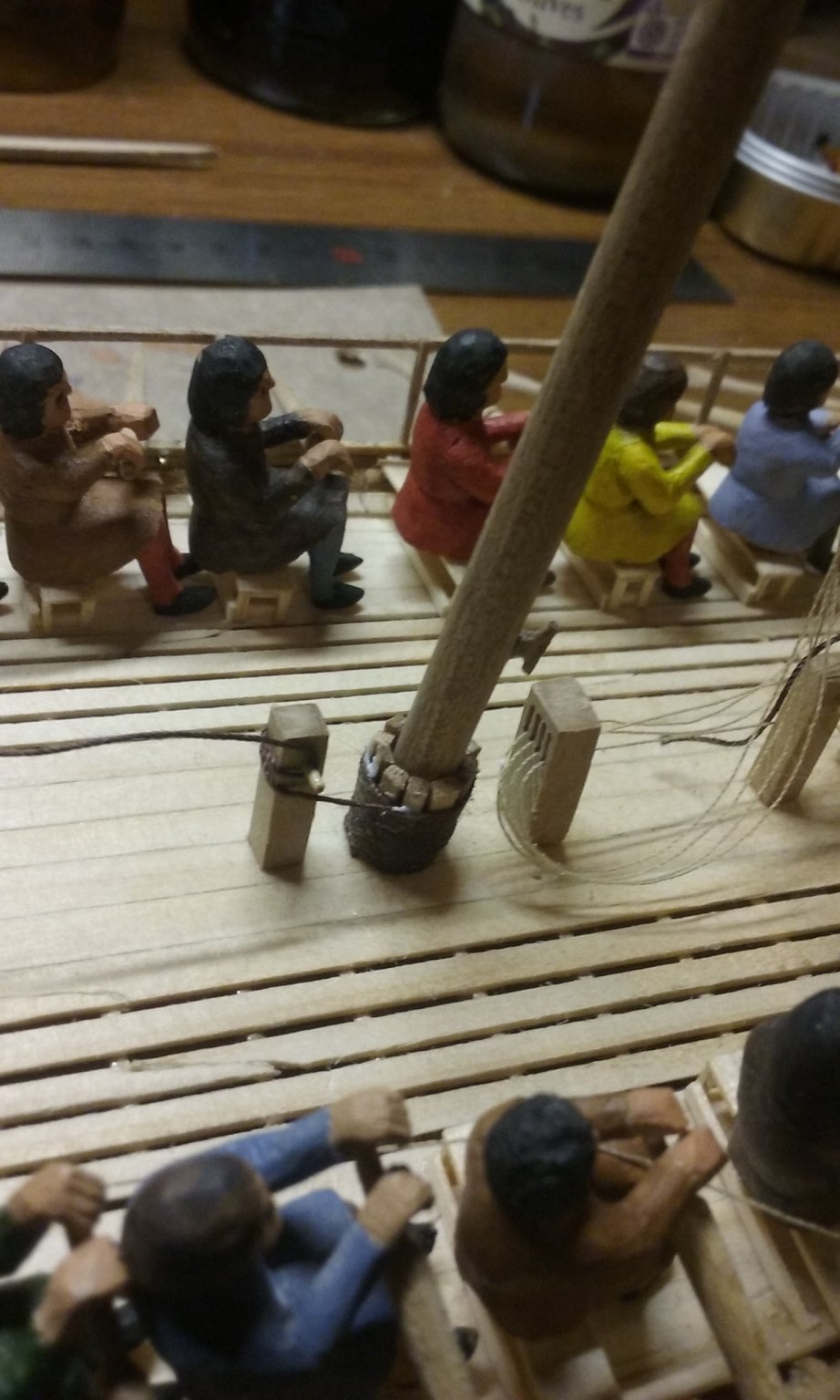
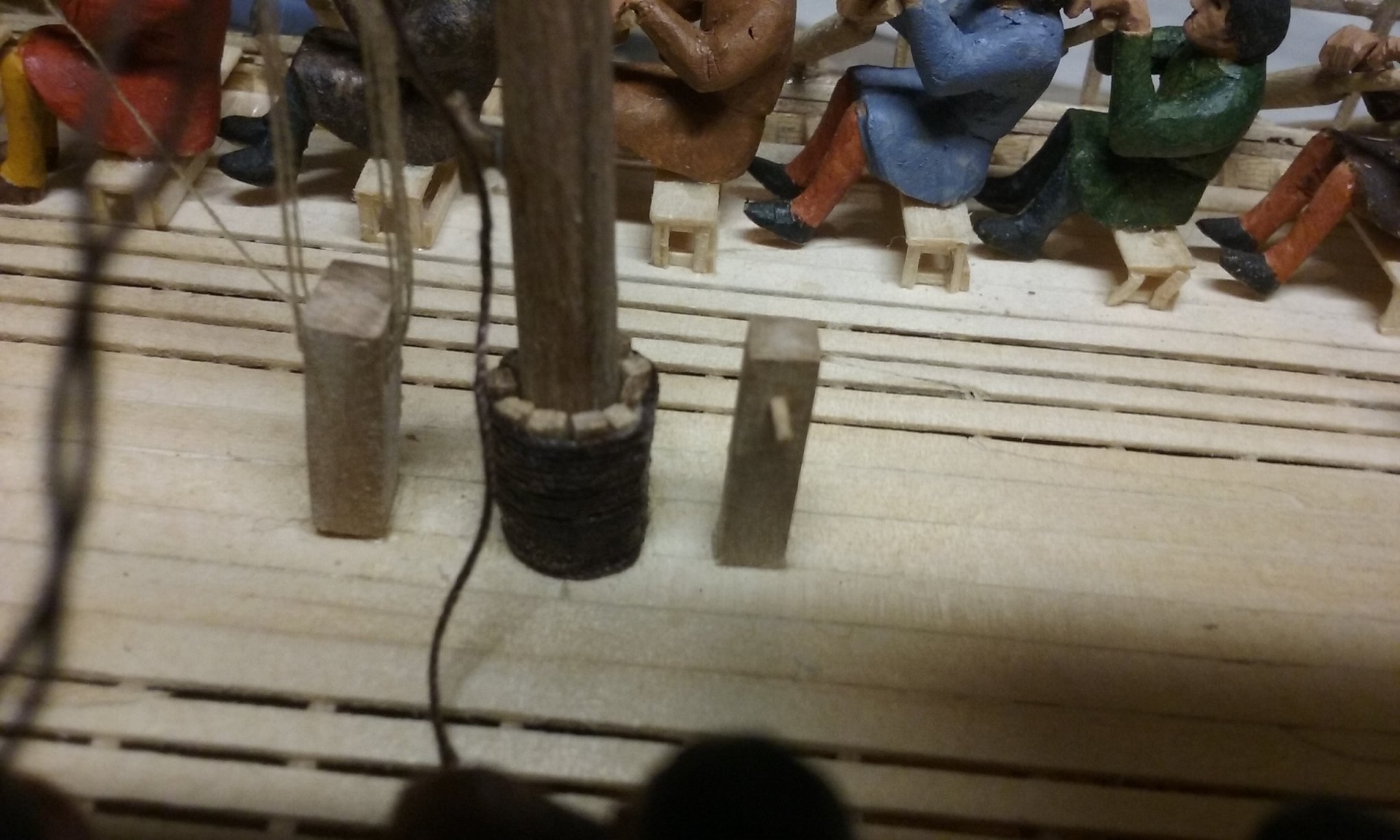
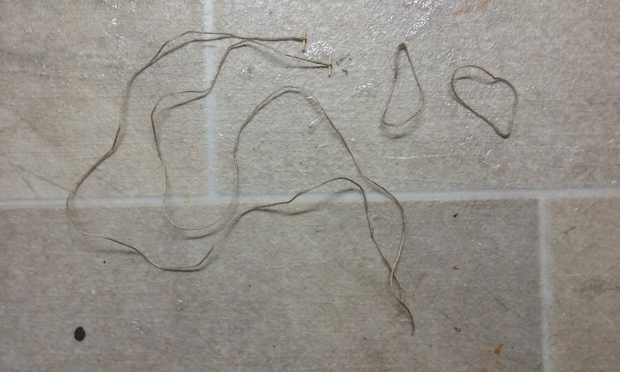
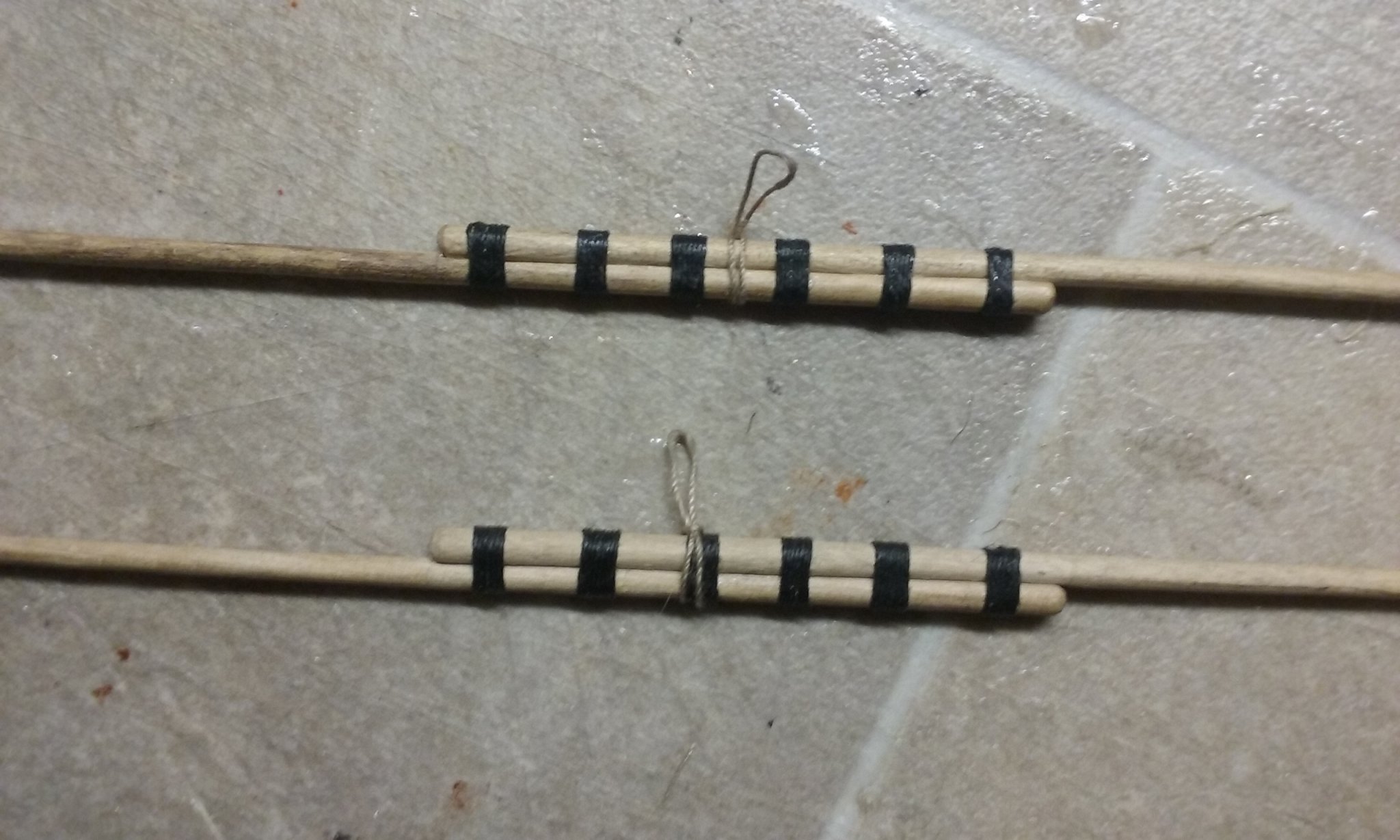
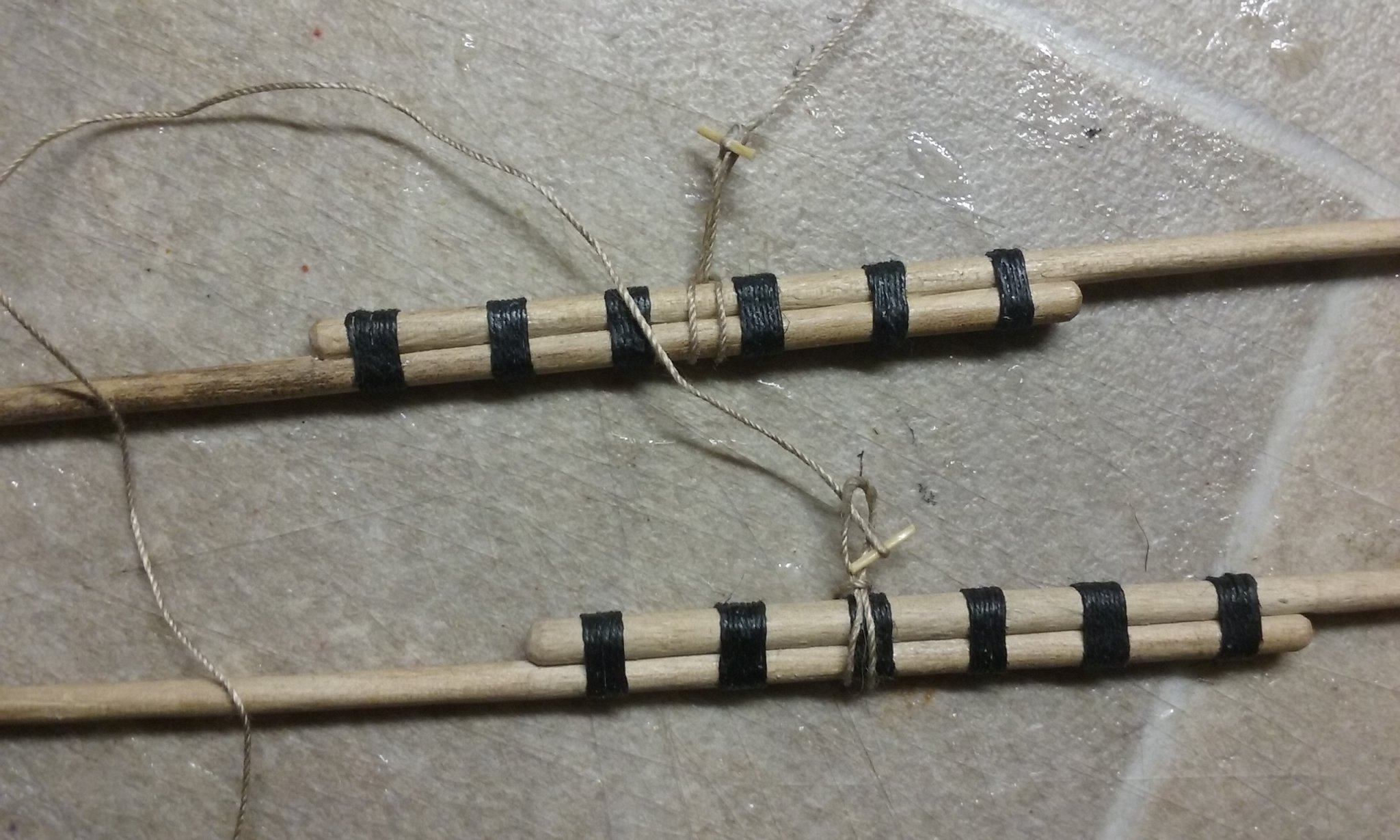
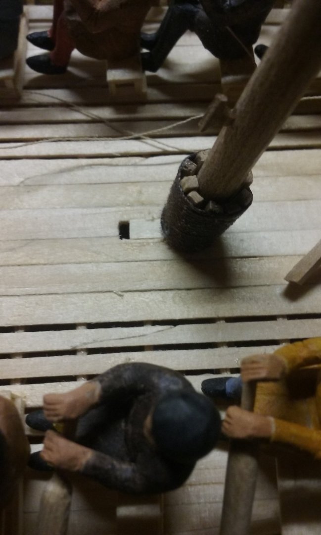
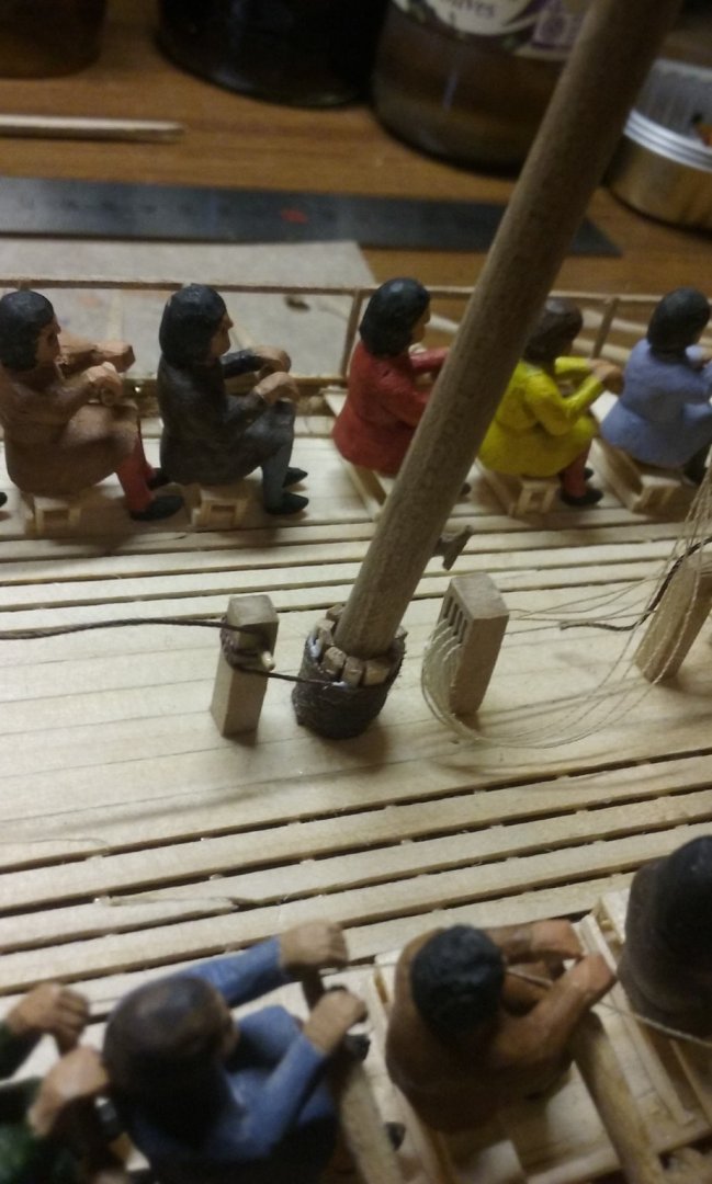
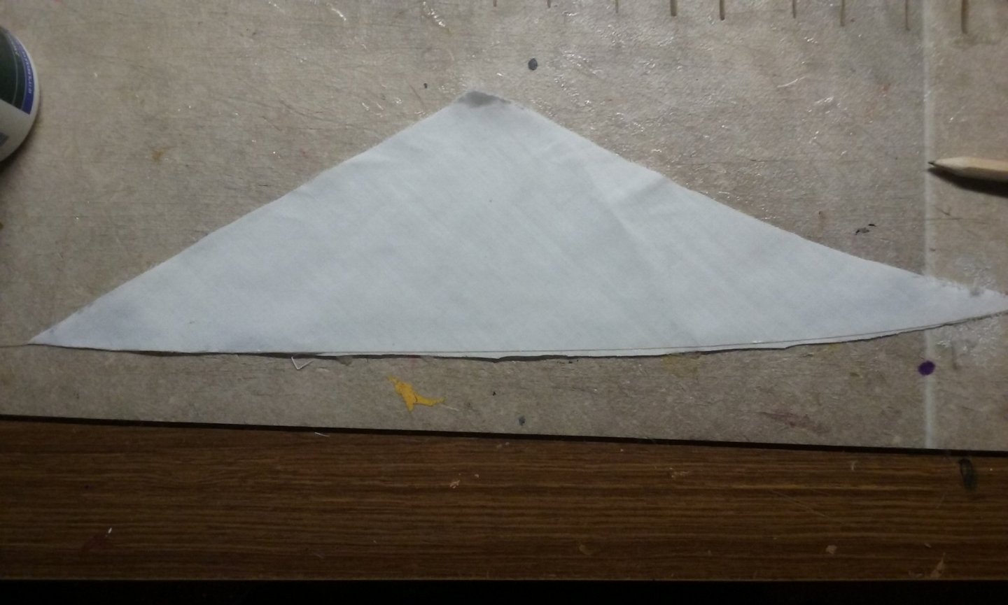
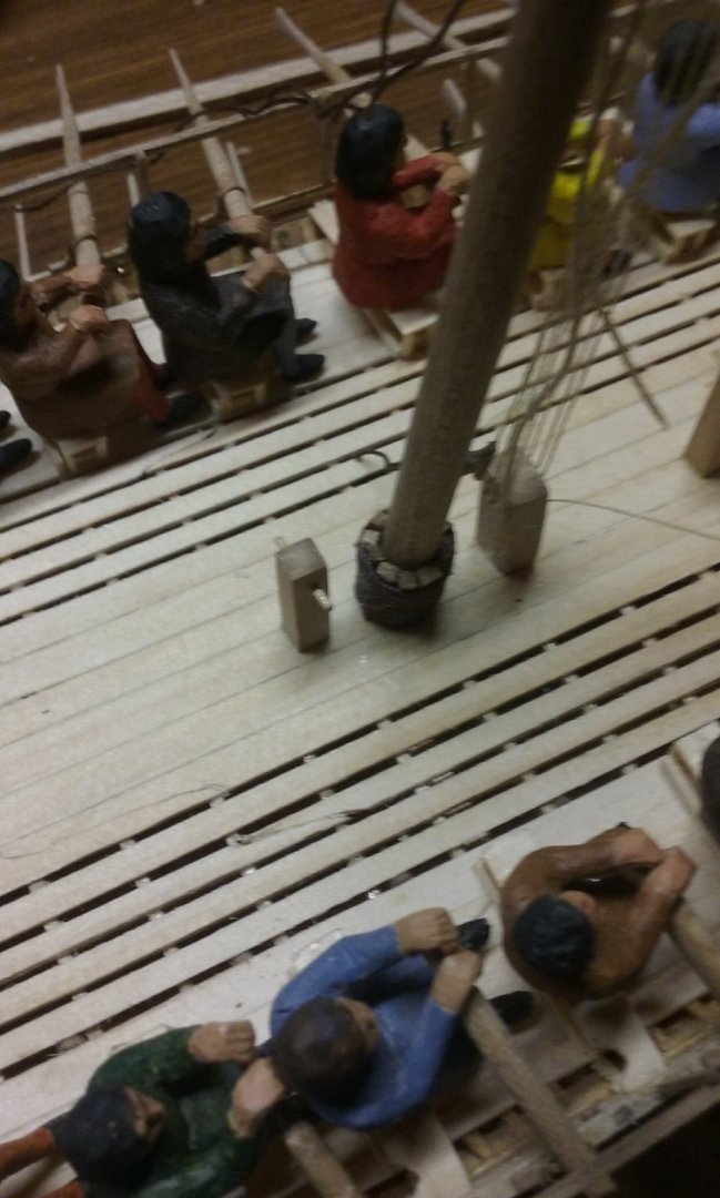
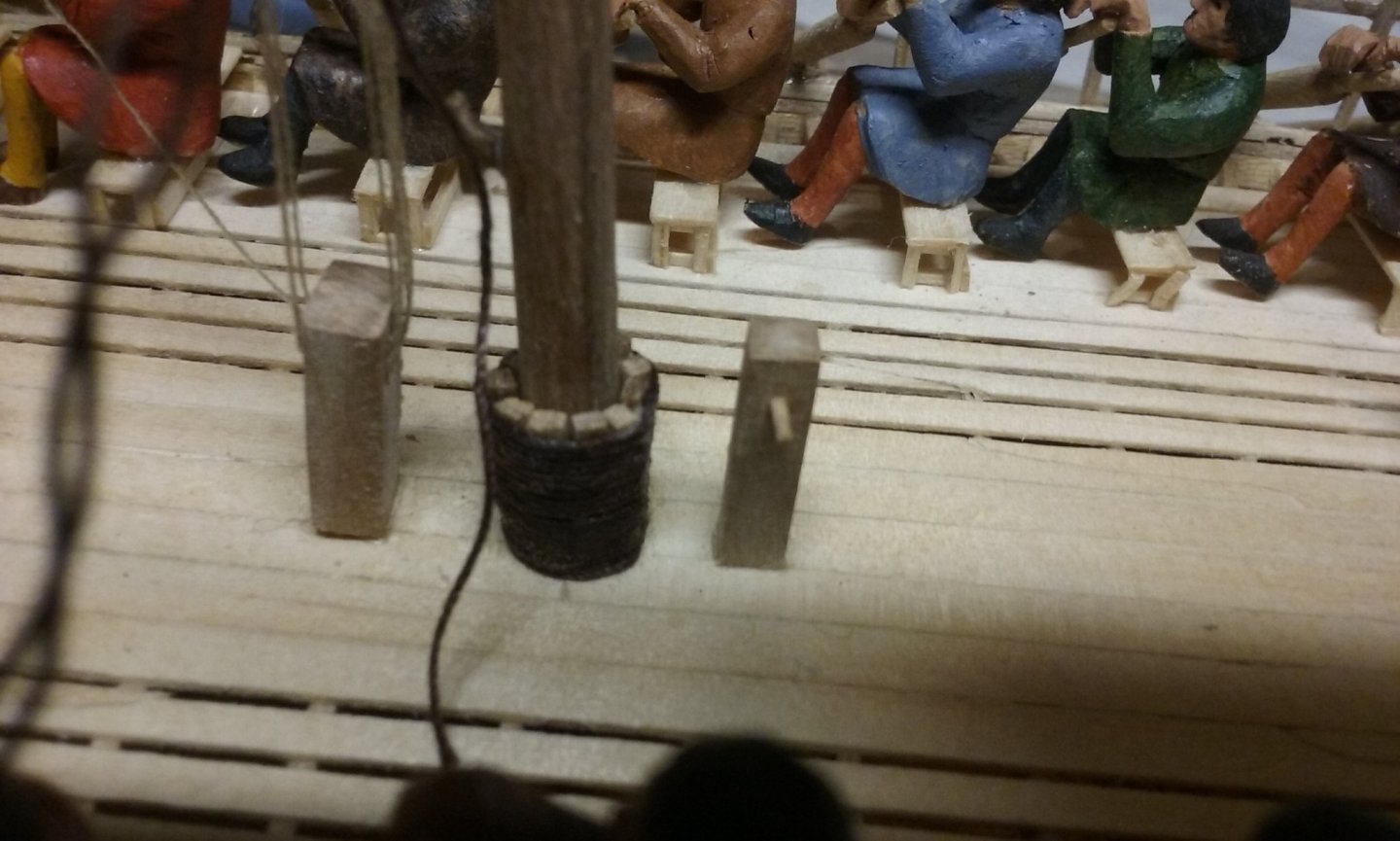
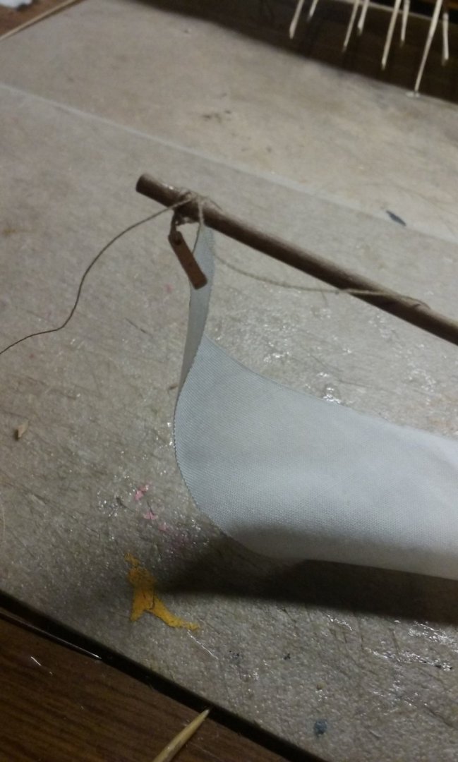
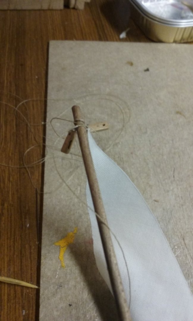
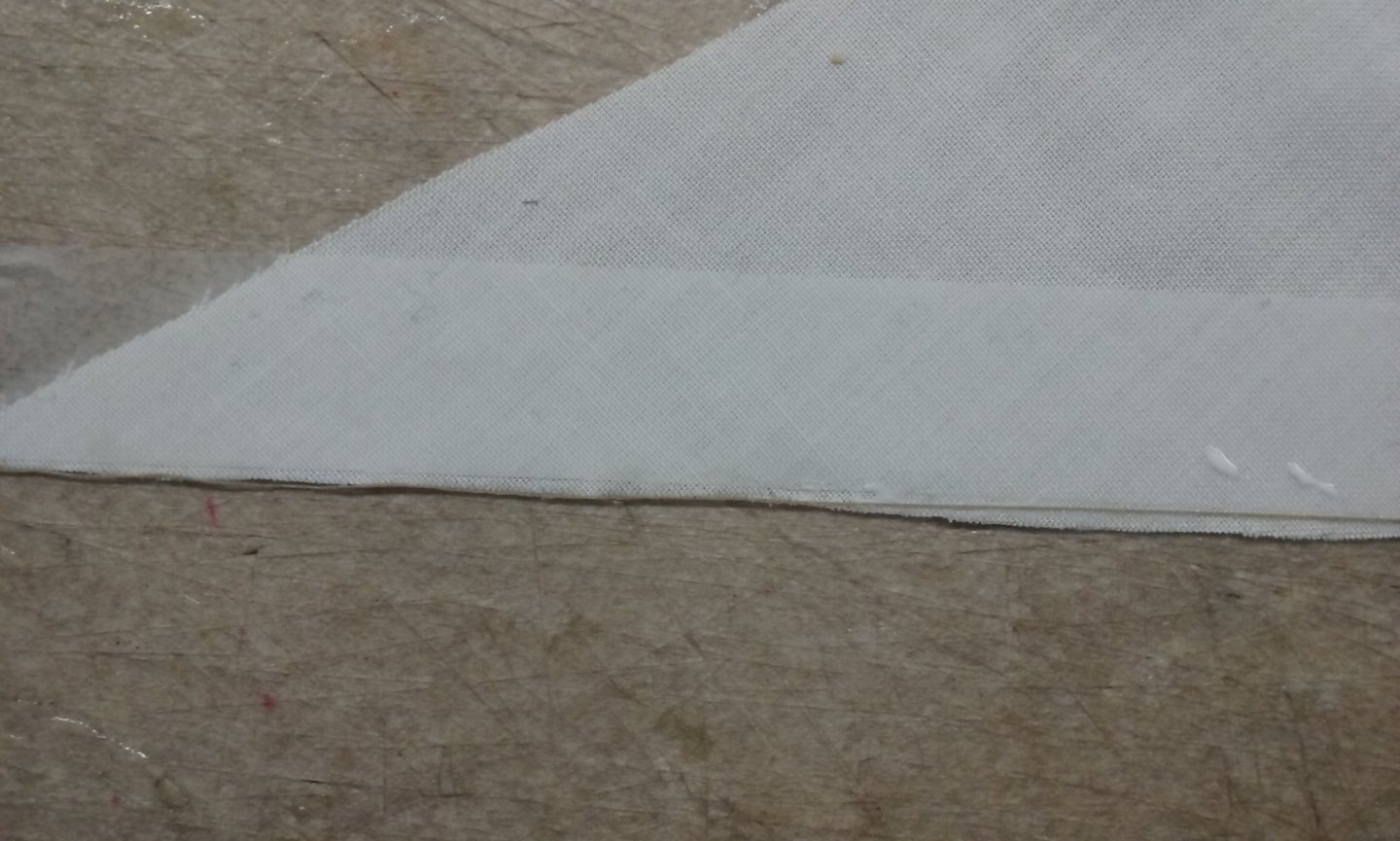
The wooldings for the after mast wedges in progress, and complete: Foremast - as mentioned above the halyard knight needed to be moved aft so the mast didn't foul its operation. Here is the deck with the knight removed, then with the slot in the deck extended aft and a new length of plank inserted to close up the gap, all the way to the mast. Then I trimmed the gap so the tenon of the knight fitted exactly into it and relocated the knight to allow enough room for its lanyards to run freely. I started making the lateen sails. As they are going to be furled I made them narrower than full size so they wouldn't be too bulky when furled. Unfortunately the first method I used didn't work - I cut the fabric out, then taped it down and glued the bolt rope to the top of the sail (the bit that goes against the yard). But as the fabric was cut on the bias - i.e. at 45 degrees to the weave - the sails mutated. You can see below that the straight line I'd cut along the horizontal had stretched downward, pulling the ends inward - I trimmed the cloth against the bolt rope, but when I measured the sails against the yards they were quite a bit too short. So I started again. This time I didn't cut the fabric until the bolt ropes were glued in place, which kept it from deforming. And when the glue was dry I cut the sails out. Now, because I'd allowed extra fabric in case they shrank the sails were too long, so I cut them to length and everything worked very nicely. Now I'm in the process of fixing the first sail to the yard with robands - a lot more fiddly and difficult than I'd expected - and very frustrating; I have great difficulty tying a reef knot in cotton thread - fingers too clumsy, tweezers keep on slipping at the last moment - I've finally taken to tying a thumb knot and adding a dab of glue, allowing it to dry and coming back to finish the knot. Very time consuming. I took the third photo from a funny angle, so it looks like the sail starts a fair way down the yard. In fact it comes all the way up to the blocks - the end part is just flipped on its edge so you can't see it. While I'm waiting for the glue to dry I've been getting the halyards themselves sorted out and attached to the yards: That's all for now. More to follow as I get more done.


-
How are sails fixed to yards?
Louie da fly replied to Louie da fly's topic in Masting, rigging and sails
Another question. The robands were tied up with reef (square) knots - what was done with the free ends? The diagrams above show the roband barely long enough to make the reef knot, but that seems impractical to me. Were they really that short, or were the free ends longer, and if so were they just left to flap around as in the picture below? Note that my question specifically relates to lateeners, but I'd assume the technique would be the same whatever the rig.
-
A very nice result. Hard to believe it's your first model. Plank length varied, presumably according to the length of timber availablel, but for example the Sutton Hoo ship'splanks were 18 feet long (see . By the way, I think the shifts in your planks are likely to become less obvious when you put the deck furniture on.
- 93 replies
-
- 1
-
-
- santa maria
- amati
- (and 1 more)
-
Hi Phil. Could you give a side view? That would help visualise better the way the castles fit with the hull. I think there should probably be a bit more inward taper on the castles, and maybe the forecastle (that's still its name, even today!) should be narrower to give it more balance, both visually and mechanically. Not sure about the sterncastle - there's a contemporary Danish picture of a ship with a similarly long castle at the stern, but it's lower than yours and fits into the hull better. It also goes all the way to the mast. By the way, you probably don't need the stempost and sternpost to stick right up above the castles - they seem to get cut off at the castle in most pics I've seen. And overhanging castles would normally be supported by brackets from the hull. I'm not sure of the right name for that mast fish thing - they seem to have only been used on Viking ships. The thing that usually carries out that function is called a mast step, and most of them aren't as pretty as the Viking ones - just rectangular. I make it Sigillum (seal of) Communo . . ronus de Dovoric[um](?). The flag is that of the Cinque Ports - https://en.wikipedia.org/wiki/Cinque_Ports - of which Dover was one.
.jpg.0921c2bfe187cc7c0a6a6a21ae90a7d4.jpg)