Louie da fly
-
Posts
7,975 -
Joined
-
Last visited
Content Type
Profiles
Forums
Gallery
Events
Everything posted by Louie da fly
-

HMCSS Victoria 1855 by BANYAN - 1:72
Louie da fly replied to BANYAN's topic in - Build logs for subjects built 1851 - 1900
Knowing the amount of effort you put into ship research, is such a thing humanly possible?☺️ Steven- 993 replies
-
- 5
-

-
- gun dispatch vessel
- victoria
- (and 2 more)
-
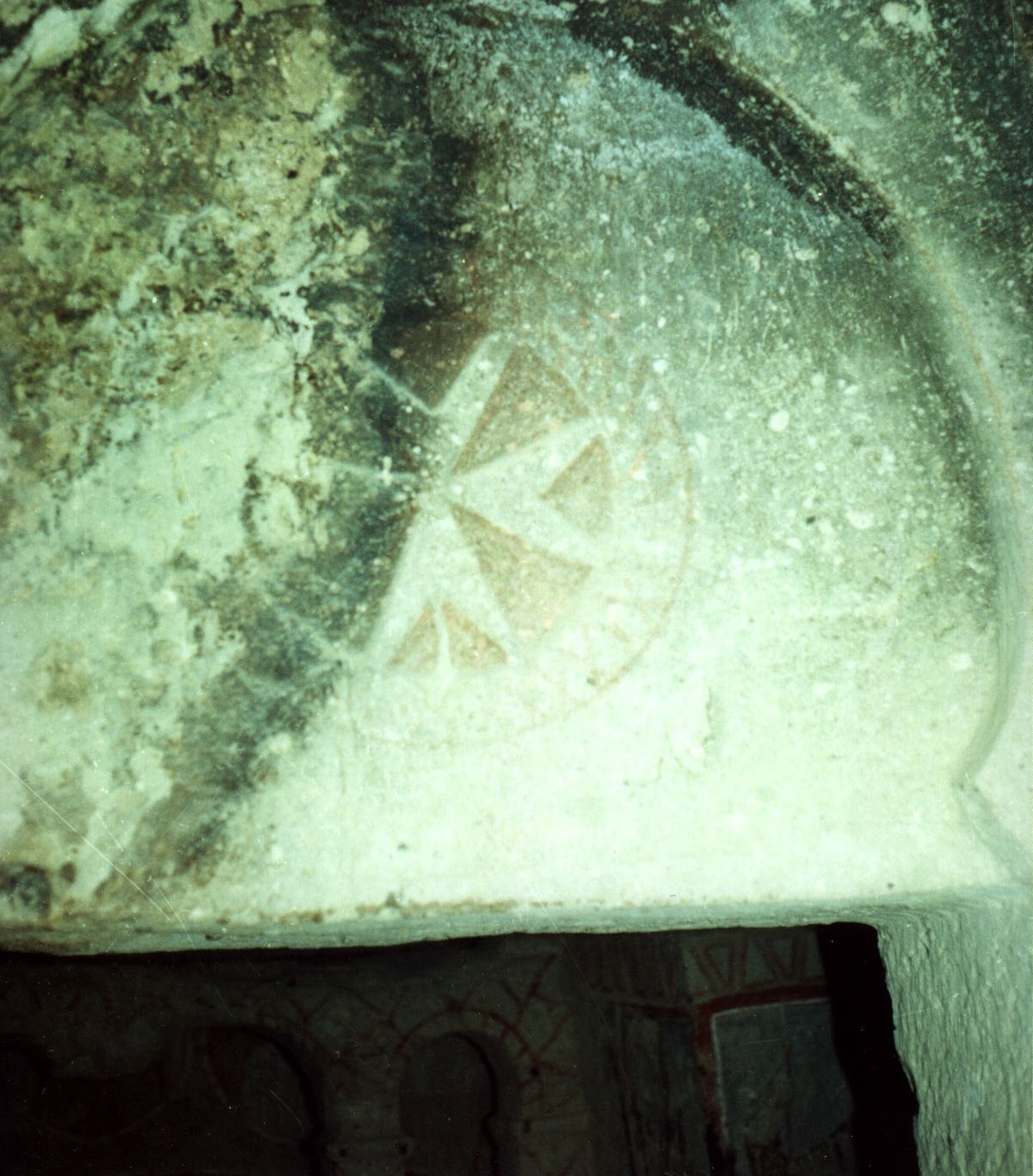
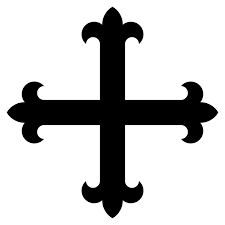
I'd never heard of the knights of Aviz. So I looked them up. Though their cross is similar to a cross moline, it's actually a cross flory/fleury - it has fleurs de lys (with an additional central "spike") at the ends. By the way the so-called "Maltese" Cross associated with the crusading Knights of St John, was used by the Byzantines and dates back to at least 200 years before the crusades. I took this photo in a 9th century (Byzantine) monastery in the Goreme valley in Kappadokia. Steven

-
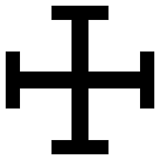
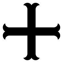
I haven't heard of them doing so. But murex purple was always a rare commodity, and I believe the Emperors wouldn't have used it for prosaic things like sails (and saddle-cloths for Imperial horses), when blue and red dye could make a perfectly acceptable purple. For their own clothing, well . . . that would be a different matter entirely. Yes, that's the kind of thing I had in mind. There are several crosses used by the Romaioi, for example the red flag at the top of this picture has either a cross potent or moline - it's a bit hard to see which it is. And I may indeed include a cross in the banner. Rather like the one here ; Oh dear, oh dear, oh dear . . . Steven
-
I don't have any experience with these video games - which is probably a good thing. And certainly, the idea of "heraldry" in the western sense seems to have been alien to the Romaioi before 1204, and even after that it was only sporadically followed. But now that you mention purple this is a Byzantine fabric from about 1000 AD. It's from the shroud of St Germain and is in purple silk with gold (single-headed) eagles. If I were to put an eagle banner on the ship this is what I'd use as a model to base it on. If I recall correctly, this is one of those purple fabrics I mentioned dyed with madder and woad, not murex (much cheaper). As the dromon has two masts, perhaps there's room for two banners. However I'm in two minds about it because there are no contemporary pictures of ships flying banners anything like as complex and sophisticated as this. Steven
-
What he said. Couldn't agree more. Steven
-
Oh, I don't know. If it's good enough for the Byzantines . . . . Steven
-
HMCSS Victoria 1855 by BANYAN - 1:72
Louie da fly replied to BANYAN's topic in - Build logs for subjects built 1851 - 1900
Nice work, Pat. And beautifully consistent. I see you're using an inch ruler for comparison, presumably for the benefit of our American cousins?😁 Steven- 993 replies
-
- 7
-
-
- gun dispatch vessel
- victoria
- (and 2 more)
-
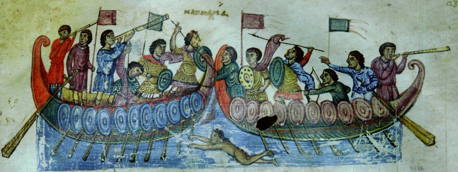
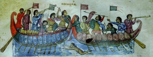
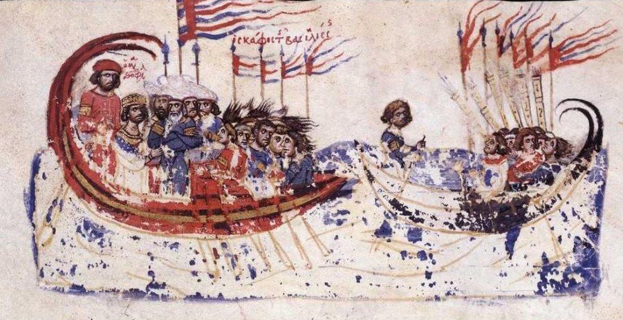
Thanks, Nikiphoros. I believe the big complex banner probably is the sign that "the Basileus is here". There has been considerable study on Byzantine banners, including a very comprehensive paper by Andrea Babuin which I should have somewhere unless I've lost it. The Synopsis Historion (also popularly known as the Skylitzes Chronicle) which can be accessed in full at http://bdh-rd.bne.es/viewer.vm?pid=d-1754254 contains quite a number of banners. Then there's the sea battle (Navmakhia) from the 11th century Cynegetica of Pseudo-Oppian, though I must say those aren't very interesting banners - I think I can do better than that. Don't apologise for introducing the idea of banners. It's one of the things I've definitely been intending to put on the ship. According the Prof Pryor's book Age of the Dromon, the contemporary records describe something at the top of the mast (the word isn't otherwise known) which he thinks must be a flagpole. I think there's only one "flagpole" on the ship in my previous post, and that the other banners are attached to the ends of spears. Steven
-
Thanks for all the likes. Nikiphoros, the 12th century illustrated copy of the Synopsis Historion by Ioannis Skylitzes held in the Madrid Biblioteca Nacional has quite a few pics of galleys with banners. I'll be following this one, as it's a ship carrying the Emperor. The Lascaris double-headed eagle and the banner with the repeated letter B (as on your post, but in red and yellow) didn't come into use until a couple of centuries later. As far as I know, the sail would have simply been the natural colour - certainly there's no evidence to suggest anything else. And murex would have been prohibitively expensive - though several surviving pieces of Byzantine fabric in "Imperial purple" turn out to have been dyed with madder red and woad blue to make purple. Steven
-
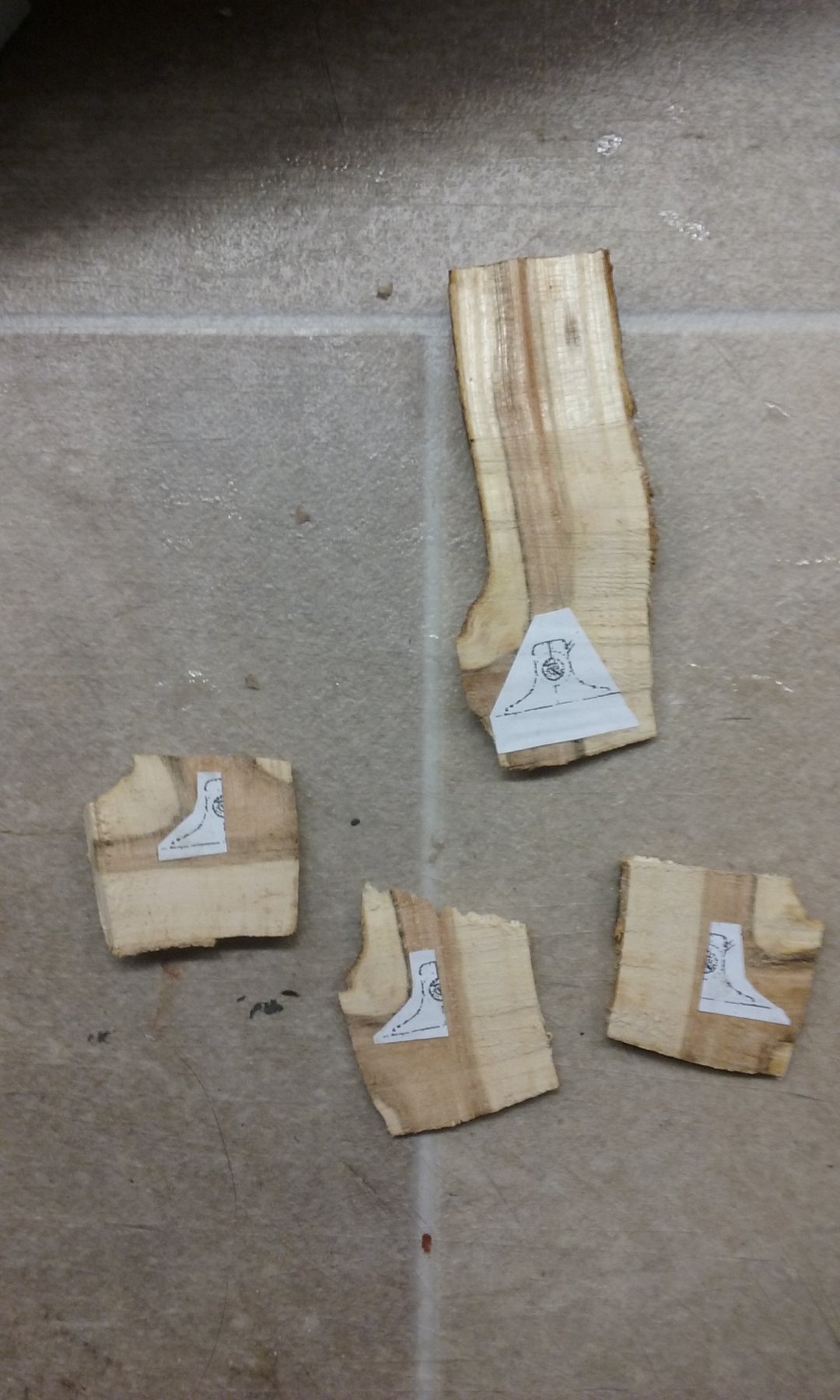
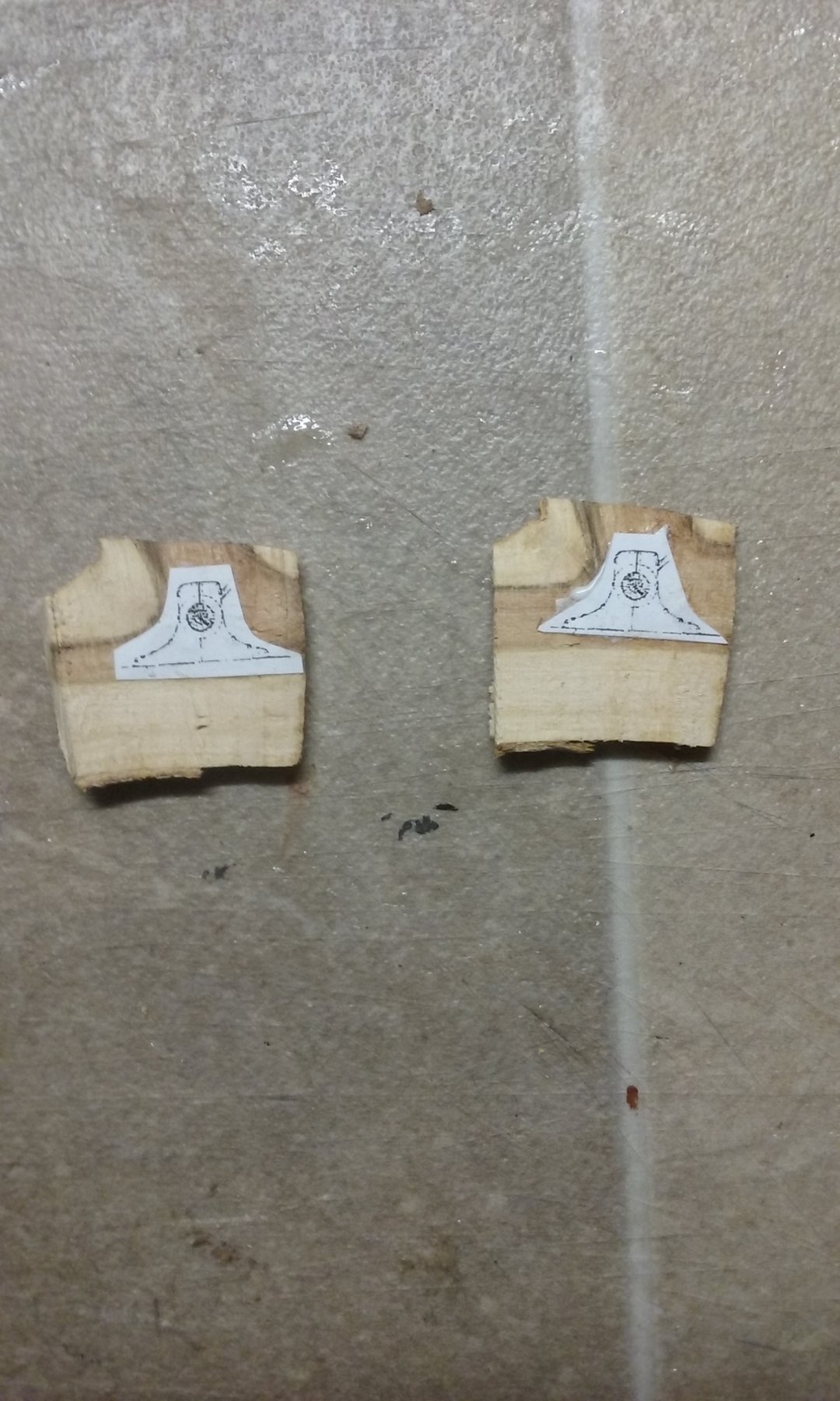
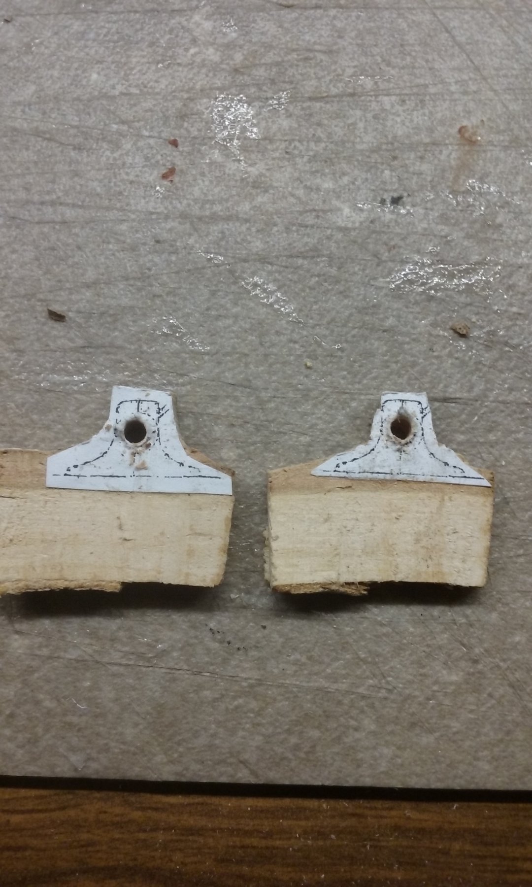
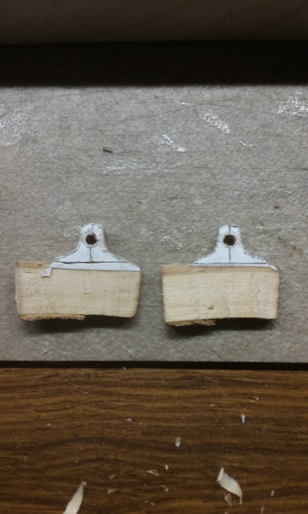
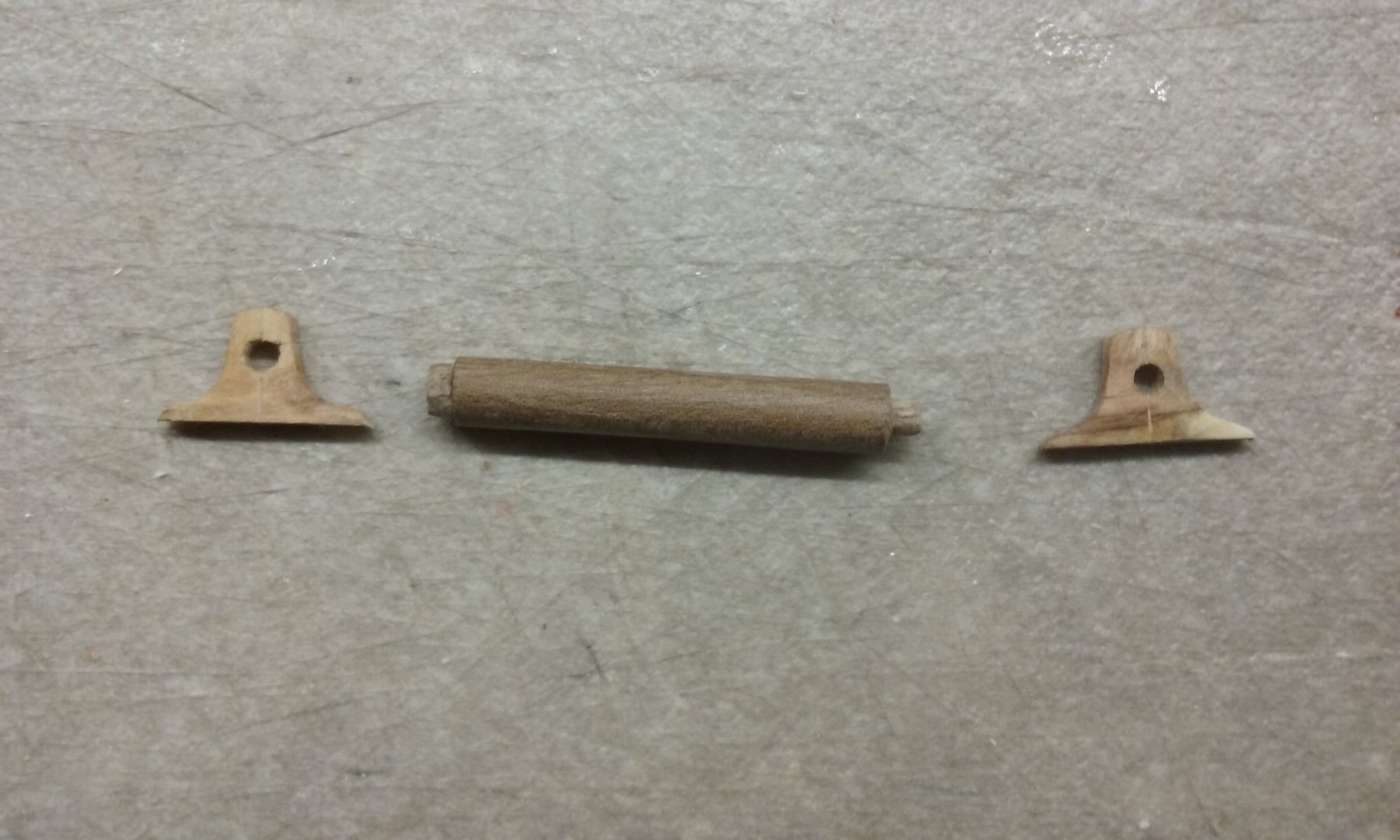
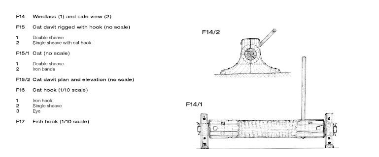
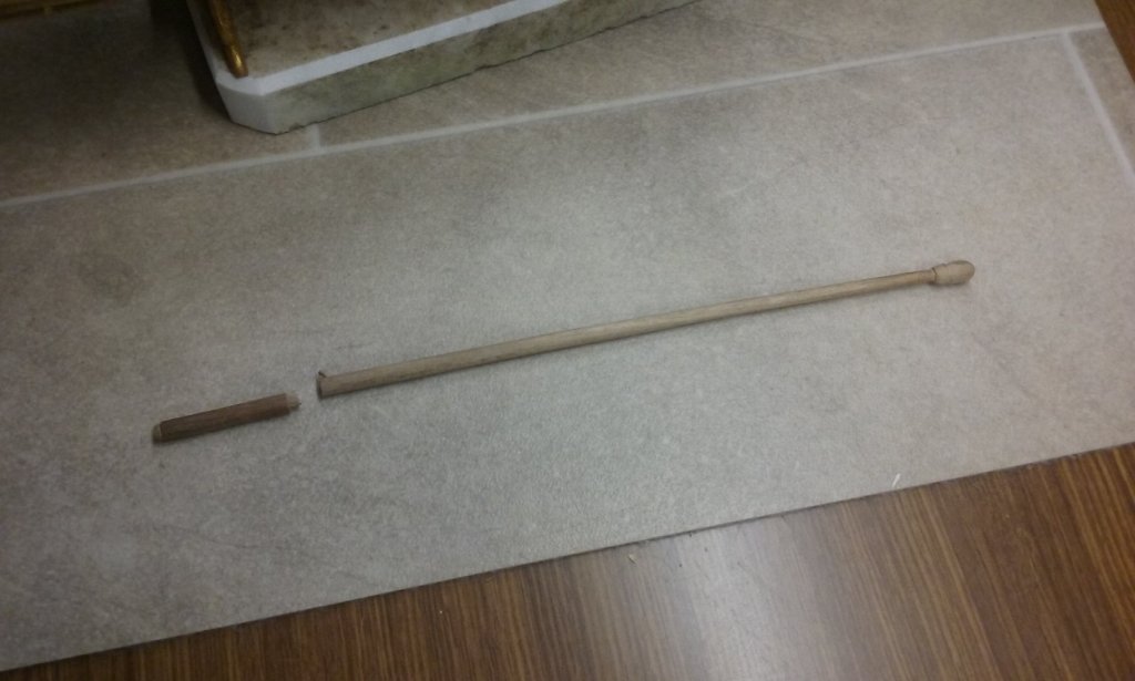
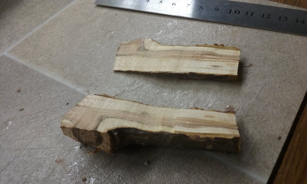
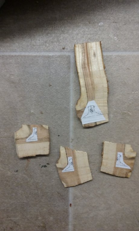
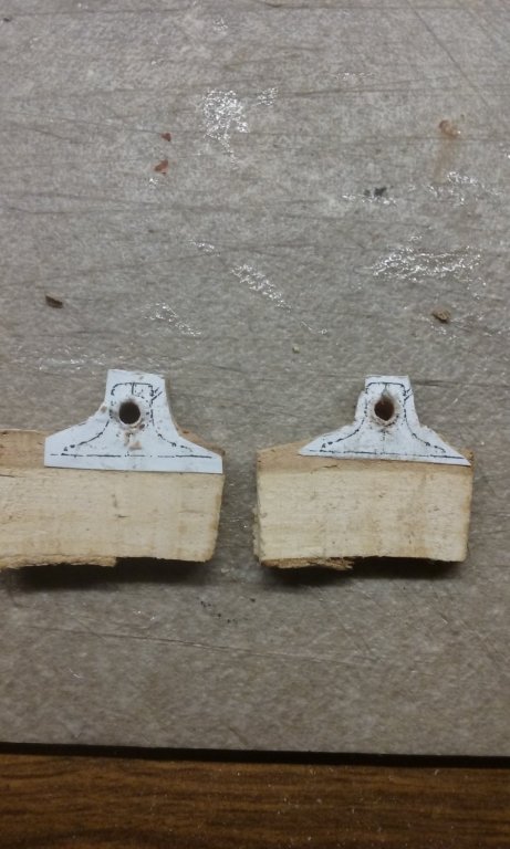
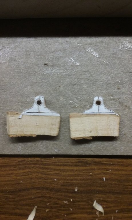
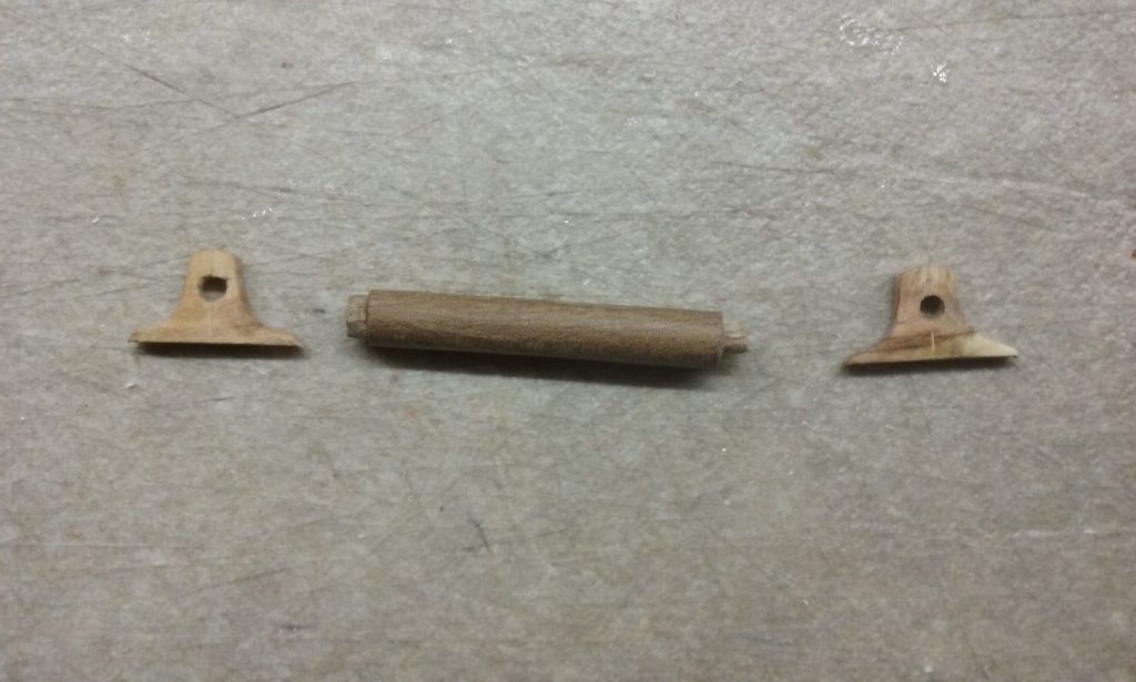
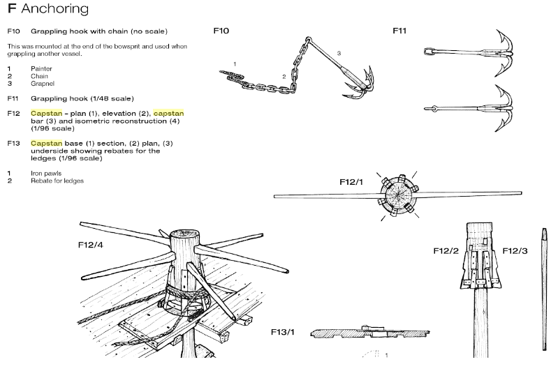
Working on the windlass, using the Mary Rose's windlass as a model - it's the earliest intact windlass I know of. If anyone knows of one closer to the 11th century, please let me know. I still have a problem with this windlass - there is no pawl, so I don't know how to keep the windlass from unwinding if the bars are released - perhaps the cable was just made fast to bitts or cleats or something when it was pulled up far enough. I recycled a mast which had bowed and had to be discarded, and cut a bit off it to make the barrel of the windlass. I started out using a bit of branch from a plum tree I'd been holding on to for years, as it's got a join between the branch and a lesser branch, which should give a good grain for making knees. I cut four slices from it, photocopied the Mary Rose windlass down to scale and glued four L-shaped segments for the two ends (two for each end) onto them. But it turned out I'd cut two of the pieces too thin. As I only had one piece of wood, I thought I'd wasted my efforts. Then I realised the piece of wood actually had a T-shaped grain, so I could make each of the ends in a single piece and carve a fake join between the two "halves". Unfortunately, this meant the grain pattern in the two end pieces was continuous instead of being in two halves. But I think I can live with that - if all else fails, I'll paint the ends to hide the grain. Steven


-
Looks very good, Tom, and the scale looks right. I agree about the colour for yours. I'll be using tulle for my Great Harry, but as it's at 1:200 I find that a lighter colour vanishes at that scale, so I used black. Anyhow, the nettings on 16th century ships were pretty much permanently fitted, right over the top of the decks, and weren't used to store hammocks in between times. Steven
-
You've certainly transformed this model, Daniel. Very impressive. Steven
-
A wonderful project to undertake, Chidokan. I find ships of this period fascinating. I'm currently restoring my own scratch-built model of Mary Rose's big sister, the Henry Grace a Dieu (or Great Harry) that I built when I was 17. That was before Mary Rose was raised, so a lot of the details in my own model are wrong, but I think it's worth returning it to its original glory. You'll find everybody here very helpful. Don't be afraid to ask questions, and don't worry if you make mistakes - we all do, even the best of us (in which group I don't include myself). And have fun with it! By the way, a heads-up on the Jotika model. The Mary Rose's forecastle has never been found (though I live in hope), and most reconstructions of her, including the one at the Mary Rose Trust, show her with a forecastle I believe to be incorrect, and more appropriate to a galleon than to the Mary Rose. I raised this issue on this forum at The forecastle still hasn't been found, but I'm still of the opinion that the "official" one isn't correct. Look at the Anthony Roll picture - doesn't look at all like a galleon's forecastle. Perhaps you might consider "bashing" the forecastle to be more like the Anthony Roll one. Regarding the discrepancy between the Anthony Roll and the number of guns believed to have been on board the wreck, there's an analysis of how many of each type of gun she carried at https://en.wikipedia.org/wiki/Mary_Rose, which might be of help. Good luck with her. A very well worthwhile model to make. Steven
-
Still remembered. The sacrifice of all those young men for a campaign pretty much doomed at the start, because the Turks knew they were coming and were well prepared. Steven
-
I agree. Galleons had certainly made their appearance by 1545, with the characteristic beakhead and low forecastle. It will be interesting to know whether this vessel is one of them, or is old-style. I think I'd be expecting the new type in this case Steven
-
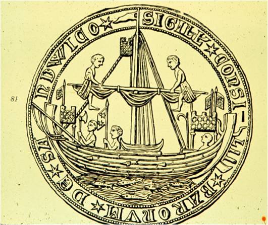
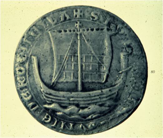
I've bookmarked this - it will be interesting to see more as the archaeological reports come in. This is really later than "Viking" times - just before "nefs" with castles in bow and stern, and I'd like to see what if any evolution can be seen from the intervening centuries. This is the seal of the coastal town of Sandwich, from 1238, which is about as early as these castles seem to have come into use. The 1188 ship is more likely to have looked like this: which is almost identical to Viking vessels. The differences are likely to be in the details, and the fact that this was a merchant ship not a warship. Steven
-
Very interesting. I look forward to hearing more about this one. Built about thirty years later than Mary Rose, but very close in time to Mary Rose's rebuild in 1536. It will be interesting to compare the two. Steven
-
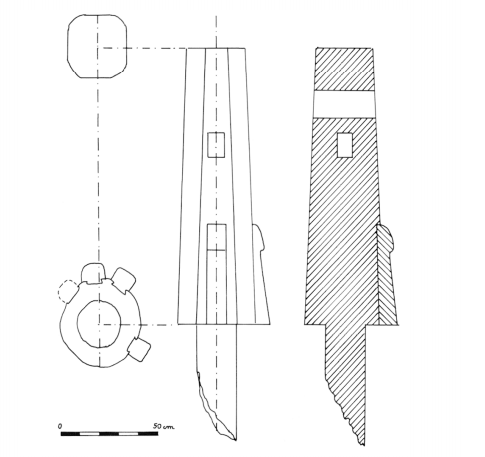
The capstan of the Genoese ship Lomellina, built in 1503, has slots for two bars,each of which passes right through the capstan. The slots are at different heights above the deck. A reconstruction of the Mary Rose's capstan (with removable bars) is shown below. This seems identical to the one Patrick is making. This illustration can be found at https://books.google.com.au/books?id=MSCGCgAAQBAJ&pg=PA108&lpg=PA108&dq=mary+rose+capstan&source=bl&ots=EjQXJE-eU7&sig=ACfU3U3vIvX3cjv7dF9GZQA9g-OfSPourA&hl=en&sa=X&ved=2ahUKEwiCyu2auM_hAhWJfysKHUzvC70Q6AEwEXoECAgQAQ#v=onepage&q=mary rose capstan&f=false It seems unlikely to me that a capstan, even as early as the 16th century, would have its bars permanently in place getting in the way. Steven
- 756 replies
-
- 7
-
-
- galleon
- golden hind
- (and 2 more)
-
A very nice exposition of how Venice came to have such a wide-ranging Empire. The only thing I'd add is that Venice, having helped destroy Europe's bulwark against the expanding influence of the Ottoman Turks, lost its own "Empire" to them in the following centuries. Poetic justice? Steven
- 263 replies
-
- 4
-
-
- nave tonda
- round ship
- (and 2 more)
-
I have a very fond memory (and a photo) of sitting in the cockpit of a Mark IX under reconstruction (if that's the right word) about 30 years ago. It wasn't in running order, let alone flying order, but it's very nice to be able to say I once sat in a Spitfire. Steven
-
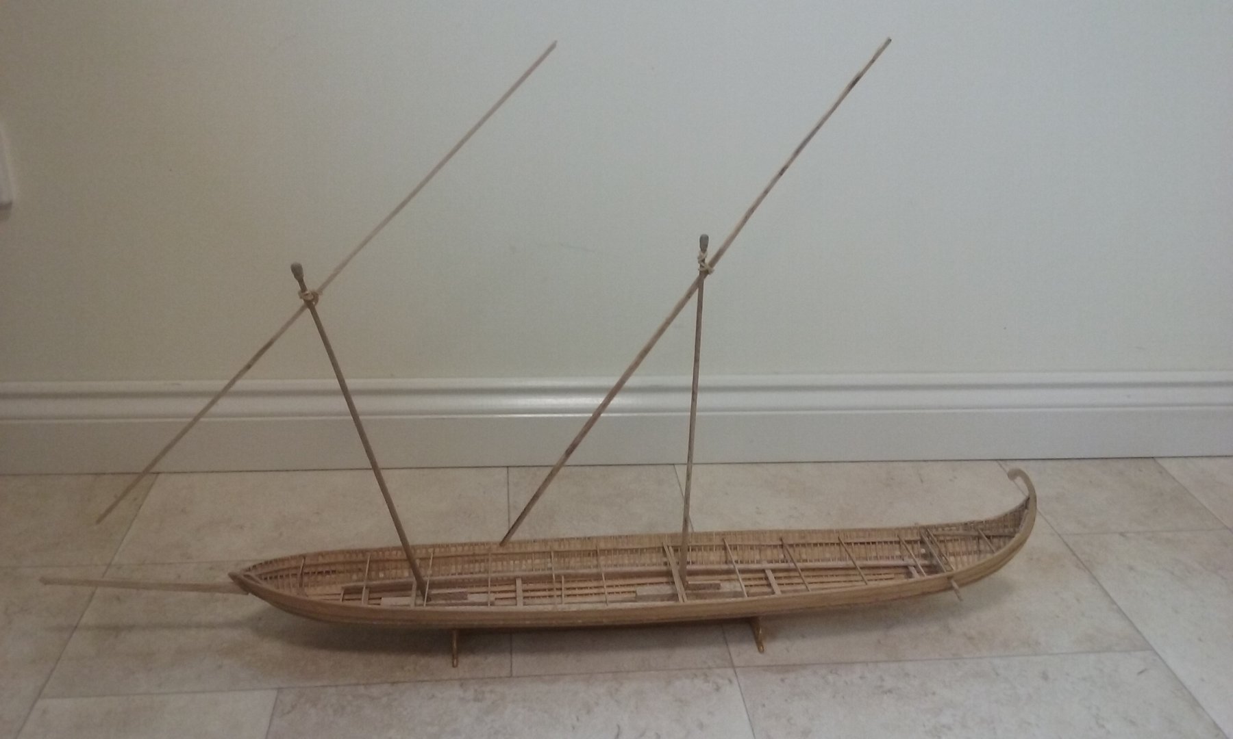
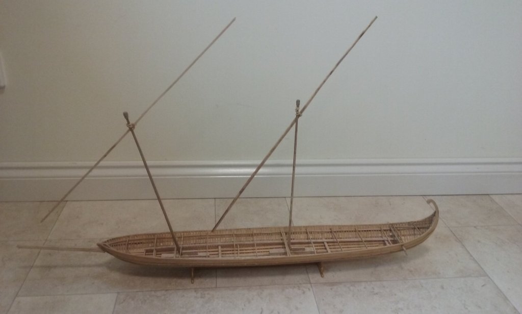
Dick, I'm inclining the same way. My masts are simple poles, as I haven't seen anything in contemporary Byzantine pictures to suggest they were built-up (not that this is any kind of proof - but it's all I've got to go on). By the way, I hadn't previously noticed that the mast in the left hand picture in your post seems to be made out of a barber's pole! Again, I agree. However, though the dhows are 19th century I think there's a fair chance they are "traditional" and have changed less than Western European examples. And I'll be using the simplest and arguably most "primitive" examples as a model to work from, on the basis that they're likely to be closer to mediaeval practice than any others.
-
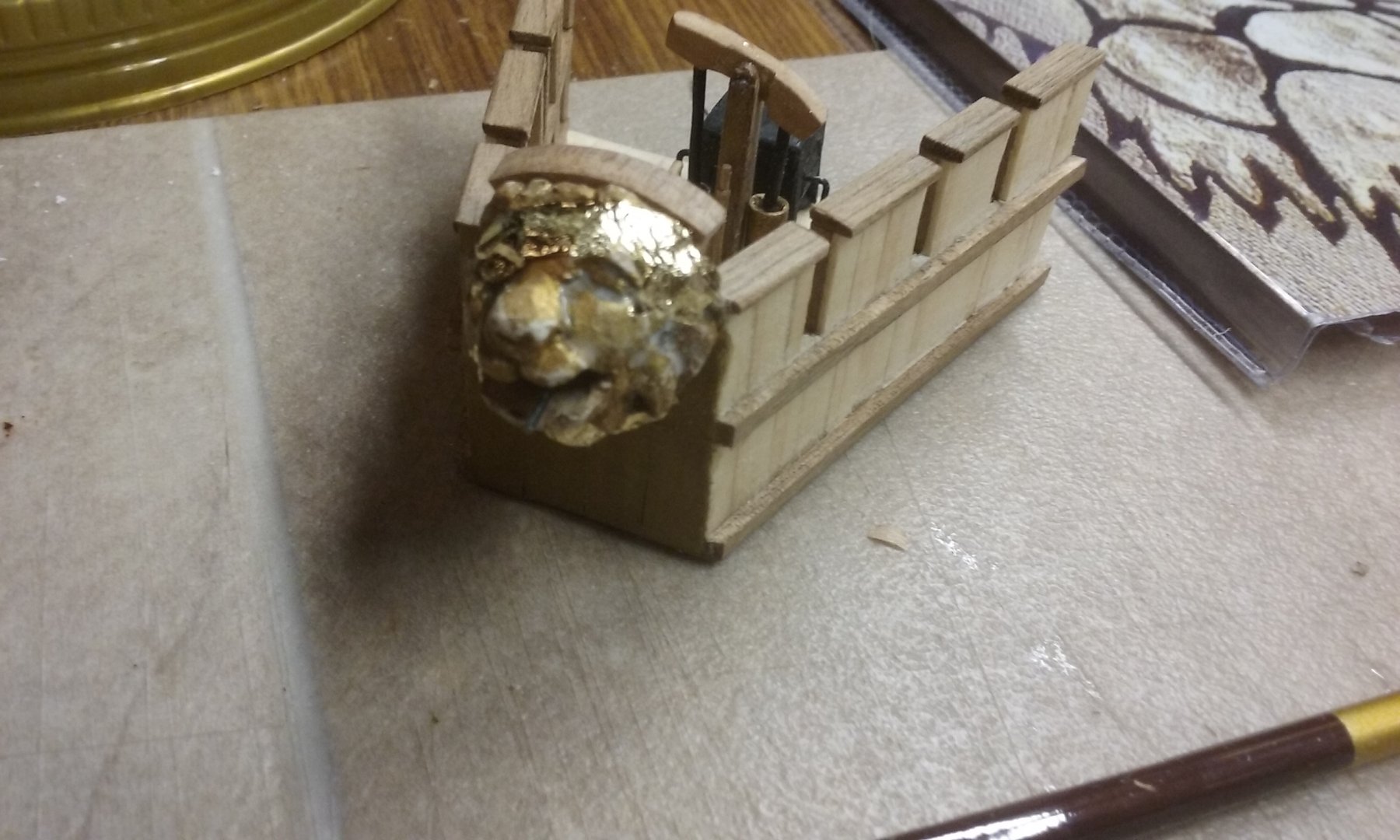
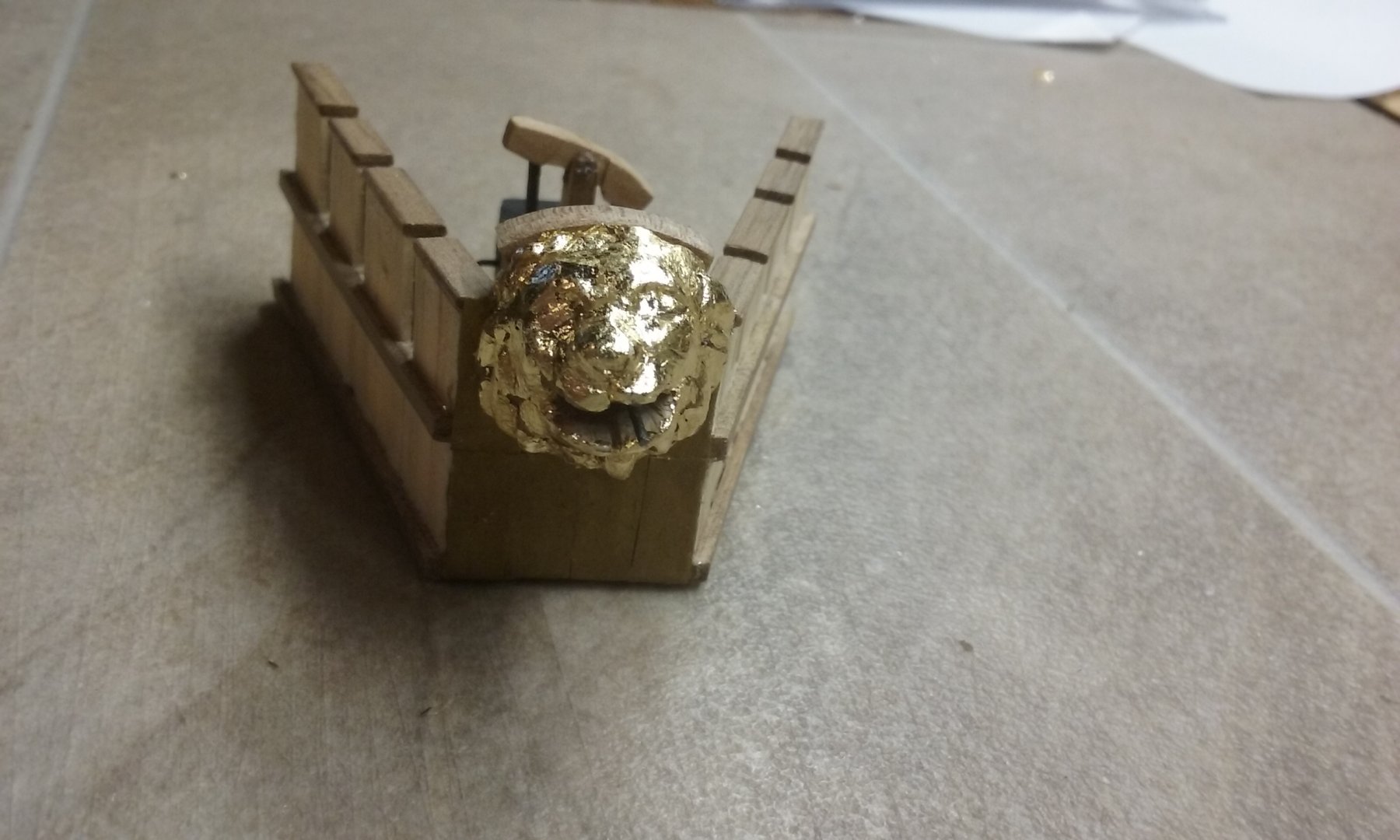
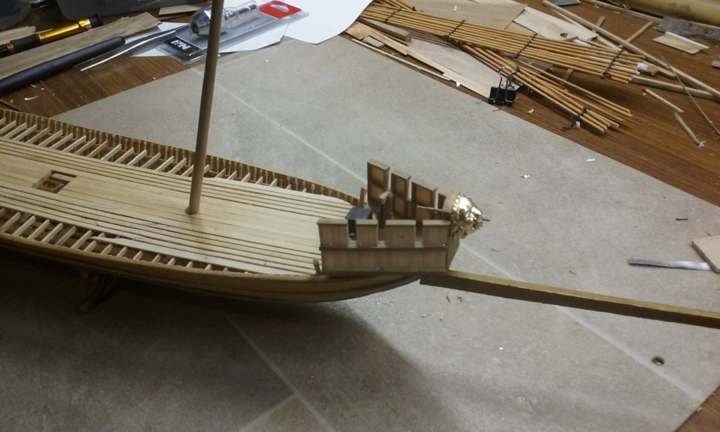
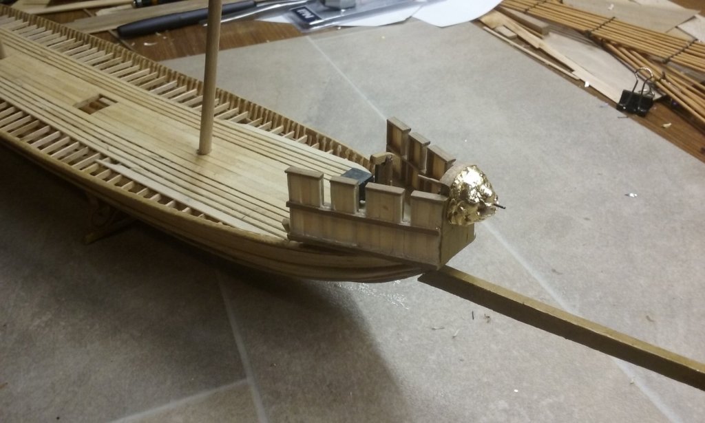
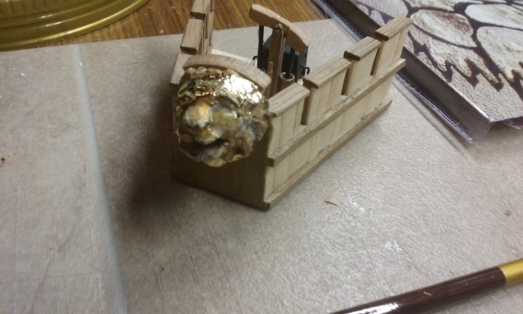
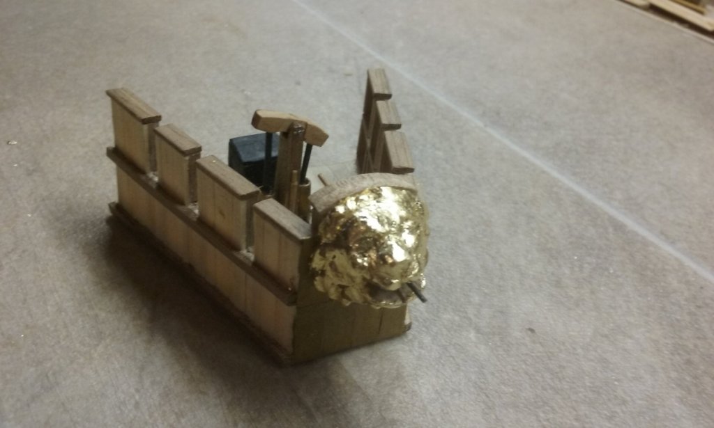
That's right, Carl. A very small brush indeed. Usually used for fine detail work. And after the glue was dry (I used dilute PVA) I buffed the exposed surfaces with the end of my finger. Here is perhaps a better idea of what the lion's head will look like when it's in place: Steven
-
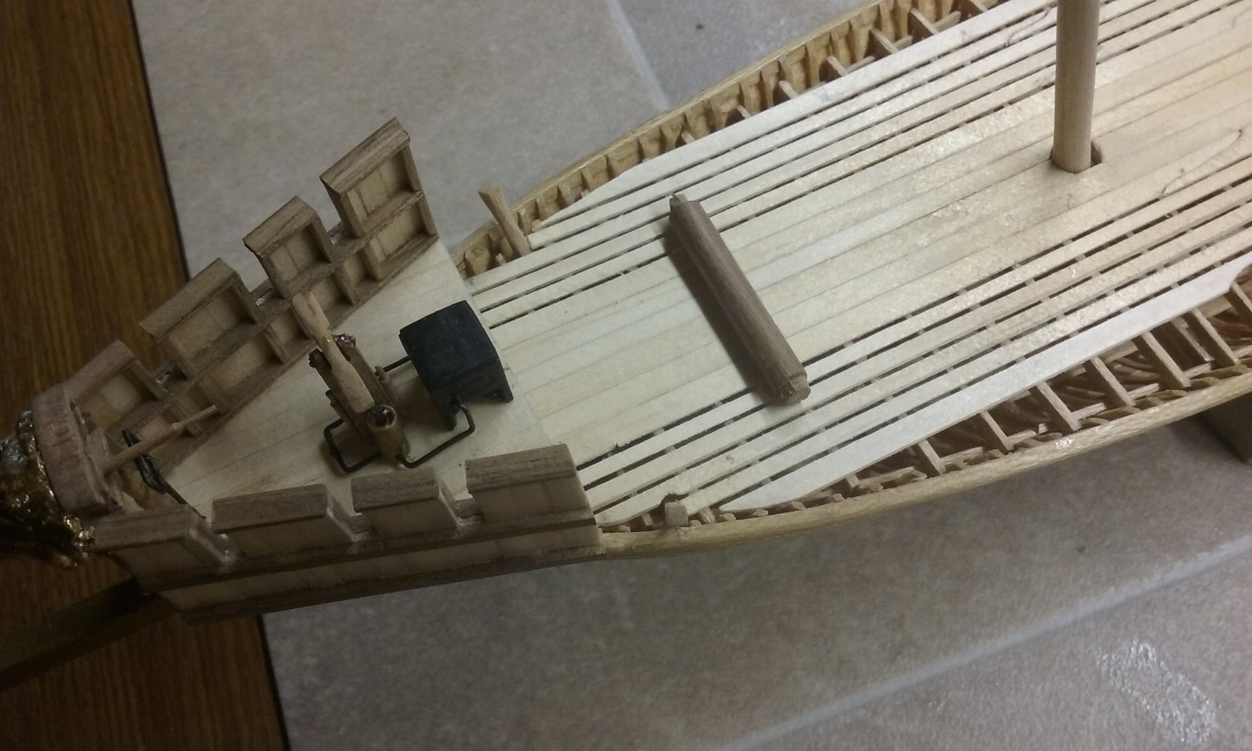
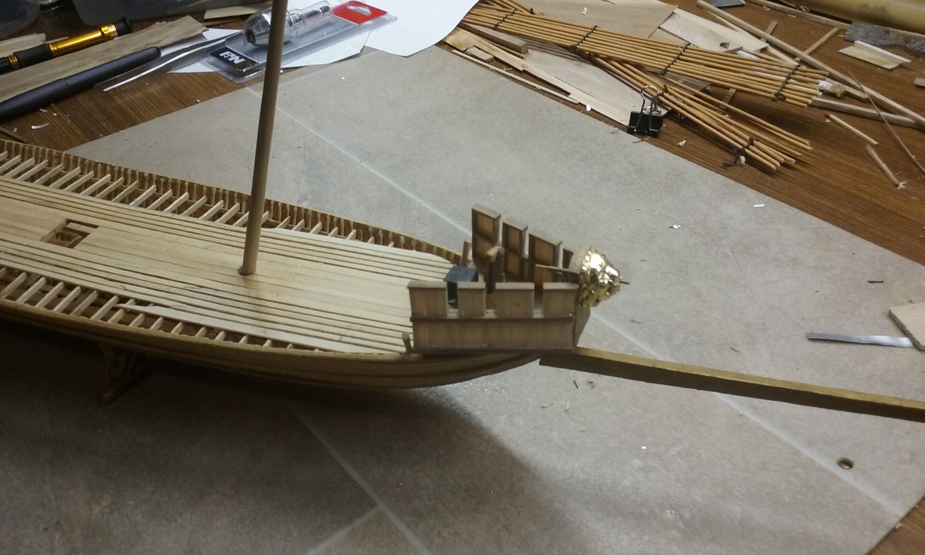
I've painted the "heat shield" at the front of the forecastle to look like bronze plating, and covered the lion's head with gold leaf, in line with the description in the Alexiad. The photos don't really give a good impression of just how shiny it is. Just starting out: And completed: A lot of very fiddly work and a certain amount of cursing. But I feel more confident now that I can put gold leaf on things fairly well. Still a lot to learn but not quite as terrified of getting it wrong as I was before. Steven

-
Thanks Alberto. I've seen that counterweight on dhow photos and wondered what it was. Another mystery cleared up. All this info should give me a good basis for the rigging for my own dromon. Steven PS: The Castle is really worth seeing if you ever get a chance to get hold of it. See https://www.google.com/search?q=the+castle+movie&rlz=1C1NHXL_enAU770AU770&oq=the+castle+&aqs=chrome.5.69i57j69i65j69i61j0l3.5590j0j7&sourceid=chrome&ie=UTF-8 for some highlights.
-
Nice precise work. Looking good. Steven