HOLIDAY DONATION DRIVE - SUPPORT MSW - DO YOUR PART TO KEEP THIS GREAT FORUM GOING! (Only 72 donations so far out of 49,000 members - Can we at least get 100? C'mon guys!)
×


Louie da fly
-
Posts
7,989 -
Joined
-
Last visited
Content Type
Profiles
Forums
Gallery
Events
Everything posted by Louie da fly
-
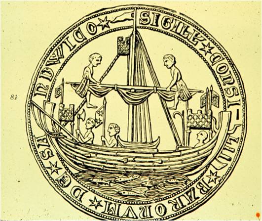
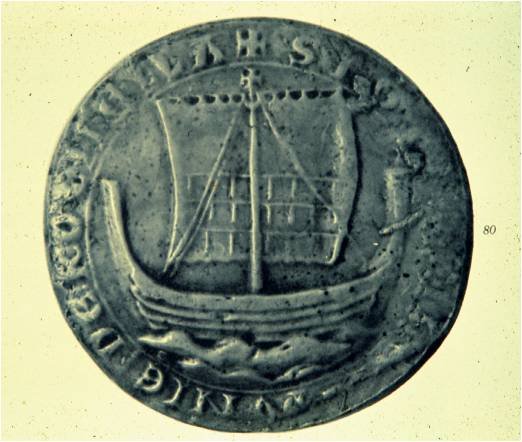
I've bookmarked this - it will be interesting to see more as the archaeological reports come in. This is really later than "Viking" times - just before "nefs" with castles in bow and stern, and I'd like to see what if any evolution can be seen from the intervening centuries. This is the seal of the coastal town of Sandwich, from 1238, which is about as early as these castles seem to have come into use. The 1188 ship is more likely to have looked like this: which is almost identical to Viking vessels. The differences are likely to be in the details, and the fact that this was a merchant ship not a warship. Steven
-
Very interesting. I look forward to hearing more about this one. Built about thirty years later than Mary Rose, but very close in time to Mary Rose's rebuild in 1536. It will be interesting to compare the two. Steven
-
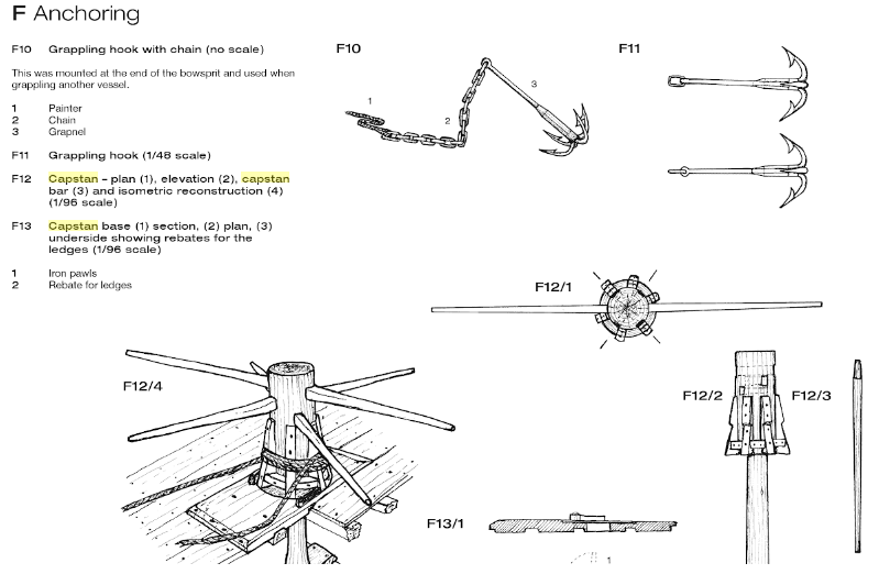
 The capstan of the Genoese ship Lomellina, built in 1503, has slots for two bars,each of which passes right through the capstan. The slots are at different heights above the deck. A reconstruction of the Mary Rose's capstan (with removable bars) is shown below. This seems identical to the one Patrick is making. This illustration can be found at https://books.google.com.au/books?id=MSCGCgAAQBAJ&pg=PA108&lpg=PA108&dq=mary+rose+capstan&source=bl&ots=EjQXJE-eU7&sig=ACfU3U3vIvX3cjv7dF9GZQA9g-OfSPourA&hl=en&sa=X&ved=2ahUKEwiCyu2auM_hAhWJfysKHUzvC70Q6AEwEXoECAgQAQ#v=onepage&q=mary rose capstan&f=false It seems unlikely to me that a capstan, even as early as the 16th century, would have its bars permanently in place getting in the way. Steven
- 756 replies
-
- 7
-

-
- galleon
- golden hind
- (and 2 more)
-
A very nice exposition of how Venice came to have such a wide-ranging Empire. The only thing I'd add is that Venice, having helped destroy Europe's bulwark against the expanding influence of the Ottoman Turks, lost its own "Empire" to them in the following centuries. Poetic justice? Steven
- 263 replies
-
- 4
-
-
- nave tonda
- round ship
- (and 2 more)
-
I have a very fond memory (and a photo) of sitting in the cockpit of a Mark IX under reconstruction (if that's the right word) about 30 years ago. It wasn't in running order, let alone flying order, but it's very nice to be able to say I once sat in a Spitfire. Steven
-
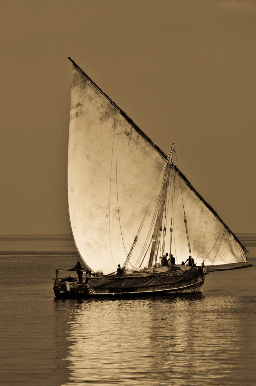
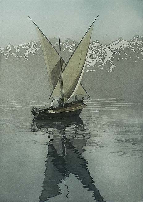
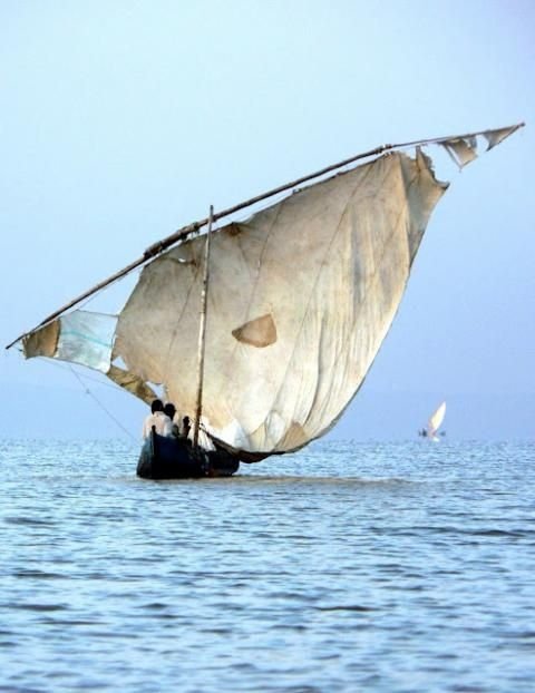
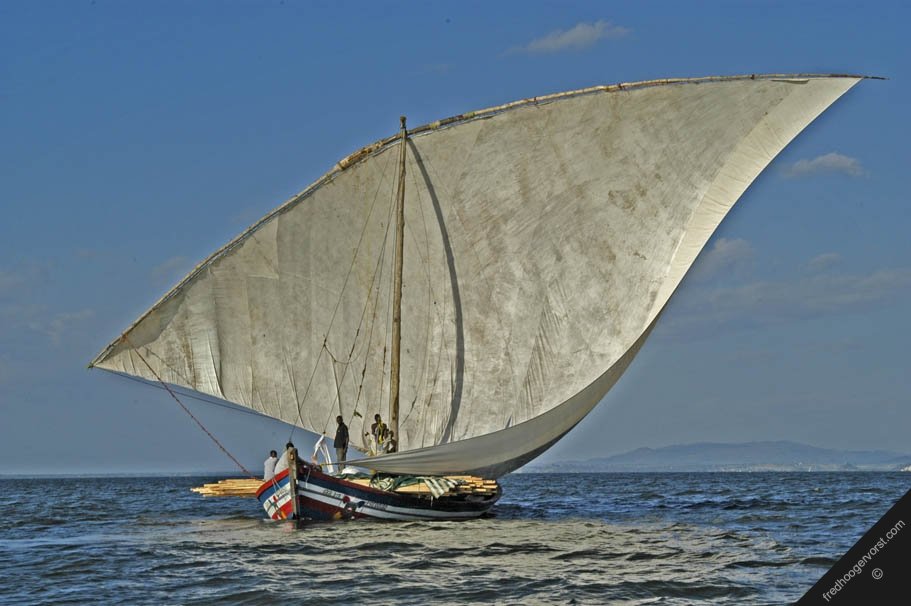
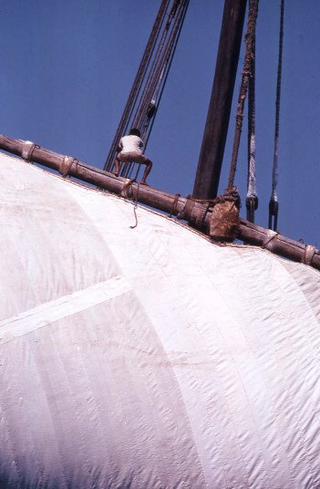
Dick, I'm inclining the same way. My masts are simple poles, as I haven't seen anything in contemporary Byzantine pictures to suggest they were built-up (not that this is any kind of proof - but it's all I've got to go on). By the way, I hadn't previously noticed that the mast in the left hand picture in your post seems to be made out of a barber's pole! Again, I agree. However, though the dhows are 19th century I think there's a fair chance they are "traditional" and have changed less than Western European examples. And I'll be using the simplest and arguably most "primitive" examples as a model to work from, on the basis that they're likely to be closer to mediaeval practice than any others.
-
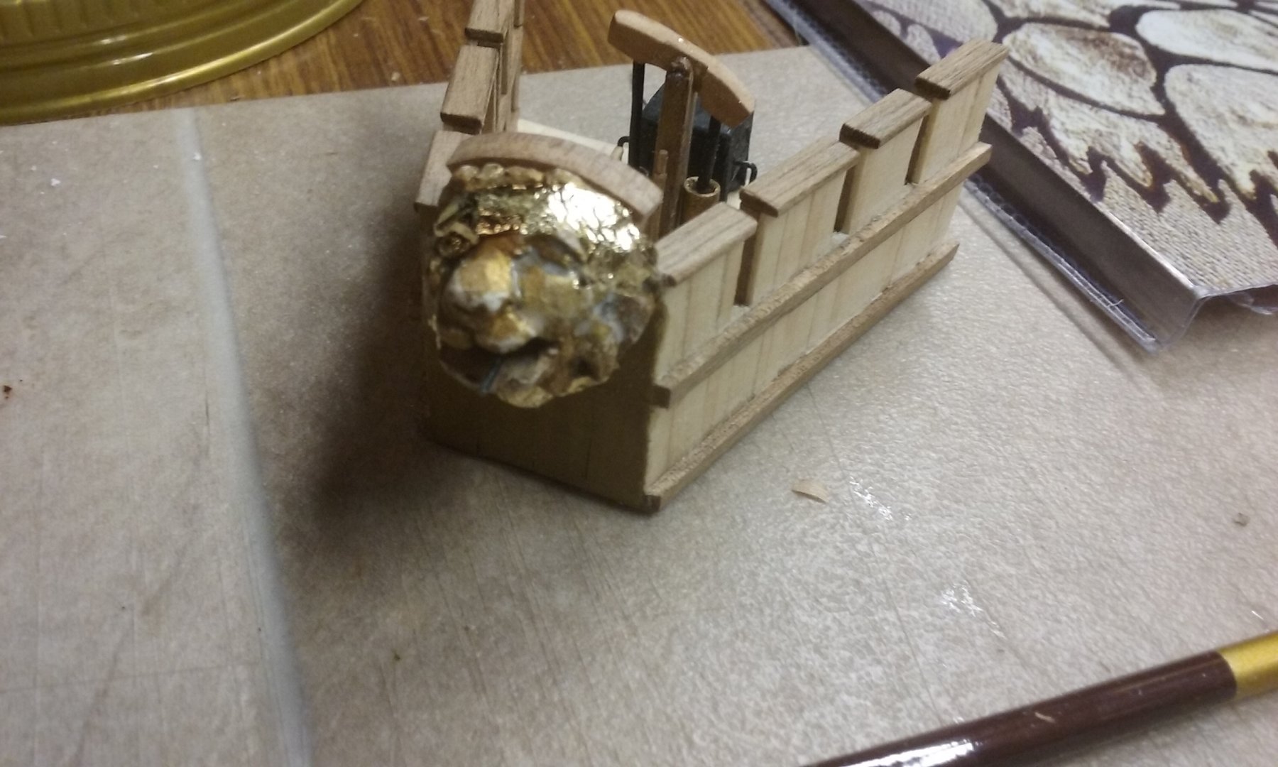
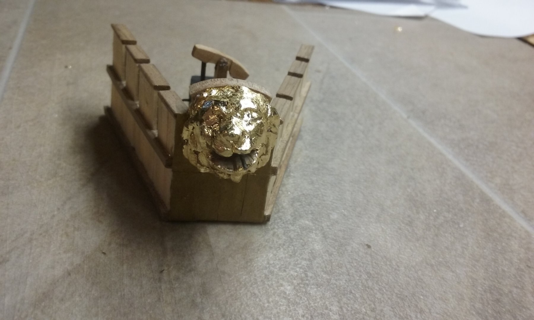
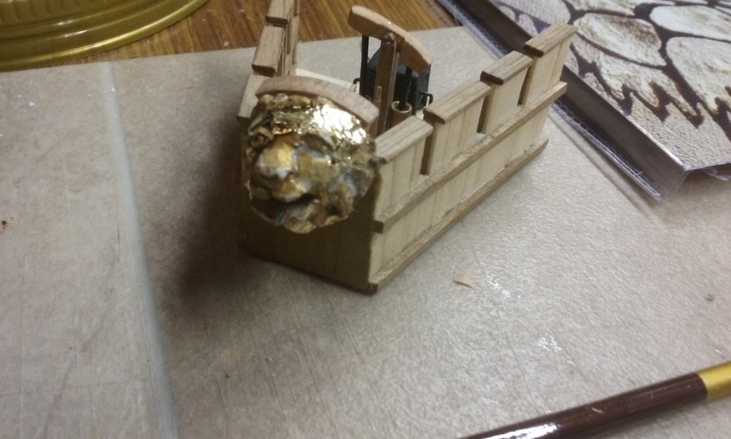
That's right, Carl. A very small brush indeed. Usually used for fine detail work. And after the glue was dry (I used dilute PVA) I buffed the exposed surfaces with the end of my finger. Here is perhaps a better idea of what the lion's head will look like when it's in place: Steven
-
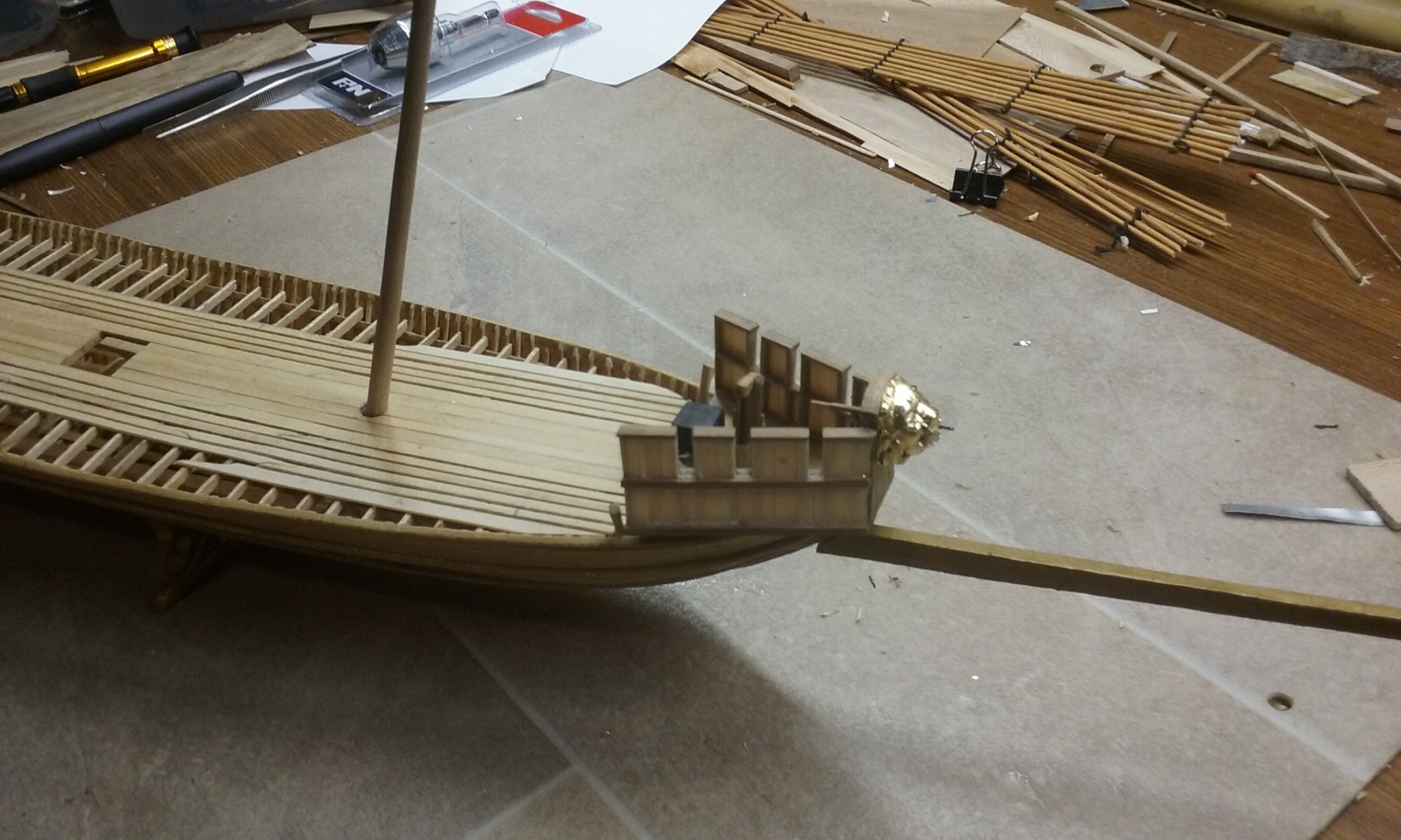
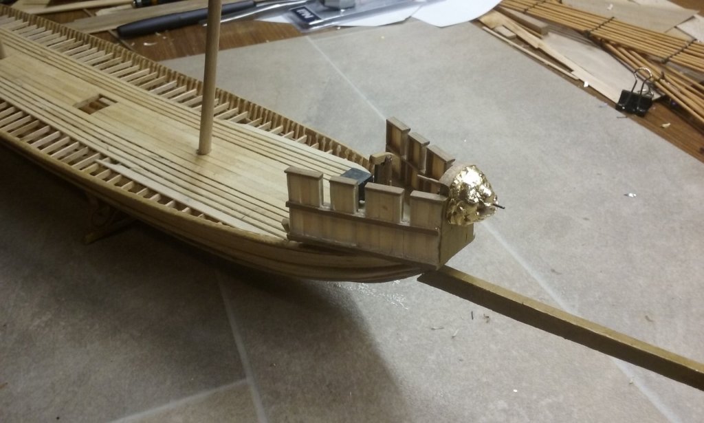
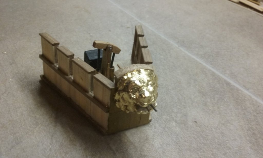
I've painted the "heat shield" at the front of the forecastle to look like bronze plating, and covered the lion's head with gold leaf, in line with the description in the Alexiad. The photos don't really give a good impression of just how shiny it is. Just starting out: And completed: A lot of very fiddly work and a certain amount of cursing. But I feel more confident now that I can put gold leaf on things fairly well. Still a lot to learn but not quite as terrified of getting it wrong as I was before. Steven

-
Thanks Alberto. I've seen that counterweight on dhow photos and wondered what it was. Another mystery cleared up. All this info should give me a good basis for the rigging for my own dromon. Steven PS: The Castle is really worth seeing if you ever get a chance to get hold of it. See https://www.google.com/search?q=the+castle+movie&rlz=1C1NHXL_enAU770AU770&oq=the+castle+&aqs=chrome.5.69i57j69i65j69i61j0l3.5590j0j7&sourceid=chrome&ie=UTF-8 for some highlights.
-
Nice precise work. Looking good. Steven
-
Thanks for all the likes. And thanks to Christos and to Binho. Christos, there are so many possible interpretations of what a dromon would have looked like based on the rather limited information available from contemporary documents (usually only mentioning dromons in passing) and pictures (usually grossly oversimplified), and the archaeological record. I still think Pryor's is the best interpretation based on the information available at the time he published and my model is mainly based on that, but with changes based on the Yenikapi finds plus some from my own interpretations of the pictorial record and also practicality. Binho, that's an AMAZING site and it probably answers every question I've had. To be honest, I think this information would be an eye-opener to most people (with a few notable exceptions) on this forum. Lateen rig is rather the poor relation in modelling compared to square, and this site is a real resource. The other thing is that it contains some very good pictures of the vessels themselves - a very worthwhile resource for anyone interested in this kind of craft. Thanks very much for posting this site. It's going straight to the pool room (Aussie joke - if you've ever seen the movie The Castle). Steven
-
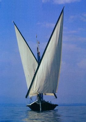
Thanks everyone for the likes and thanks particularly to Dick, Christos and Mark. Dick, thanks for the advice on trusses. I'm really a babe in the woods regarding this stuff and very much feeling my way. I'd been thinking of having the halyard blocks behind the mast with the tackle running aft to the deck. Which is why I've so far been thinking of having the calcet sheaves running fore and aft. Christos, you're welcome to add stuff. Sometimes such things can lead to new insights which would otherwise not have happened. I don't agree with everything about this interpretation, but I find their treatment of the forecastle in particular very interesting. Mark, if the yards are most of the time across the hull, I expect the fore and aft calcet would work best. Having now seen quite a few photos and a fair bit of footage of lateeners under sail, the yard is often crosswise, and often almost horizontal rather than angled, something you never seem to see in the reconstruction pictures, but which seems to come up a fair bit in contemporary pictures, which rather reinforces the idea that they may be accurate representations. Gotta love the patchwork sail on the last one . . . Here's the kind of thing I'm thinking of when a two-masted dromon is before the wind. I don't know about anyone else, but this goosewinging of the sails really appeals to me. Steven
-
Well, actually there was a regular Viking trade route down the rivers of Russia to Constantinople, and the Vikings of Russia sailed south to attack the City at least once (fleet destroyed by Greek Fire). Also, Harald Hardrada did a fair bit of sailing around the mediterranean working for the Byzantines. BUT . . . Viking ships in the Mediterranean? Not sure. Harald would have been sailing in Byzantine ships, and the trading vessels may not have got south of Constantinople. On the other hand there was at least one Viking fleet that came through the Straits of Gibraltar and roamed and raided around the Med. But the Minoan galley sounds really interesting. Steven
- 73 replies
-
- 2
-
-
- mediterranean
- galley
- (and 1 more)
-
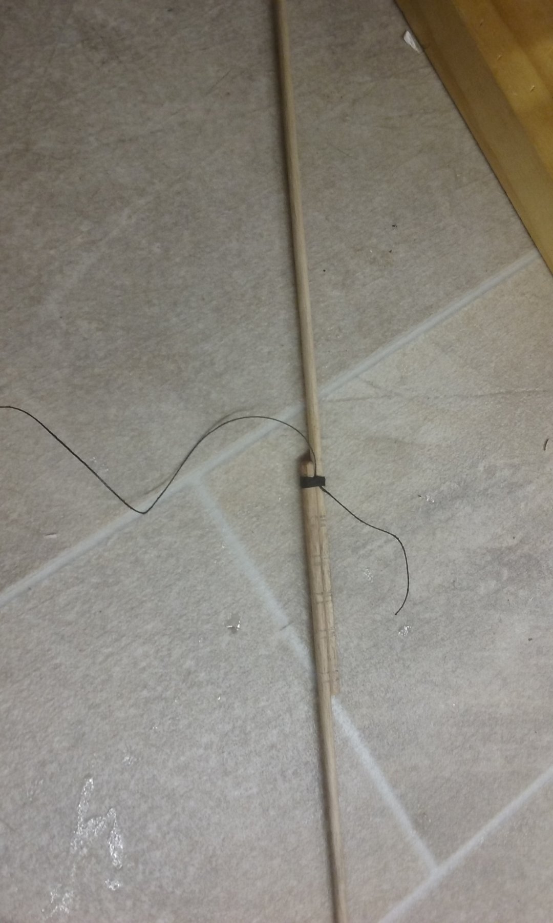
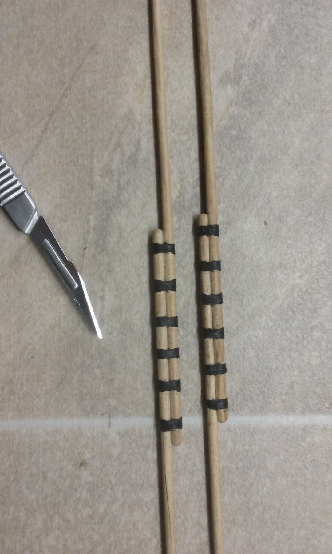
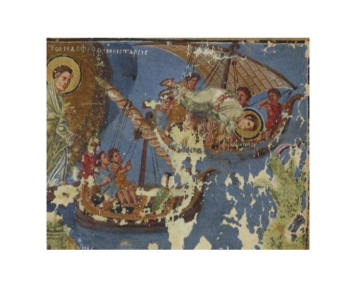
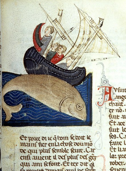
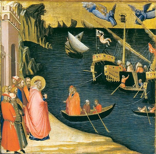
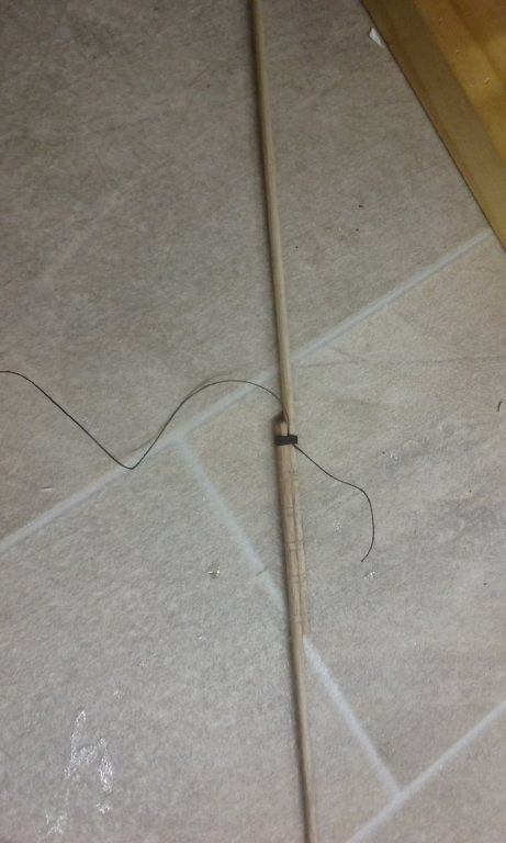
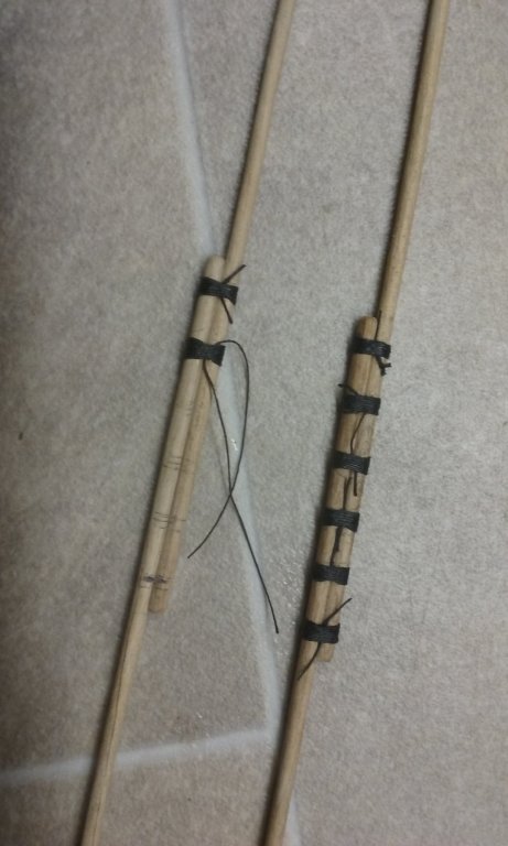
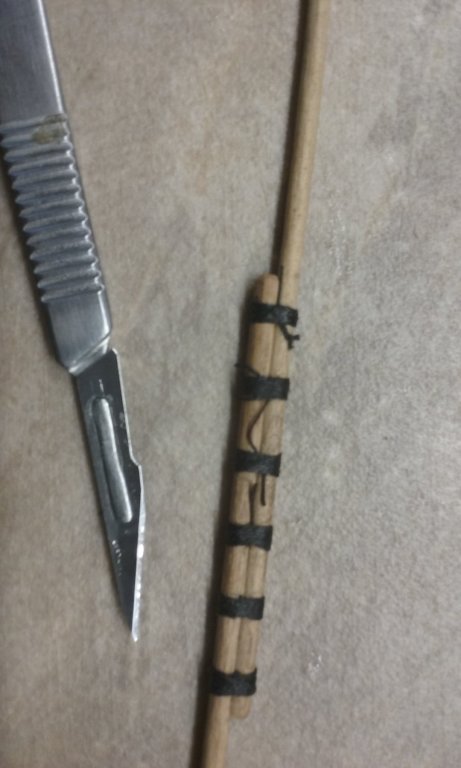
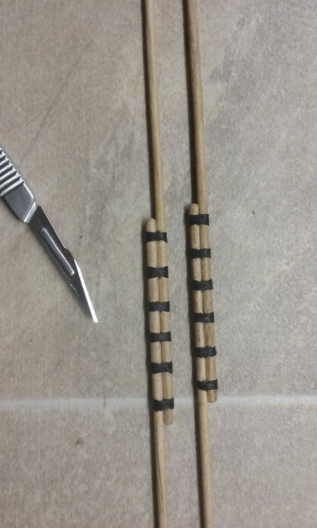
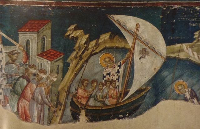
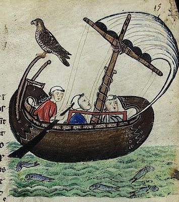
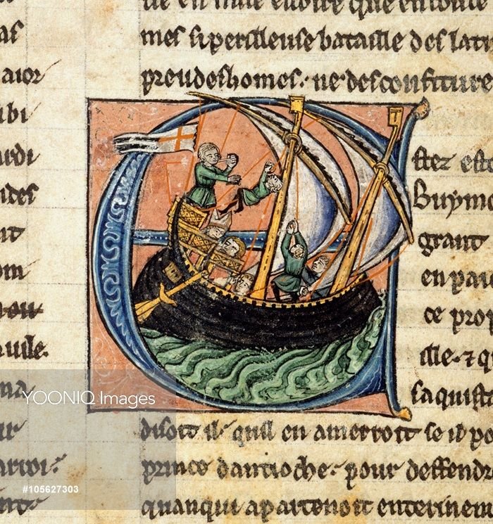
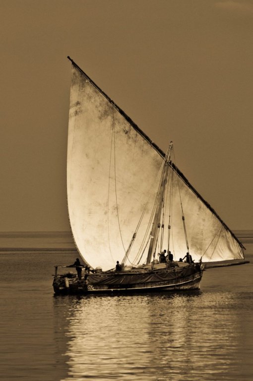
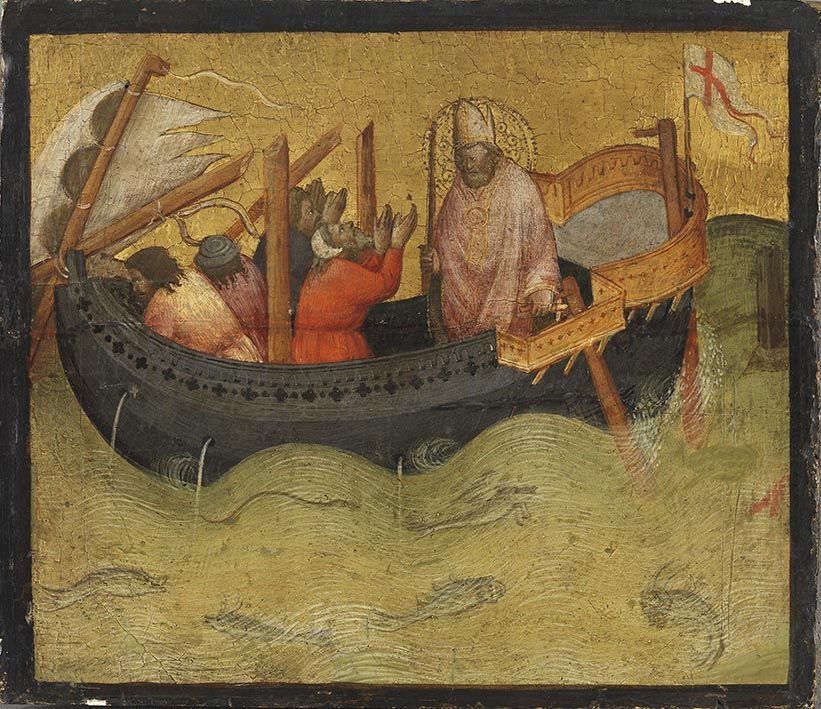
I've finished the lashings on the lateen yards. Done with the same technique used for whipping a rope's end and then glued. Loose ends cut off with a scalpel. Next I have to work out exactly how to support these yards on the mast. A halyard through the calcet - but should the calcet be abeam (as Prof John Pryor states) or fore and aft (as this picture of Saint Nicholas seems to suggest? And should the halyard simply wrap around the yard, or support it in two places to improve its balance? And then there's the "truss" holding the yard to the mast once raised. Saint Nick has nothing at all, and most if not all other Byzantine pictures are just as bad. Later mediaeval (Western Mediterranean) pictures sometimes show something that appears to simply be a loop around the mast, as is shown in this 14th century picture Or this Byzantine one (date unknown) Or something a little more complex, as in this from the late 13th century. However, most mediaeval pictures just leave these details out. Modern Mediterranean pictures aren't all that helpful - mainly because they are modern, and of much smaller vessels. So I've looked at photos of dhows still sailing under traditional lateen rig - at least they were when the photos were taken in the 20th century. I'd probably be able to get away with a simple loop, but I'm not sure it would be secure. If anybody has any ideas or suggestions I'd appreciate it. Steven
-
I hope so, Pat. I'm very aware of the shortcomings, not only of the original, but of my rather bodgy repairs. But I suppose it's just a matter of keeping on with it and hoping it'll be alright on the night . . .😒 Steven
- 740 replies
-
- 3
-
-
- Tudor
- restoration
- (and 4 more)
-
I love Ringerike style. When I was doing Anglo-Saxon re-enactment I engraved the nose-guard of my helmet with a Ringerike design (which was also common in England in the mid-late 11th century). Looks like it's probably time to make a new keel. Less work and grief than trying over and over to fix something that doesn't seem to want to be fixed. The important thing is to choose a piece of wood that has straight grain in the first place. I had the same problem with the foremast of my dromon. I found it easier to just start again than try to fix it. Steven
-
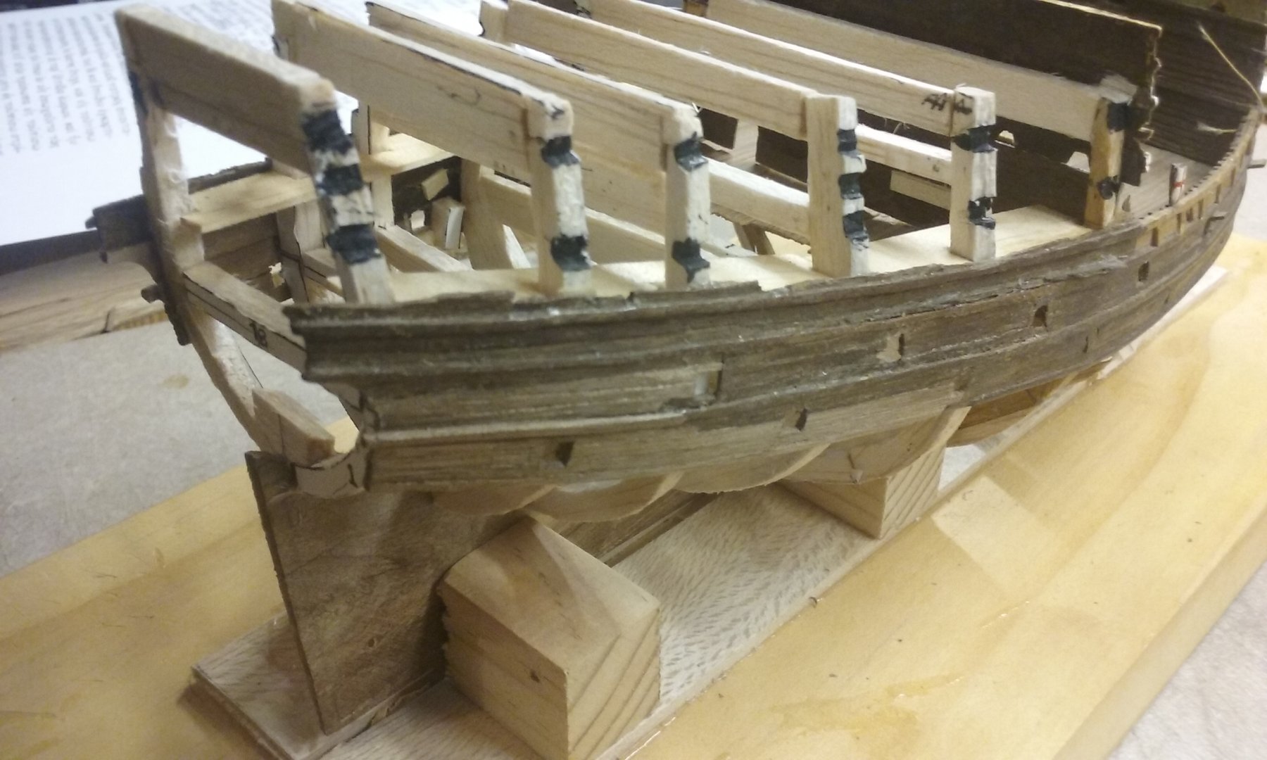
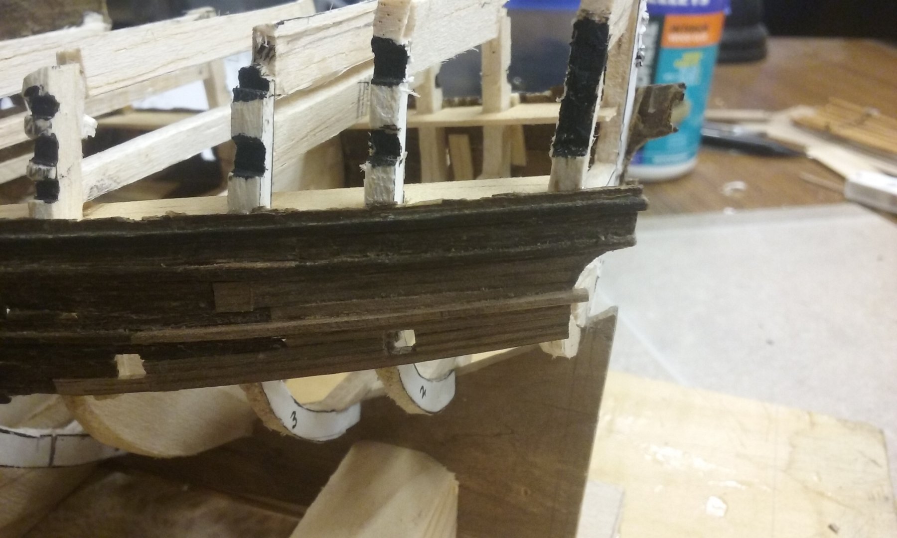
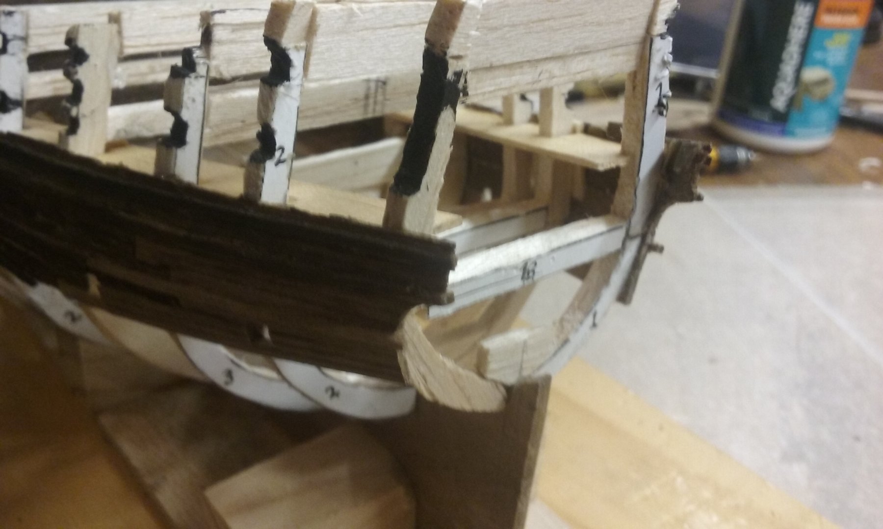
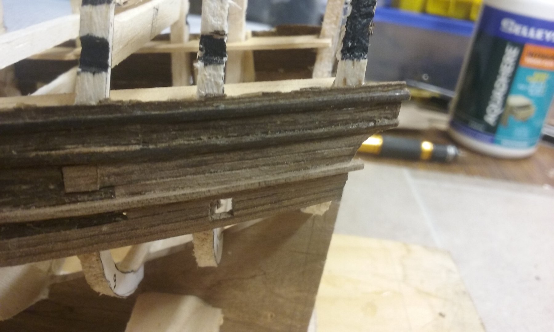
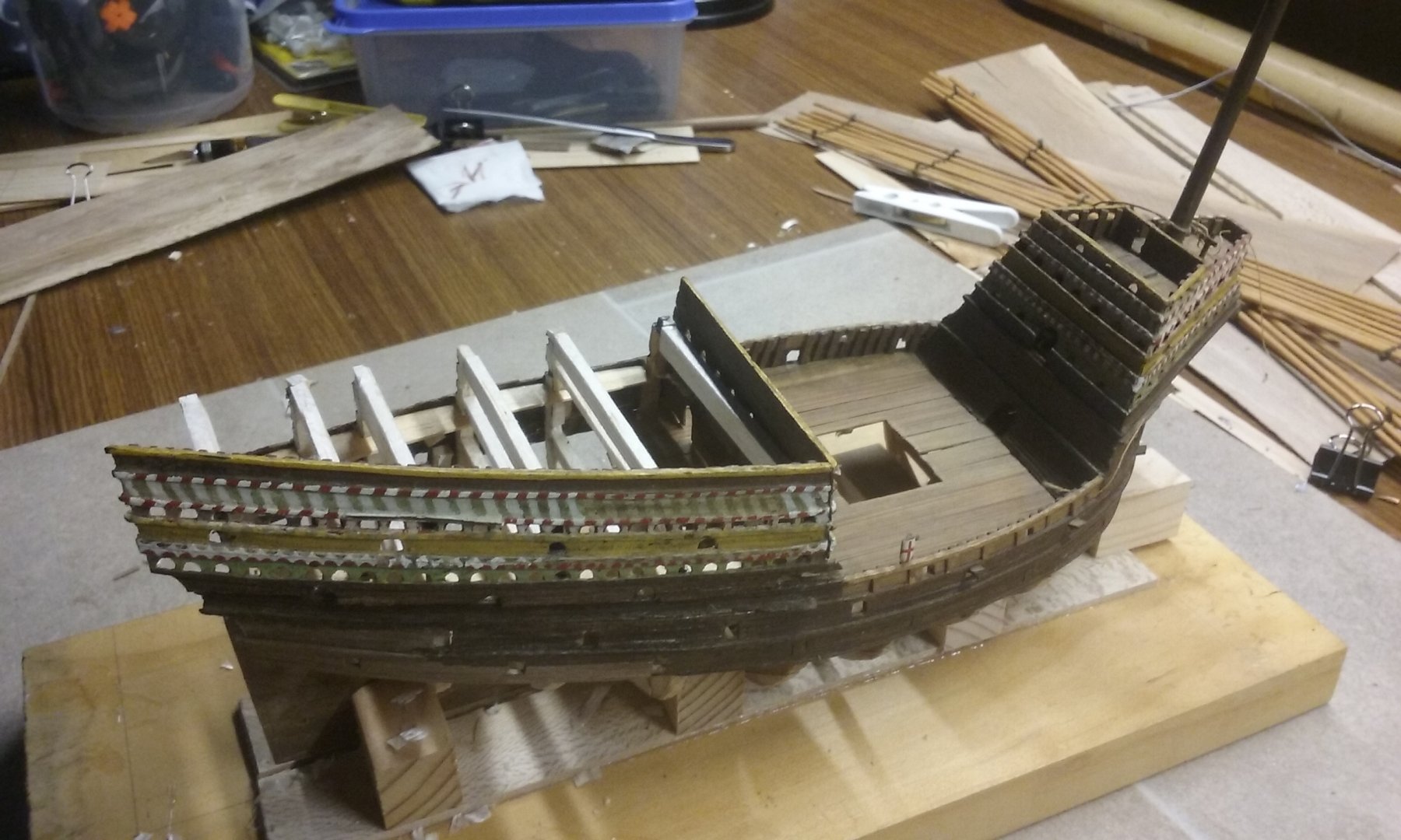
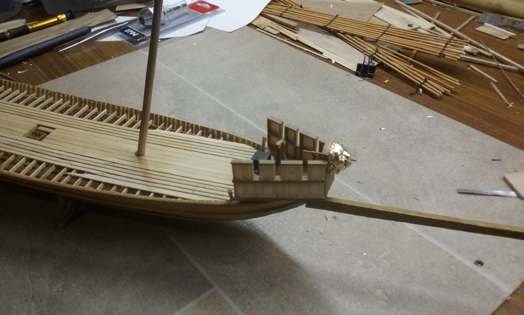
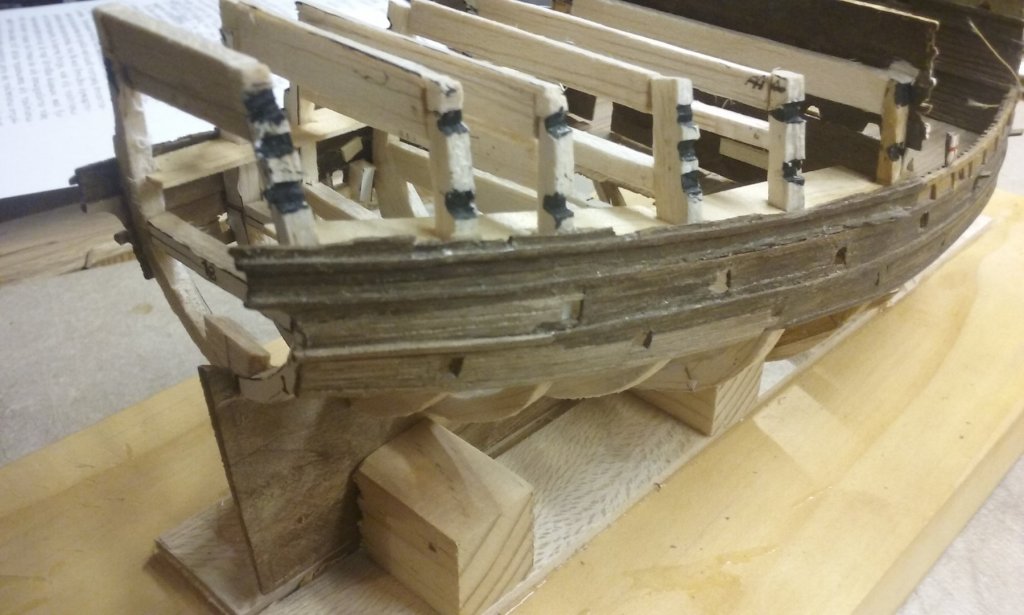
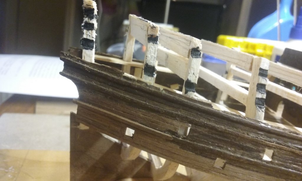
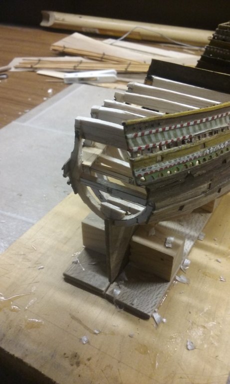
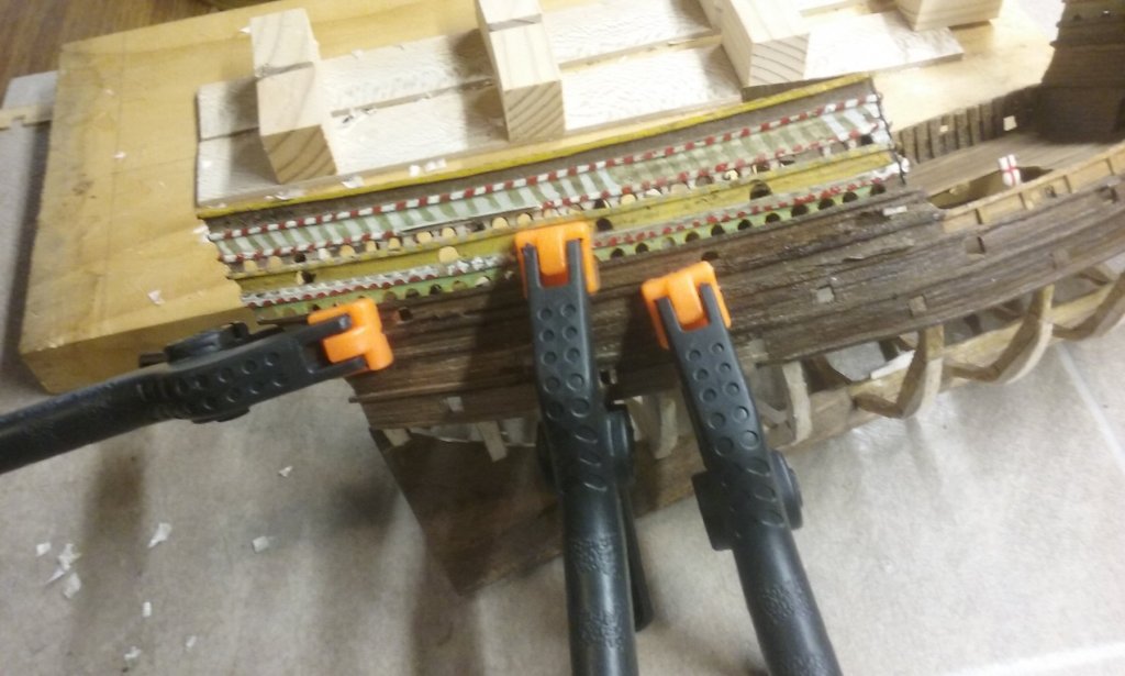
Trimmed the new panels of planking to shape at the stern, added the missing pieces to the broken wales and cut gunports I've also trimmed the deck beams so they tie in with the bottoms of the false "frames" that show above the top deck, so I can fit the decking in below them. And something of a milestone, I've finally glued one of the superstructure panels back into place, after being off the ship for a long time. Because the stern is narrower, the old aftercastle panels don't quite fit on top of the old hull planking - I'll have to do a little adjusting to get everything together and fill up any gaps between the two. That's all for now. I really should get back to the dromon. It's been sitting there neglected for a while. Steven


- 740 replies
-
- 8
-
-
- Tudor
- restoration
- (and 4 more)
-
Use the search function at the top right of this page and put in the words "straighten" and "keel". You'll get a lot of hits (including your own build!). I remember seeing something some time ago that water doesn't do anything in straightening wood - it needs heat, which makes the fibres more supple and stretchable. A hair dryer or heat gun supplies enough heat for the job. But you should be able to find something worthwhile with a bit of a search through these posts. Looks good! Are you doing a figurehead? (Note: NO Viking ship has been found with its figurehead, but there are a goodly number of Viking carved posts with dragon heads on them, which can be used as a basis. The one in the CG model is an invented one, certainly in a Viking style - late 11th century, actually - a style known as Urnes, after the church where it was first recorded. I did a Google image search on " archaeology viking dragon heads" and came up with a lot of pictures, including the best examples. But a caution - even with this wording quite a few images came up that as far as I know aren't based on any actual Viking finds.) Keep at it - the problems you've encountered can be overcome, and perhaps it's a blessing in disguise to have gone through all this. What doesn't kill us makes us strong . . . Steven
-
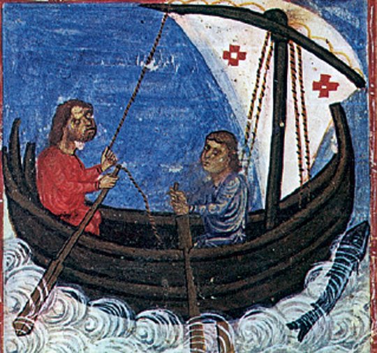
Hope I'm in time to add this picture which might be of help - It's by Agnolo Gaddi of Florence, dated 1393-96, and depicts one of St Nicholas' miracles - saving a ship by calming a storm. Some very interesting details. And now a little joke for those who know a bit about the original Saint Nicholas . . . Steven
- 263 replies
-
- 4
-
-
- nave tonda
- round ship
- (and 2 more)
-
How are sails fixed to yards?
Louie da fly replied to Louie da fly's topic in Masting, rigging and sails
Thanks again, everyone. Very much appreciated. Steven