Louie da fly
-
Posts
7,973 -
Joined
-
Last visited
Content Type
Profiles
Forums
Gallery
Events
Everything posted by Louie da fly
-
 Looking really good, John. On the third photo above, the transom looks a little out of square, but I expect that's just a trick of the photograph angle. Steven
 -
Beautiful work, Dan. And fascinating following your analysis and reconstruction of the complex details of this section of the superstructure. Captain Hartley isn't based on the Fat Controller, by any chance? Nah, can't be. Wrong hat . . . Steven
- 238 replies
-
- 5
-

-
- leviathan
- troop ship
- (and 2 more)
-
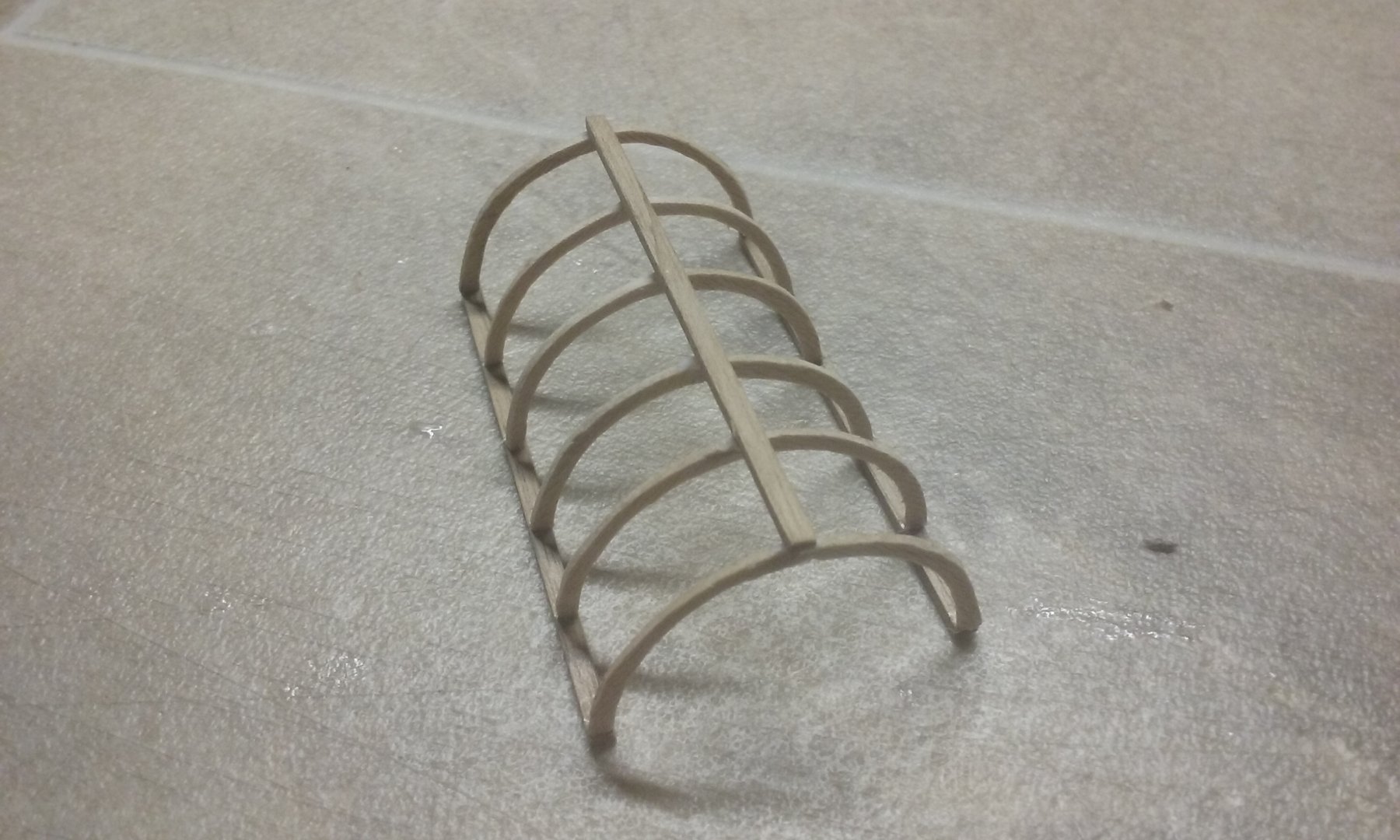
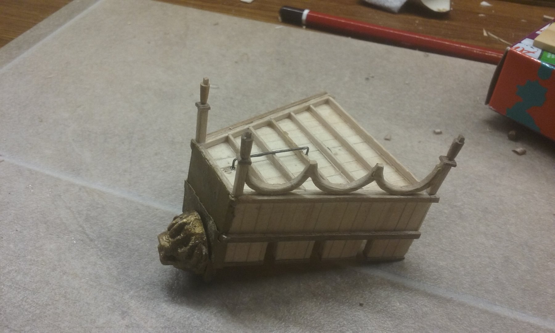
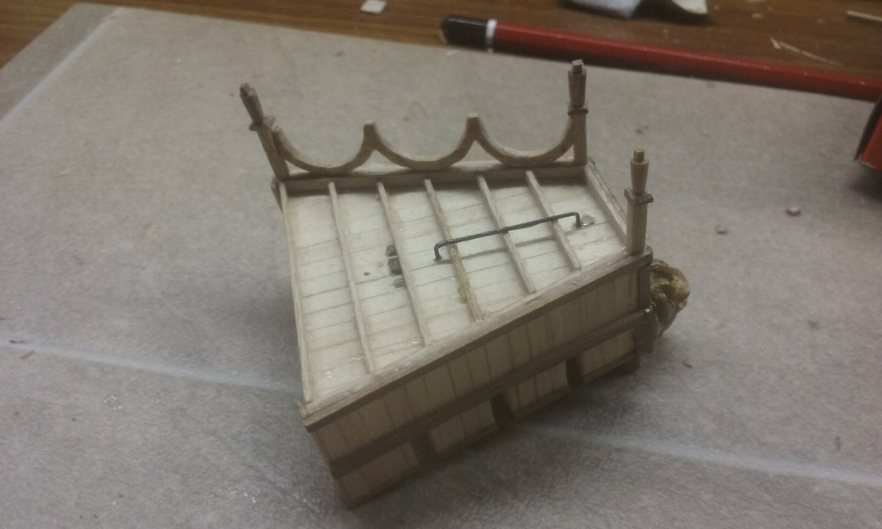
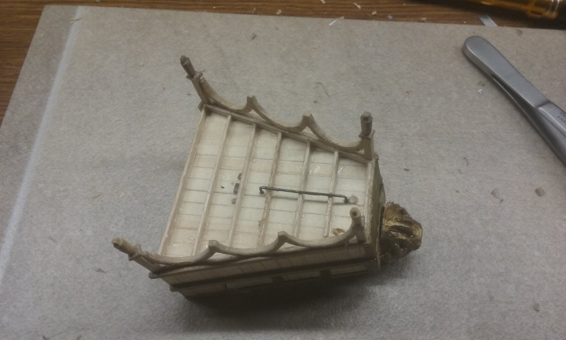
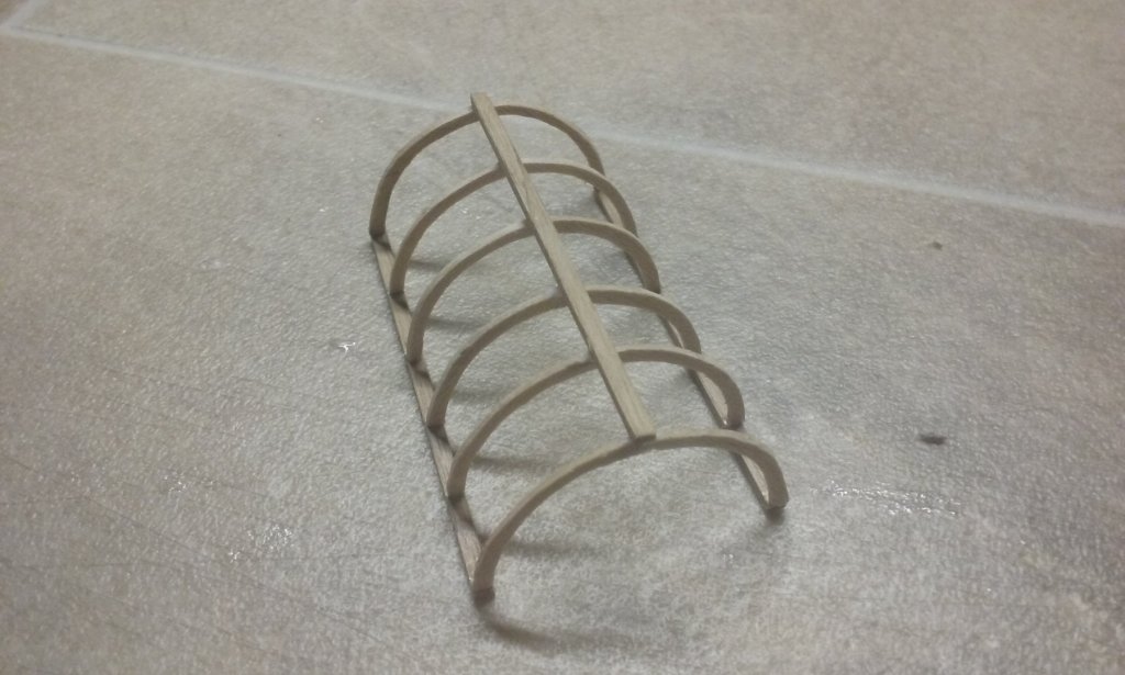
Forecastle complete except for intermediate columns, which will be added once it's in place on the ship. Arches for poop deck awning Framework done for awning. Support columns still to be made. Steven

-
Thanks Yancovitch - and yet, like you, I'm very aware of the faults in my own build that others don't seem to see . . .😉 Thanks Pat for the comments, and everybody for the likes. More to come. Steven
-
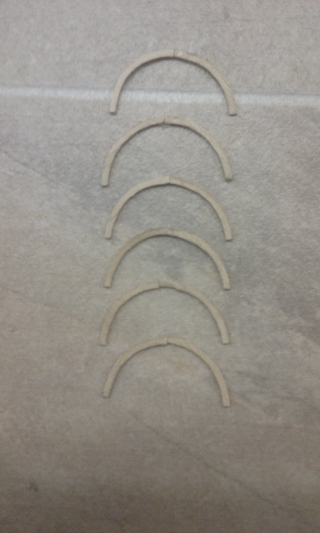
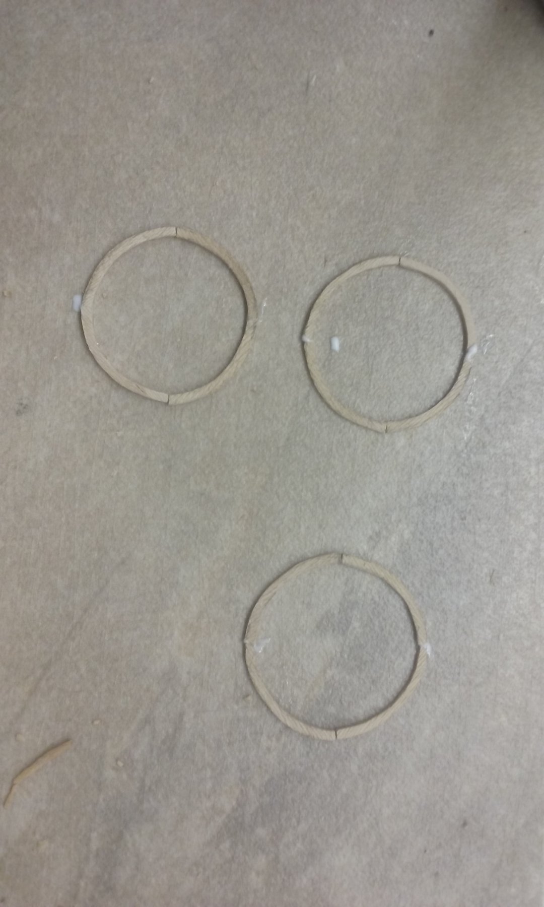
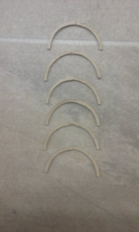
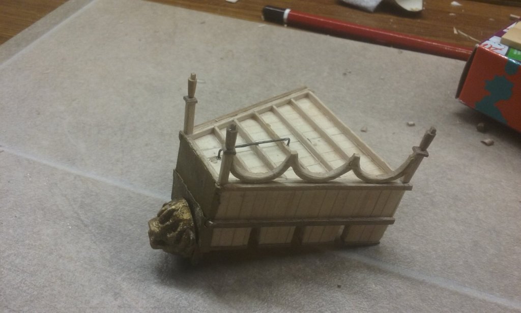
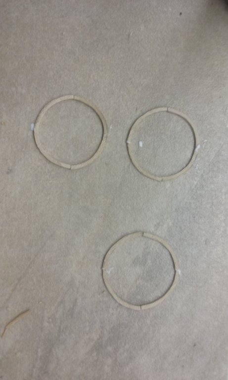
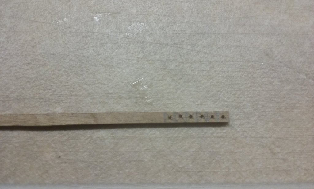
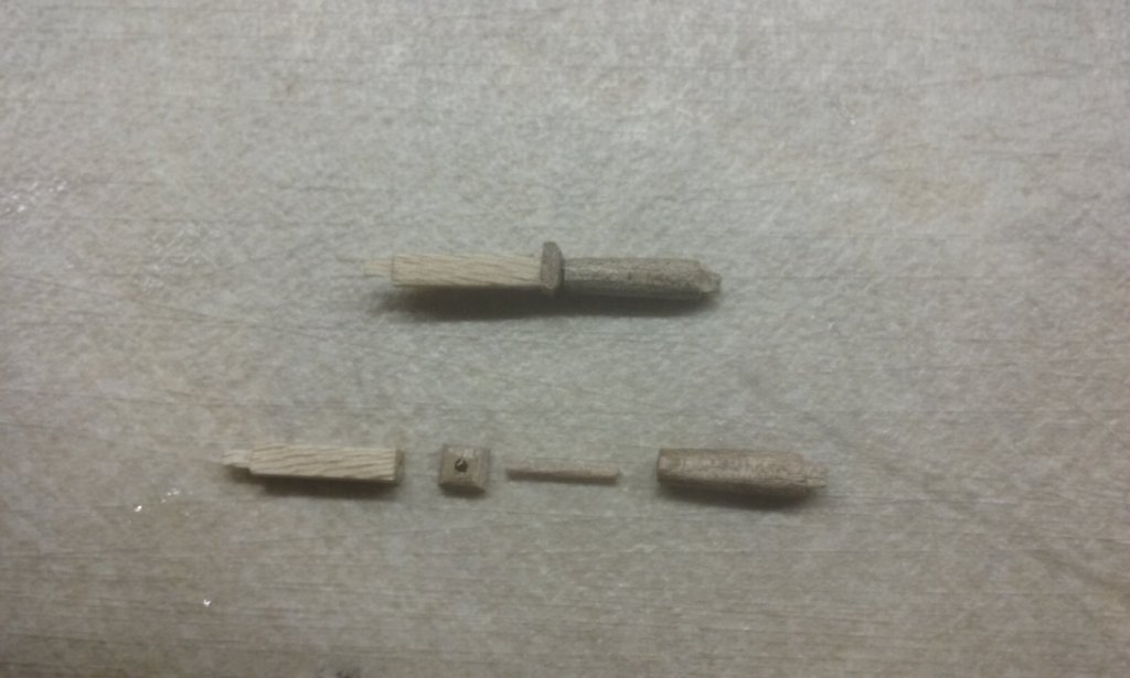
I've done the arcade substructure for the forecastle, incorporating lessons from my mistakes when I did the two side castles. The main things I'm doing different are leaving this bit till last as it's all rather delicate, and to fix the component parts with tenons or dowel joints, rather than rely on butt joints to keep everything in place. Here are the capitals for the columns below the arches. and the parts of the column/corner assembly - and the assembly - er - assembled Adding the first column/corner assembly and the arcades I won't be able to have tenons on the intermediate columns - there's note enough thickness in the arches, and I can't determine the locations of the bottoms precisely enough to put the mortises in place. So I'll be forced to put these in with butt joints, but that should be ok - they're subsidiary pieces and not truly structural. I've also made a start on the arches for the awning at the stern. Couldn't work out how to get a decent semicircle for each, until I thought - two of them make a circle, and a perfect/imperfect circle is much easier to spot than a perfect/imperfect semicircle. So I put six arches together in sets of two to form circles; much better. Steven


-
Beautiful work, Luponero. I am enjoying following this build. Naves of this time are of great interest to me. Steven
- 197 replies
-
- 2
-
-
- santa maria
- carrack
- (and 1 more)
-
I'm in the middle of a book called "War in a Stringbag" by the pilot who was the last to land on Glorious just before it was torpedoed and sunk, redeployed to Illustrious, took part in the Taranto raid, was in the air when Illustrious was heavily damaged by Stukas (which also tried to shoot him down) and had to fly to Malta to land, then the desert campaign and then Greece. That's as far as I've got so far, but fascinating reading. Steven
-
Thanks everybody for the likes. Christos, thanks for the comment. I wish I could speed it all up, but I have to fit it in with everything else I have to do, and it all takes time - more than I'd expected. The amount of time I've spent waiting for paint to dry, then glue to dry, you wouldn't believe!😁 Steven
-
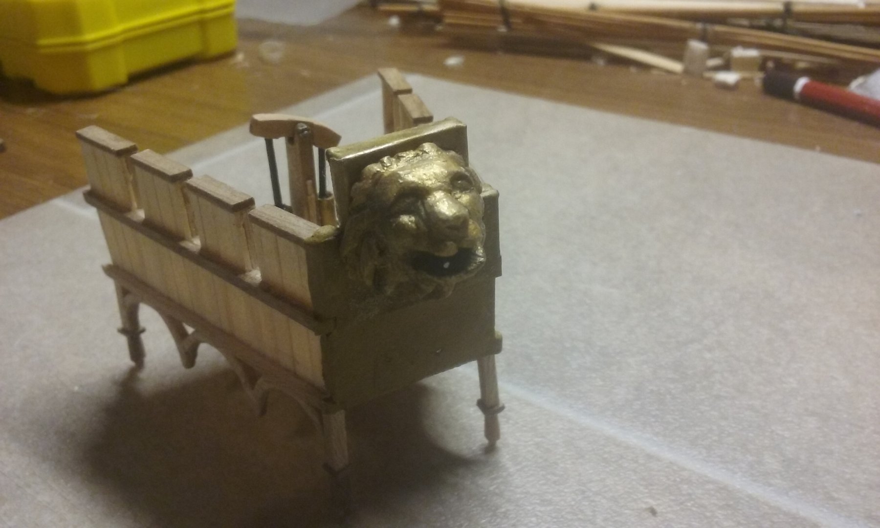
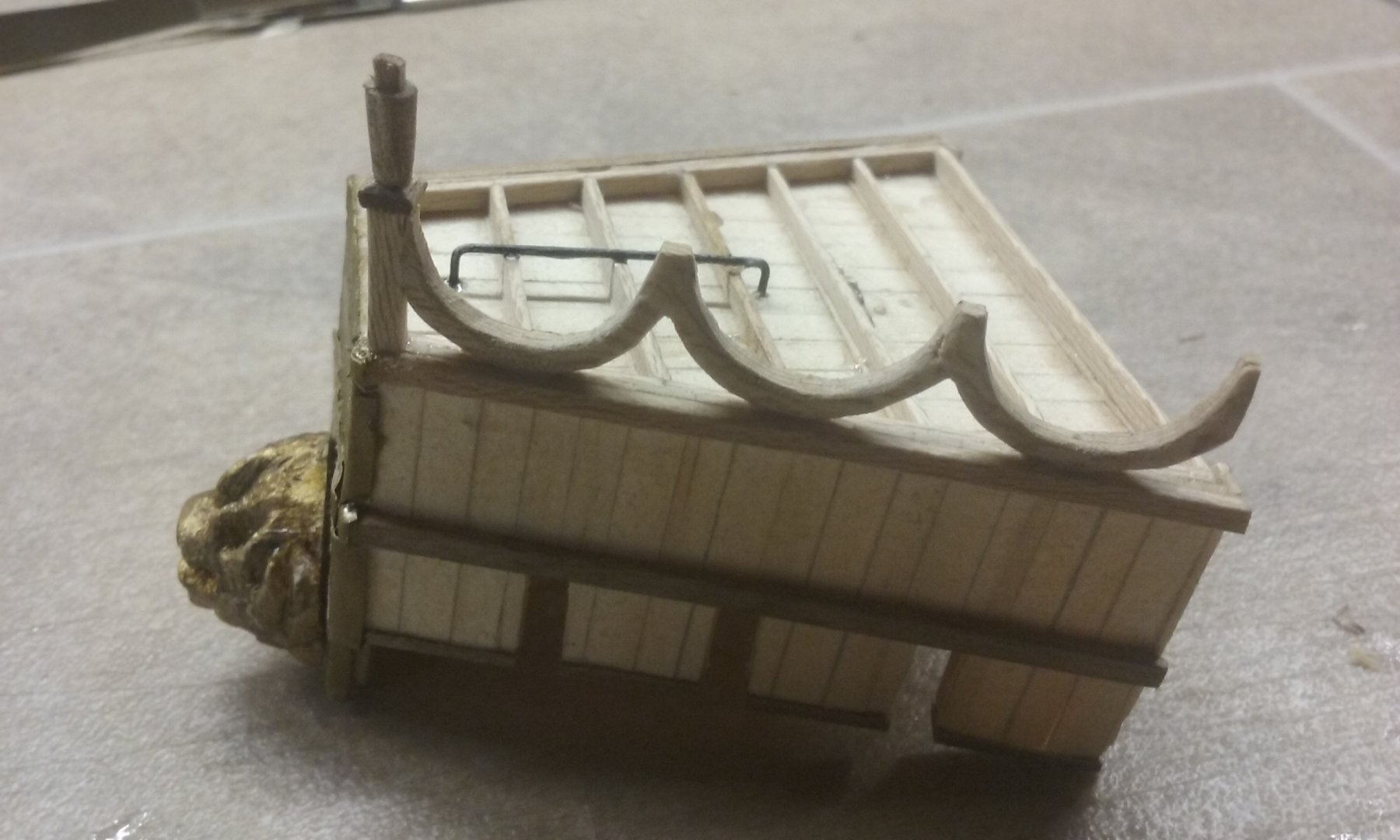
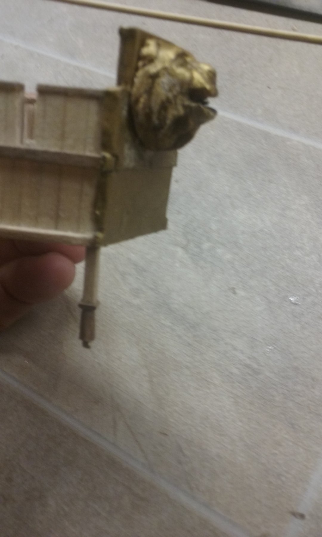
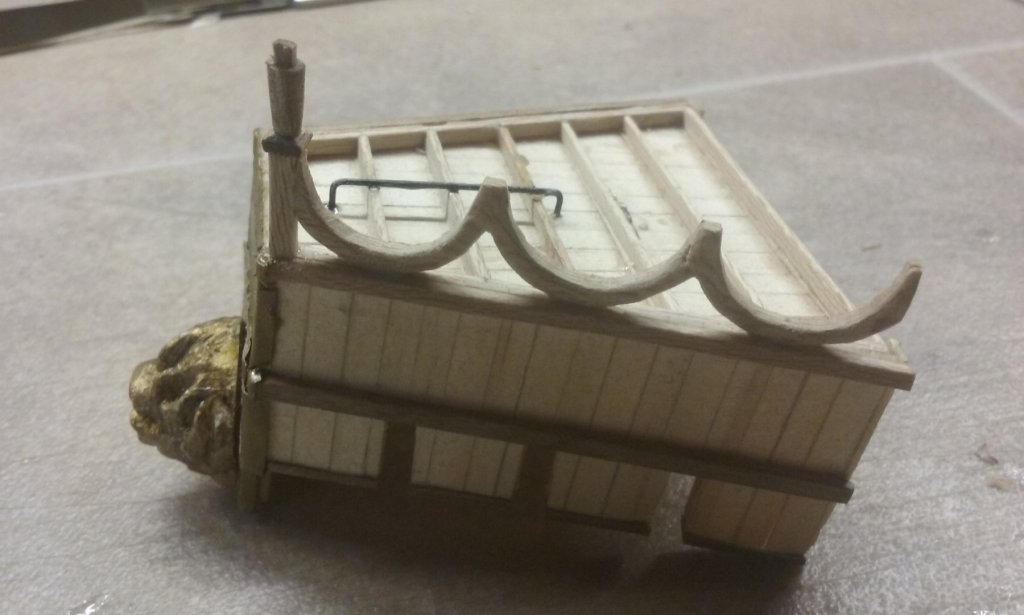
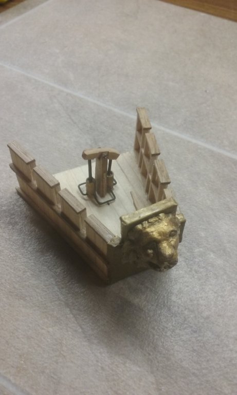
Just painted the "bronze" plates on the spur and the forecastle so they're the right colour. And added the "bronze" lion's head to the forecastle. Not too bad, but I'm sure I'll do better next time if I have to do something similar again. And installing the siphon on the forecastle is almost complete, with the nozzle passing through the lion's mouth. I've run a "pipe" under the deck between the pump and the riser. To finish the rest off I have to wait till I've finished the forecastle's arched substructure and the dry-fit the forecastle onto the ship, with the oil reservoir on the main deck below it, so I can install the "pipe" through the forecastle decking to connect the pump to the reservoir. Then it'll be ready to install (when I've done all the other things that need to be done to the ship before it goes in position). Making progress. Steven


-
Hmm, I might have been better cutting individual plates for the cladding and gluing them on separately. Steven
-
Thanks, Dick. Looking forward to seeing your interpretation in practice. Steven
- 263 replies
-
- 3
-
-
- nave tonda
- round ship
- (and 2 more)
-
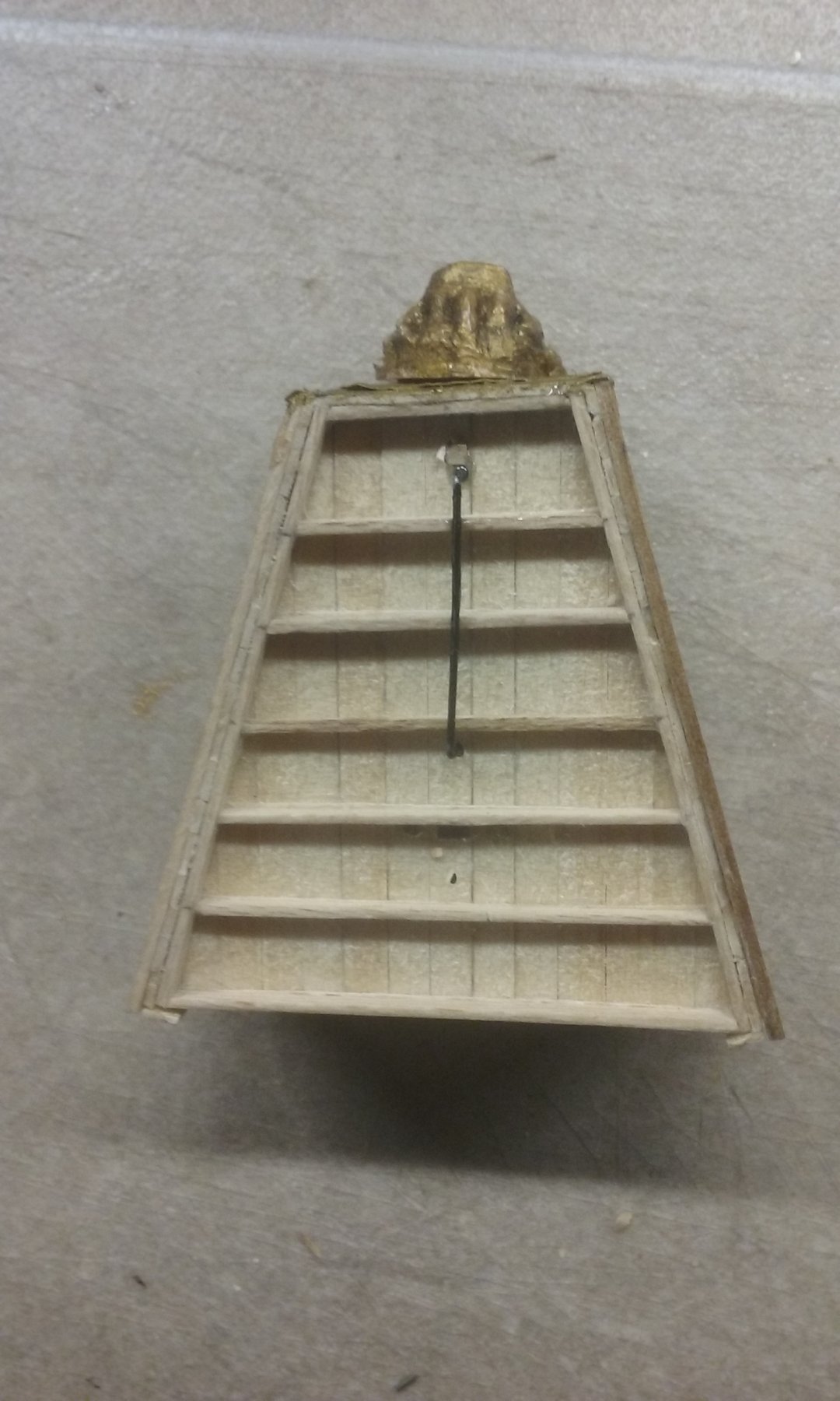
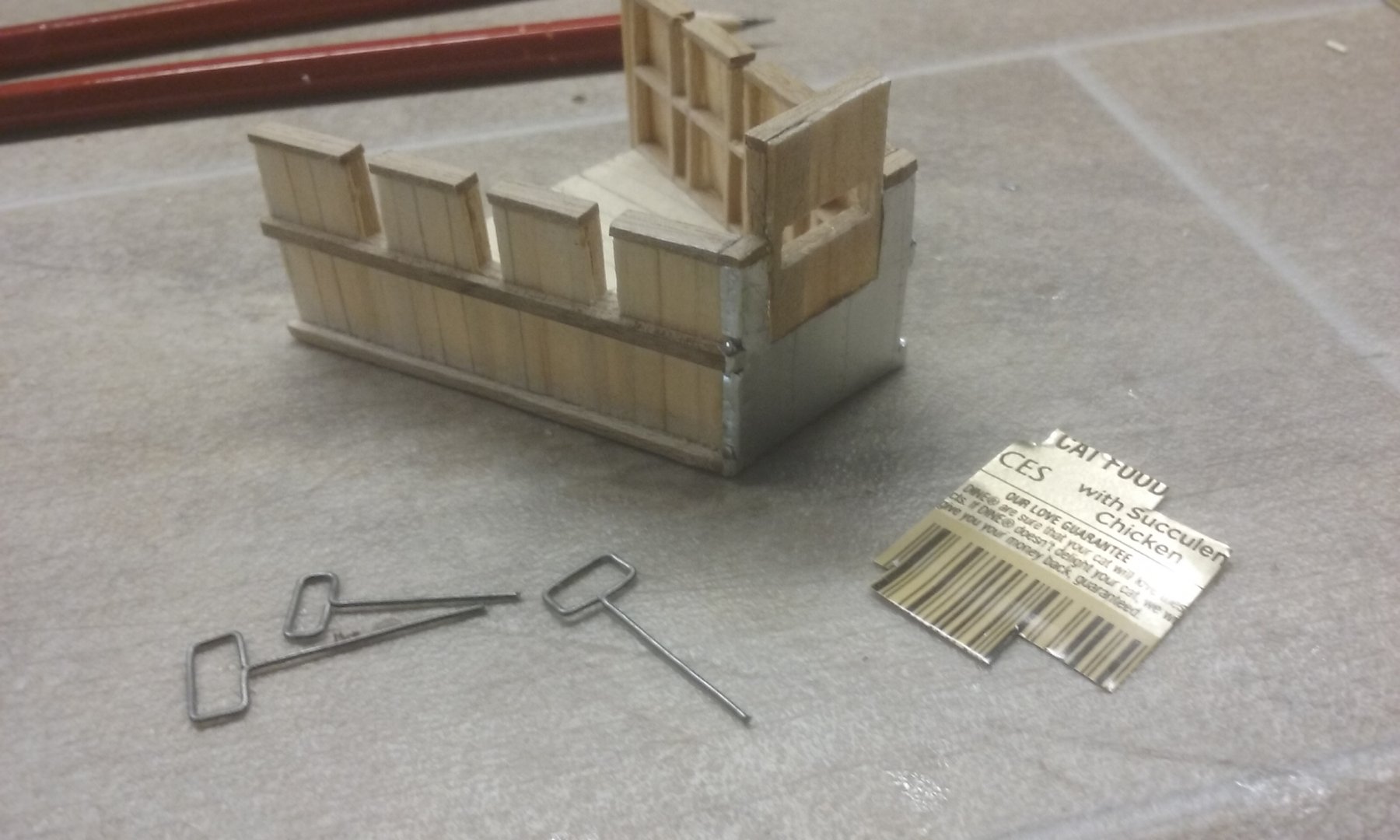
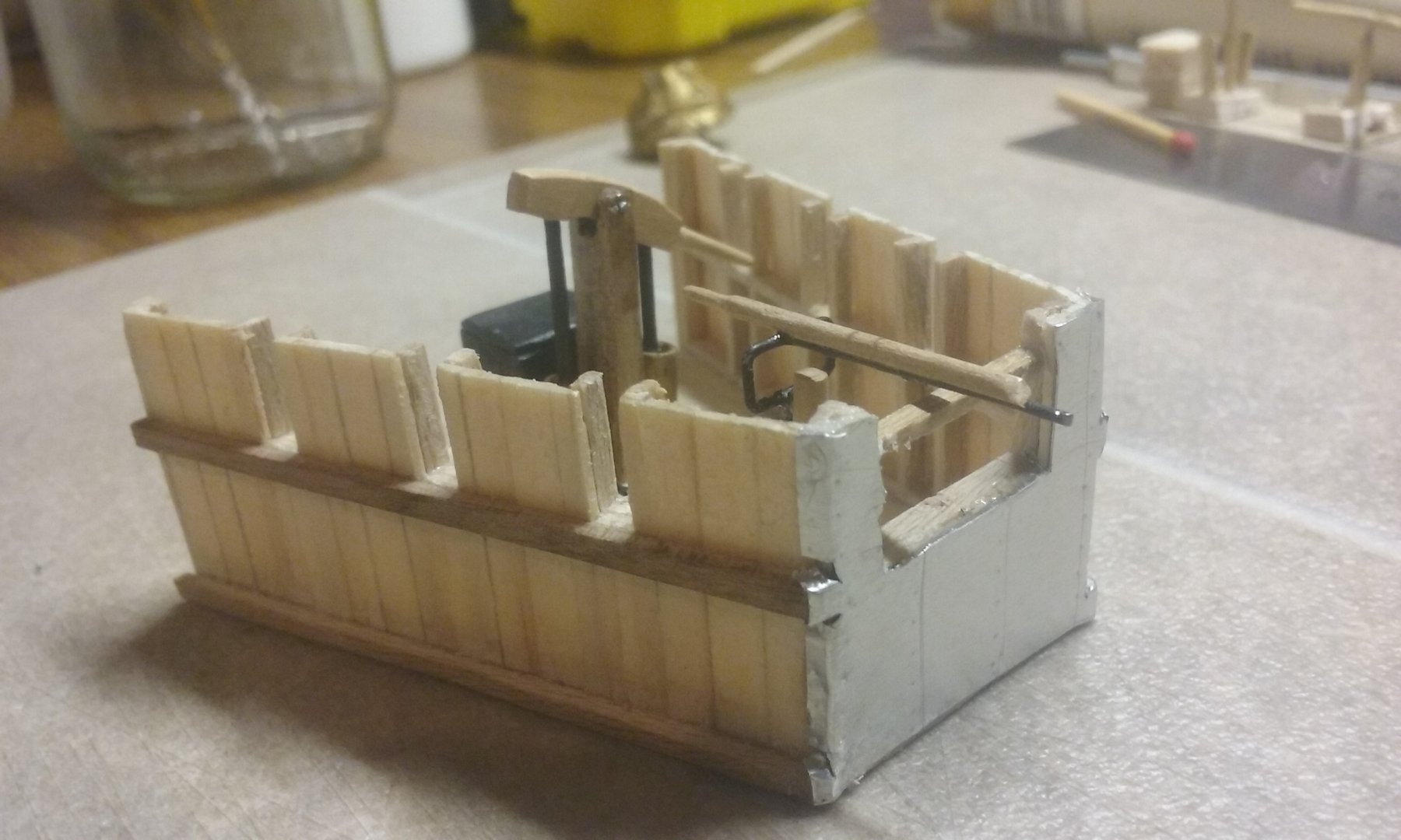
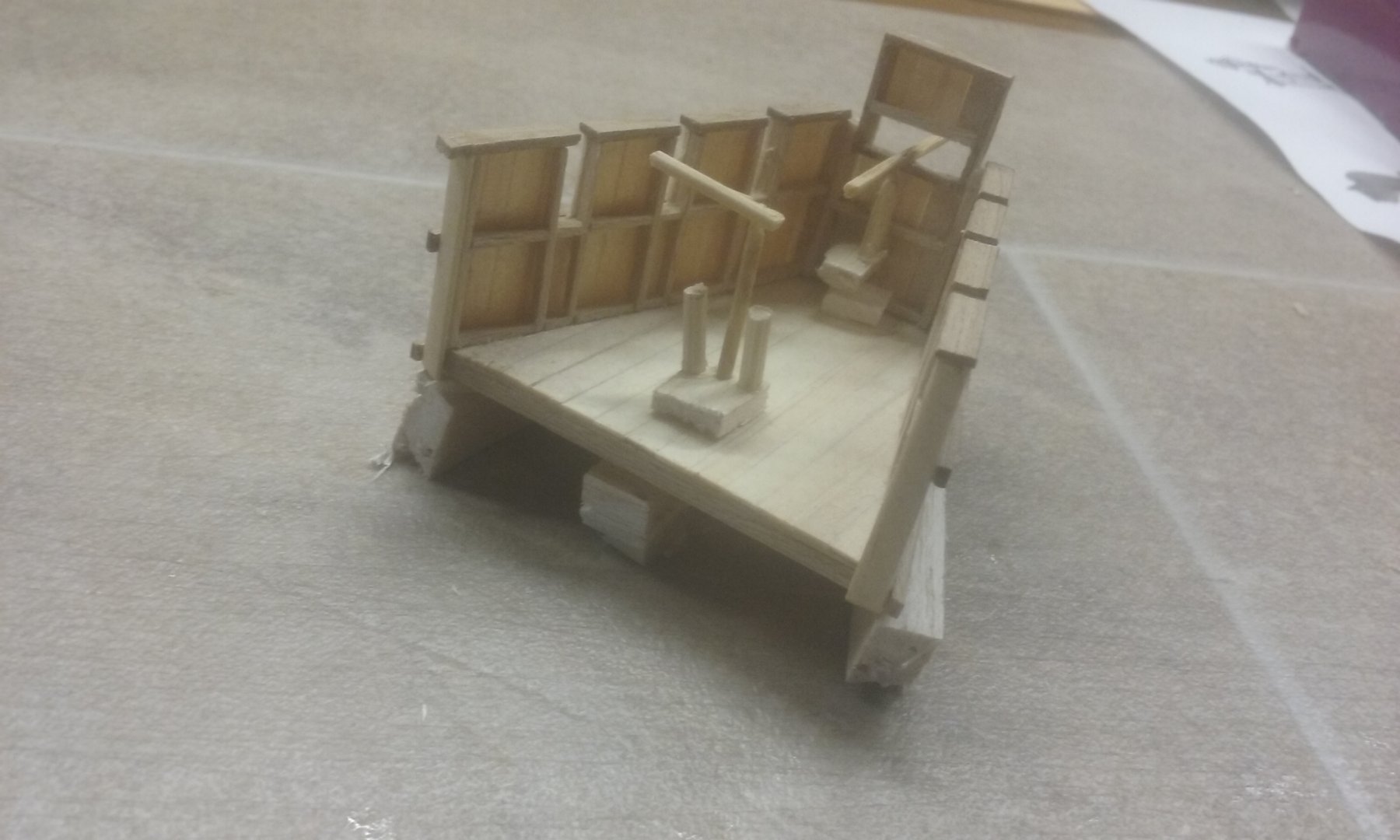
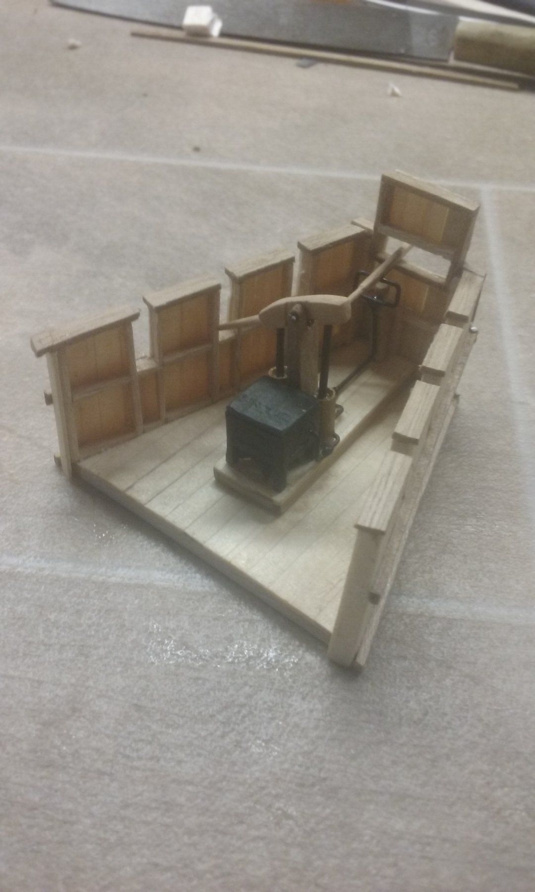
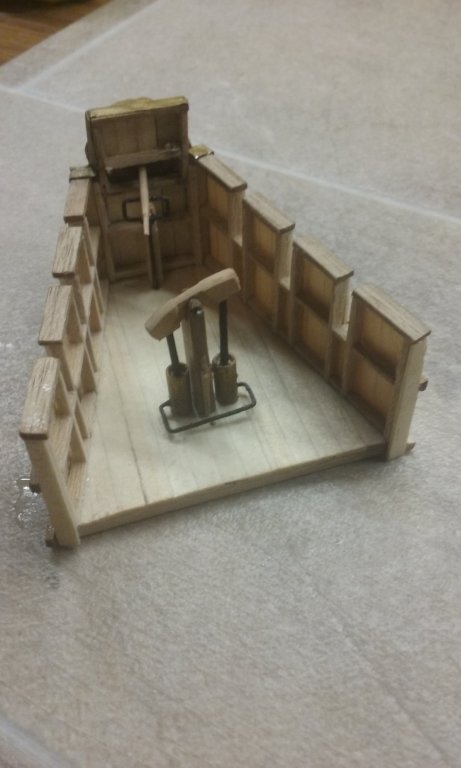
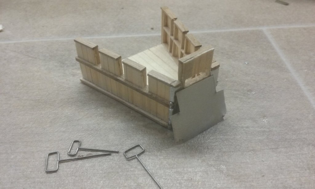
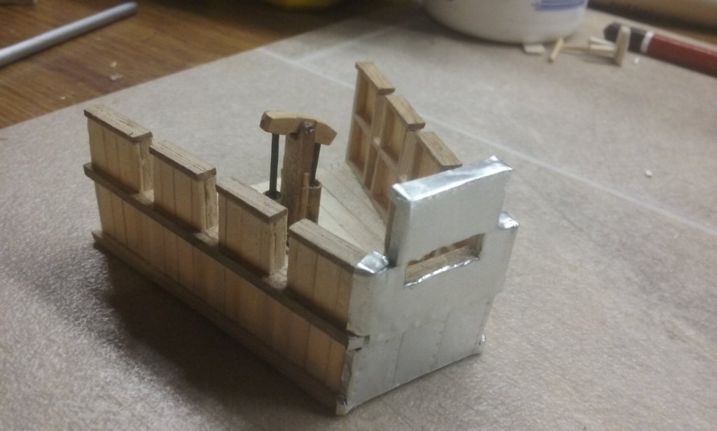
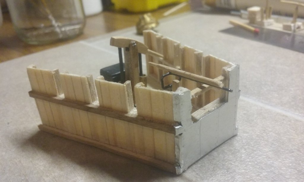
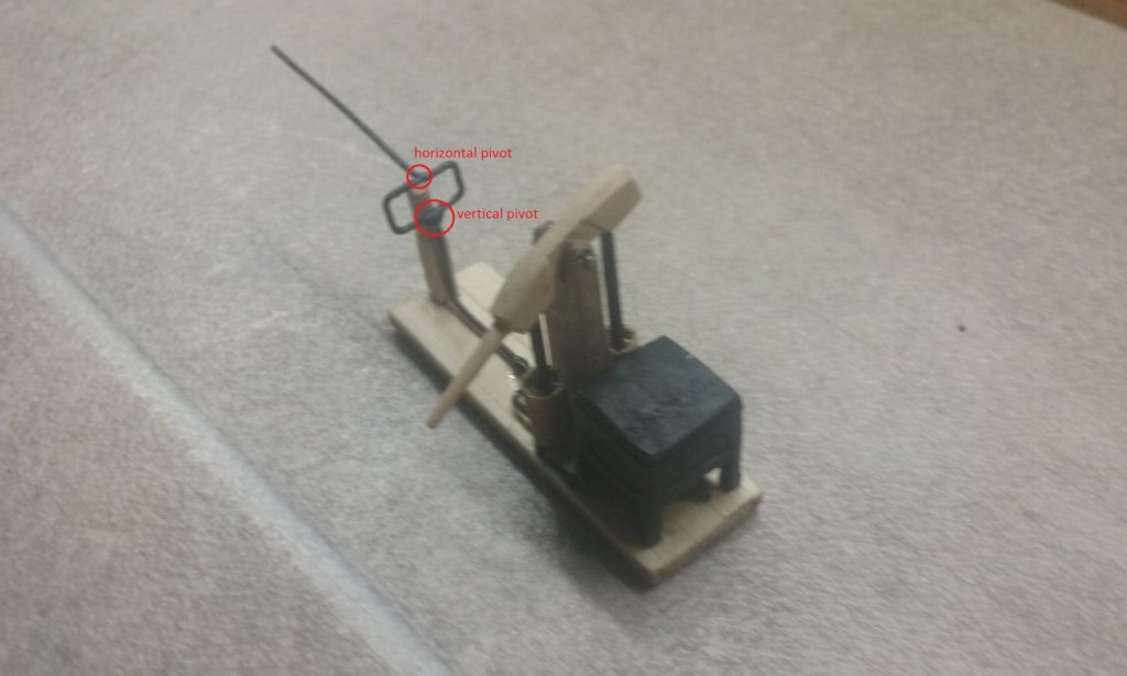
In the process of making the siphon a permanent feature of the ship, rather than a self-contained unit. First I've put fake bronze cladding on the raised portion of the forecastle's fore parapet. I used the thin aluminium sheet from a can of cat food and will paint it to resemble bronze. Note also three attempts to duplicate the "rectangle" of pipes I made for the first version of the siphon. Isn't always the way, I got it right really easily the first time but had no end of trouble trying to do it again. In the end I pulled the original siphon apparatus to bits and re-used the bits I'd made the first time. Sticking the cladding on with epoxy. Not totally happy with it - it's still a bit rough and ready compared with how I wanted it. I guess to really get on top of it I just need to do lots more practice working with sheet metal at a small scale. And in the meantime be satisfied with what I've done at the current level of skill. Inserting the pillar to support the "pipe" riser, and cut holes in the deck for the pump assembly. The pump in place - compare it with the photos in my previous post. In these photos the sheet cladding isn't fully glued down yet. I think this works better. Considerably more deck room. Note in the final photo the pump handle up against the upright containing the pivot. There's one in the previous photo on the other side of the unit, but it doesn't show up well. The handles are glued in place but I think I'll have to make some sort of clamps or fittings for them. Steven

-
Beautiful work, Dick. The hull has really taken shape well. Regarding the side rudder, I take it you already have the TAMU paper on the development of rudders/steering oars? Steven
- 263 replies
-
- 2
-
-
- nave tonda
- round ship
- (and 2 more)
-
That's amazing Yancovitch! I've got 50 oarsmen to make for my dromon and I was intending to cast them, but with almost no experience at all I was not looking forward to it. This site is a tremendous resource! Many thanks. Steven
- 73 replies
-
- 3
-
-
- mediterranean
- galley
- (and 1 more)
-
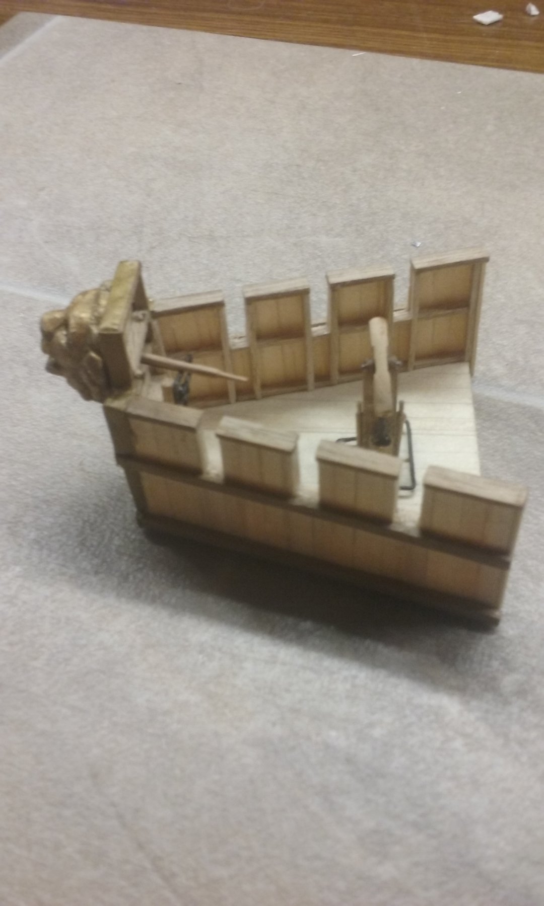
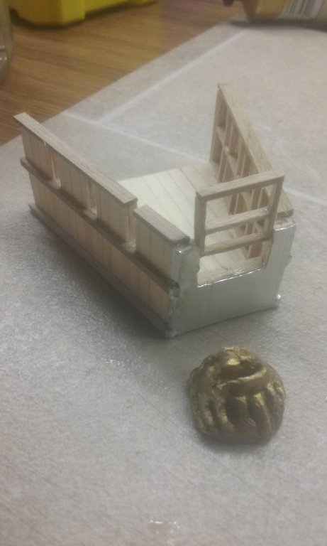
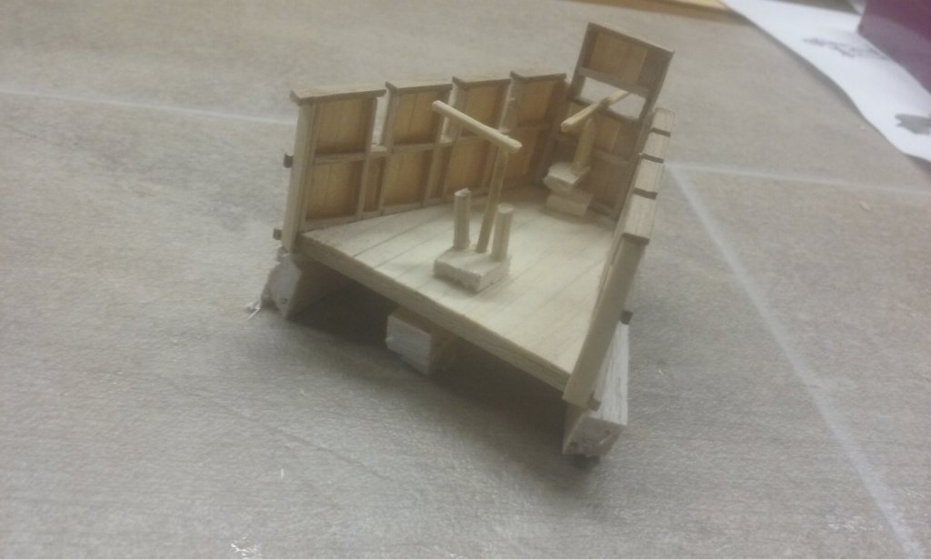
I've raised the level of the gap for the siphon in the forecastle parapet and added an extension to fix the lion's head to as well as acting as a shield against the heat of the flame. I've also been having second thoughts about the siphon. My original plan was to have the oil reservoir at the break of the forecastle, below the deck, with pipes coming up through the deck to the pump. Then presumably the pipe/s would go under the deck and up to the siphon. I hadn't really thought about it past that, then I saw the videos and made an apparatus that followed their design. But now I'm thinking of revisiting the original idea. It would make for a much less cluttered layout - the forecastle turns out to be rather short of space - and if I don't try to fit everything together as a single apparatus the pipes could be longer so the pump could be further back on the forecastle where it's wider to allow for more room for the rest of the marines using the forecastle in battle (if that's what they did when the siphon was in use!). Here's the current layout And here's what I have in mind: Additionally, it's occurred to me that the pump could have two handles if they were removable, as on a capstan. That would mean the pump could be a permanent fixture on the forecastle and hardly get in the way at all, and having two handles would allow for more efficient pumping. I haven't fully decided whether I'd make a new apparatus from scratch or re-use the pieces I've already made. Steven
-
A few points to note: The videos make it very clear that this was a fairly short-range weapon and that it would only work if there was either no wind or a following wind - otherwise the flames would be blown back onto the ship itself. I forgot to mention that I painted the pipes black to simulate pitch, as sealing the joints seems to have been a major issue and the Haldon people used the traditional medium to seal them. Windler seems to have overcome the problem by covering everything with some sort of extruded stuff - it's hard to see from the video what it is, and the issue is not mentioned in the voiceover. Steven
-
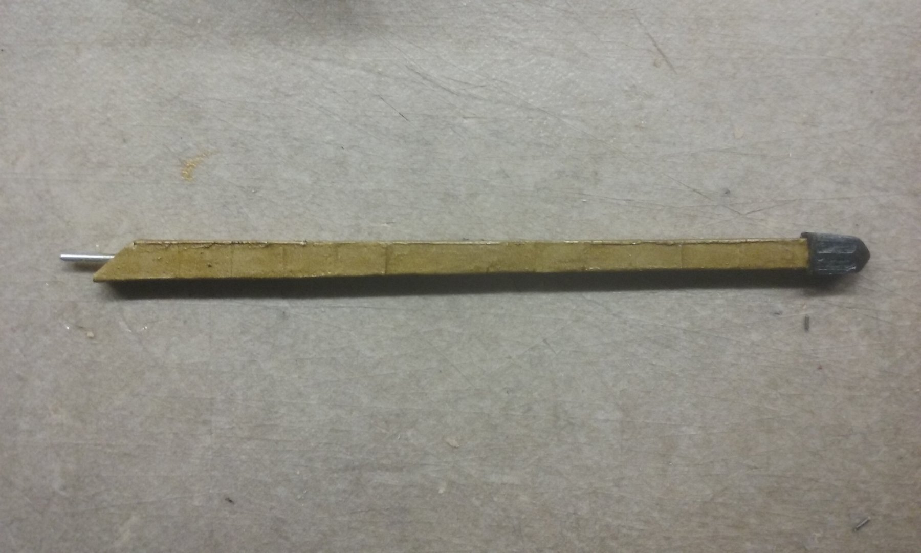
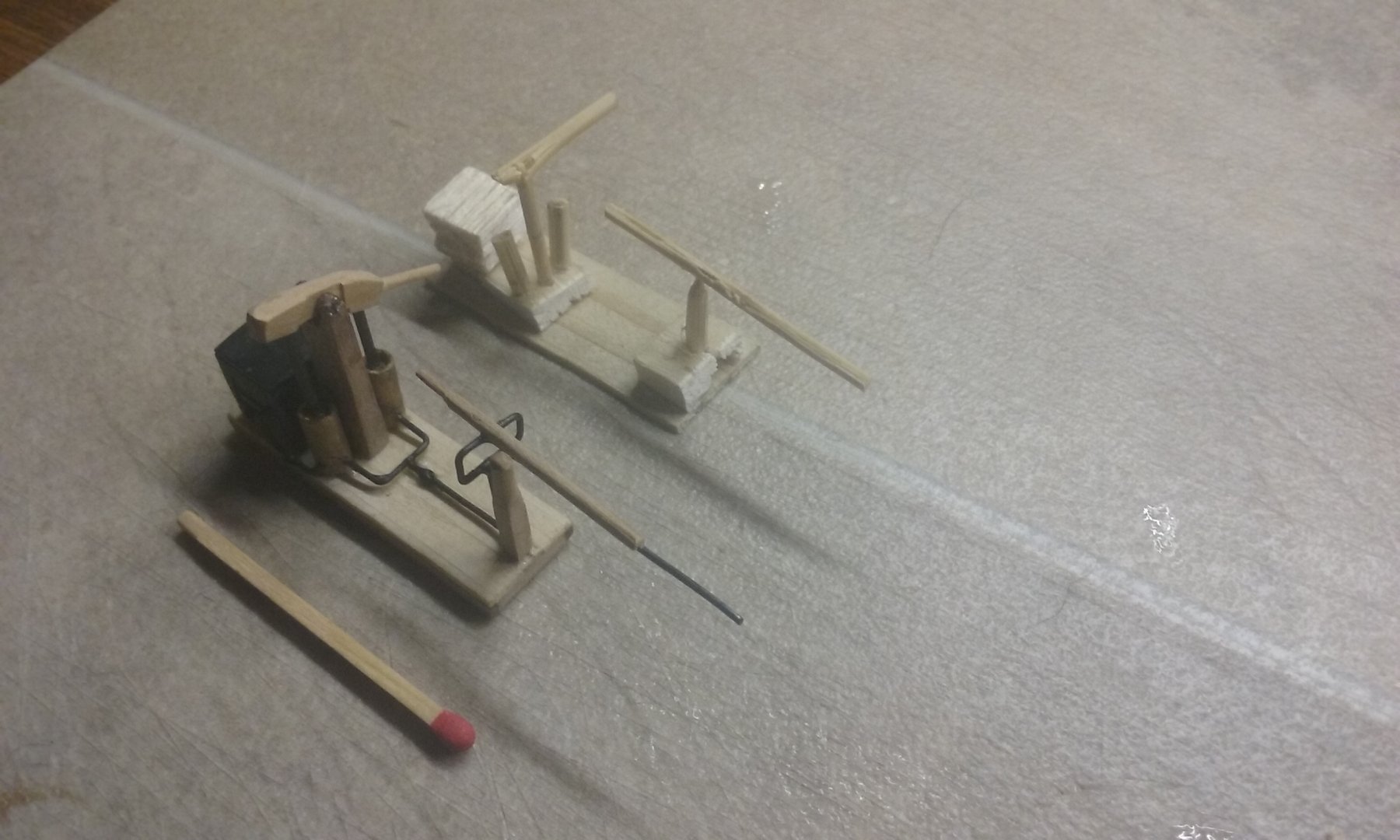
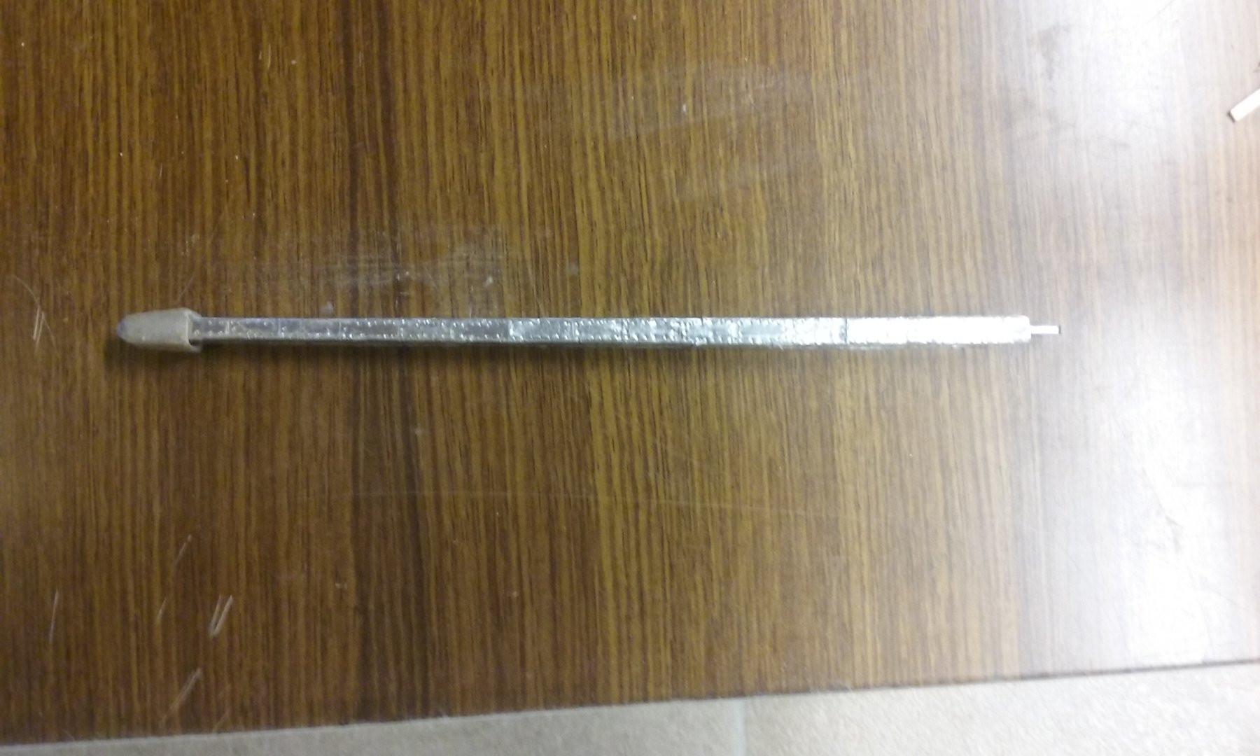
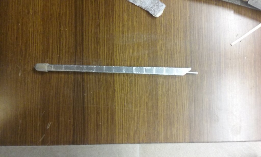
Oh, don't be fooled. That's my 1 metre long match. I got it from IgorSky 😀. Thanks everybody for all the likes. Unfortunately I've now found I have to do some adjustment. The nozzle was too long, so I've cut it back a bit, and it's also going to be higher than I thought so I'll have to adjust the forecastle so the parapet and the lion's head are higher . A bit of a nuisance, but I think it's inevitable with so many variables that can't be related to each other until it's time to put it all together. Steven
-
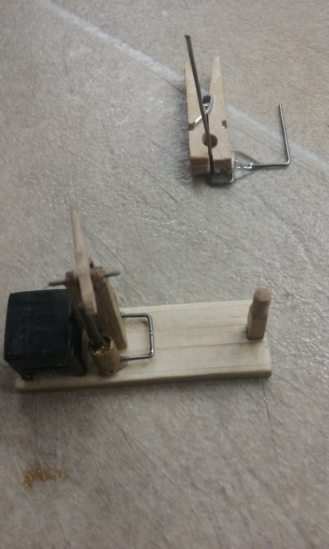
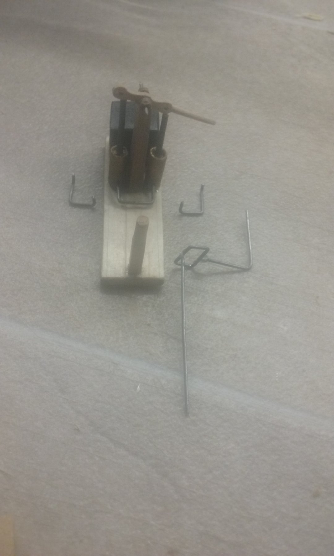
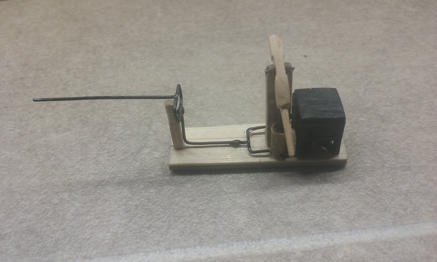
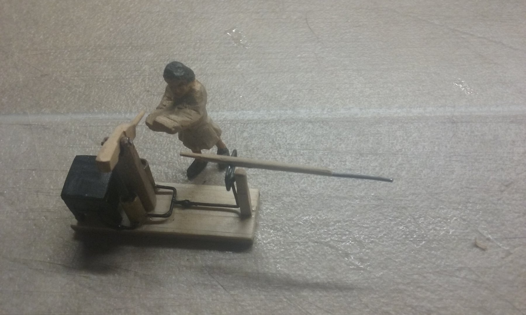
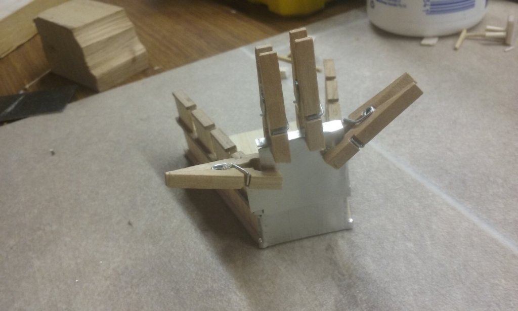
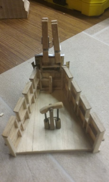
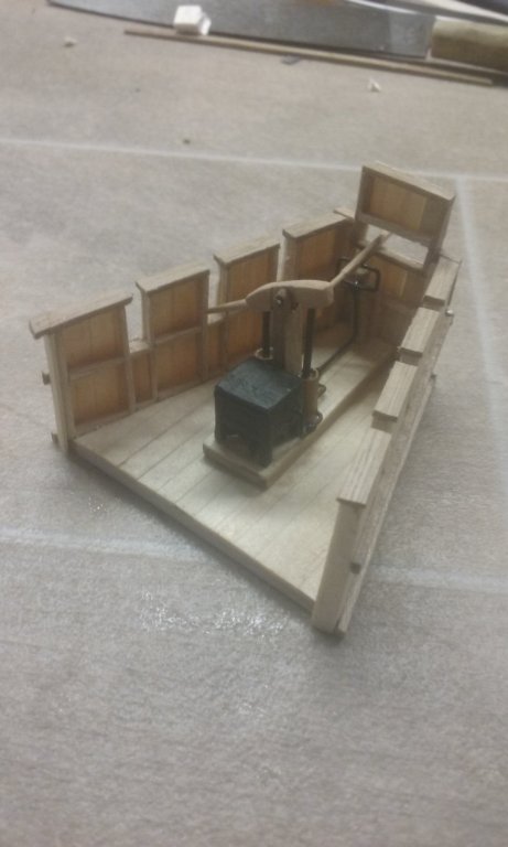
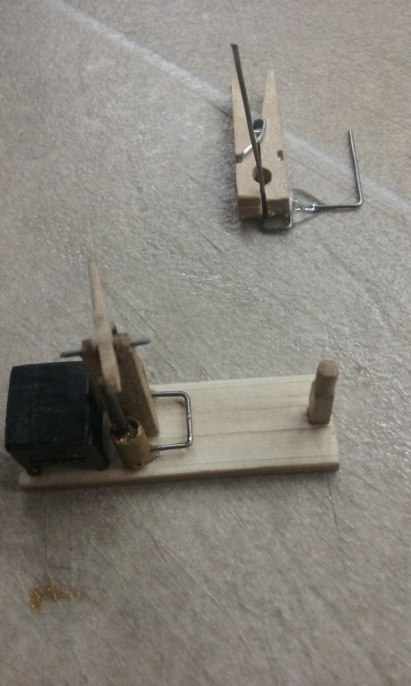
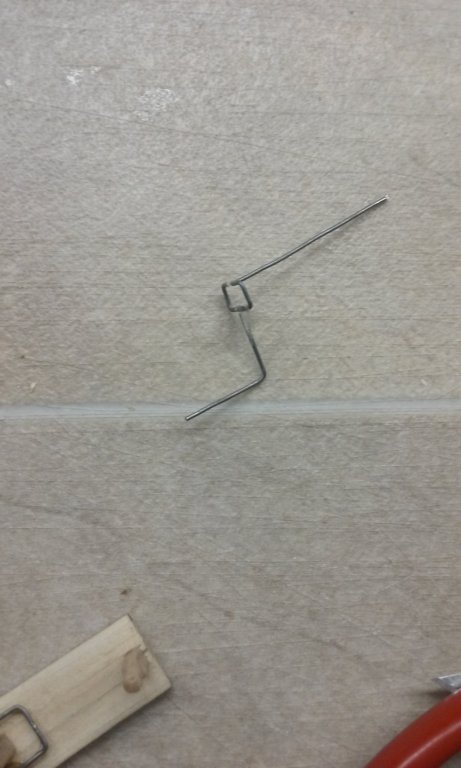
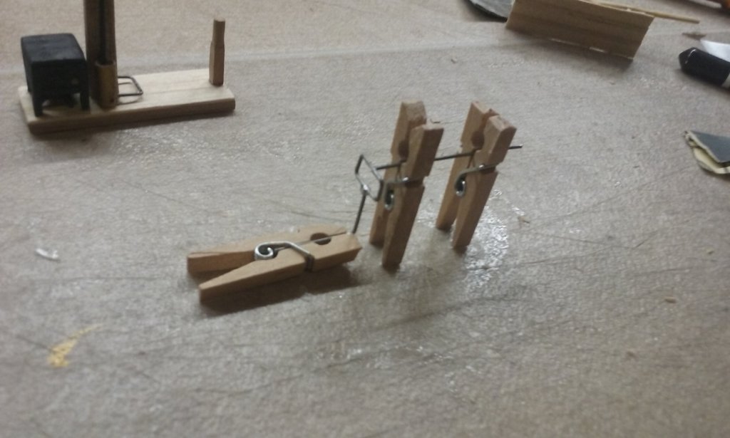
The siphon is complete. I've been concentrating on the pipes to deliver the oil from the reservoir to the pump and thence to the nozzle. Made from thin wire, I first made the "pipes" forward from the two cylinders. In the background, my first (failed) attempt to join the riser pipe to the nozzle assembly. Second (successful) attempt to attach the riser to the nozzle assembly. I made a jig from three miniature clothes pegs and added a dab of epoxy glue between the pipe "rectangle" and the riser. And here's the completed assembly Then the pipes between the reservoir and the cylinders. Wasn't happy with the pump lever, so I decided to make another, with openings on the bottom for the connecting rods. Three attempts later I finally got it right. Roughing out Lever in place, and riser/nozzle assembly attached to the pump. Note the "blobs" on the pipes between the reservoir and the pump, and between the pump and the riser. These are to represent one-way valves in the pipes, to stop the oil flowing backwards once it's pumped forward. And the handle to control the nozzle. As you can see, the whole assembly should be able to be handled by one man, as demonstrated in the Richard Windley video. And here is the completed assembly compared to the roughed-out model I did before starting. Pretty happy with this, though looking at the photos I see the nozzle is a little out of line at the front. I suppose I should fix it. Steven


-
Hello.... I am new here to the forum
Louie da fly replied to mfrazier's topic in New member Introductions
Welcome to MSW, Mark. I second vossiewulf's advice. A relatively simple model to start with is a good idea - though you have made ship models before, so maybe you already have the experience and skills needed. I look forward to seeing your build log when you get stated. Steven -
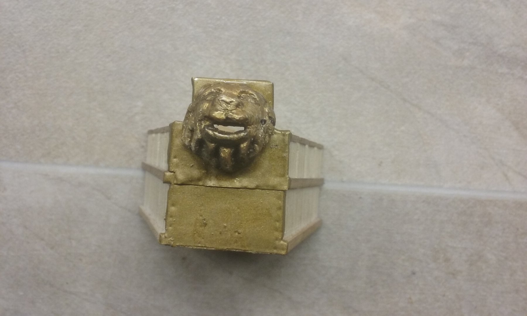
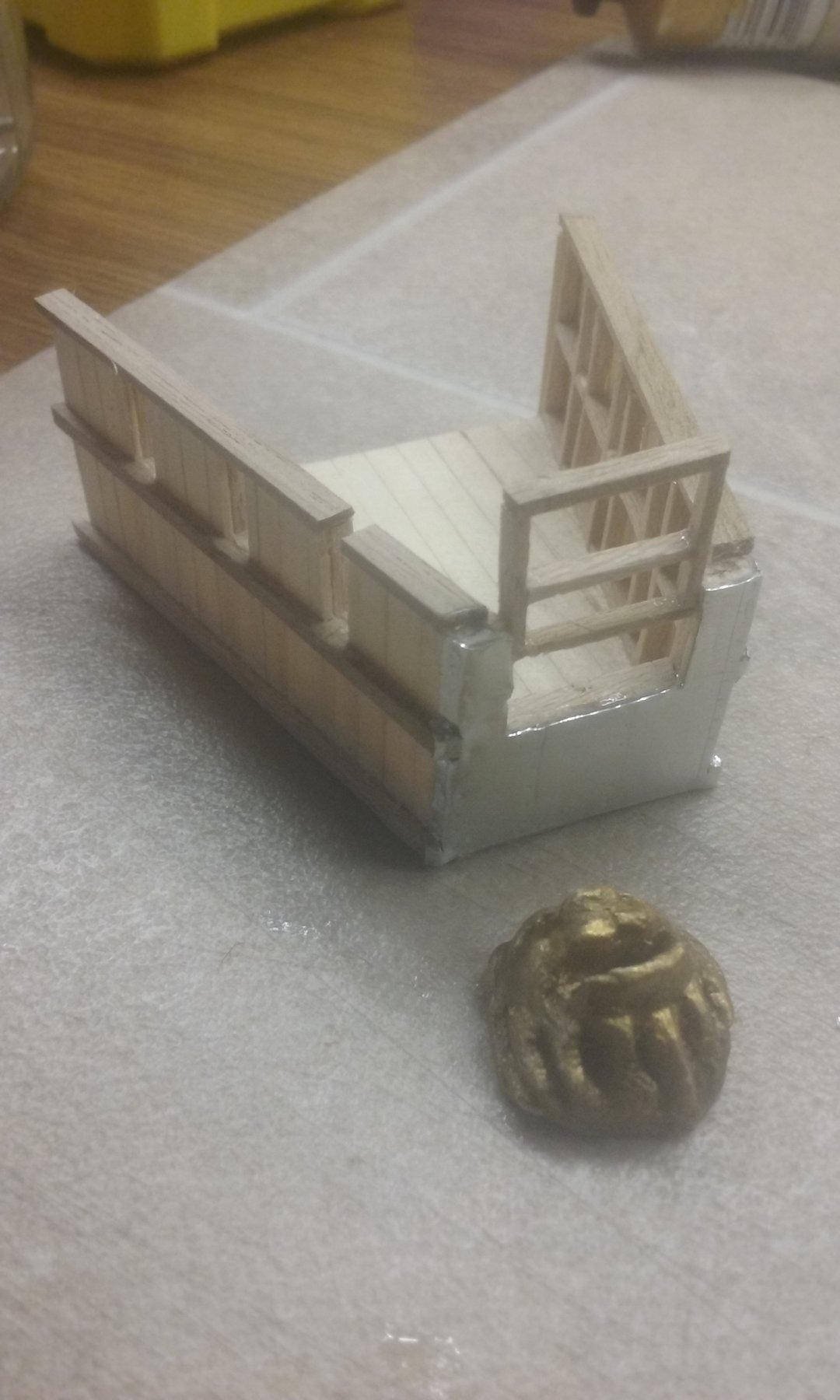
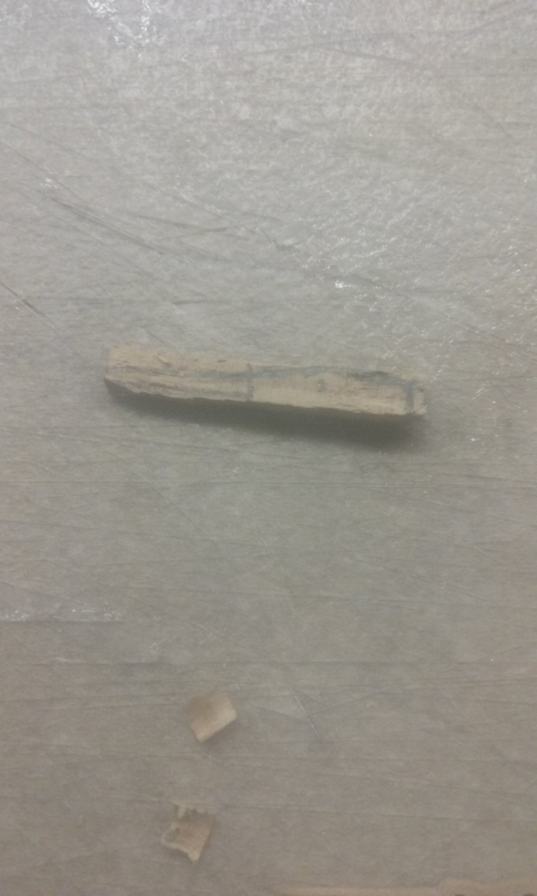
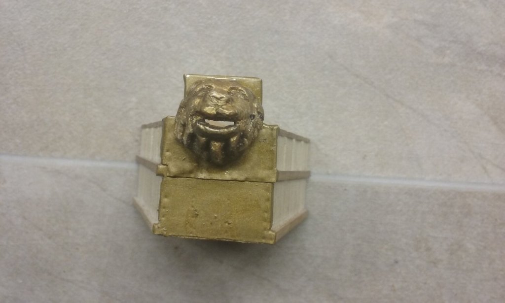
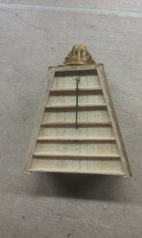
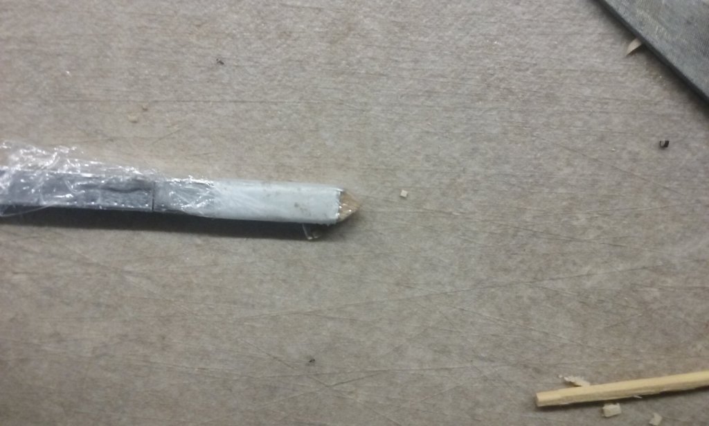
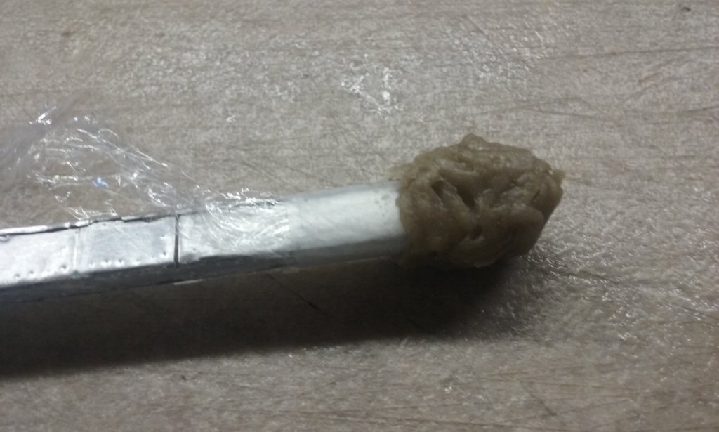
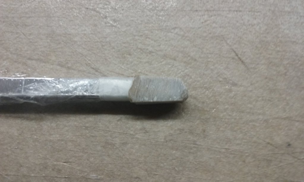
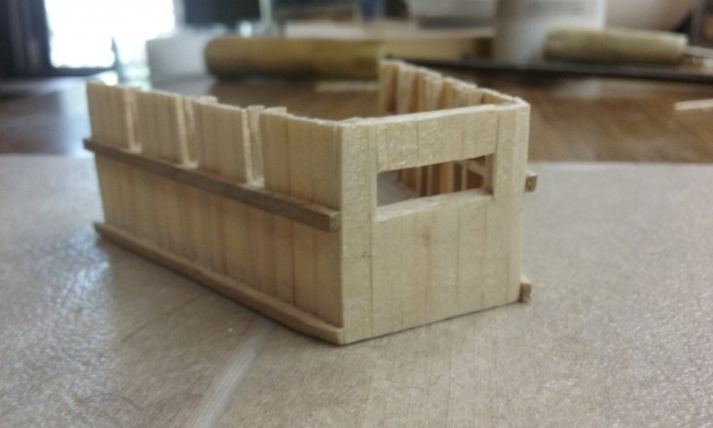
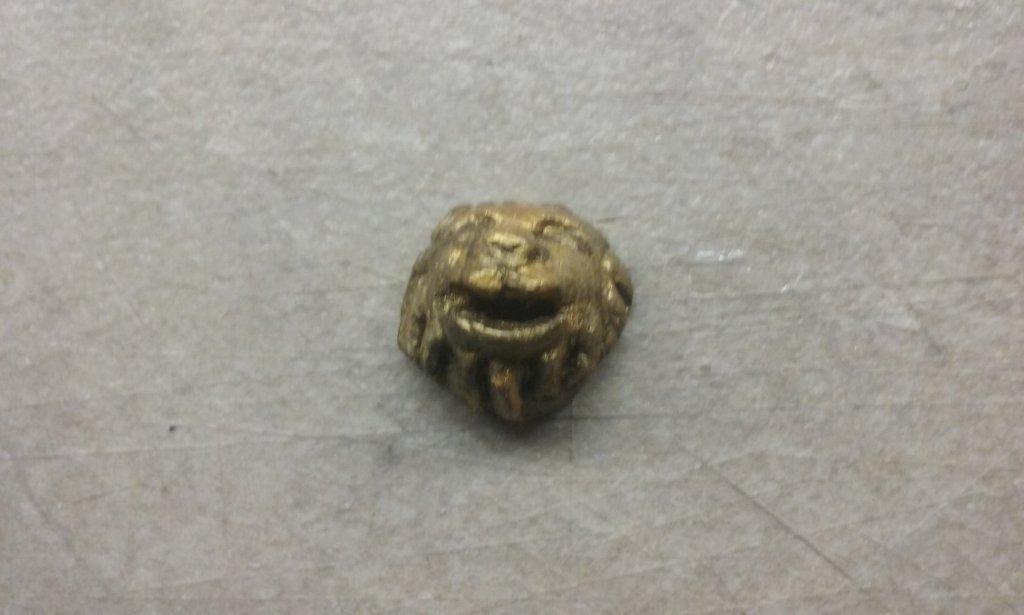
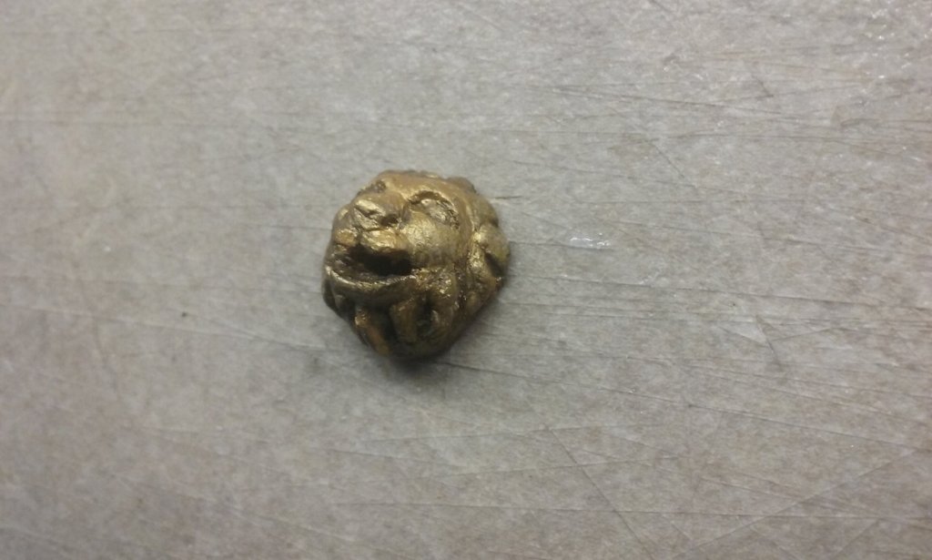
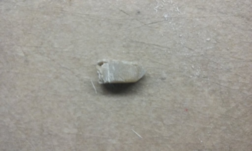
Working on the forecastle, the siphon assembly and the "business end" (iron head) for the spur. The forecastle with a slot in the front of the parapet for the nozzle of the siphon. The idea is that the nozzle should be able to rotate from side to side, and to a certain extent up and down as well. Here is the pear wood lion's head which is the housing for the siphon nozzle, painted to look like weathered bronze. I've hollowed out the back so the nozzle can stick through his mouth. The head for the spur - I'm no good with sheet metal, and neither wood nor cardboard did the trick so after a lot of pondering I decided to make it out of what we in Oz call "car bog" - bodywork filler. I wrapped the spur in cling wrap, held in place with sticky tape, so the bog wouldn't stick to the spur before I was ready. Bogged The bog filed roughly to shape and taken off the spur. The cling wrap worked a treat. Filed down to its final outside dimensions and stuck on to the spur with Araldite (don't know the generic term, but I believe it's a two-part epoxy) There's still some tidy-up work to be done on both the forecastle parapet and the head of the spur, but it's coming along well. Steven

-
HMCSS Victoria 1855 by BANYAN - 1:72
Louie da fly replied to BANYAN's topic in - Build logs for subjects built 1851 - 1900
As usual, beautiful work, Pat, and wonderfully fine detail. The worm drive in particular is very impressive. As "The Sentimental Bloke" said, "I dips me lid". Steven- 993 replies
-
- 7
-
-
- gun dispatch vessel
- victoria
- (and 2 more)