DONATION DRIVE - SUPPORT MSW - DO YOUR PART TO KEEP THIS GREAT FORUM GOING!
×


Louie da fly
-
Posts
7,989 -
Joined
-
Last visited
Content Type
Profiles
Forums
Gallery
Events
Everything posted by Louie da fly
-
 Again, too little available information, Carl. I can't think of any ship of that period and type in the archaeological record where the deck is preserved with the opening for the companionway intact. But as I mentioned, I think any sailing ship, even from the 18th century, is likely to have had pretty much the same arrangement and would work as a model for mine. Perhaps a chebec would be appropriate? Or perhaps a renaissance galley - but there's only one genuine one in existence as far as I'm aware, the Sultan's kadirga in Istanbul. Steven
 -
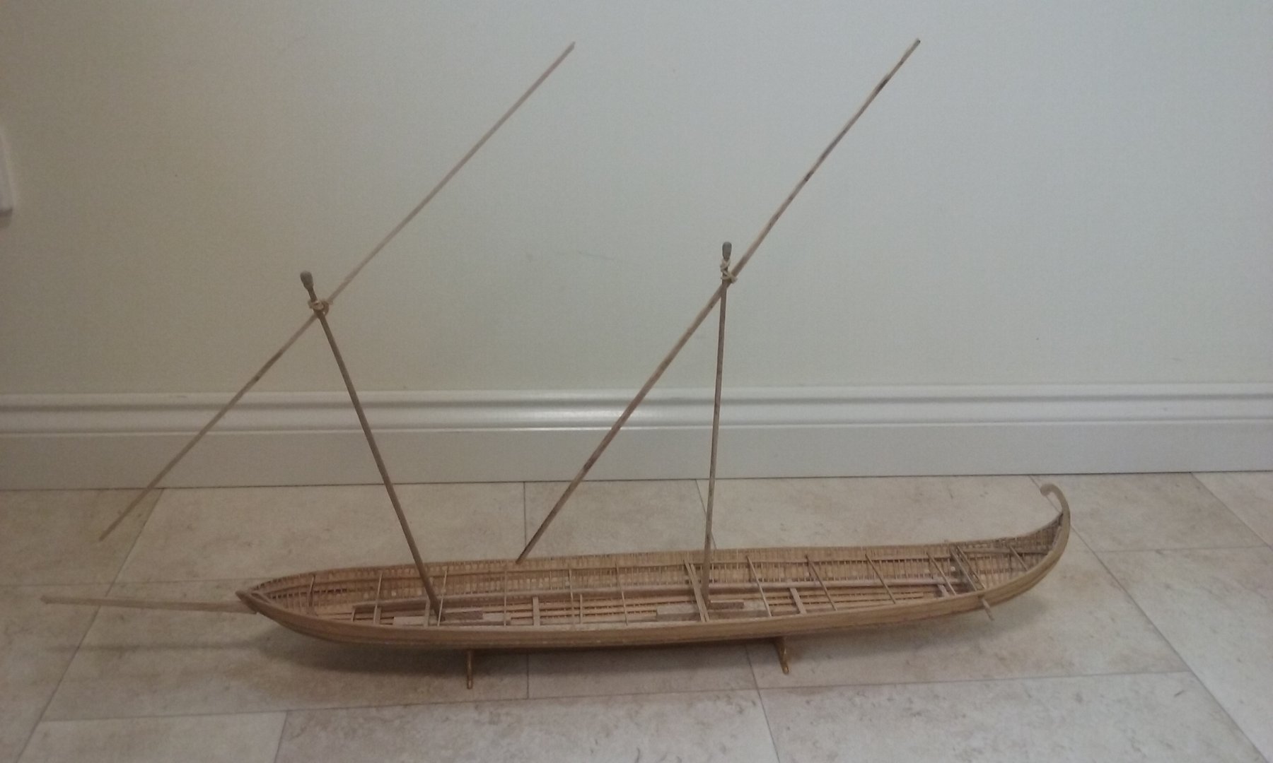
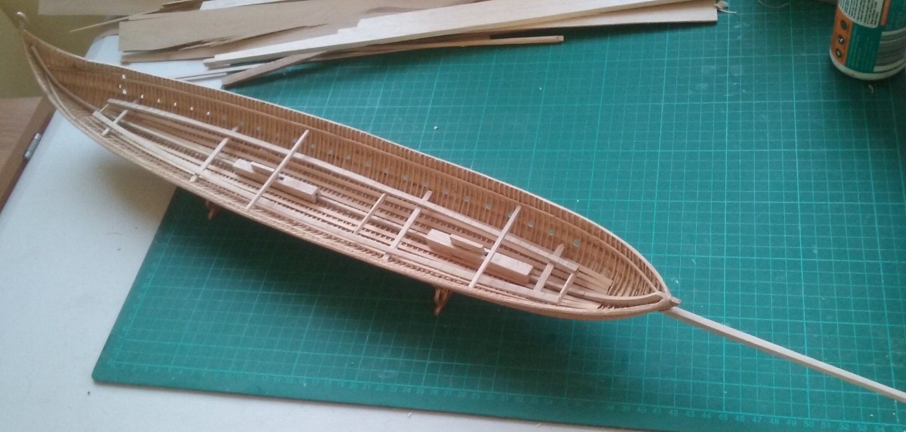
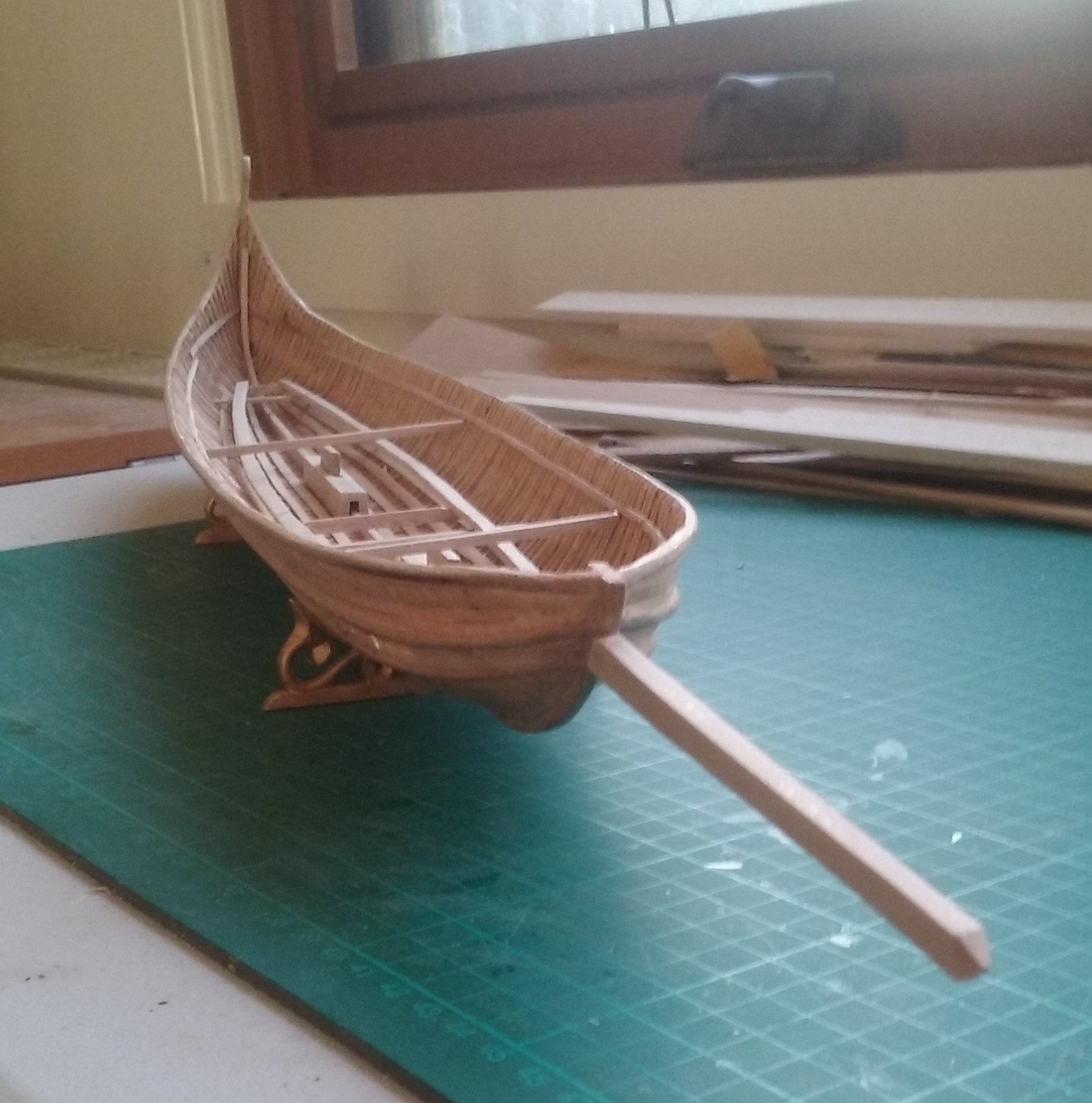
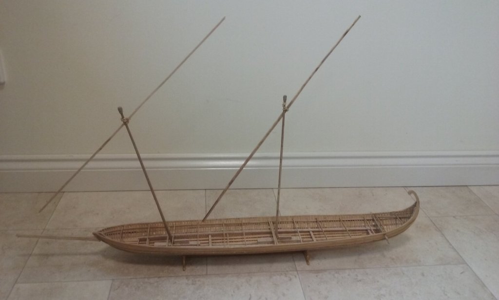
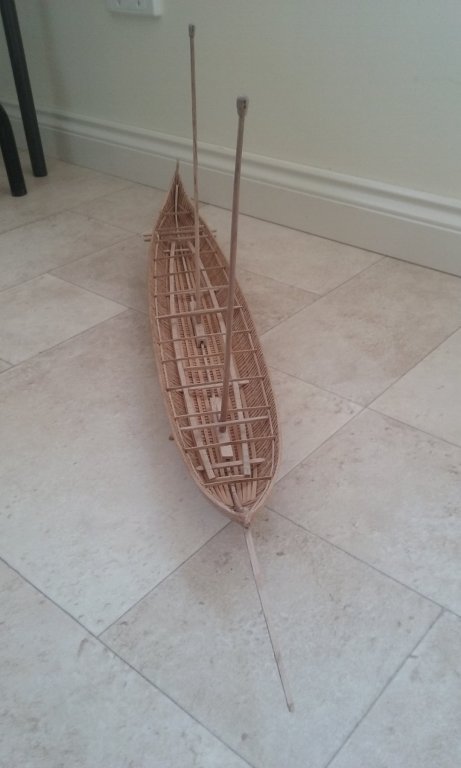
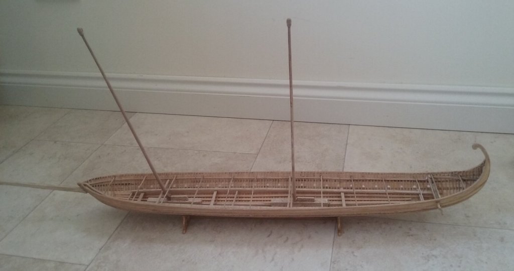
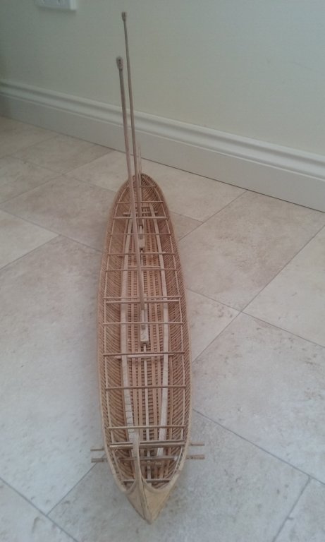
Doing a test fitting - mainly to work out how long the yards are in relation to the hull to see where to put the supports for the yards when they aren't in use, but also to get an idea of how she'll look when they're rigged.These are just bits of wood - I've yet to make the yards themselves. It's a little known fact that the yards of Byzantine ships were fixed to the masts with large rubber bands 😁. On a more serious note, I will shortly need to locate the companionway which leads below decks, and I really have no idea how big to make it. Can anyone advise me of the usual size of the opening in the deck for a companionway, and the size and angle of the ladder leading belowdecks? I realise there are no available comparisons of similar ships, but I should think the size of opening and angle of the ladder wouldn't change that much over the centuries. Steven
-
A liburnian! Wonderful! Nice to see someone making one of these. I find ancient and mediaeval (oh, and renaissance!) ships more interesting than any others. Watching this with great interest. Steven
- 23 replies
-
- 2
-

-
- liburnian novilara
- marisstella
- (and 1 more)
-
Looking really good, Chris. We do get some good weather here in Ballarat. Sometimes as much as 10 minutes at a time😀! Steven
-
Beautiful job, Greg. I have to say I prefer the grainy photo (though I agree B&W would be better than sepia) - it looks like a photo taken at the time. Modern photos are just too crisp and clean to get the historical "feel" across as well. A real achievement. Steven
- 405 replies
-
- 8
-
-
- tamiya
- king george v
- (and 2 more)
-
A brilliant build of a gallant vessel. My hat's off to you, Carl. Steven
- 292 replies
-
- 8
-
-
- g class destroyer
- trumpeter
- (and 4 more)
-
Mark and Carl, thanks for the kind comments. The space allowance was based on crewmen about 1.67 metres tall (= 5'6" in the old money). This may or may not be a little taller than they were in the day, but I think it should be close enough and allows for someone a little taller than the average of the time. On the other hand the Varangian bodyguard is 1.80 metres (about 5'11") tall - as the Arab traveller and chronicler Ibn Fadlan wrote: "Tall as date palms". For Vikings and Anglo-Saxons of the same period the average height was 1.72 metres (5'8") though according to archaeology it's "not uncommon" for them to have been over 6 feet tall. I allowed for the top of the lower oarbenches to be 450mm (18") above the top of the keel, and the head of the"standard" oarsman to be about 830mm (2'9") above the seat. This then allows for 32mm (1.25 inches) headroom when the oarsman is sitting bolt upright. Not very much, but hopefully enough. Steven
-
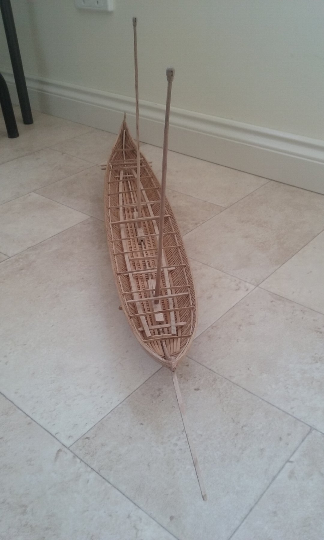
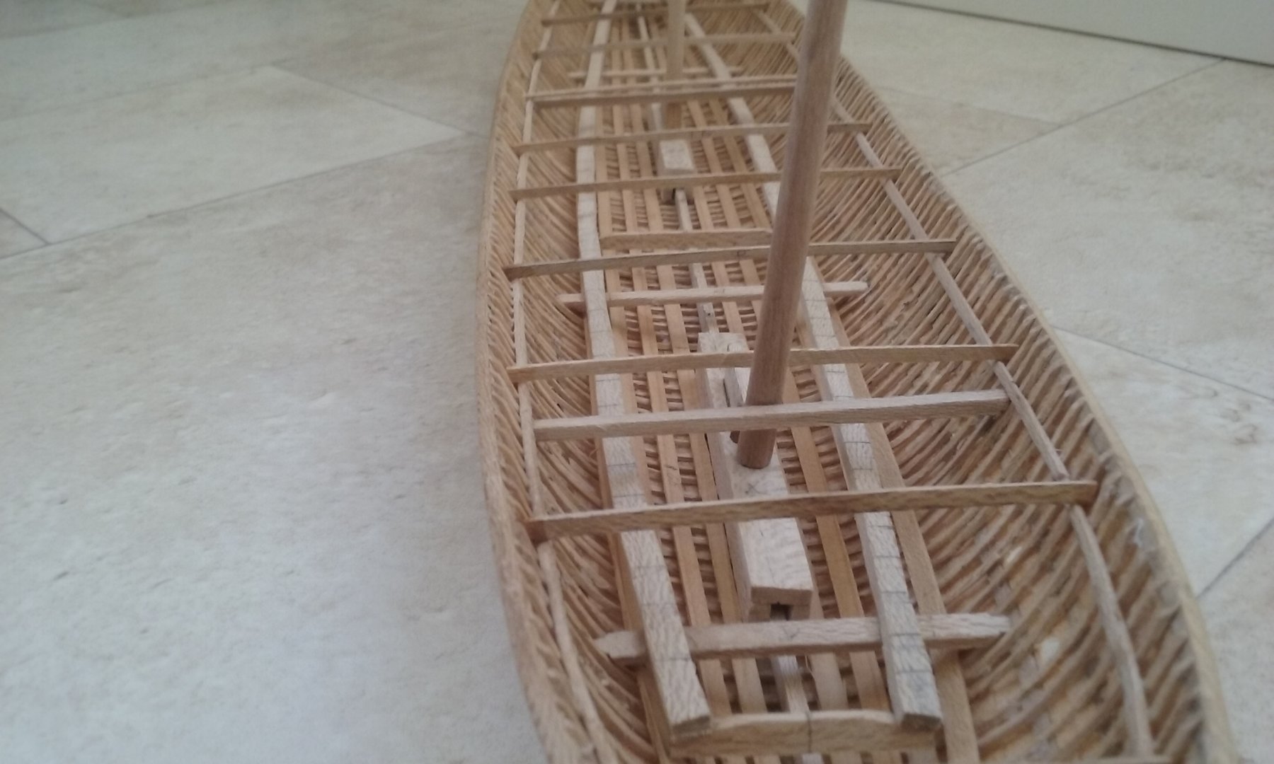
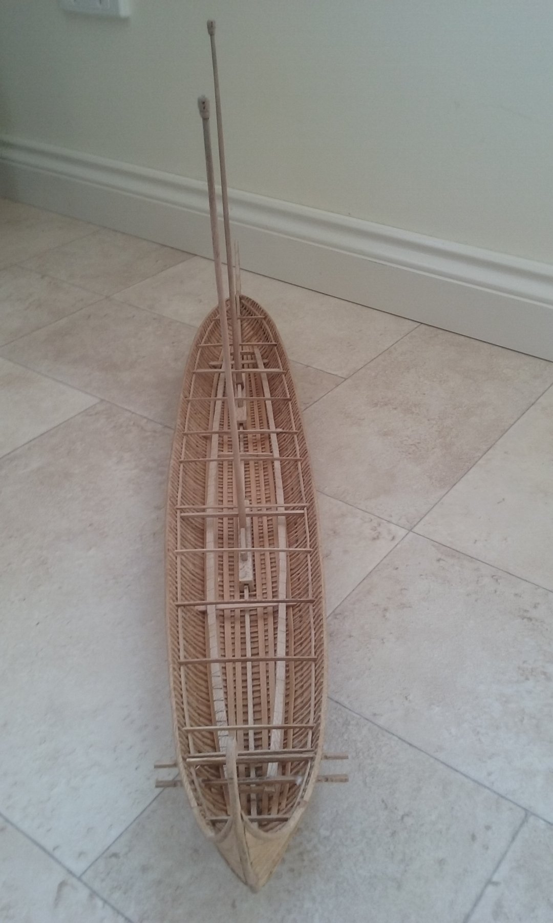
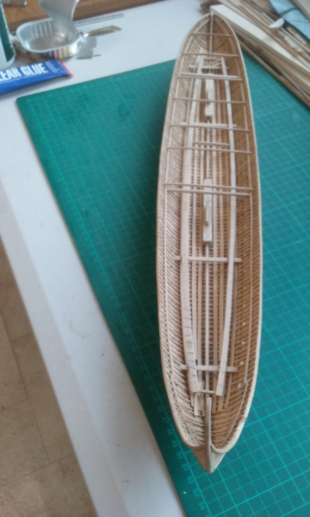
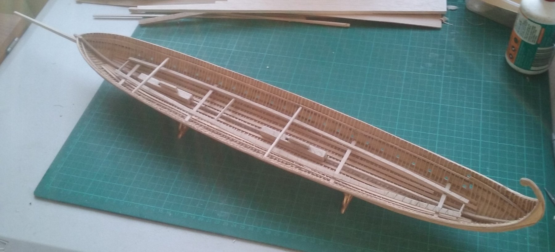
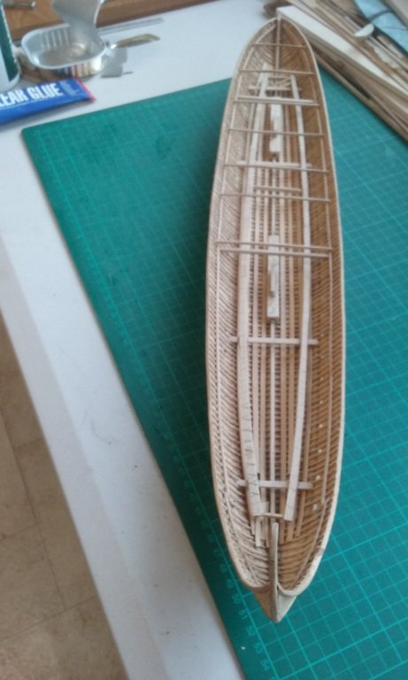
Here's the dromon with masts and spur dry-fitted and deck-beams glued in to form the line of the deck, at intervals of about 4-5 beams apart. When they're all in place, there will be a deck beam for every two frames - so there'll be something like 52 of them, and in full scale they'll be 0.48 metre (approx 18") apart, or (where the oars are) two per oarbench. This ties in with the known intervals of 13th century Sicilian galley deck beams. In the close-up picture you can see the very slight upward curve of the deck beams. As I mentioned above they'll be approx 100mm deep in full scale. I'd have liked to make them deeper, but there are serious issues with headroom for the lower oarsmen vs the overall height of the vessel above the waterline and even more importantly the height of the upper bank of oarports above water level. The higher the oarports the steeper the angle of the oars and the harder it is for the upper oarsmen to row. As it is, the lower oarsmen will have just enough room not to bump their heads as they row. Though for this depth of deck-beam there should be fore-and-aft support beams held up by columns at intervals, I won't be putting them in - just too much complication for something that will never be seen. I've also put in the cross-beams for the rudder structure now, to keep from possible interference later on when it's too late to fix. She's starting to look like a real ship! Steven

-
That's what I thought, and that's what I've done. But I think I started out a bit wrongheadedly, and I've since rationalised my way of doing things to produce the same result more simply and with less effort. Steven
-
A nice project, and I especially like your creative use of Lego. It could be a worthwhile tool for other modelling activities. Steven
-
Thanks for the likes. Druxey, there's no Byzantine ships been found with deck beams intact, so nobody knows for sure. I'm just going by Zu Mondfeld, as I have no other information to work off. So, I'm right in thinking the deck beams are all arcs of the same big circle, not that the vertical distance from the gunwale to midships is the same for all of them (which would mean a very pronounced curve where the deck is narrow)? Steven
-
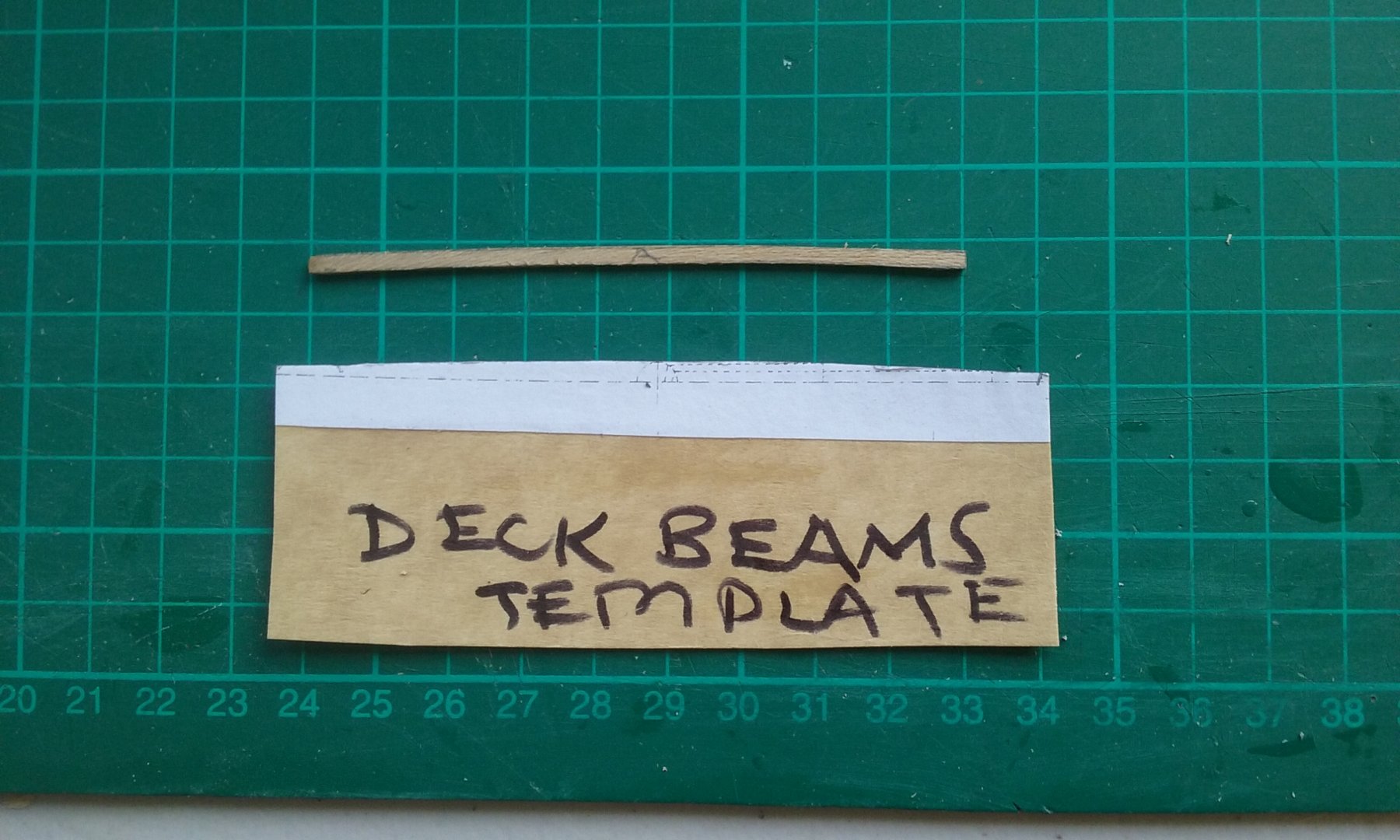
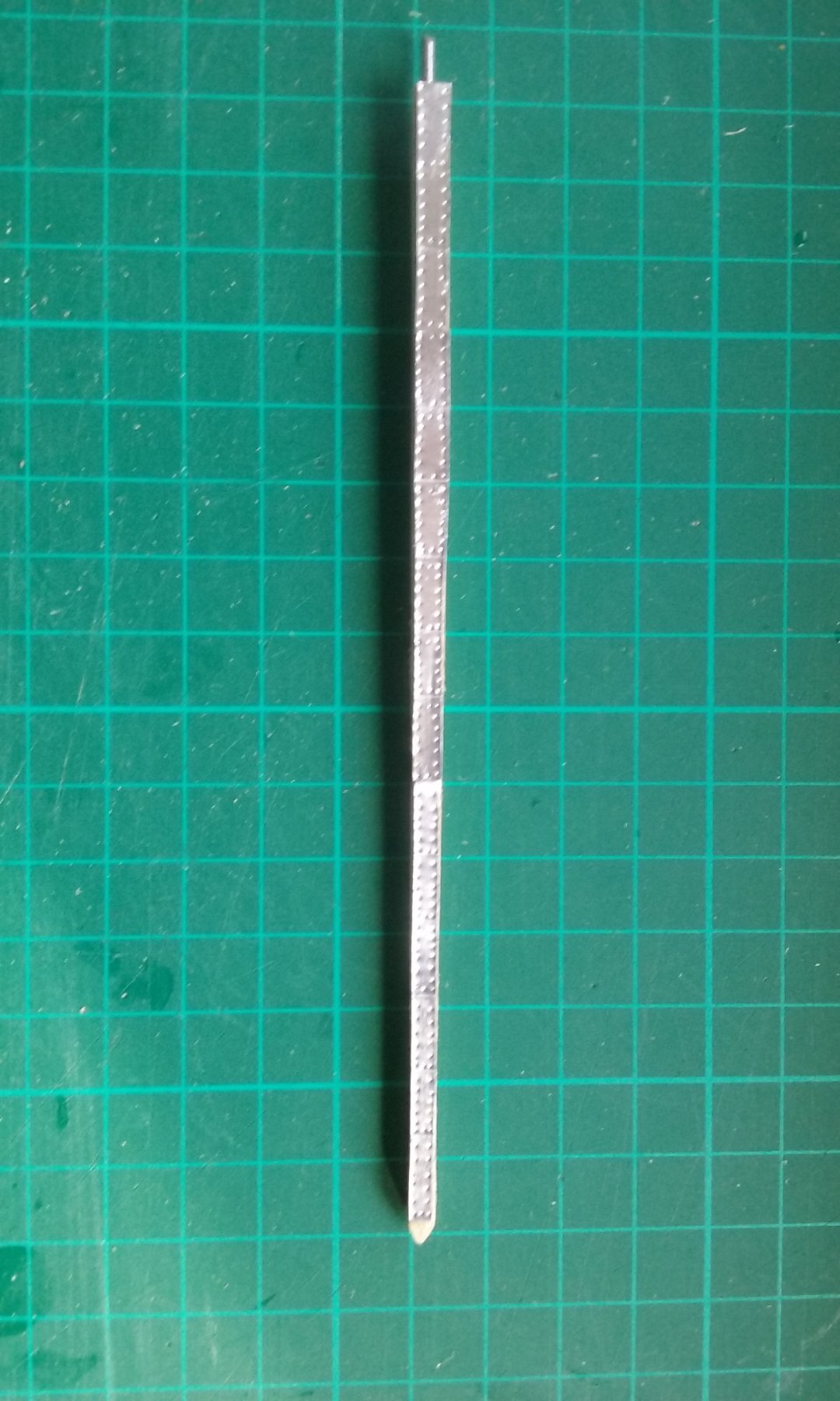
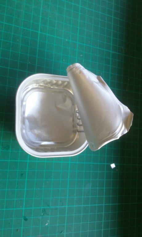
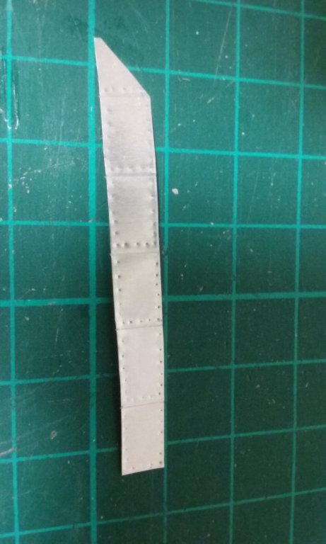
Started plating the spur. After some thought I believe they would have used bronze (or as the archaeologists say nowadays, copper alloy) as it's easier to work into thin plates with the technology available at the time than iron, and the thinner (and thus lighter) the plates the better - they don't have to be strong, just cut the effects of flame for a short time to protect the timber underneath. I used foil taken from our cast-off tins of cat food (the tin itself, not the lid, which unfortunately has an embossed pattern). It's thin enough to emboss easily but strong enough to maintain its shape. The cat doesn't seem to mind. Here are the plates for the bottom of the spur, with simulated nails to hold them in place. I noticed from another thread that coppering on a full-size ship's bottom is actually a little indented where the nails are, so I've done it this way on my spur. Each plate is about 1 metre (3 feet) long in scale, but I've made units containing several plates each, embossed to look like separate plates overlapping each other. I'll paint them to resemble weathered bronze when all the plating is done, and make an "iron" point for the business end - haven't yet decided how I'll do that. And for the starboard side. At this magnification they don't look as tidy as they do to the naked eye. Maybe if I'd taken more time I could have got them more precise, but from the archaeology on the Yenikapi finds it seems the Byzantine shipwrights weren't all that precise themselves. Two sides covered. Two more to go. The brass escutcheon pin which was to locate the spur into the hull was rather too short to be secure, so I've replaced it with a longer piece - the shank from a pop rivet. This is fiddly work and I need a break every now and then, so I've started on the deck beams. They are 1mm thick and 2mm deep (equivalent to 50mm (2") thick and 100mm (4") deep. I got the curve template from Wolfram Zu Mondfeld's excellent book Historic Ship Models. To get the deck to run smoothly, I've made beams at intervals about 4-5 beams apart and will then add the intermediate beams to follow the curve outlined by these major beams. Still in progress, and rather more complicated than I'd thought - I've discovered the hard way that the curve has to be measured either side from the centre of the beam, not from one end, and that the top of the beam has to be the same distance above the beam shelf at each end. And as each of the beams is a different length, that means each has to be made individually - no mass production shortcuts, dammit! Still, it's all a learning process, isn't it? Steven

-
This is looking very good, Dick. Precise workmanship, ingenious jigs and a fascinating and beautiful ship. I'm enjoying following this build. Steven
- 263 replies
-
- 1
-
-
- nave tonda
- round ship
- (and 2 more)
-
Yes, it might be - you mean at the lower end of the "chain"? And there's something a bit hook-like at the lower end of the gammoning, as well. Also, notice the guy in the bows of that galley is holding something like a halberd - it's almost certainly a "sickle" designed to cut the rigging of the opposing ship, something which was apparently common practice in maritime combat at the time. By the way, that picture is dated in the source I was using as late 13th century. Looking at the artistic style, if it is 14th, it's very early in the century. So, late 13th, early 14th, I'd say. Steven
-
Thanks for that, Dick. I had a copy of it (it's in my post of 3 August), but not in glorious colour like this one! I agree about the support on the right, but it's a bit hard to be sure exactly what the one on the left is made of. I'd interpreted it as a stylised representation of a heavy cable, taking the double twisted line as representing two strands, but perhaps they are supposed to be the links in a chain. If it is a chain, presumably the ones in the Vergil Aenid picture would be as well. Still trying to tie down details . . . Steven
-
Dick, I was in fact making my spur considerably shorter, then was brought up short (sorry!) by the following from Age of the Dromon (p203): "A contract for the sale of two spurs made of oak (robor), each 10.42 metres long and 0.25 metres wide survives from Genoa in 1267." To me, a written contract is much more reliable information than mediaeval pictures, which unfortunately often used a lot of artistic licence. Western galleys of the 13th century were about a third larger than Byzantine dromons and Prof Pryor has evidently used the relative proportions of the two kinds of vessel to reduce the spur in his dromon reconstruction from over 10 metres to only seven. I really feel I can't go any smaller than that, ithyphallic though it may seem (my spur's bigger than yours!). Looking at the pictures in my posts of August 3 and 4 above, I believe (in those pictures where it's shown at all) the support for the spur seems to be either a heavy cable (shown as two ropes twisted together) or, in other pictures, gammoning such as used on later bowsprits. Do you have any pictures showing a chain? Prof Pryor mentions it as a possibility, but I haven't seen any pictures which look enough like chains for me to think so. Pat, there's no mention of the spur being able to be removed at a moment's notice - or otherwise. Personally, I believe that once installed they would be permanent, if only because surprise attacks did occur - in fact if I recall correctly, the Byzantines lost at least one fleet that way. But there's so little information about such things; All I know of is the quote above and the following two passages. " . . . in the inventory for the Cretan expedition of 949, amongst the equipment to be supplied by the Department of the Vestiarion basilikon [Imperial Household] for 20 dromons, was specified: “20 peronia for the kataprosopa together with their katakorakes” . . . Peronion (pl. peronia) was a diminutive of, or a derivative synonym for, perone, which could mean a pin, or brooch, or buckle. It had many other senses in mechanical engineering, and was derived from peronao, “pierce” or “transfix”. Since only one of these peronia was to be supplied for each dromon, they must therefore have been major pieces of equipment and not pins, or bolts, or buckles. However, peronion in the sense of something that pierces has the right sense for a spur and speronus, one of the two medieval Latin words for the spur, was almost certainly derived from it. Surely peronia were the dromons’ spurs. The specification was that there should be 20 peronia, “for the kataprosopa, together with their katakorakes”. Prosopon had the sense of the front, facade, or face of anything, in particular of a ship, and one of the senses of korax was anything hooked for grappling or holding something. Reading the “kata” prefixes simply in their strengthening sense, we suggest that the real meaning of this specification was: “Twenty spurs for the faces [of the bows], together with their couplings”. Peronion was probably the Byzantine word for the spur and katakorax that for the coupling to the head of the stempost. (Age of The Dromon p207): Imagine 900 years from now trying to work out what a sheet, a tack and a brace were, based only on a list of equipment supplied to a fleet in the 18th century - that's how difficult the task is. Also from Age of The Dromon (p203) "In late antiquity and the Middle Ages spurs were not built as integral parts of the hull, as they were in the Renaissance. Contractsfor the construction of galleys for Charles I of Anjou, King of Sicily, specified neither the provision of spurs nor their dimensions, indicating that the contractors did not have to build them into the galleys." And that's all the information we have, and we should probably be grateful even to have that. There's so little data that we are forced to speculate and fill in the gaps with educated guesses. The reason I keep going on about Age of the Dromon is that it has collected in one place all the information available on dromons up to the 2006 date of publication, and I believe the reconstruction in the book is as close as we're likely to get, qualified only by the Yenikapi finds and possible future finds in the Black Sea. Steven
-
Not at all, Pat. I find the discussions on various aspects of these ships and how they operated very instructive and thought-provoking. There are so many questions we don't know the answers to, and questions and comments such as yours raise even more issues which may never have occurred otherwise, even to academics who specialise in such things. For example, one question I had right from the start was how did they organise toilet breaks? Can a single oarsman just leave his bench when he needs to? Keeping in mind that these were free men, not galley slaves chained to the benches. Turns out that not everybody rowed all the time - for example maybe only the forrard oarsmen rowed, or all those aft of the midships. But apart from that, it turns out (from practical experience in the trireme reconstruction Olympias) that oarsmen sweat so much that toilet breaks aren't needed as often as under normal activities. Who would have guessed that without the benefit of hindsight? And though I'd certainly been aware of the unwieldiness of the spur and the forces involved in ramming with it, until you raised it I'd not thought of the adjustment of the ship's trim necessary because of the weight of the spur forrard. Keep 'em coming! Steven
-
Roger, I agree with all of that, and in fact I started out making it shorter, then discovered documentation that returned me to the 7 metre length (see my posts of August 1). So it looks like I'm stuck with it . . . Pat, I don't know about a stone anchor. Certainly Byzantine ships of the 11th century had iron anchors (see the Serce Limani ship, for example), but they weren't all that heavy. From Prof Pryor's researches, it appears the anchors (called "irons" in the original Greek) were stored in the bow. I don't know if any anchors have been found among the Yenikapi wrecks. As far as I know, Byzantine galleys avoided anchoring, the crews preferring to drag them up onto the beach stern first, if possible at the end of every day. So they had a series of known harbours with available water supply (as the oarsmen consumed water at a huge rate) and "hopped" from one to another, avoiding multi-day voyages if possible. Steven
-
I know - I made it as light as I could, given what's known of the size of these things, but it also had to be hefty enough to support its own weight and to stand up the the force of collision. Not only the spur, but also the Greek Fire projector and the forecastle will have to be compensated for. Probably the stern would be where such things as the water supply would have been kept, to balance the weight at the bow. But who knows? There's just no information available on such things and we're reduced to educated guesswork. I haven't yet made the katakorax, which will connect the spur to the pointy end (technical term 😁) of the ship. Steven
-
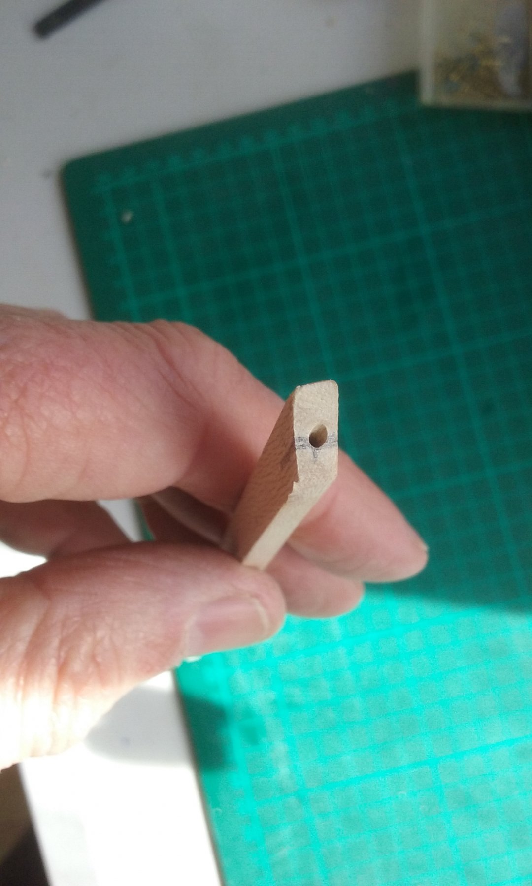
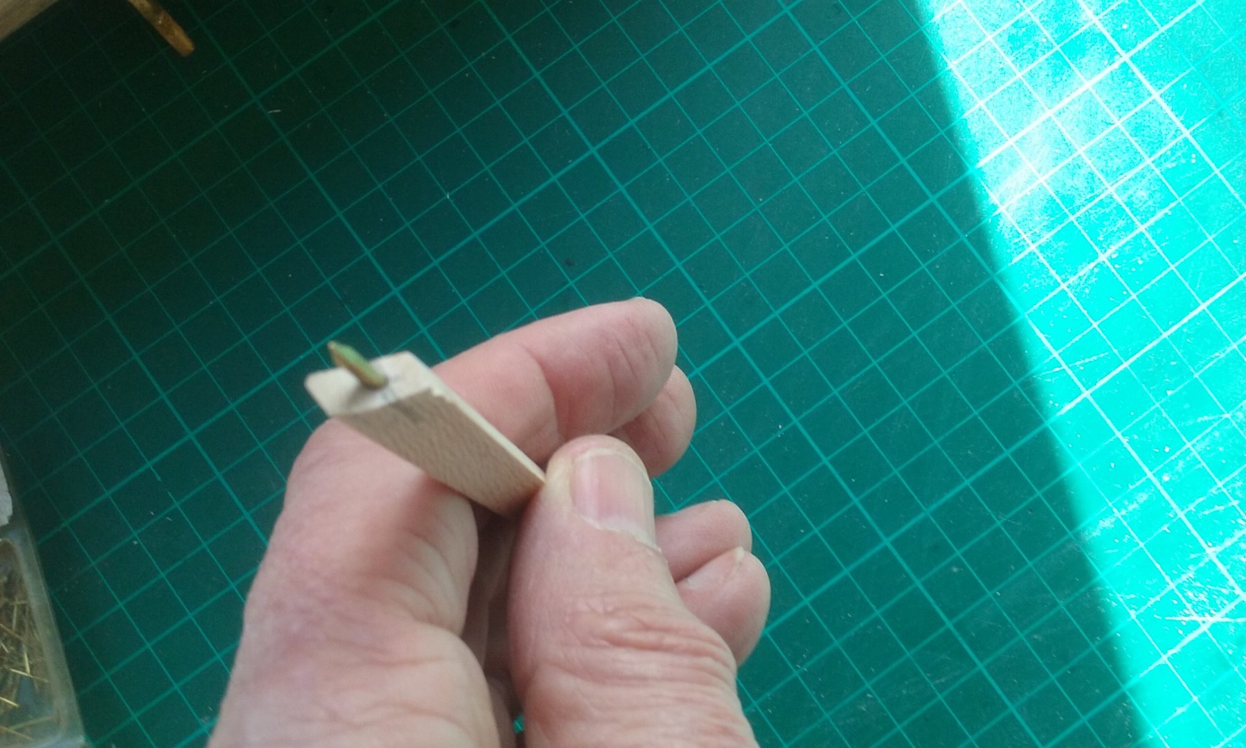
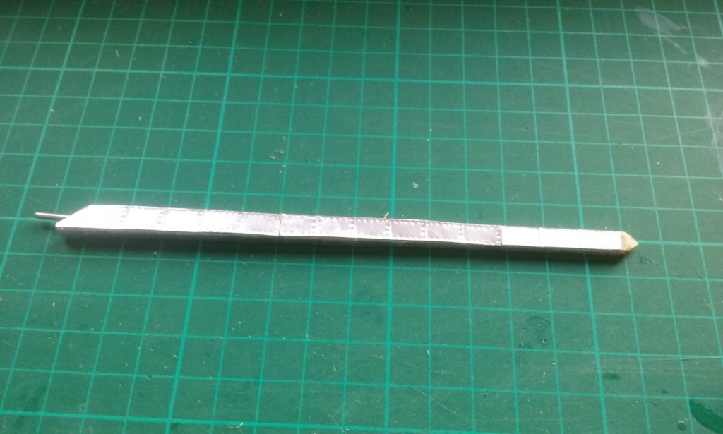
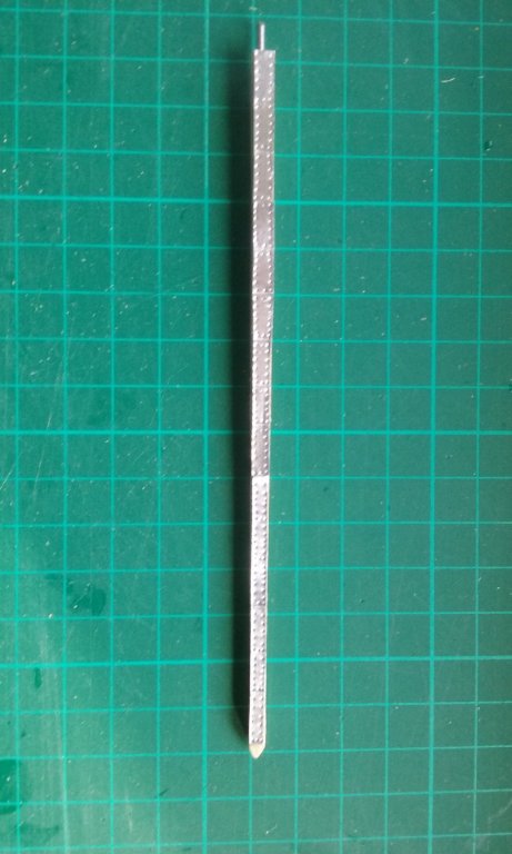
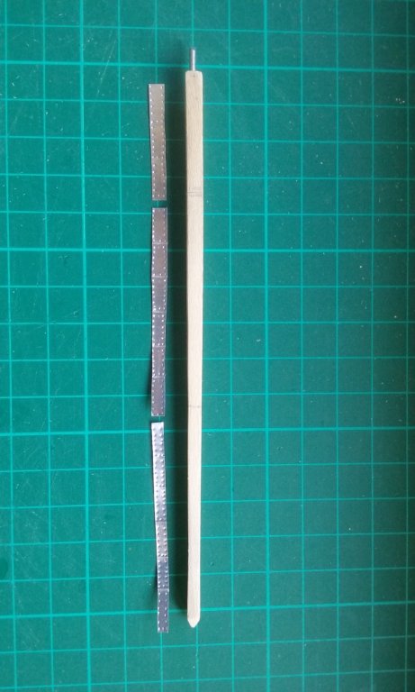
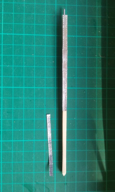
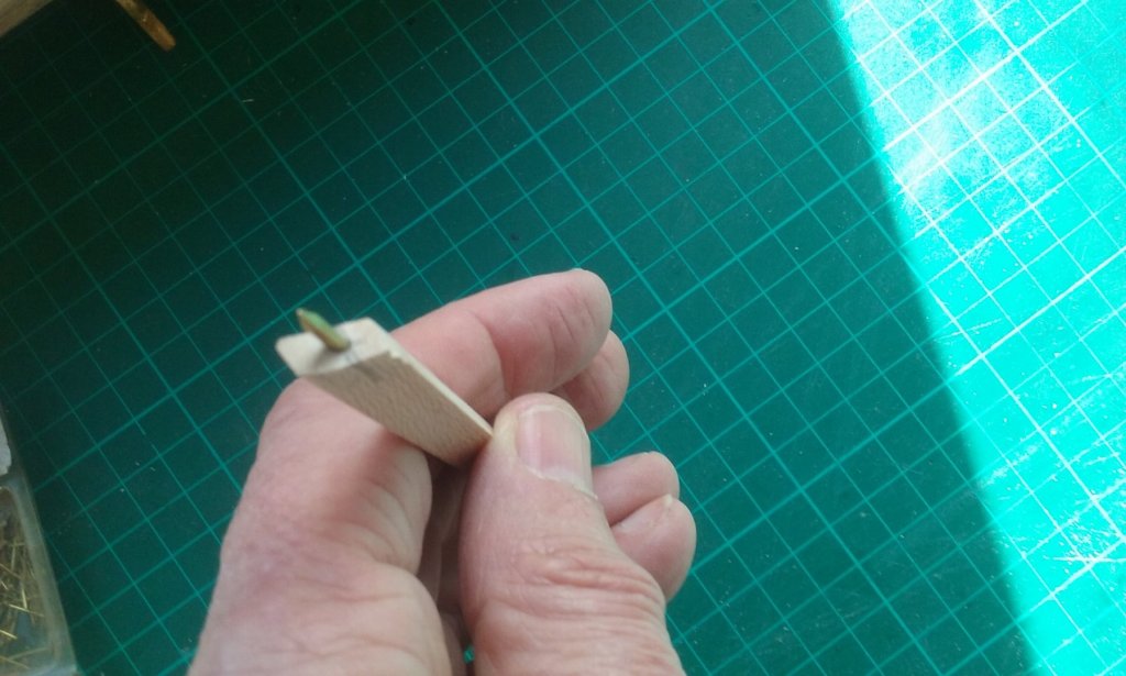
Spur made and a 'trial' for the katakorax made out of card from a cereal packet. This isn't complete - just one side made, but it could be the way to go so long as I can get it to look like metal. Thanks for the suggestion Carl. A hole drilled in the spur and a corresponding hole in the stempost, to fit a rod (a cut-off escutcheon pin) to enable the two pieces to engage with each other. Having a bit of trouble finding foil of the correct thickness to simulate the metal cladding. My wonderful wife suggested the foil seal you get on the top of a tin of Milo (like Ovaltine, only Australian). Looks like I'll just have to grit my teeth and force myself to drink Milo (it's a rubbish job, but somebody has to do it 😉 ) Steven


-
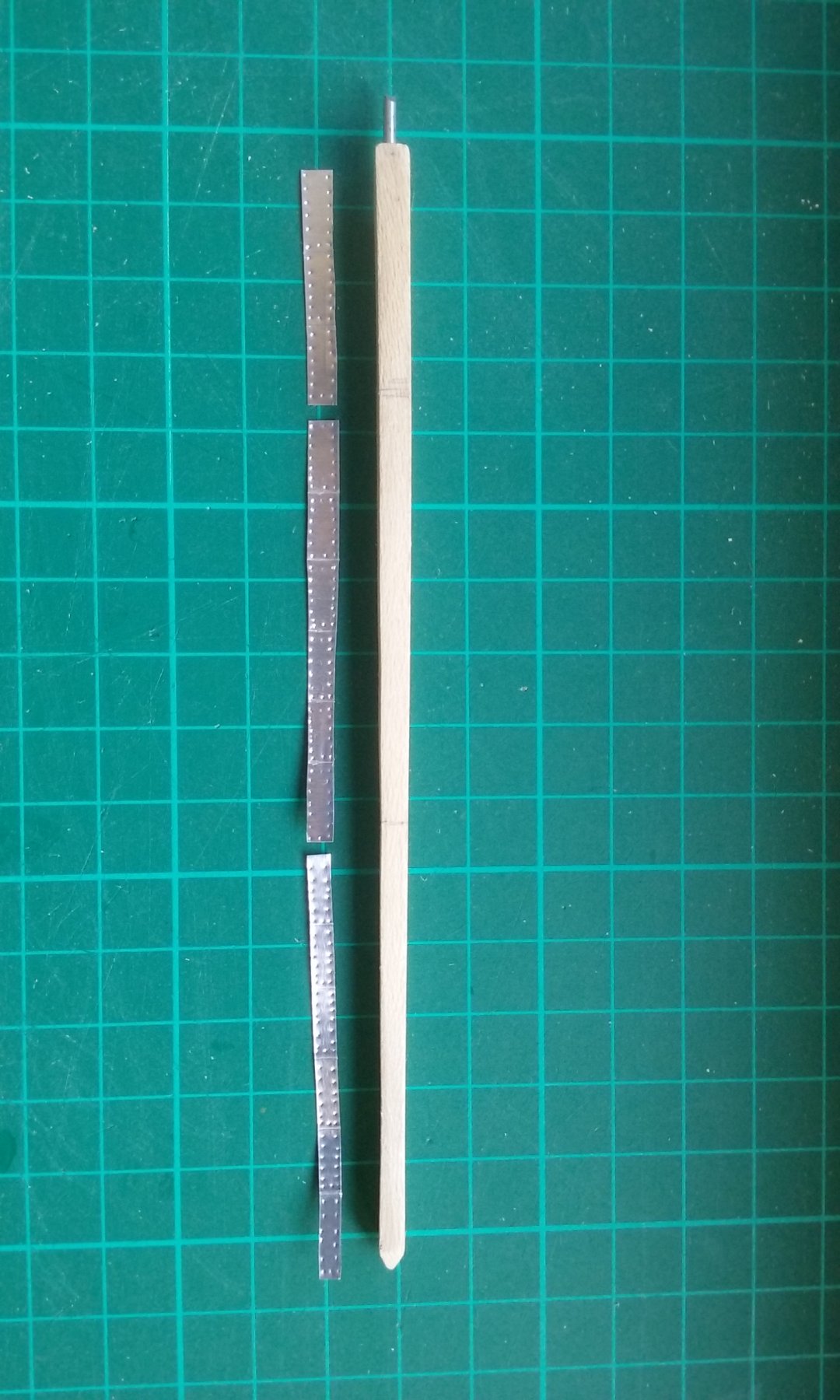
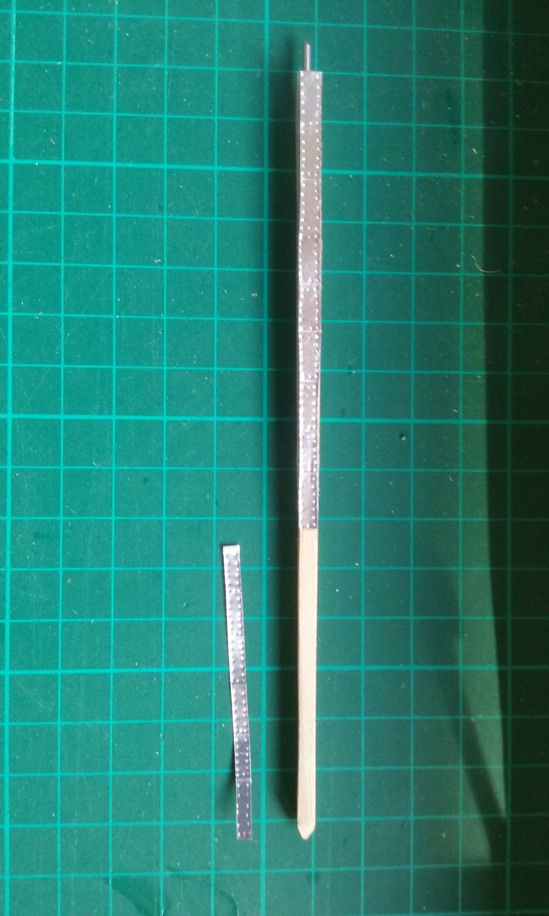
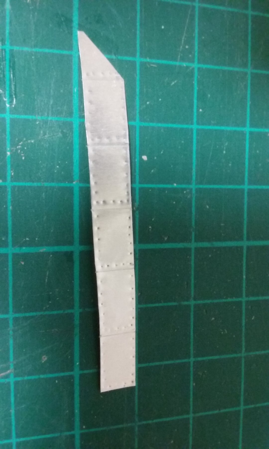
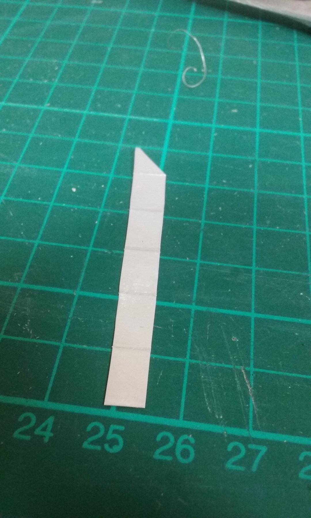
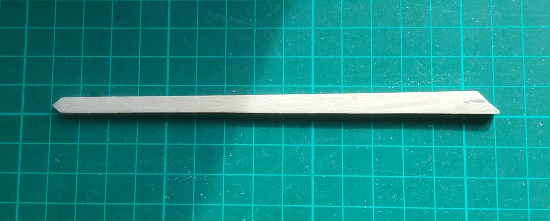
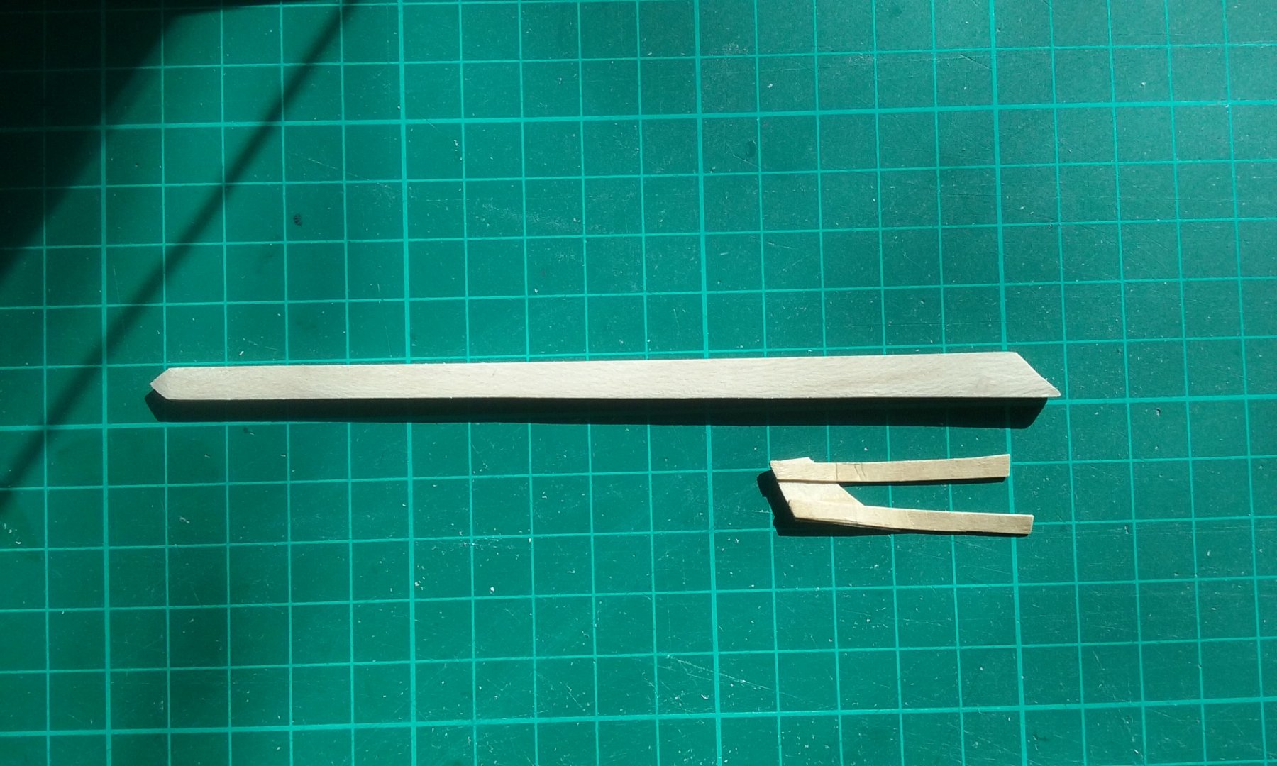
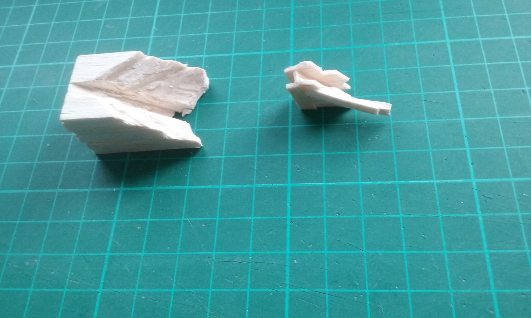
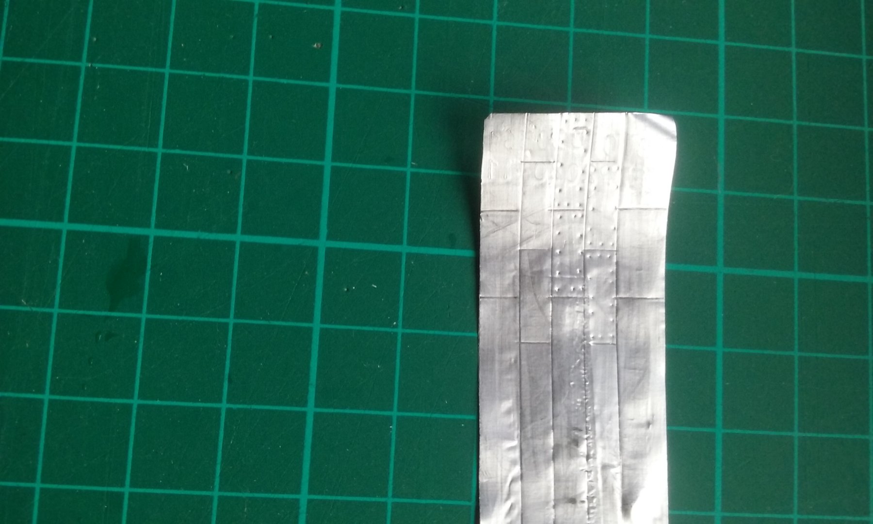
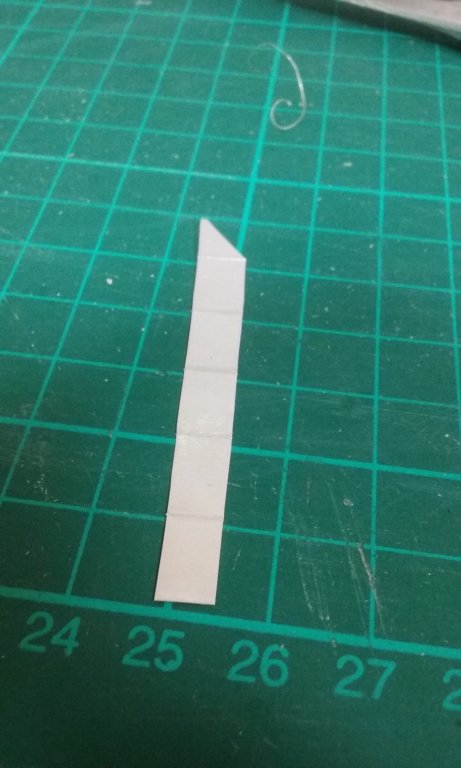
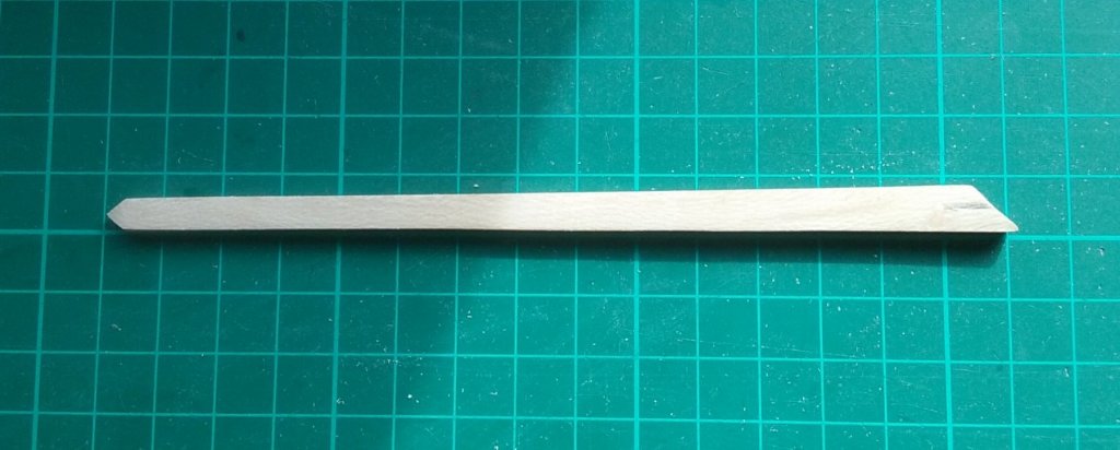
I've been working on the spur, doing test pieces for the katakorax (connector) and the protective metal cladding. Here are a couple of ideas for the katakorax, both made of balsa. The left hand one is carved out of a single block to take the shape of the bow, with the idea of then carving the outside to make the katakorax itself. The right hand one is made of individual pieces glued together. If successful, I'd then use pear wood and I'd probably then have to cast them to make them look like metal. I'm not terribly happy with either one, and I'm thinking of making it out of sculpy instead. Once done it should already look like metal. The reason I haven't tried it in brass is that I'm no good at soldering. And here's my test piece for the metal cladding. A bit rough and ready, but it was just to see if it could be done. I've used the foil packaging the No. 11 scalpel blade comes in. It's thicker than kitchen foil, but does have the disadvantage of having to smooth out embossed lettering and the outline of the paper behind the scalpel blade. If I can get "virgin" foil to this thickness I'll be a lot happier. Steven


-
Thanks for all the likes. Druxey, yes, having the ram holding the ships together would certainly facilitate boarding. Cog, as the spur isn't on the waterline it's not likely to sink the enemy ship. The only circumstance I can think of where the enemy ship would sink is where the spur rides up and over it to capsize it. And unless it goes through the upper works rather than over them, that shouldn't be a problem. However, if it did get caught in the upper works as the enemy ship rolled . . . Roger, I'd heard the term "breast hook" but never bothered to find out what they were. I think they must certainly have been used in a design like this. Thanks for the tip. And yes I agree a spur would have been rather unwieldy, just in normal sailing. In fact one of the reasons I'm in favour of the higher spur rather than waterline is the idea of what a 10 metre spur (or even 7 metres) sticking out at water level would do to the handling of the ship. Thanks also for the quotes. Whether the spur was used as a boarding bridge, if it was resting on (or protruding through) the enemy's upper works after ramming, it would make boarding much more advantageous. It's been determined pretty much for certain that a galley of the 10th to 12th centuries didn't have an apostis, but the principle is the same. Steven
-
Very nice work, Radek. I used to have the book "The Voyage of the Mayflower II". Very enjoyable, but got lost sometime during one of my housemovings. A pity; I used to re-read it every so often. The 1957 reconstruction and voyage are a saga in their own right. You'r doing a very good job of her. Steven