
captain_hook
-
Posts
675 -
Joined
-
Last visited
Content Type
Profiles
Forums
Gallery
Events
Posts posted by captain_hook
-
-
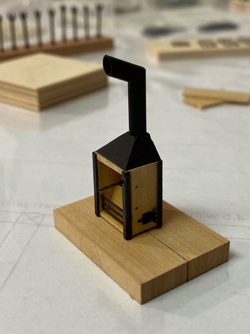
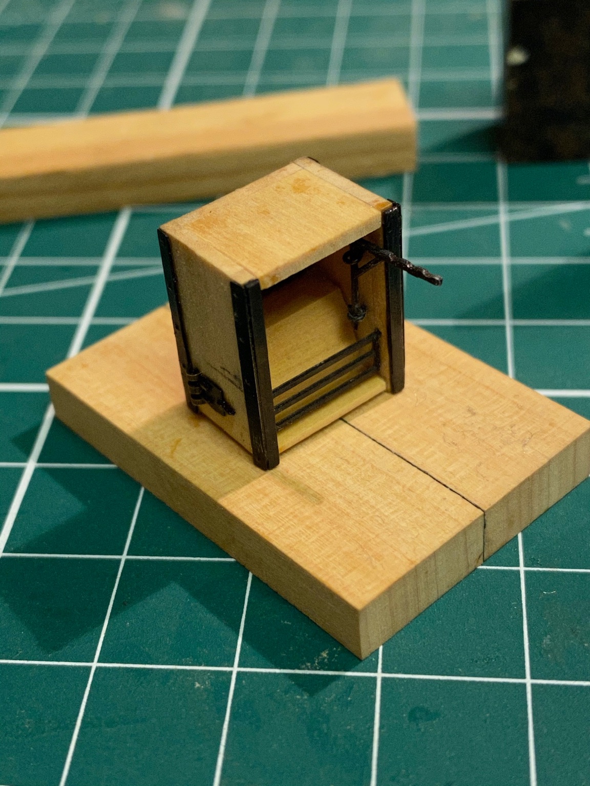
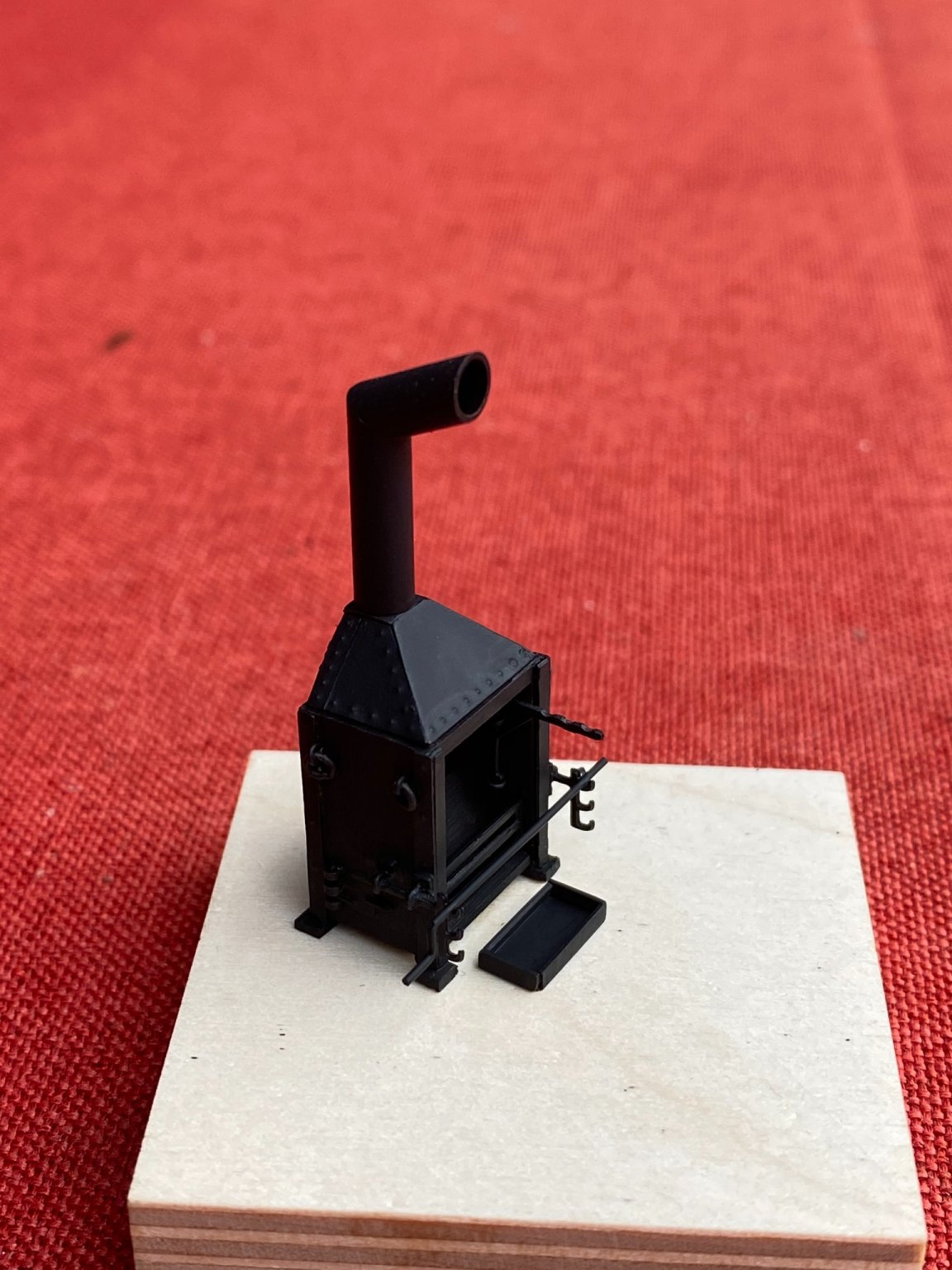
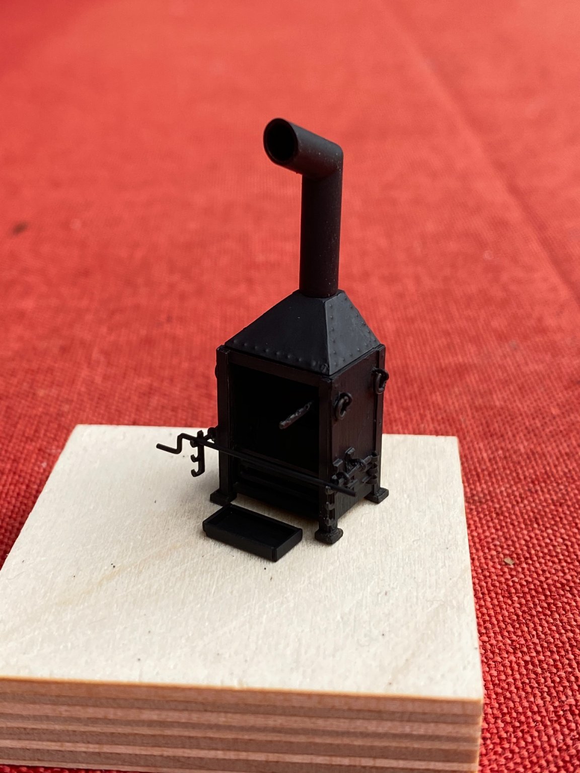
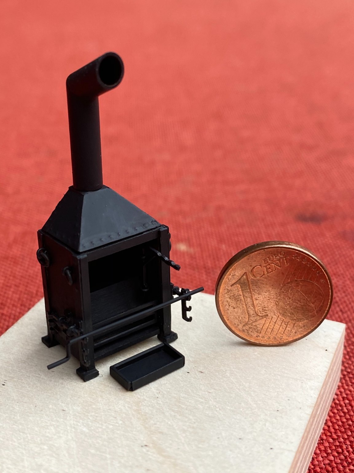
Building time is limited these days so before I start more work on the hull I wanted to do a little side project, the ship‘s oven. As a reference I used a picture I found on MSW in another thread. It was rescaled to match the scale of the build.
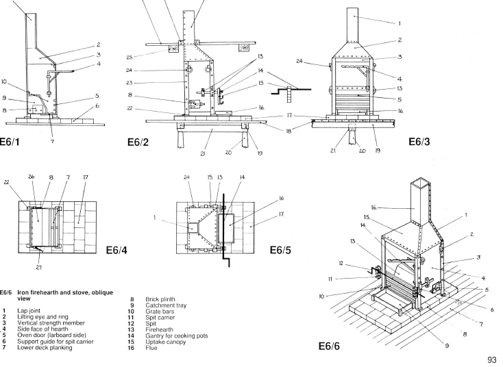
The original kit supplied one is just a box made of britannia casting and the chimney is attached to it. I started with building the basic structure made of wood. The assembly is basically made of boxwood sheets with some brass parts attached to it with epoxy.
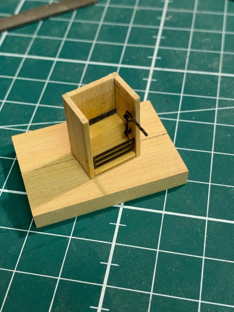
Then the brass parts were attached. Put the whole assembly in my electrical stove after attaching the parts to each side and heated it for 10 min. (100 C Celsius) to reduce the cure time of epoxy.

Instead of an angular chimney I decided to use a rounded one to match the one in my plans.
The whole assembly with all parts attached to it but without paint.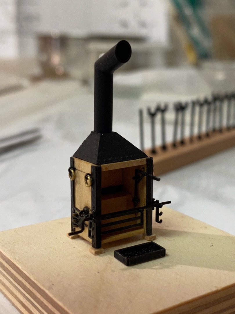
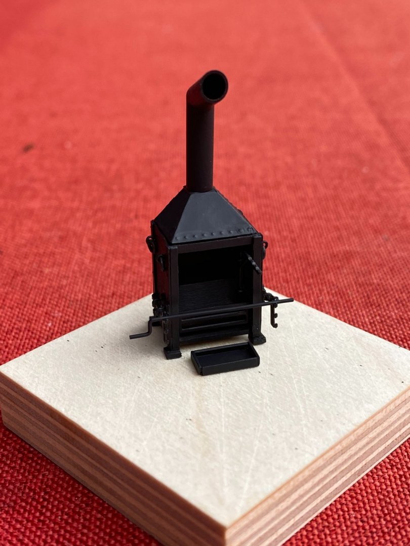
... and after painting it with oxid black acrylic. Will add some clear vanish just before final installation.


-
-
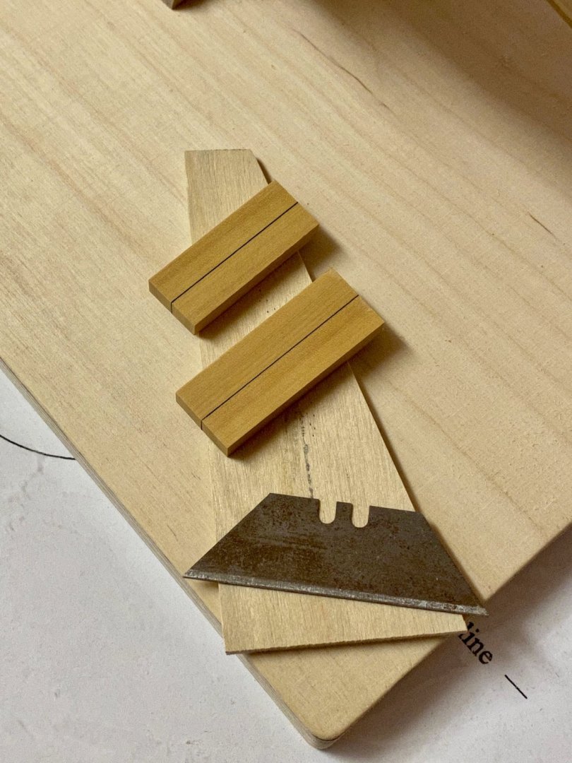
Some weeks have passed and I finally was able to spend more time in the workshop. For simulating tarred joints I first glued the paper on one of the two parts that are joined later. I use two different paper weights (80 gsm and 20 gsm) to simulate different strength of joints. As I haven’t found enough information about all keel parts and how it was build I finally decided to paint the hull white below the waterline so I only have to build the knee. It is exactly shown on the NMM plan. For the keel I will use a single part.
Holes were drilled into the paper so the glue can penetrate the wood on the opposite parts.
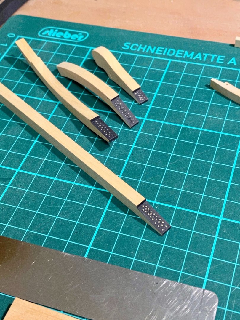
Both parts were then glued together to form a joint.
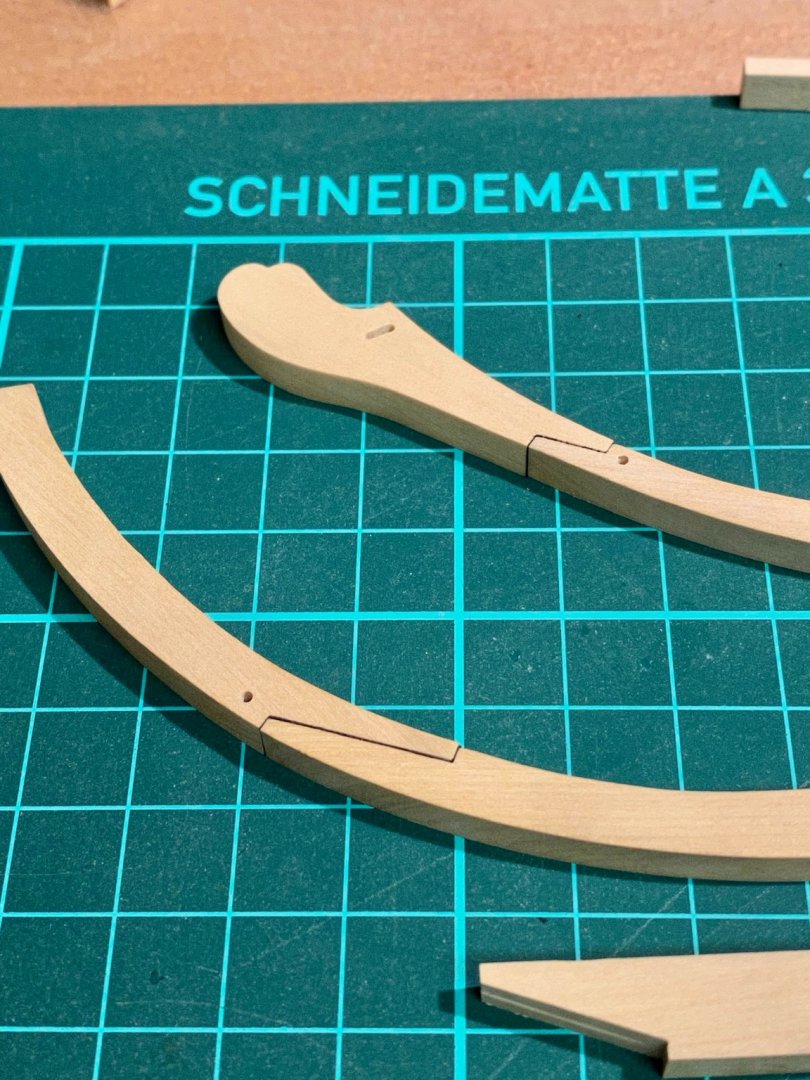
Both sections were then glued together to form the knee. Another layer of paper was used to separate both sections.

The keel was added at last.
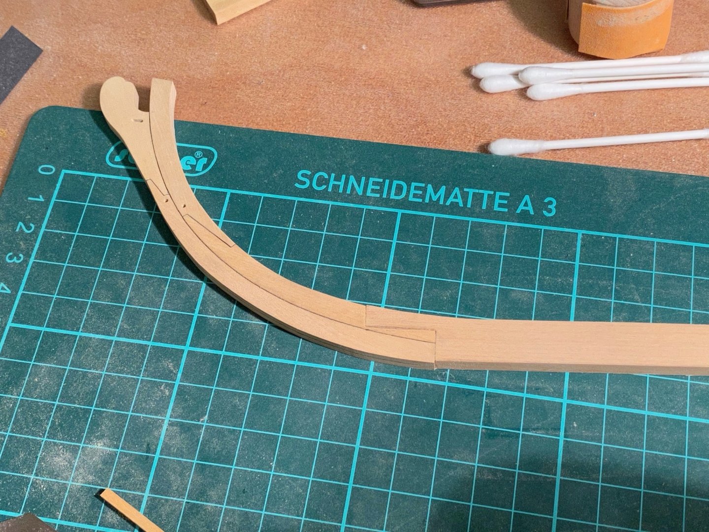
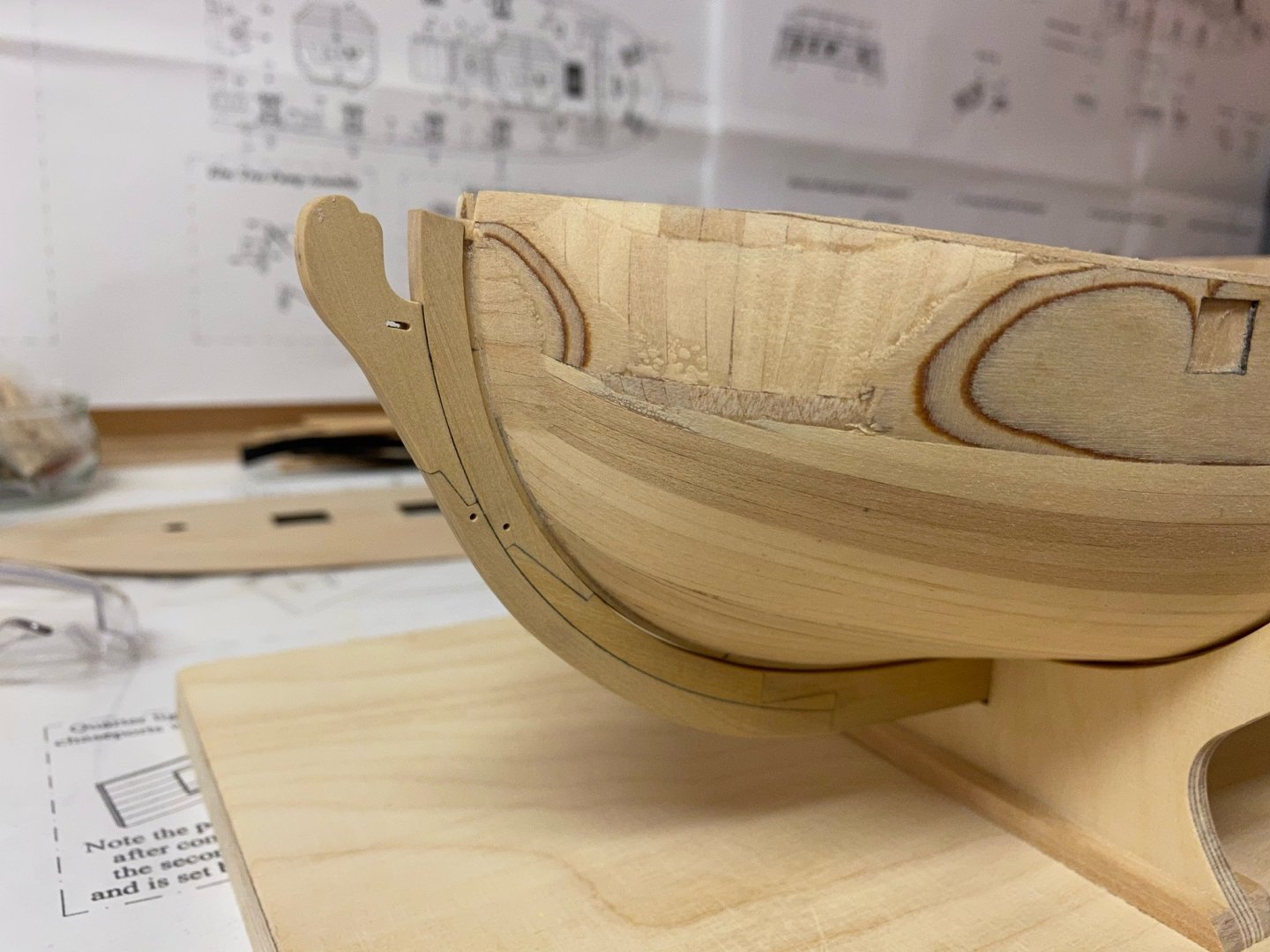
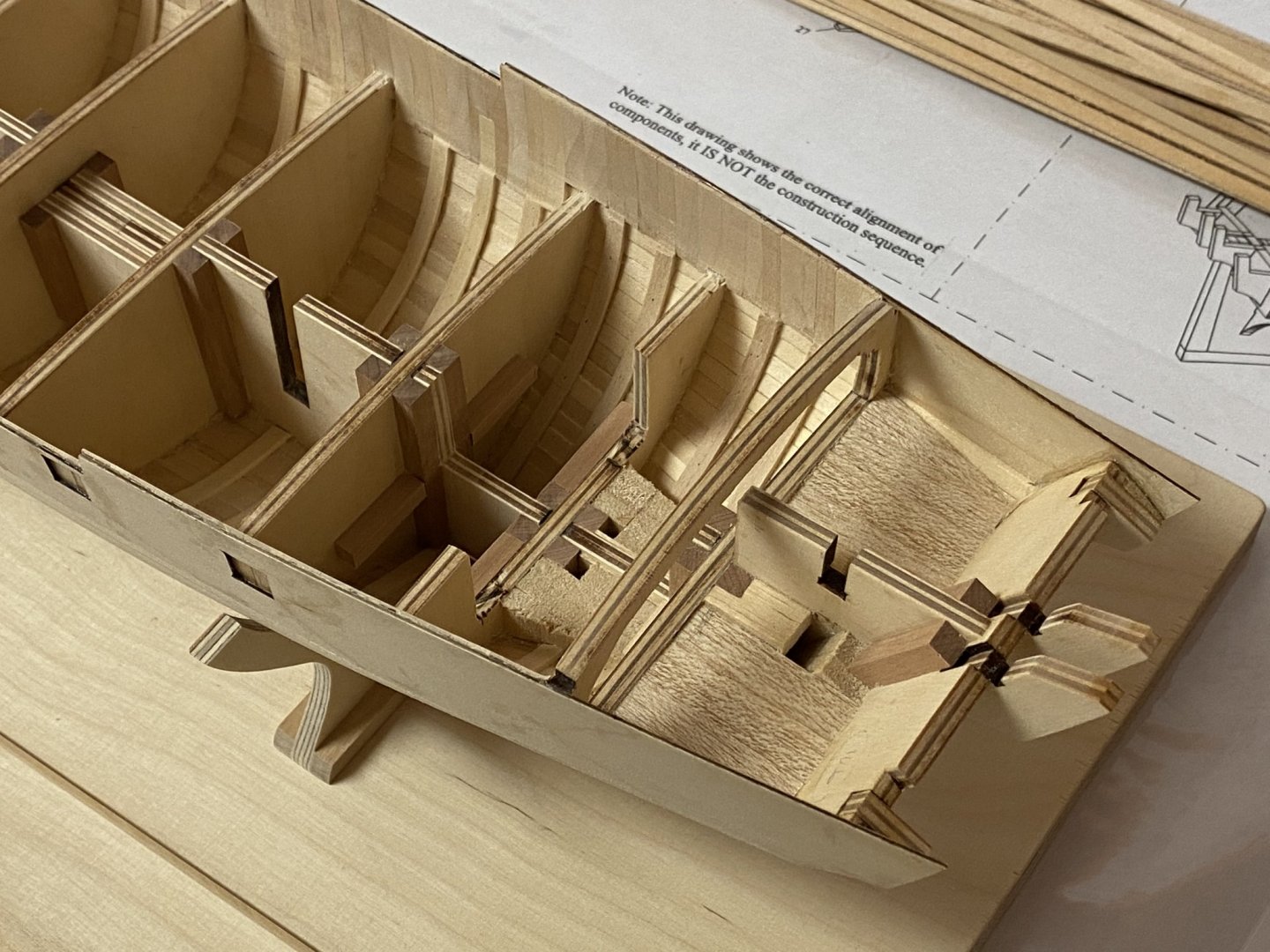
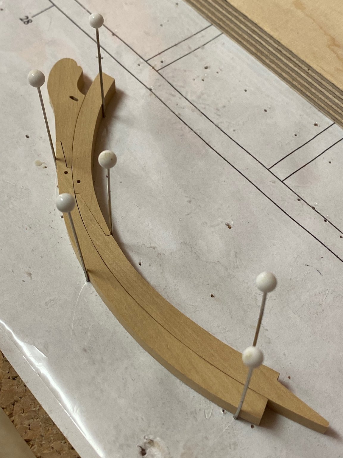
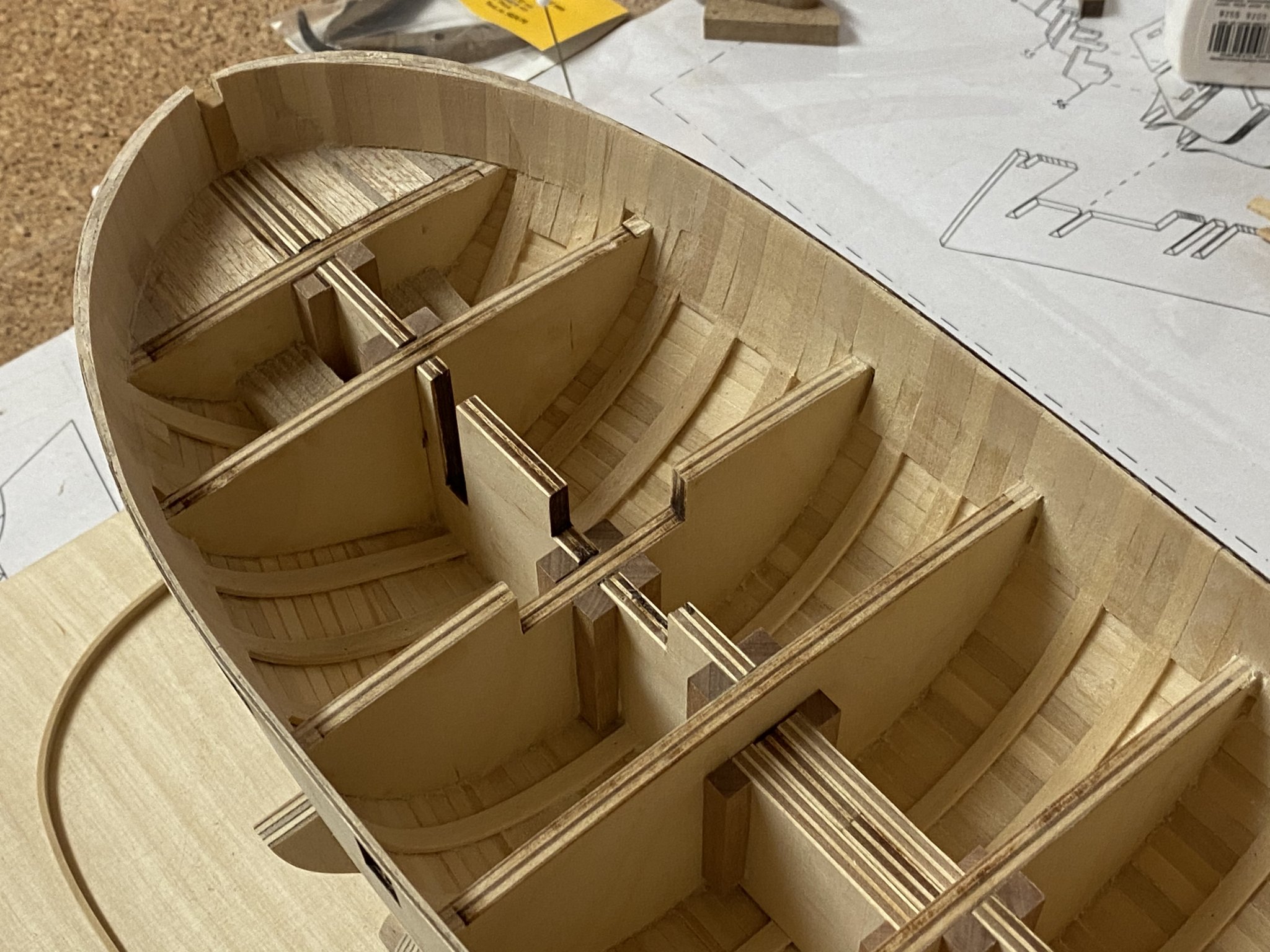
Dry-fit on the model. I still have to taper the knee and cut the gunports before the keel will be glued on.
-
-
Fantastic build and interesting subject!
-
-
Hello everyone,
now I have some wood in stock I think about expanding my tools-setup to cut sheets and strips myself. I have already decided to buy a Byrnes saw but I‘m not sure which accessoires are useful too. I will surely add a metric micrometer-stop and another 3‘‘ kerf. I understand that every accessoire has its own usefulness but maybe my english and my knowledge of tools is incomplete. Can anyone tell me please what a Rip Fence, a Rip Taper Gage and a Miter Bar are used for?
Best regards,
Andreas
-
Very nice, Jean-Paul. I also had to fix one swivel-gun stock, did all of them analog to the plan but unfortunately one interfered with a deadeye.
-
Nice build and rigging! The Cruizer-class brig is one of my favorites.
-
Very beautiful! I also vote for marple, but it may be another option to paint the support red to optically separate the boat from the simulated deck and add more warm colour, especially if you will use an acrylic case later.
- BobG, FriedClams and JpR62
-
 3
3
-
-
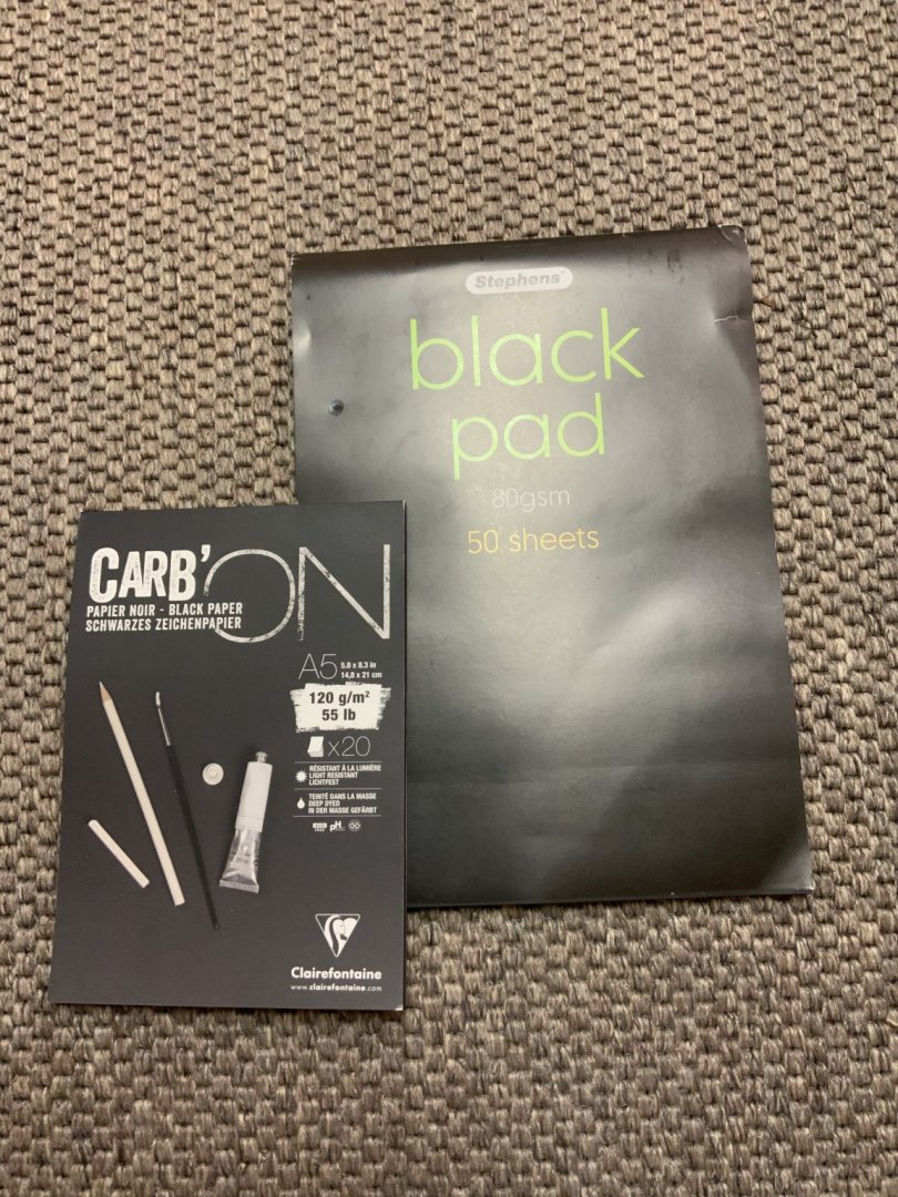
I made two test-joints with scrap. The one in the back is made with black paper (80 gsm), the one in the front is made with black single-sheet cellulose (maybe 30 gsm) I „borrought“ from my daughters desk. Both look very similar but the one in the front looks more discrete. Nitrocellulose-lacquer was used as varnish.
- GrandpaPhil, JpR62, mtaylor and 4 others
-
7
-
Thank you barkeater, I agree to that. I have finished all eight keel pieces and dry-fitted them. Got some 80 gsm and 120 gsm black acid free paper and I will try the simulated tarred joints on some scrap parts first.
Anyone has a suggestion how to taper the „knee of the head“? I have only seen that on some bigger ships before but these ships’s had a different shape. The Speedwell and the Fair American seem to have a similar KOTH, maybe I should use them for reference.


- mtaylor, GuntherMT, GrandpaPhil and 3 others
-
6
-
Nice work so far. Do you plan to add some decorations like sheer rails?
-
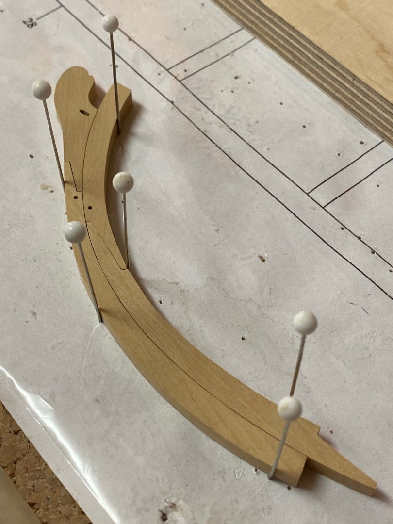
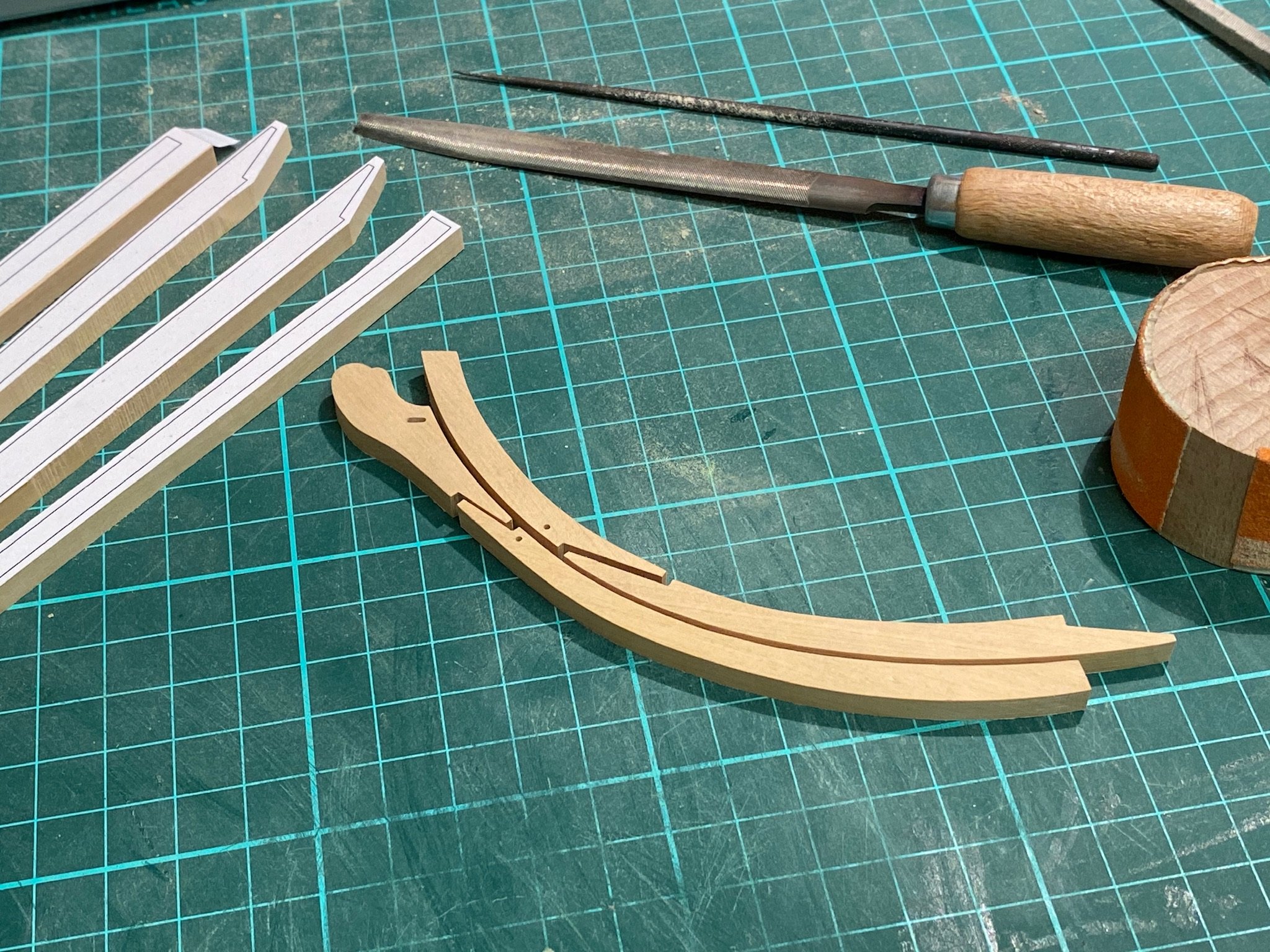
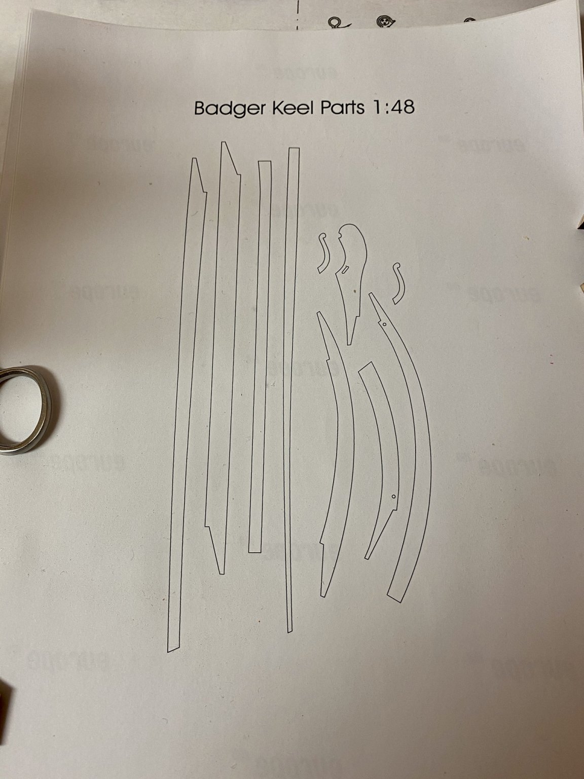
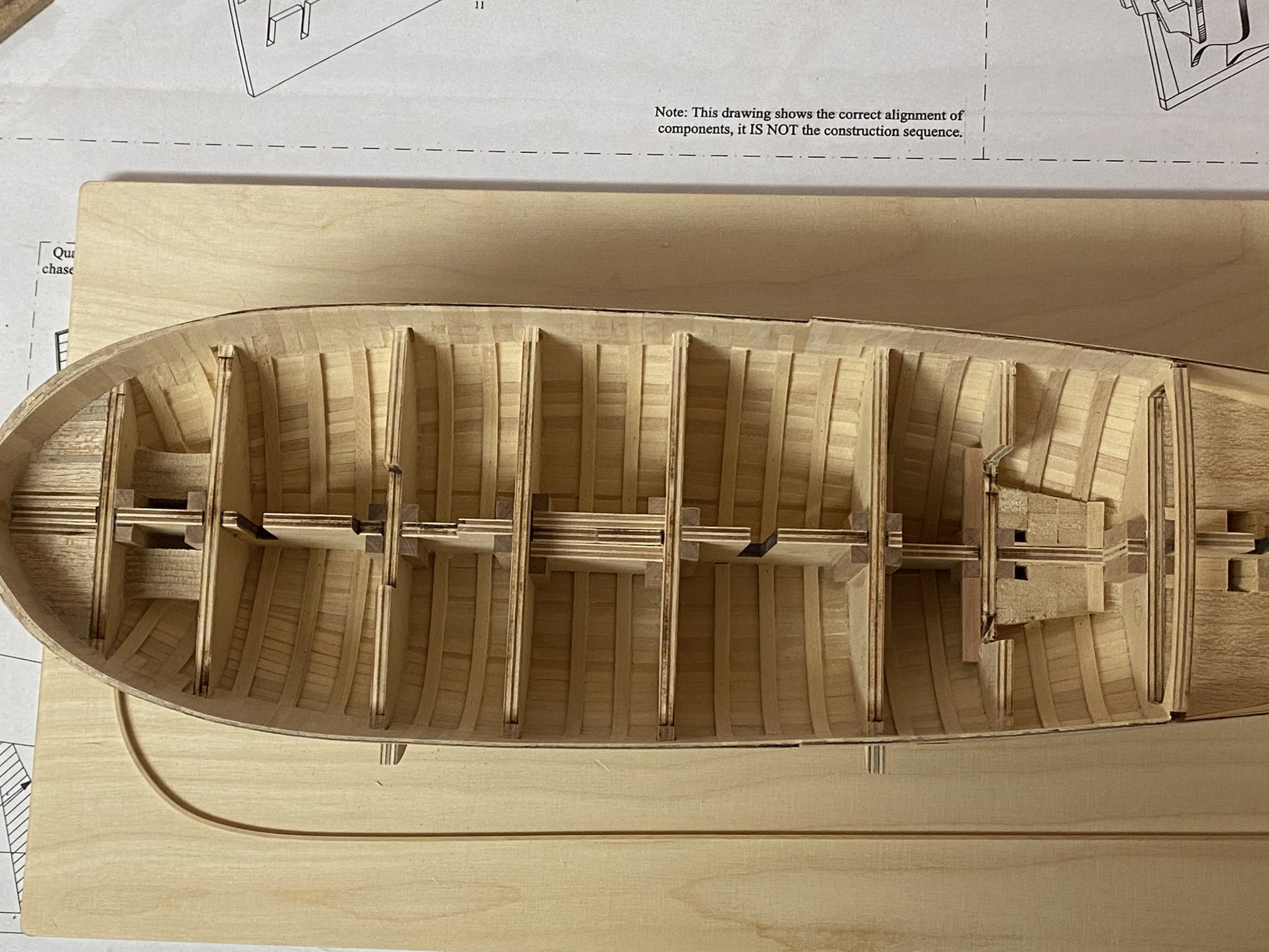
Thank you for the nice comments and the likes. The original kit supplied a simple 2-part keel for the Badger as it is supposed to be painted later. The NMM-plan shows a more complex multi-piece keel and I’m going to prepare both options to choose the final one later and gain more experience for future builds. For the multi-piece solution I first printed all parts on adhesive paper and glued them on 7/32“ boxwood sheets. Then roughly cut the parts with a scroll-saw and sanded them to shape with a Proxxon disc sander.
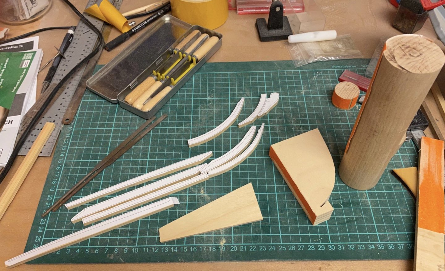
The final sanding to snug fit was done with sanding blocks I made of different wooden blocks. The sanding paper is attached to the blocks with double-adhesive tape and the bottom of the blocks is sanded with the disc-sander so the attached sanding paper is orthogonal to the bottom of the blocks to secure no sloping will occur during sanding the keel parts.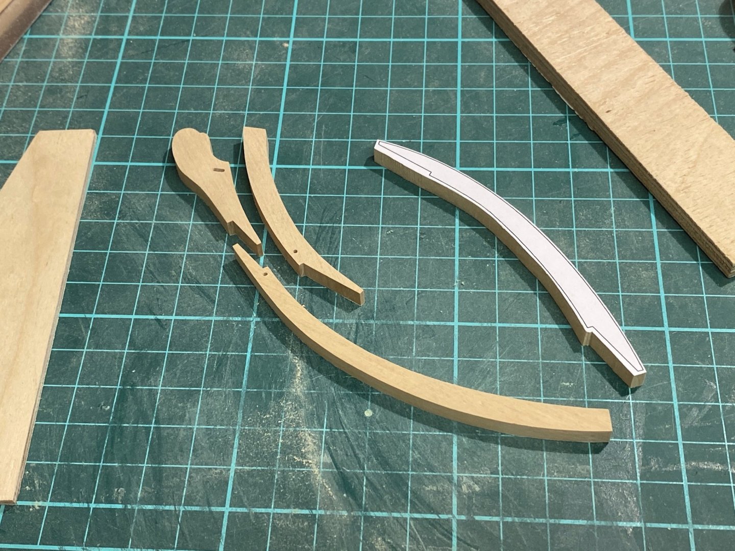

As the paper templates are still on I have to use some needles for a test fit.
For the tarred joints I might try the paper method dvm27 explained pretty well in his Speedwell log. But before gluing all parts together I still have to find out how to taper the keel correctly. As this is my last day at home working in my workshop might slow down a bit during the next weeks.
-
-
Very nice! Did that ship really had a lion as figurehead or is it some sort of placeholder?
- mtaylor, FriedClams, Keith Black and 1 other
-
4
-
Nice work Jean-Paul, looks very good. The rigging of the AVS I had the most trouble with were the stays (bob-, fore- and backstays) because their tackles are supposed to be seized and fixed. So I ended up doing all them twice because I had to readjust the tension after some time. If I had to do them again I would prepare but not finish them until bowsprit and mast were in place and then adjust to final tension.
-
-
Thank you barkeater. I have sanded the bulkwards to shape at the bow. This project will be a challenge. The gunports are way off compared to the NMM plans so I will ignore the cutouts and cut new ones by hand. Have added the rabbit and drawn the keel parts with Corel Draw. Printed them on adhesive paper to cut them out of boxwood sheet later.

- Edwardkenway, GuntherMT, Kevin and 5 others
-
8
-
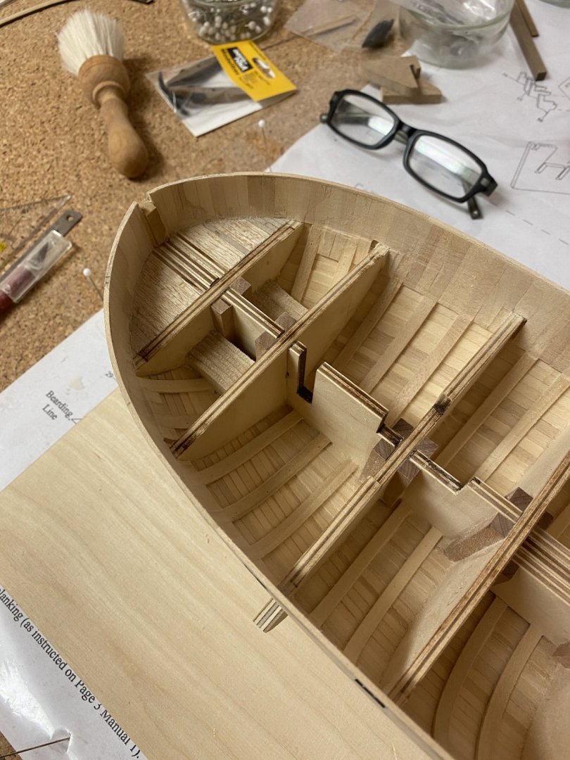
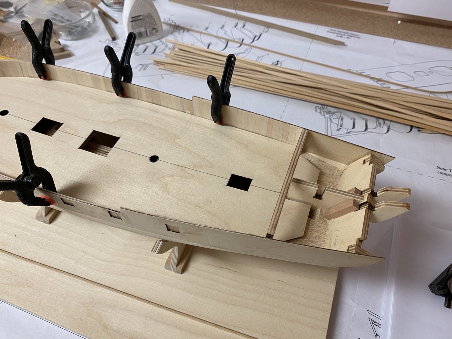
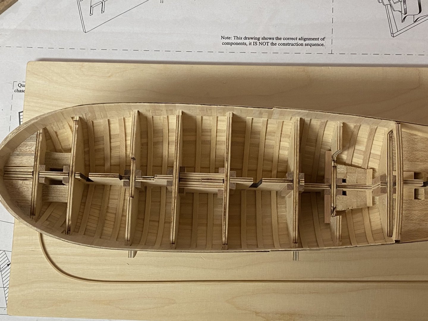
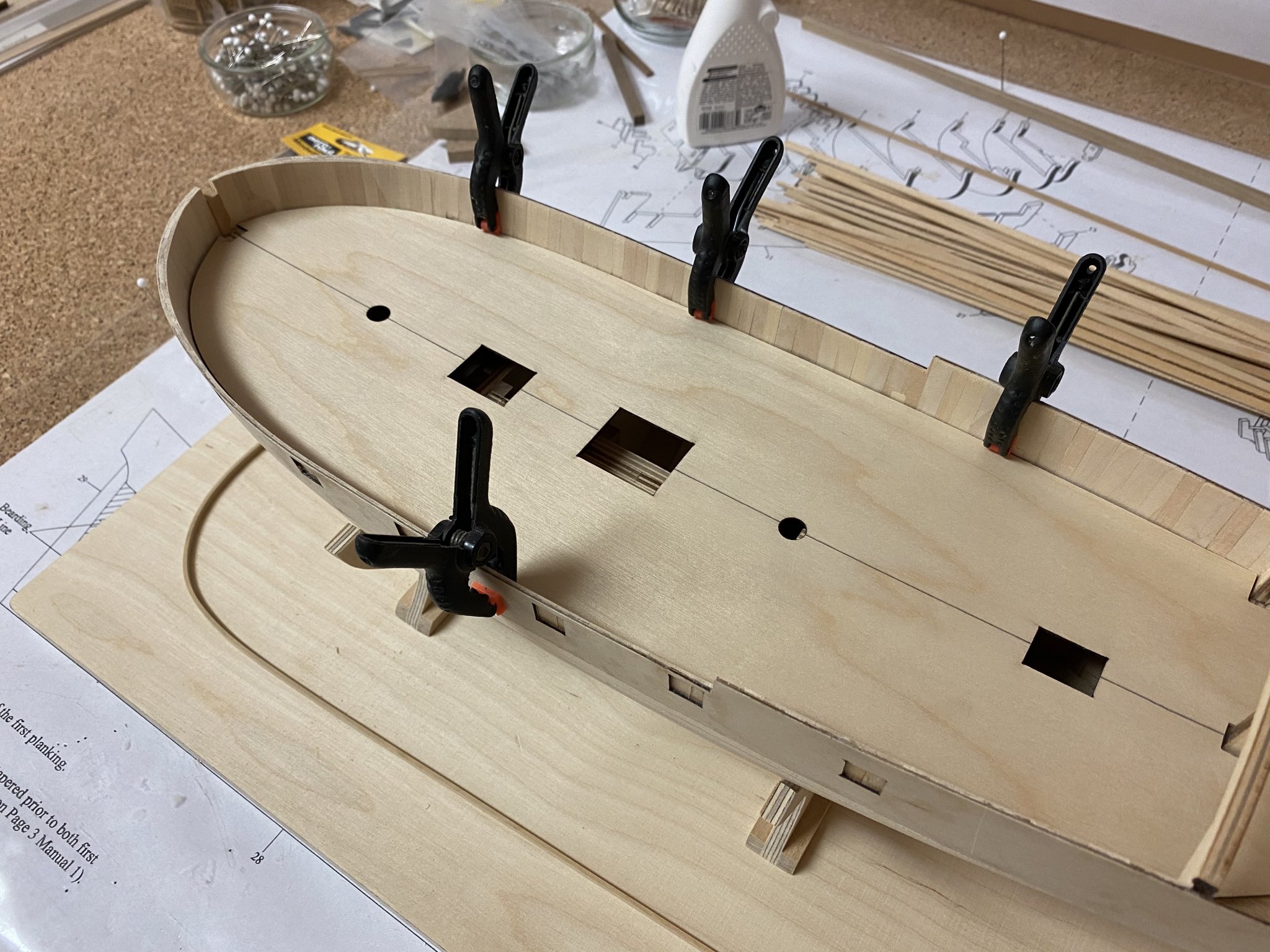
The plywood false deck has been dry-fitted. As it is not glued yet I have to fix it in position with some clamps.

- GuntherMT, Edwardkenway, mtaylor and 3 others
-
6
-
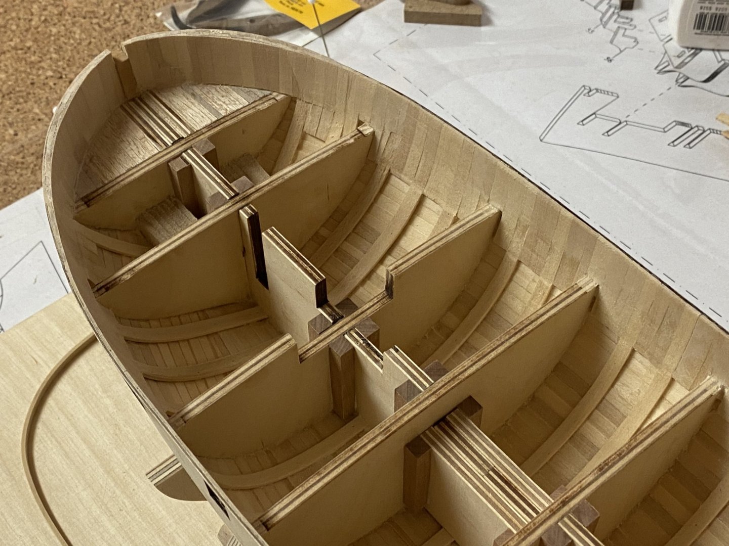
The use of gunport pattern might not have been the best idea. Should have planked that area with basswood stripes instead. As the plywood gunport pattern is more than 2 cm wide and 1,2mm thick it is not very flexible and the upper edge has the tendency to warp towards the outside at the bow when bend around the first two bulkheads. So I had to fill that area with small basswood stripes to compensate. These fillers are beveled so they are 1,5 mm at the top and almost as thin as a hair at the bottom. They are glued inside the plywood to strengthen the plywood and to form a new first planking so I can sand down the plywood without the risk of weakening the structure too much. So the bulkwards at the bow are now almost orthogonal to the deck. The bulkhead extensions have been removed and I reinforced the plywood with 1,2mm basswood stripes so it will hold its shape and to make the bulkwards a little stronger. Sanded them down to 0,8mm. Still have to sand down the outside bow areas.
- GuntherMT, Edwardkenway, Ronald-V and 3 others
-
6
-
-
Very beautiful model! Congratulations! 🎉
- abelson, JpR62 and Ryland Craze
-
3


HM Brig Badger by captain_hook - Scale 1/48 - Modified from Caldercraft plans
in - Build logs for subjects built 1751 - 1800
Posted
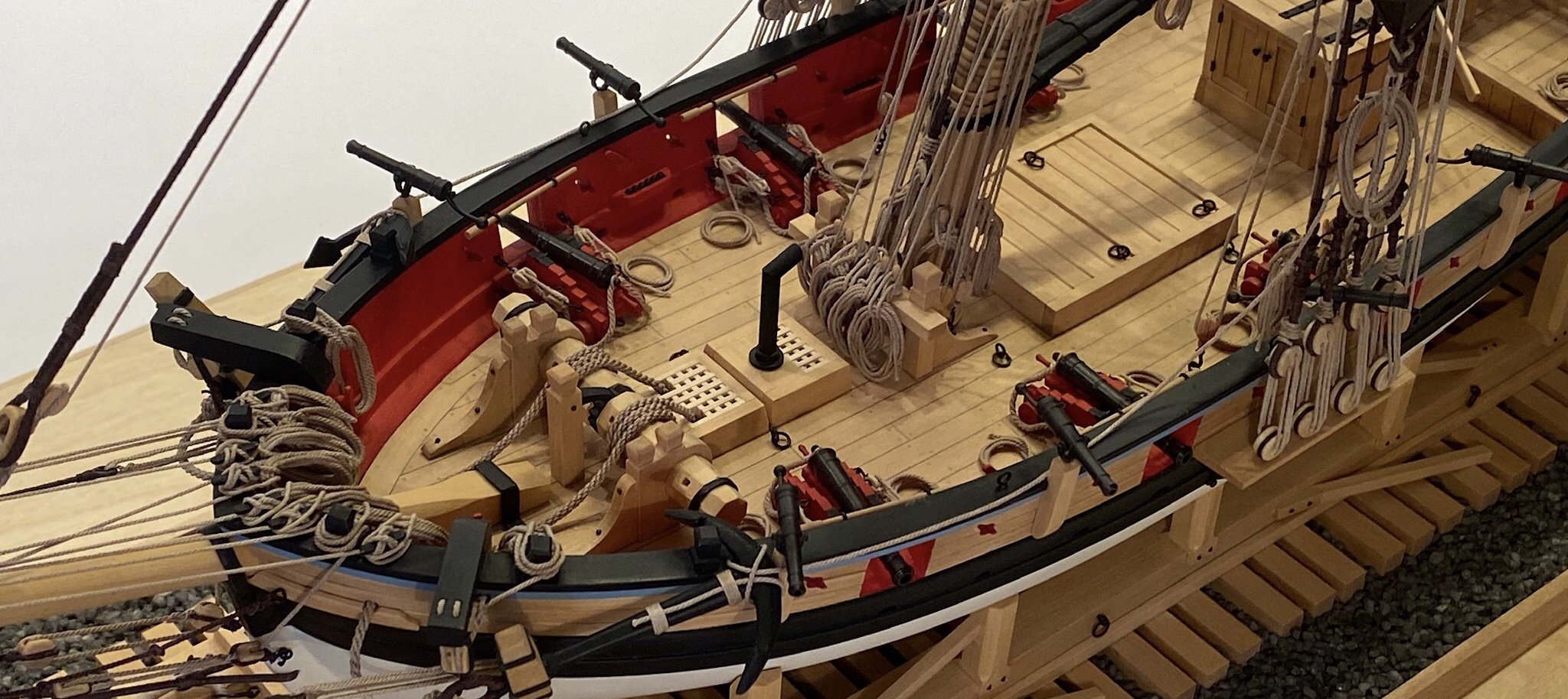
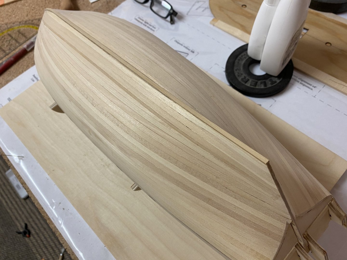
Prepairing all fittings slowed me down during my last build but this time I have already prepaired them all. Now back to the hull. I glued all subdecks in place and then the false deck.