Thistle17
-
Posts
1,054 -
Joined
-
Last visited
Content Type
Profiles
Forums
Gallery
Events
Everything posted by Thistle17
-

Atlantis by Thistle17 - FINISHED - Robbe
Thistle17 replied to Thistle17's topic in RC Kits & Scratch building
The saga continues! In marking out the masts I discovered that the main is about 20 mm too long and the fore is about that dimension too short! I guess I was so happy to have Krick of Germany support me I never checked the measurements. So now the question is can I get away without some surgery. I am concerned that the sail patterns just won't match the stay and mast outlines and look a bit out of kilter. In a cursory check the foreshortened fore has enough "top" clearance that the 20 mm difference will still handle the sail. Secondly I have decided to completely rig it in my shop and transport it to it's final destination with the masts stepped. I have to travel about 35 miles south of Rochester NY and up the side of a very steep and poor road to its final hill top home. Stepping the masts seems the best alternative. Here is how I plan to move forward. We have a great RC shop in our town and they carry an extensive line of DU-BRO fittings for all type of RC models. I was introduced to what is called "2-56 Push Pull System" that will facilitate shrouds to be made up and then disconnected. The kit comes with crimping sleeves and shrink tubing to dress over the crimps. The kit also comes with nylon coated stainless steel braid of the right diameter as well. For the fore and aft stays I just ordered turnbuckles of the right scale to further enable mast stepping. Some running rigging for the booms will need to be considered (made up and then removed, belayed at site) but should be achievable. In addition, there is a clever mast shroud tightening mechanism built into the kit so I think I can make it all happen.....I hope. The world of RC modeling is a world unto itself. I do have an electronics background but even so there is so much to learn. I am quite relieved that the client wants this to be a static model! Joe -
Poor Man's Lathe disasters
Thistle17 replied to stevenmh's topic in Modeling tools and Workshop Equipment
Steve I have had the same experience on my full sized lathe. I was turning a 3/4 birch dowel down to, I hoped, 1/2 inch because I just needed a few inches and it shredded as yours did. I ended up buying the right dowel. When a piece like yours has too much force applied to the element perpendicular to the axis the fibers start to rip. You can try slowing down the drive (drill) and taking much lighter cuts. What I would recommend further is that you try using a file or sanding stick to the right diameter and then turn the shoulder. As for the material I hardly ever use kit stock as it is just not suitable in my judgement. Swiss pear, cherry, maple, mahogany and box turn beautifully. I'd pick one of those. Joe -
Chuck the good news is you have created quite a stir in the modeling community with your much sought after works. Sharing your work as you go was more than generous of you. The bad news is that it opens you up to everything from shouts of joy and encouragement to less complimentary feedback. It is in the human DNA and we all have experienced it. Stay the course and know that the vast majority in the community appreciate all you do! Joe
-
Atlantis by Thistle17 - FINISHED - Robbe
Thistle17 replied to Thistle17's topic in RC Kits & Scratch building
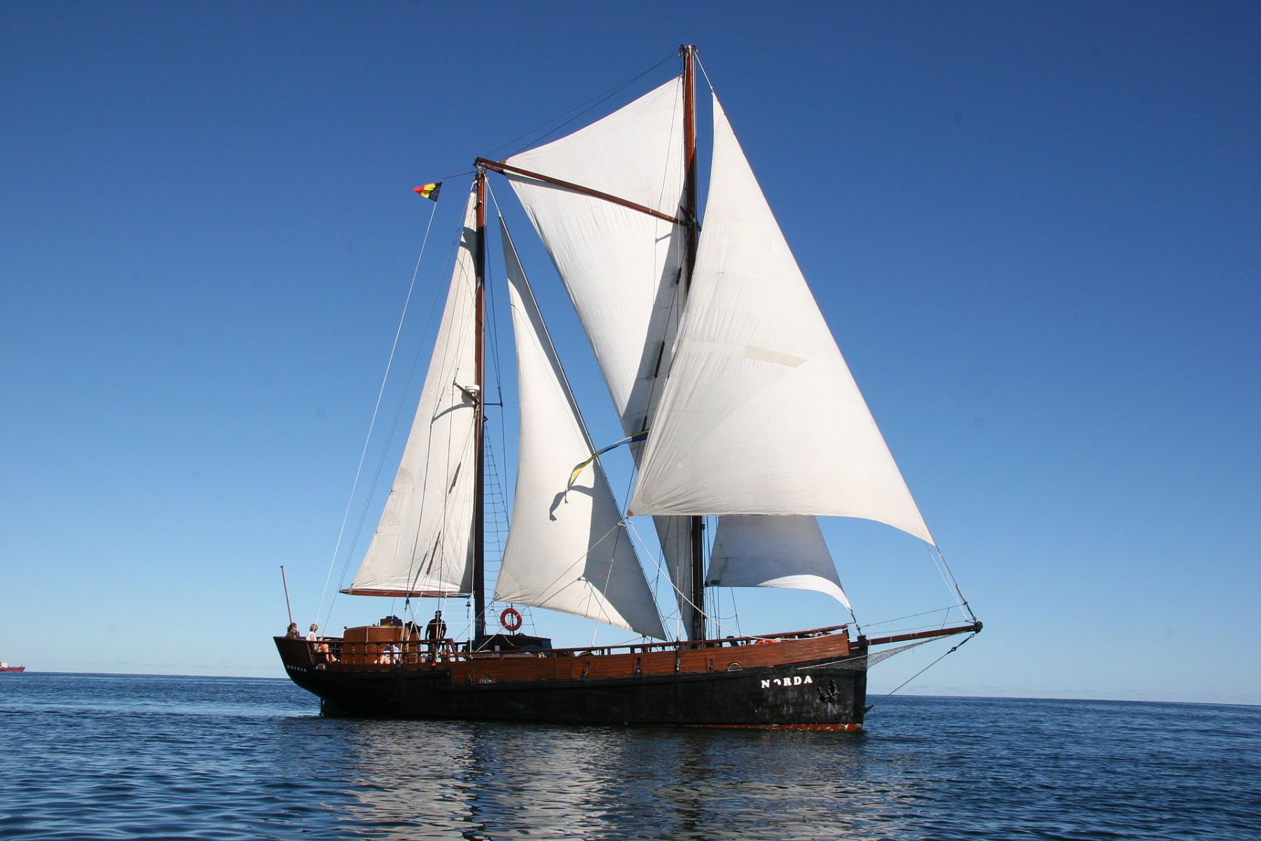
Thanks druxey and all others. I am beginning to think I may actually finish this model on time. I continue to find parts missing and poor, very poor instructions to confound my work. After I work up a sketch on running rigging I will tackle machining the aluminum masts and booms taking into account the RC versus the static rigging differences. I have attached a picture of the ketch I came across that is helping me along. In it is a good picture of the way a wish bone is attached and used. Joe
-
Atlantis by Thistle17 - FINISHED - Robbe
Thistle17 replied to Thistle17's topic in RC Kits & Scratch building
I don't think I have said this before but the rig on this boat is termed a "wish bone" schooner rig. Being just an arm chair sailor and only exposed to daysailers I had to research the rigging. Wikipedia was a decent reference and start point and there is a wonderful picture of a ketch, wishbone rig. The differences I have to address are the following: Atlantis is a schooner rig, it has a taller main than fore mast and it doesn't include a permanent attachment of the wish bone between masts. On the latter note I am motivated to make the wish bone permanently attached at this point. I am thinking this way as most of what I read describes the wish bone permanently attached and the sail is hoisted up in between the arms. So as a result I am going to sketch a running rigging plan and define tethering points on deck and that will further define a more appropriate fife rail. Joe -
Atlantis by Thistle17 - FINISHED - Robbe
Thistle17 replied to Thistle17's topic in RC Kits & Scratch building
I have begun installing deck fittings. At the moment I have installed and secured the fore and aft deck rings for stays (2 port and starboard for each mast. I have also drilled the deck holes for the 28 stanchions. While doing this I began thinking ahead about running rigging and it dawned on me that there is little,if any. I observed that there is no hauling rigging for forward and main sails, there are cleats to be affixed to the mast peak to "dress" the sail taught and secure it. This all makes sense now,as the only sail control meant for the model as an RC build was boom control. I perceive at the moment it should not be a major task to add sufficient running rigging. -
Kurt: Chuck should have the last word on this subject as he is obviously a master. But if you would like a basic overview, our model group has developed a primer on our web site on this subject. You will find it under RESOURCES/SHOP NOTES/LASER MACHINING. The site is modelshipwrightguildwny.org. It is by no means a comprehensive treatment but one could get started as the shop note suggests with Corel Draw. You should be aware that some pre-machining file examination, parameter setting and conversion is done by the operator before it is submitted to the laser knife. Hope this helps. I offer this in the spirit of sharing. Joe
-
Yes the transition from the bearding line to keel is a very gradual slope in the stern area. Make sure you have a very sharp 1/2" chisel and peel, don't gouge from the line downward. I usually scribe the bearding line with a #11 Xacto blade to maintain the boundary definition. With a sharp tool and a gentle but steady touch it is easy to do. At the stem your planks should "dive" into the rabbet. I have been taught to slightly taper the back side of the planks forward of bulkhead 1 to get a good transition. This is especially true when infilling with balsa or bass there. Remember to pre-form the planks so they conform more readily to the curvature. If you can use heat do so to bend. If you use water or ammonia bend the soaked planks and form them on a form or hull and leave to dry overnight. If you don't the wood shrinkage will leave unpleasant gaps when dry. Its more or less an aesthetic thing on the initial planking layer but certainly not on the second layer. Joe
- 13 replies
-
- 2
-

-
- rabbet
- bearding line
- (and 4 more)
-
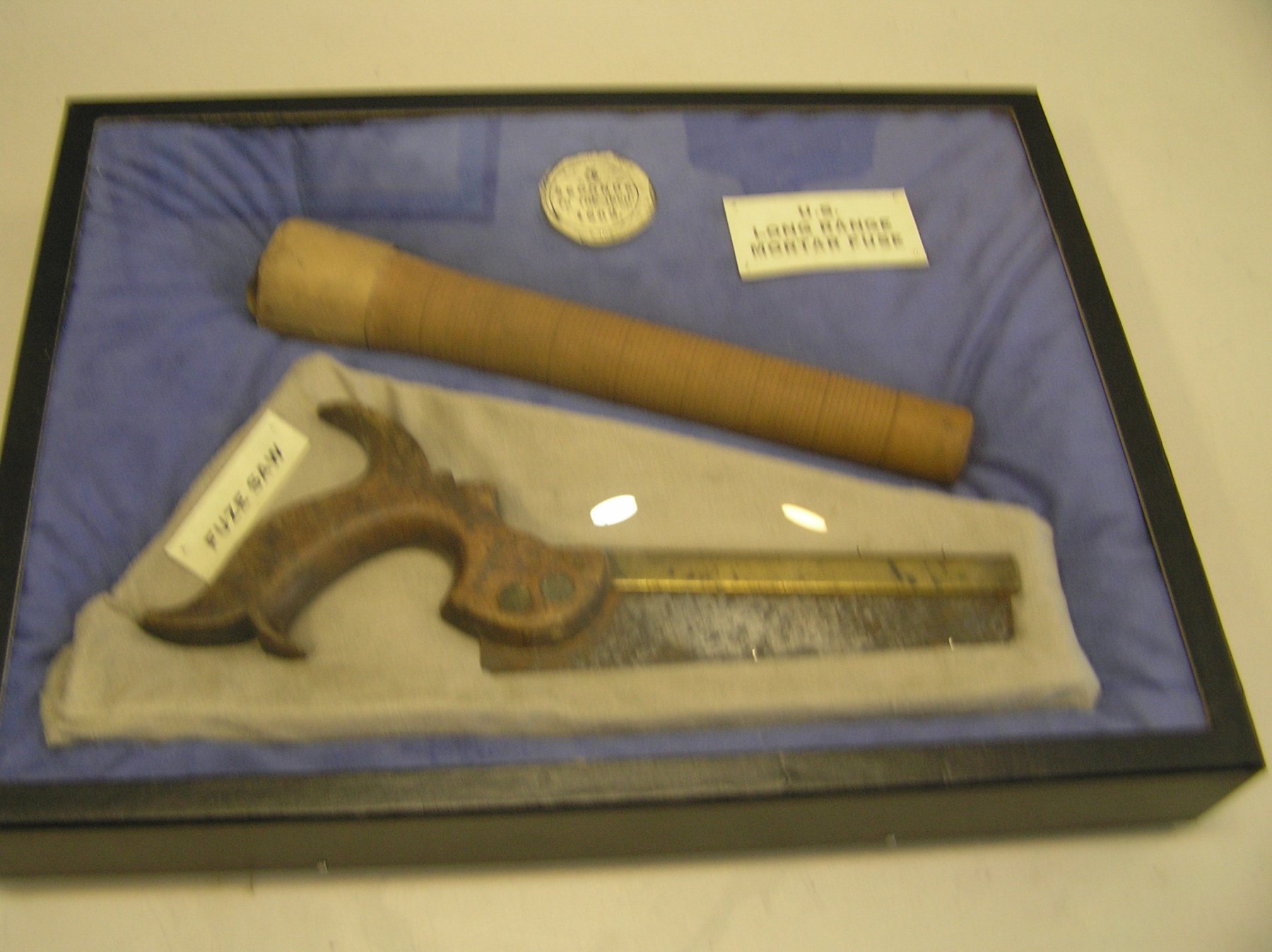
Today in our meeting our Civil War buff introduced us to his next model, a Civil War Mortar Schooner. The vessel he is considering is the CP Williams that housed a single mortar mid deck. In that discussion our host of the Military History Society of Rochester NY introduced us to a fusing "stick" that he related was used as a timed fuse for the actual projectile. In the picture below (sorry for the fuzzy picture) one can clearly see the shaft demarcations representing some time interval. As related, the saw was used to cut the shaft to achieve the burn interval desired. Then this all gets a bit fuzzy for me. Can someone shed further info on exactly how these were used i.e was the ball loaded with gun powder, how did they judge the correct time interval, was the fuse lit by the explosive force of the charge etc.? Secondly all 20 of these vessels were re-purposed schooners and as such there are no drawings in the National Archive. Does anyone have a source of further info on these schooners? Judging from the mass of the mortar certainly some rework of the vessel's backbone had to be considered. Thanks Joe

-
neillydone: If I understand you correctly all bulkheads are not glued in. If so it should be relatively straight forward to inscribe the bearding line in the stern area. In your photo the lowest "reach" of each bulkhead should be marked. Remove all bulkheads and pencil in a "fair" bearding line as right now it doesn't look so. At this point with the bulkheads removed I would check them with the drawings (a body plan or bulkhead pattern) to see if those in that area correspond. If not I would address the discrepancies by adding in/sanding out the bulkheads to make them meet the bearding line as previously " faired" in. Then I would flat chisel out from the bearding line down to the keel, tapering the excavation so you have near a smooth intersection of the double planks and keel, if needed. Its hard to tell by the picture if the keel stands sufficiently proud of the backbone to accomadate the planking. If it does you can skip the prior comment. In regard to the "fillers in the bow area, a near similar approach would seem to suffice. Once again remove the bulkheads and carve back 13 "fair" with the bow curvature to 14. Now it may be that the pull back of 13 will leave too much of a plank landing area aft of the stem. If so I might be tempted to fill the area where 13 and 14 live with balsa or bass and fair them in to leave a better contour aft of the stem. Hope I didn't lead you astray. Just how I might deal with the problem. Joe
- 13 replies
-
- 2
-
-
- rabbet
- bearding line
- (and 4 more)
-
Atlantis by Thistle17 - FINISHED - Robbe
Thistle17 replied to Thistle17's topic in RC Kits & Scratch building
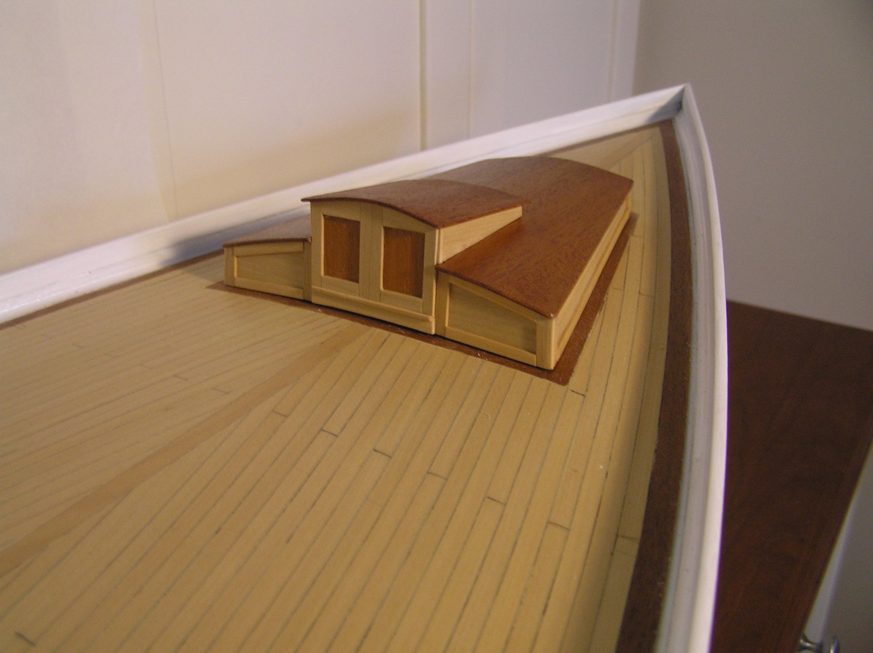
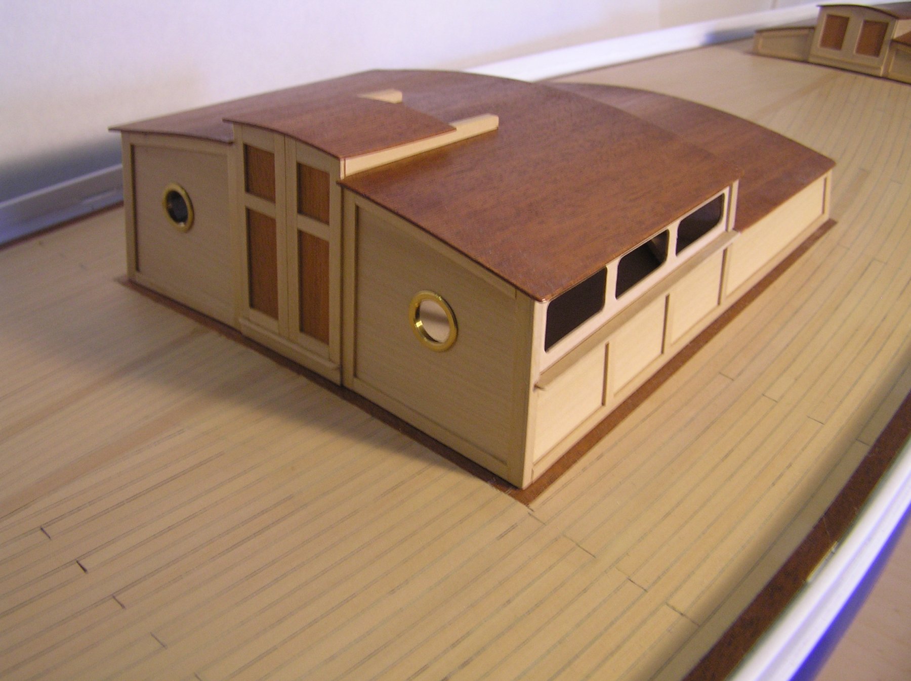
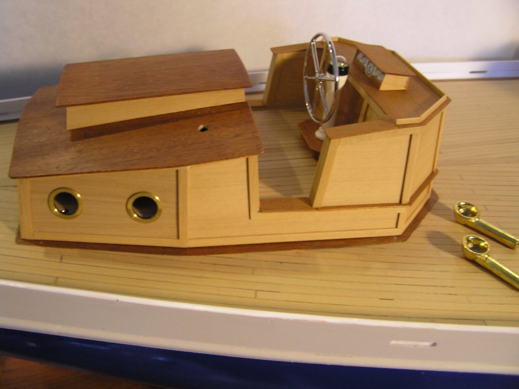
Hard to believe I am finally approaching the end of the deck cabins for Atlantis. They have been mini projects in themselves that never seemed as though there was an end in sight. Fundamentally the deck furniture woodwork is done save the main cabin sky lights and handrails for this and the aft cabin. The body wood is boxwood and the roof and some trim is mahogany. They have been coated with Minwax wiping varnish. The last appointments will be the running lights, air vents and hatch handles. I have not decided how to treat the porthole and cabin "glass" quite yet. I was reading McCaffery's book and he suggests .025 microscope slide glass. Only timidity I have is how do I accurately cut the porthole glass. Secondly the back side has to be opaque as I did not finish the interior of cabins. One final note. I took some stylized liberty with the furniture. Call it aesthetic license or whatever they just looked better to me. Note the "gauges" on the helm (aft cabin). I went on line and found an actual boat panel I liked, then modified it and reduced it to scale. Maybe that is why it has taken me way too long to get to this point!

-
Byrnes Thickness Sander Advice
Thistle17 replied to janet bode's topic in Modeling tools and Workshop Equipment
I would suggest you describe your episode as accurately as possible to Jim Byrnes as it could have been any number of things including the motor itself (faulty field winding, capacitor start circuit), your power source (brown out conditions), loading i.e. rate of feed, how much you tried to remove in a pass. Joe -
I too stumbled into this thread and was amazed at your mastery of wood tools of hand. You are truly gifted and I might add "fearless" to have attempted such a model, at this scale, as your second subject! I believe there are just a few women in this pursuit and gauging your skill level there are but a few that have achieved your level so quickly. Portia Takakjian probably was the most prominent, but she is gone, so keep doing what your doing and continue to grow. Your work has my admiration. Before I sign off let me say this is not about being female or male. I just marvel that you found a passion in this as I believe the rest of us have. Joe
-
Swan class 3D model in progress
Thistle17 replied to dvm27's topic in CAD and 3D Modelling/Drafting Plans with Software
Denis I was looking more closely at earlier images and your rendering is so detailed. Lighting through the gratings and down the companion way, wood grain, shadows its mind boggling. Its no wonder the GPU is staring to struggle. Nonetheless you are an artist of noteworthy talent. You have my admiration.Joe- 141 replies
-
- 6
-
-
- pof swan series
- swan
- (and 1 more)
-
Swan class 3D model in progress
Thistle17 replied to dvm27's topic in CAD and 3D Modelling/Drafting Plans with Software
Your work is itself a work of art. I have seen convincing computer graphic images but your turned the application of the practicum on its head! It would be a joy to watch you work. In one sense its like painting with sand like the Tibetan Buddhist...oh so beautiful, so intricate, so artful, so amazing but so vulnerable. I do hope you have backed up those files. Joe PS what is the platform you are running on i.e. the memory, graphics, speed?- 141 replies
-
- 5
-
-
- pof swan series
- swan
- (and 1 more)
-
Your tools and sponsorship are soooo welcomed. Great to have you with us. You round out a tool domain of highly acclaimed products. Absolutely love my vertical mill and your great support! joe
-
As a past president's wife said..."When they go low we go HIGH!" Always been one of my life's codes. It is obvious it is yours. Joe
-
Miniature Russian carving tools
Thistle17 replied to druxey's topic in Modeling tools and Workshop Equipment
I got this address from druxey Mike. Hi. I should emphasize that these are for experienced miniature carvers. They are, in the small sizes, very delicate tools, easily broken if misused. However, if you are up to it, they will make a superb investment. Michail's contact info: mihail.kirsanov@mail.ru Regarding handles is a matter of prefrerance. For fine work I would prefer the palm handle version for close in work. Go to Woodcraft and handle their miniature palm set for a similar sense of that style. Joe -
Someone gave me a bottle of Hunterline Weathering Mix, Light Grey. It is a wood stain with rubbing alcohol solution so should not be injurious to the wood. I have not used it yet. www.hunterline.com Joe
-
Small desktop mill for modelling
Thistle17 replied to Roks82's topic in Modeling tools and Workshop Equipment
Rok I have no experience with this mill but I did have a Grizzly import about 8 years ago. It was a bench top model which I ended up selling because of its limited use to me at the time (had not returned to ship modeling yet). The one problem I had with it was that it had nylon gears and one of them failed. I bought the replacement gear set and it appeared to be a relatively straight forward repair. So my one word of caution besides accuracy concerns is I would steer away from any machines that have nylon gears if you plan on other besides modeling. I noticed the Micro Mark web site here in the US also sells heavy duty gears for its lathe so maybe that is a standard practice to use the cheaper gears. See https://www.micromark.com/product/7990 Joe -
CA adhesive, which one do you use?
Thistle17 replied to Modeler12's topic in Masting, rigging and sails
Thanks guys. I tend to shy away from CA for wood to wood application but could not clamp the particular element so I resorted to the CA. Yellow glue for me as a rule. I have found the DAP Insta Cure (all purpose) has worked better. You can even remove it to re-position it within the 1st 30 seconds with good adhesive results in the end. They also make a wood only version I have yet to try. Why I didn't reach for that bottle is beyond me as an alternative. Joe -
CA adhesive, which one do you use?
Thistle17 replied to Modeler12's topic in Masting, rigging and sails
This may be a misplaced entry on the topic of CA adhesives. Specifically I am suspect of my CA, namely bsi Insta Cure, Gap Filling, 5-15 sec adhesive. As a matter of expedience I used the CA to glue Castello box wood to Castello box wood. I noticed it wasn't too hard to pry it off after about 5 days of application as I had made a mistake. Now I am concerned about future loose parts over time. The CA glue is about 7 months old and is still very viscous. Its container is immediately sealed even during use. The box wood is silky smooth as it comes from the supplier. Any similar episodes out there and what have you done to combat this problem? Thanks, Joe -
Rusty has shown the "Winne" to our group. It is a beauty and much desired by a number of us. The starter kit, as Cheerful, with accessories makes it a no brainer for me. I am hooked on this method of building a quality model within a reasonable time frame. It is a most desirable way to go for many of us. I will wait patiently. Joe
-
For my vote I would put the Chebacco at #1 but would not be disappointed to see Pegasus take the first place spot. I happen to be very fond of working craft as much as fighting ships. They were the backbone of our early nation's commerce and some still ply our waters. Your Chebacco is truly an interesting double ender craft. Joe
-
Sam, so this is what you are doing these days in your spare time. Would be nice to have you visit the group, when the weather is nicer, and show us the work, in person, on this great project. I know all would like to see you and your work. You could share your experiences with us as I know a number of us are thinking about this project for themselves. Joe
- 47 replies
-
- 3
-
-
- queen anne barge
- Syren Ship Model Company
- (and 1 more)