ccoyle
-
Posts
10,605 -
Joined
-
Last visited
Content Type
Profiles
Forums
Gallery
Events
Everything posted by ccoyle
-
 Congratulations, Dan! She does indeed look great.
 -
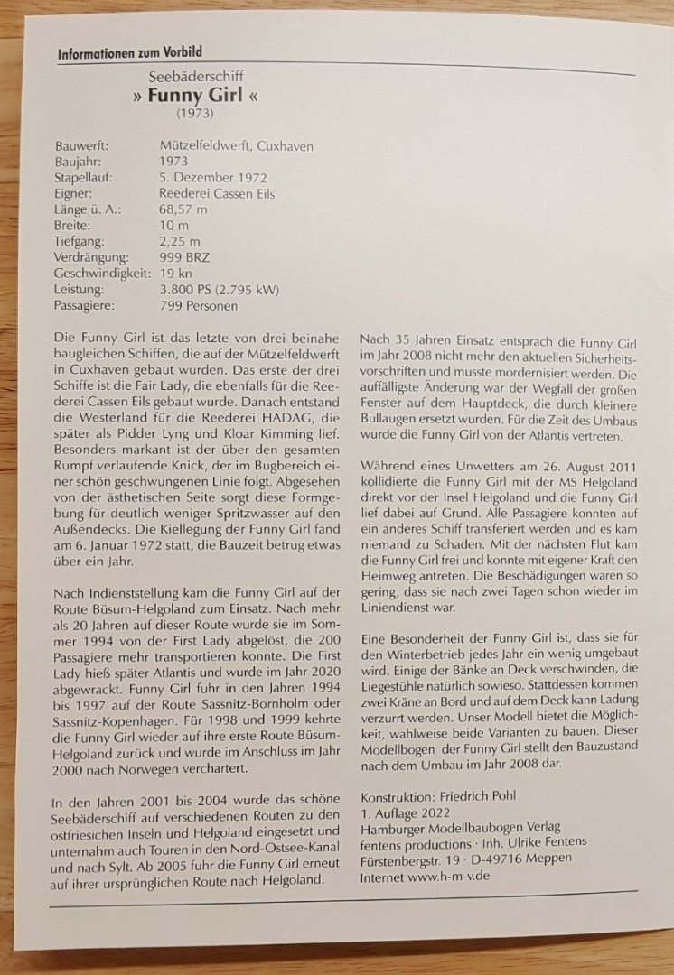
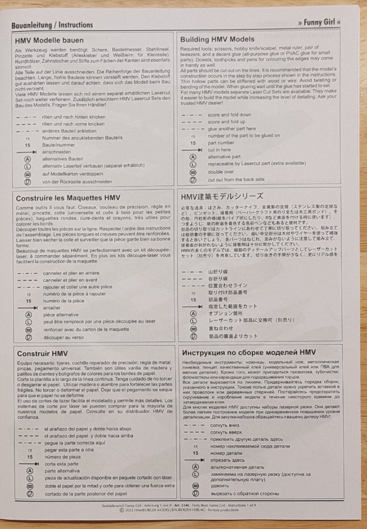
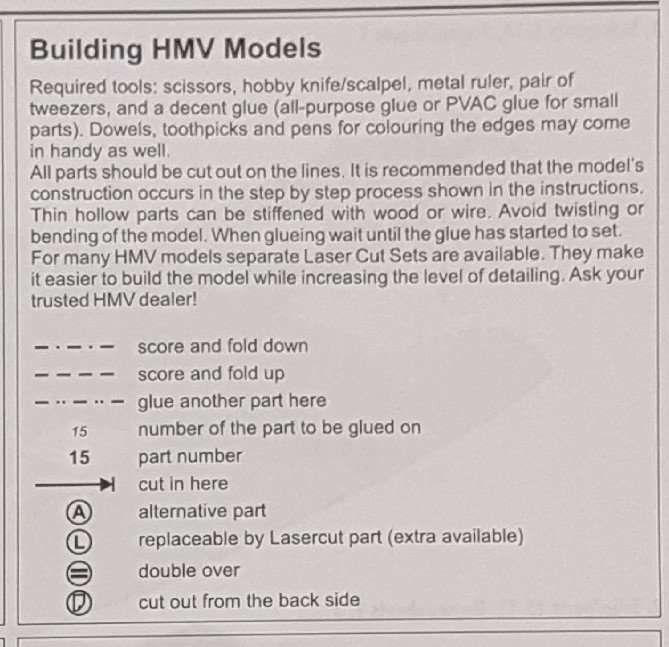
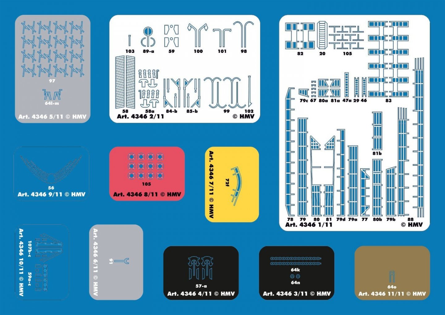
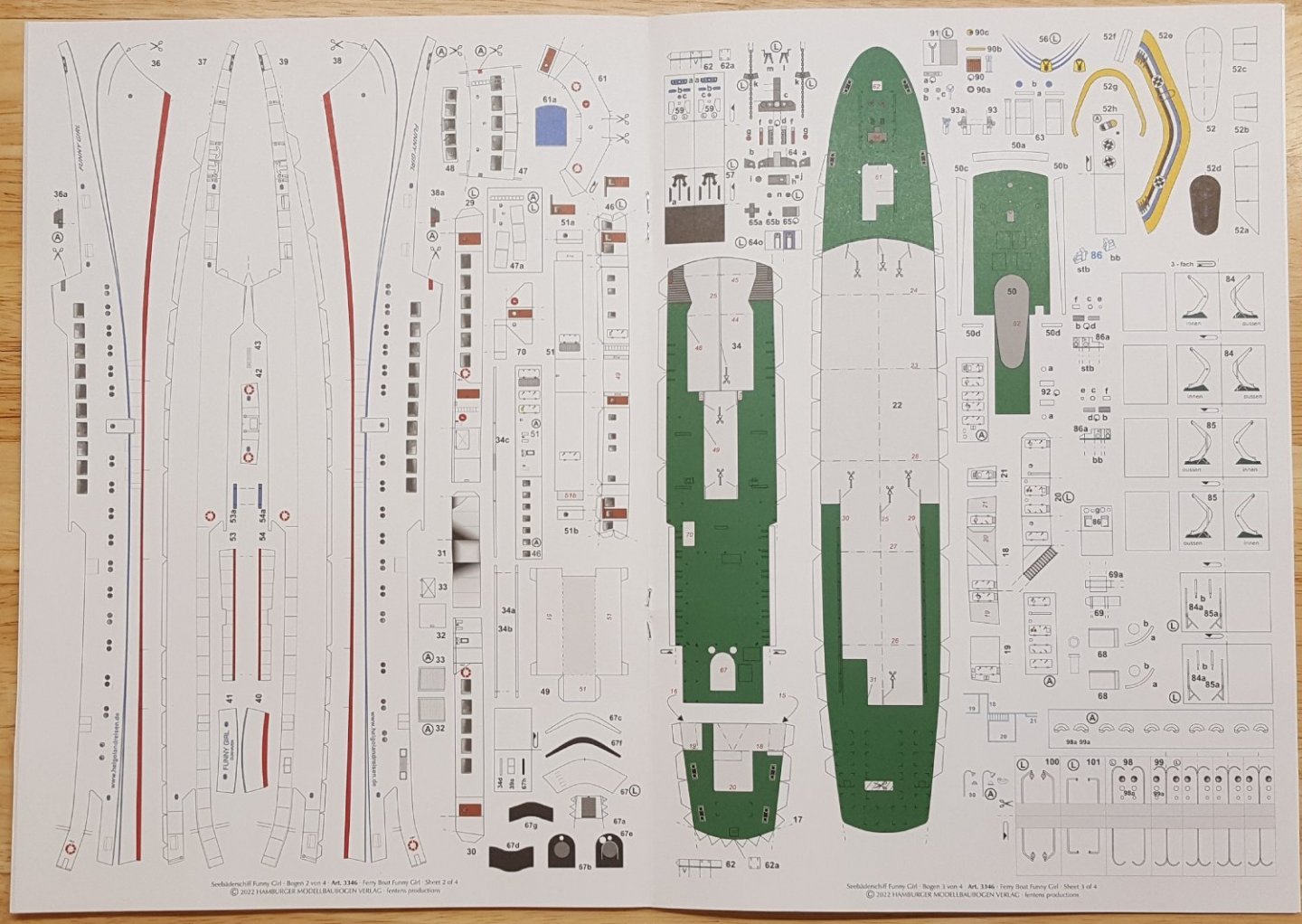
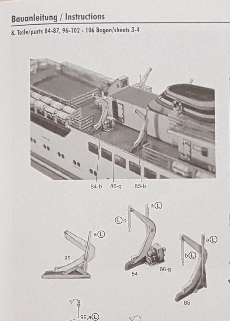
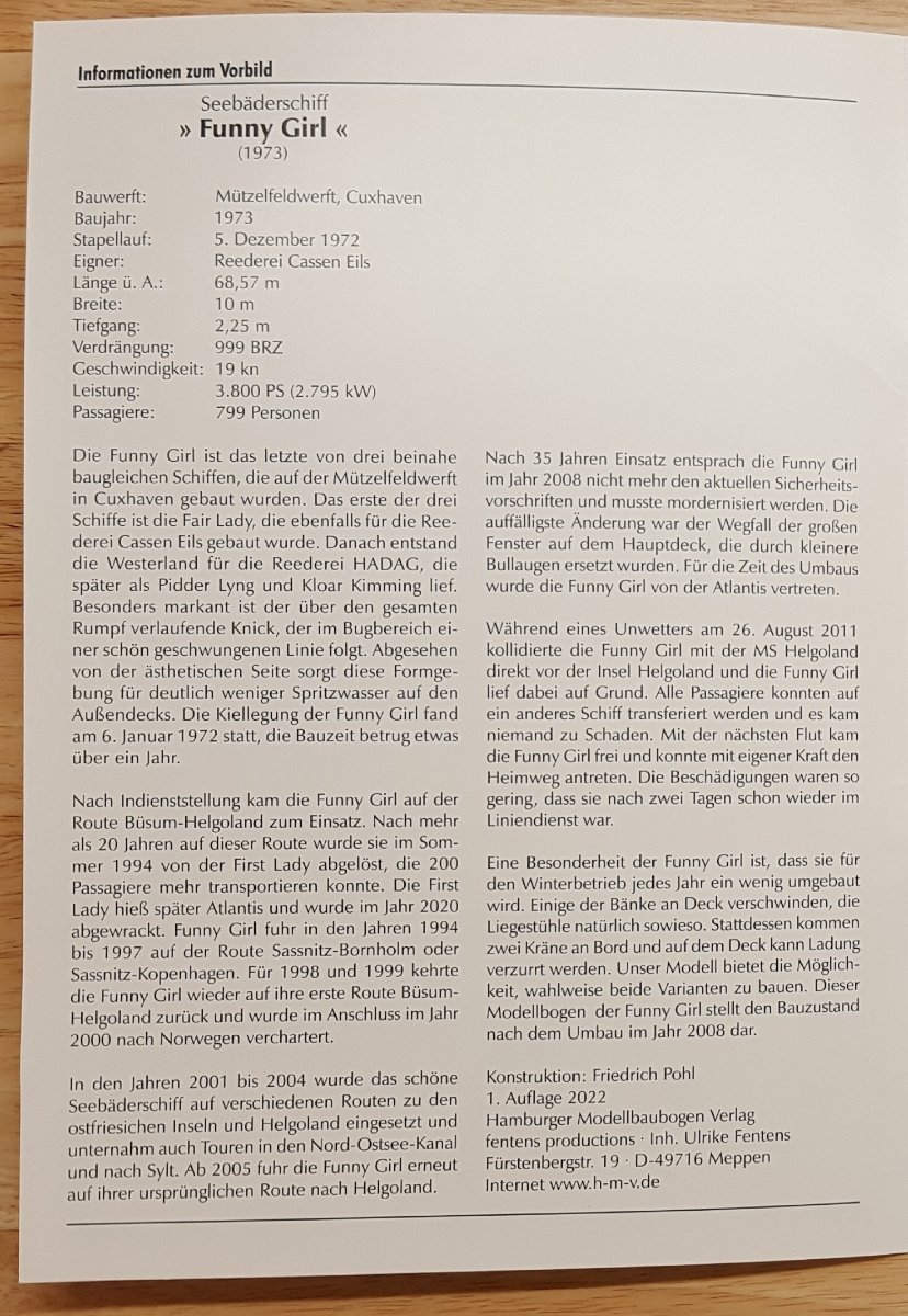
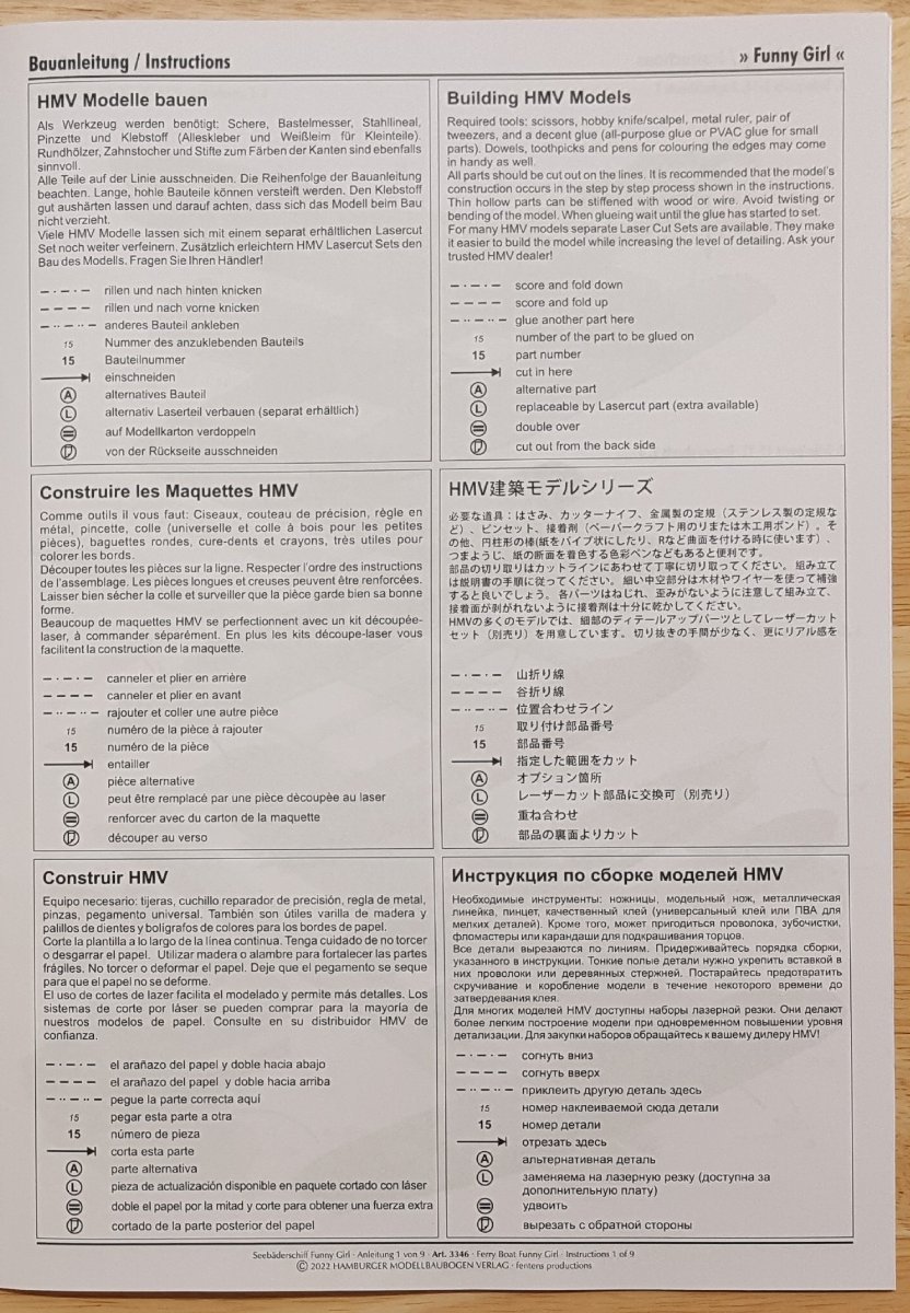
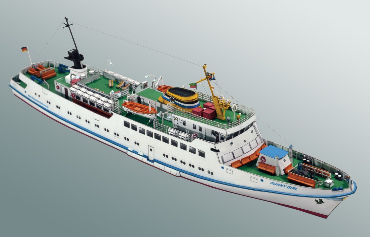
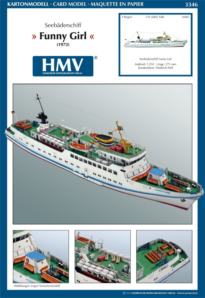
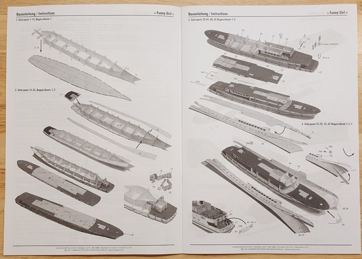
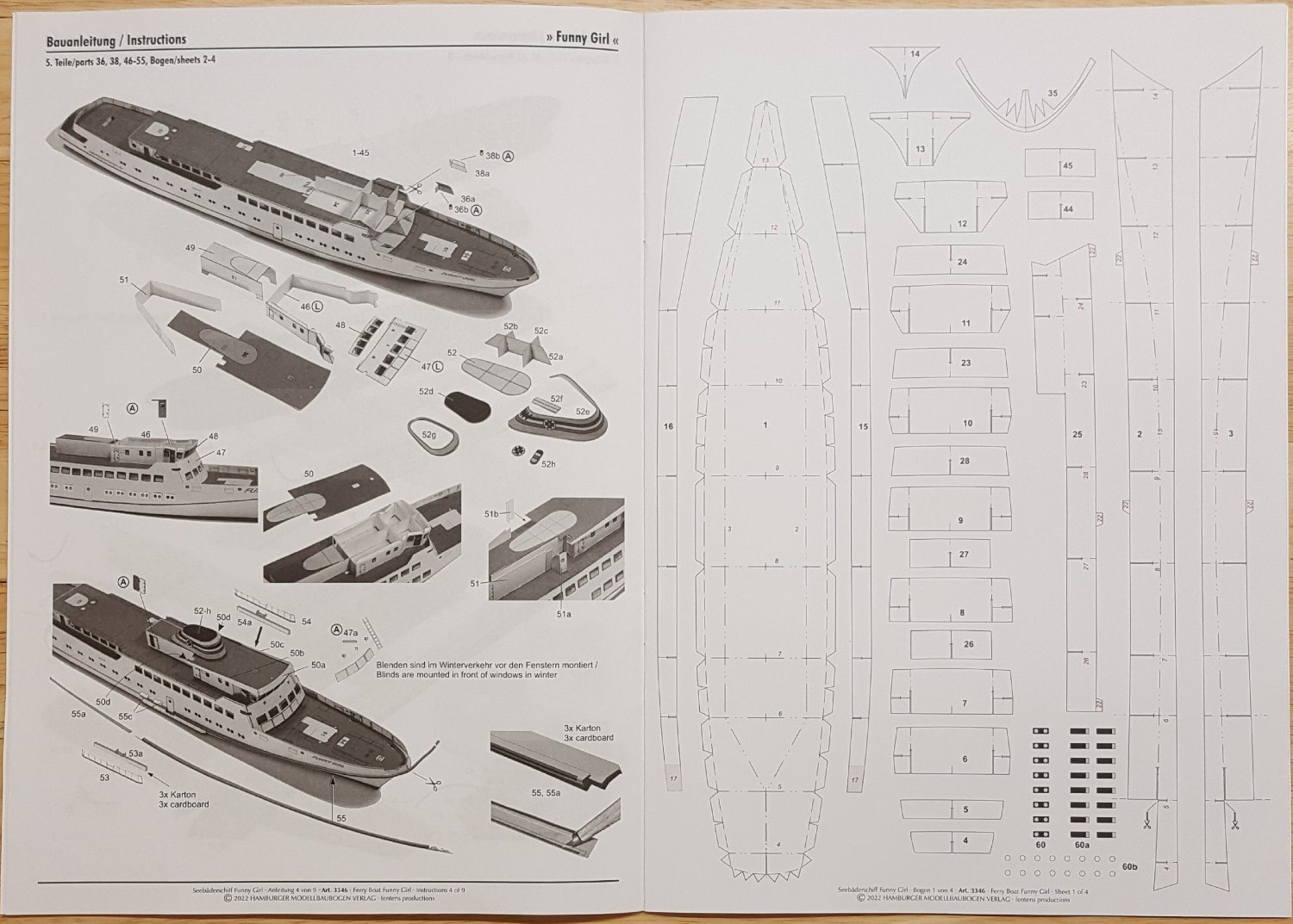
1/250 Seebäderschiff FUNNY GIRL 1973 - HMV Available from Fentens Papermodels €13.99 Photo courtesy of Fentens Papermodels (All photos by the author except where noted.) Hot off the presses in 2022 from Hamburger Modellbaubogen Verlag (HMV) we have another fine addition to their lineup of historical German working vessels. This time, the folks at HMV are offering a Seebäderschiff with the curious name of Funny Girl, no doubt named for either the Barbara Streisand film or for Fanny Brice, the film's central character. The German name for this type of vessel translates as "sea bather ship." This sort of excursion vessel is still used to this day for ferrying vacationing tourists from the German mainland to the various seaside resorts located on that country's barrier islands. Funny Girl was the last of three sister ships (the others being the Kloar Kimming and the Fair Lady) placed in service between 1970 and 1973. Funny Girl remains in service to this day, transporting up to 799 passengers per trip to sunny days on the beaches of Helgoland. As is usual for HMV kits, this design from Friedrich Pohl is in 1/250 scale, producing a finished model that is 27.5 cm in length (10.8 in.). The four sheets of parts contain 534--698 parts, depending on which build options are chosen. The size and parts count have earned this model a rating of 'intermediate' on HMV's scale of 'easy' to 'very difficult.' Upon turning the attractive booklet cover, featuring images of the prototype model, we find a nice description of the real-life Funny Girl. Sadly for many of you, this description is of course in German, which should encourage some of you to learn that fine language. Remember, Deutsch macht spass! These days, HMV kits include brief explanatory remarks on the lines and symbols used in the construction diagrams, so that the builder can know such things as where to make folds either up or down, and where optional laser-cut detail parts may be used. These remarks are written in German, English, French, Japanese, Spanish, and Russian. After tearing my hair out while trying to make sense of the diagrams in a GPM kit, I can tell you honestly that I really appreciate the clarity of the logical HMV construction sequence and diagrams. Experienced card modelers should have no trouble at all in following the six pages of detailed, computer-drafted diagrams. Construction of Funny Girl's hull makes use of the standard HMV 'egg crate' method of construction. Some care and attention to detail is required to pull this off well, so I recommend having one or two simpler models under your built before attempting a larger model like this. It would be a shock to me personally if any HMV kit were not up to the company's high standard of print quality. Funny Girl's printing is sharp, the colors are bright, and the registration is spot-on. Two-sided printing is included on parts that require it. As mentioned earlier, a laser-cut detail set is available for this kit. The circled letter 'L' in a diagram indicates that such a part is available for the item shown. The laser cut set contains eleven frets and includes a complete railing set, bulwark stays, deck chairs, anchor chains, life belts, anchors, and many other fiddly bits that are difficult to cut out from the printed parts sheets. The set costs €13.99. (Photo courtesy of Fentens Papermodels) A nice final touch in the kit is the addition of two pages of B&W photos of the actual Funny Girl. As you can tell for yourself from the kit prototype model, this new HMV offering can be built into a very attractive model -- and it won't take up a lot of shelf real estate when completed. (Photo courtesy of Fentens Papermodels) HMV's Funny Girl will make a wonderful addition to any collection of card models, but will especially appeal to those who have a fondness for small but attractive passenger vessels. Both the Funny Girl kit and its laser-cut detail set can be purchased from the Fentens Papermodels site at the link provided at the top of this review. Be sure to tell them you saw it at Model Ship World! Thanks to Benjamin Fentens for providing the copy of Funny Girl for this review.


.thumb.jpg.f585e876cef28c444f1bbefd431a38f9.jpg)
-
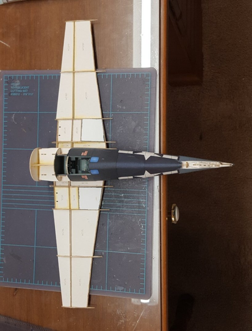
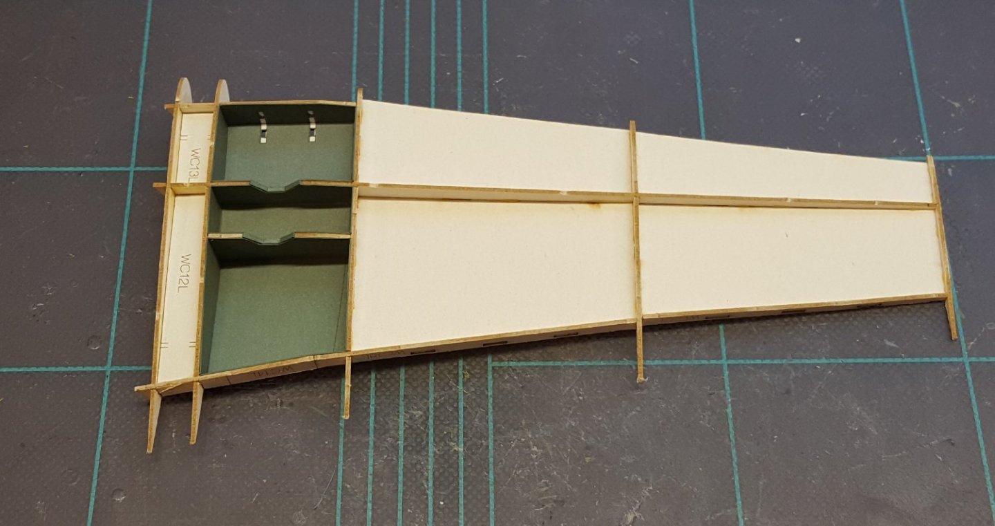
Both wing structures done now. Here they are sitting together with the fuselage --nothing glued together yet, only to give an idea of the size. My cutting mat is about 11" wide, so yeah, compared to what I usually build, it's big!
- 150 replies
-
- 20
-

-

-
Well, Greg, this one should keep you busy for a day or two!
- 203 replies
-
- 6
-
-

-
- Roma
- Micromaster
- (and 4 more)
-
Well, there has been more than the usual amount of excitement in our household this weekend on the non-modeling front. Saturday, the wife hopped into her car to go shopping only to discover that all her car's systems were dead, dead, dead. Happily, the cause turned out to be merely a defective battery, which was still under warranty, so I got a new one at no cost -- easy-peasy. Today, though, I got a call informing me that my daughter had been in an accident. Happily, again, no one was hurt and the damage to both vehicles was minor, but she suffered a flat tire and a damaged rim. Of course, being Memorial Day today, no shops were open, so I can't get her a new rim and tire until at least tomorrow. 😬 Just another of life's speed bumps. 🙄 Okay, back to the 'Cat. In this first image, I have used my talent for 'judicious camera angles' to hide some of the more hideous seams I have made in a long time. I'll lay part of the blame on the kit's design, but part of the blame is on me. Deciding that I needed a break from fuselage work, I put one of the wing structures together. The tabbed construction goes a long way toward making sure that everything aligns correctly; it also make the construction sequence a little iffy to figure out at times, but in the end it all came together, so I'll call that a success. Now on to the other wing -- and hopefully no more car issues!!
- 150 replies
-
- 23
-
-
Ah, I understand now. Pretty impressive so far.
-
Is this a kit of your own design? It looks good so far, but it's certainly not a Caldercraft kit.
-
Wow, Gary! That's another great example of elevating model-making to the realm of art -- well done!
-
Hi, Trevor. First piece of advice is to give your topic a title that accurately represents its content. "SOS!!" is a teaser title that many of our members will simply skip over -- which probably isn't what you want. I have fixed your title for you. I'm not an expert on rigging, but I can bet that our more knowledgeable members will want to know at least three things: What kind of material is your rigging line made of (e.g. linen or polyester)? Did you pre-stretch it? Do you live and/or work in a humid environment? I'm sure someone will be along shortly who can give you some concrete suggestions. Cheers!
-
I've had them for so long, I've quite forgotten where I got them from. They are nothing special -- just a cheap pair of lockable, angled-tip tweezers, probably made in India. You can find them at practically any hobby store, e.g. Hobby Lobby.
-
Agreed! Your vents turned out great. I always find constructing them a bit of an exercise in terror and frustration.
- 23 replies
-
- 1
-
-
- card
- World of Paperships
- (and 2 more)
-
I really like the color schemes used by all of the combatants in North Africa. I have Hans-Joachim Marseille's Bf-109F-4 and a USAAF Spitfire Vb tropical in my card model stash.
-
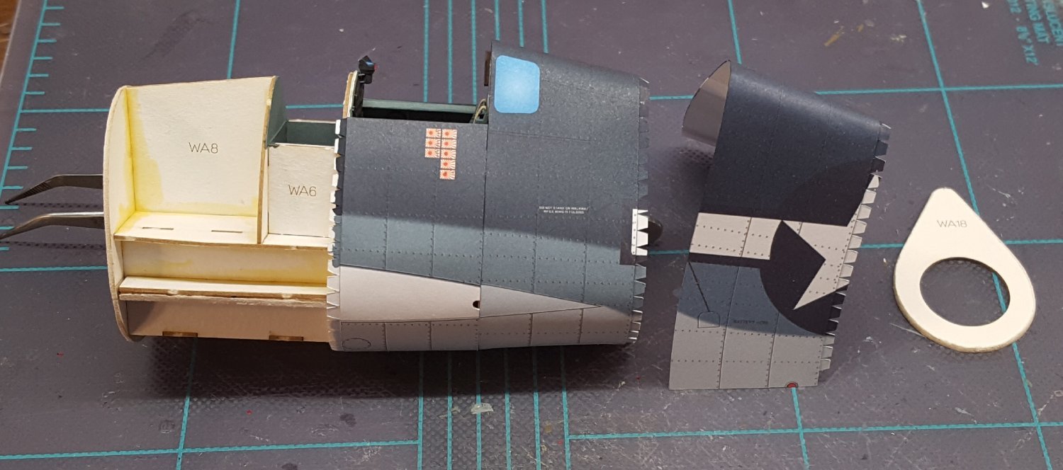
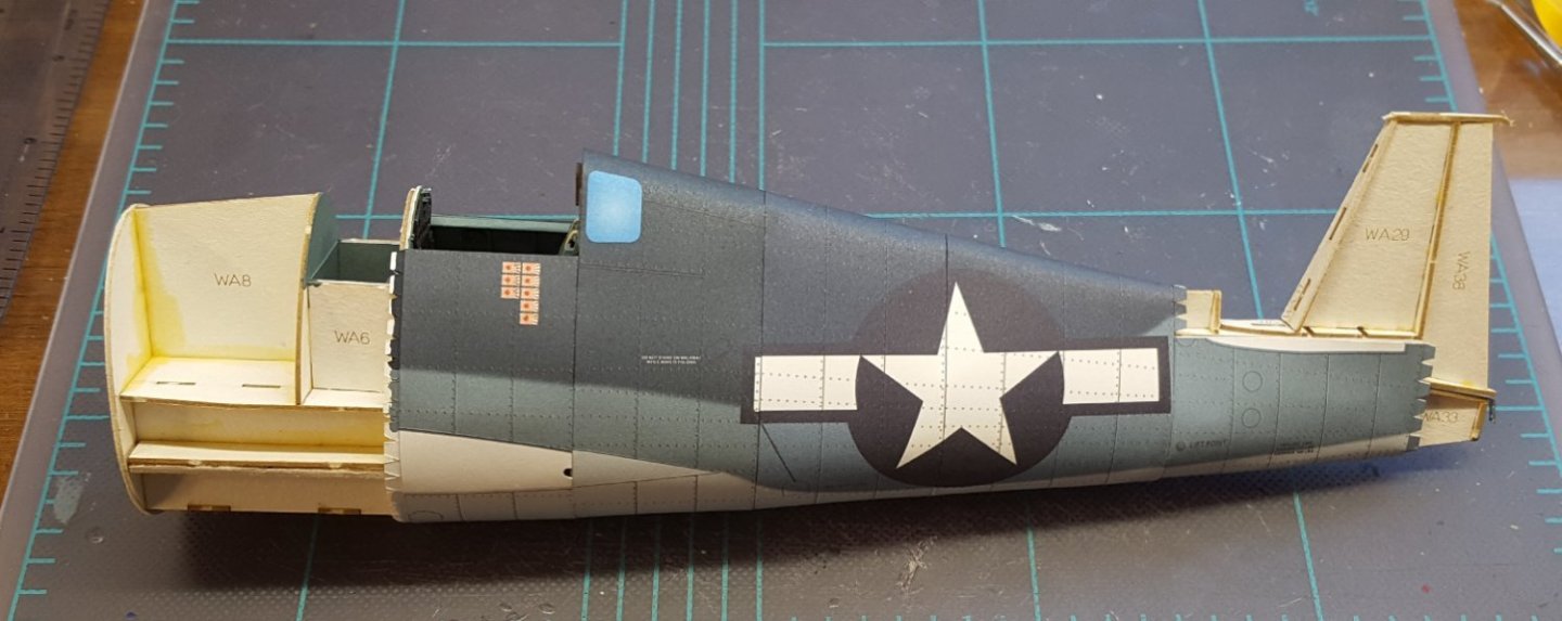
Several things to take note of in this photo: I decided not to glaze the windows behind the cockpit. There's nothing of interest to see in the compartment, and cutting out the printed "glass" panels would leave a very narrow and weak strip right next to where the sharpest bend in the exterior skin is -- that's a potentially deadly combination. Plus, the skin fit is very tight, and adding the glazing would make the fit worse. There's a slight alignment error, which you can spot at the place where the wing's trailing edge will eventually meet the fuselage. There was little to nothing I could do about this -- the dorsal and ventral alignment tick marks matched perfectly. The opposite side matches perfectly, too, so correcting this side would only throw off the other side. Oh, well. Worse than the slight alignment error is the fact that the colors on the next fuselage section, cut from a different parts sheet, don't match those on the previous section. You can see the difference in the photo -- it's not a trick of the lighting, and it's more apparent in real life. The blue on the forward section has a definite greenish tint, while the aft section is a truer blue. Since some of the fuselage skins are printed on one sheet, while the rest are on the second sheet, this mismatch will be seen elsewhere on the fuselage. It's kind of a bummer, and it's a printing error, so there's really nothing to be done about it. Cheers!

- 150 replies
-
- 21
-
-

-
Coming into ship modelling from a unusual angle
ccoyle replied to von_bednar's topic in New member Introductions
Witam! Sounds like a scratch project to me. As one of our forums die-hard card modelers, I have a great appreciation for Poland's contributions to the art of modele kartonowe. Enjoy your stay!- 14 replies
-
- 10
-
-
Constructo used to make a kit for it. It might turn upon eBay.
-
If anyone is interested in this kit, Model Expo currently has it on sale for $69.99, which is a good price.
-
Bravo, Andrew!
-
BTW, if anyone is still thinking about trying a card model, this estate sale over at Paper Modelers still has a lot of models left to choose from. Personally, I'm trying very hard not to make a third purchase from this sale, because I already have enough kits to last me a lifetime. 😬
- 150 replies
-
- 11
-
-
-
Kit Review Harbor Tug WARATAH 1902 - HMV - 1/250 - CARD
ccoyle replied to ccoyle's topic in REVIEWS: Model kits
I'm not clear on what you are asking for. Did you order the laser-cut detail set but not the actual kit itself? Because the instructions come with the kit. -
Very striking! I enjoyed the sequence of photos showing the yard being hoisted. Cheers!
- 59 replies
-
- 1
-

-
- Billing Boats
- Le Martegaou
- (and 1 more)


.jpg.400dfd944f133ba3079d0ab8c5730bc2.jpg)