ccoyle
-
Posts
10,590 -
Joined
-
Last visited
Content Type
Profiles
Forums
Gallery
Events
Everything posted by ccoyle
-

Russian T-62A Tank by CDW - Tamiya - 1/35 Scale FINISHED
ccoyle replied to CDW's topic in Non-ship/categorised builds
Does it come with uncompartmentalized ammo storage racks inside the turret? -
Looks great!
-
And the bidding starts at only 500,000 GBP. No, thanks -- too rich for my wallet!
-
USF Essex by mtbediz - FINISHED - 1:50
ccoyle replied to mtbediz's topic in - Build logs for subjects built 1801 - 1850
That is a very handsome model, Mustafa, and one to be proud of. Congratulations! -
Shave, shape -- makes no difference. Correcting that one word won't hide the fact that the instructions are practically worthless. Last night I distracted myself by doing a little painting of the resin wheels -- pictures later. How much later has not yet been determined!
-
This is why you need to have a maritime gallery assess it, not a random model builder. The price range can vary considerably depending on the type of model, age, and condition. What you need to do is take a good set of photos and then Google search for "maritime art gallery"; one or more of them may be able to give you a preliminary assessment based on your photos, but to firm it up they would probably want to lay eyes on it. Tell them you have a ship shadow box diorama.
-
So, I am now ready to start on the main landing gear, and this I can tell is going to be really, really fun. 😧 First, there is a ton of parts, including many tiny ones. Second, these parts are scattered across the parts sheets instead of being in one place together. Third, the bay doors have a curved surface in them, and just the main doors alone -- sans all of the strut attachment points, consist of five parts each; the curved parts are supposed to go in an area cryptically marked "cut out after forming" -- and I'm, like, "Dudes -- I can't see how the curved parts are supposed to fit unless I cut that portion out first." The instructions do not help on this point at all. I translated them into English, and this is what I got: "Refer to the assembly drawings to make the chassis shave. Particular attention should be paid to the precise and solid construction of the G12-G15 chassis leg suspension." That is the sole instruction on how to put the main gear struts together. Beats me what a "chassis shave" is. 🤔 The diagrams shed very little additional light on the assembly process. Pray for strength!!
- 150 replies
-
- 11
-

-
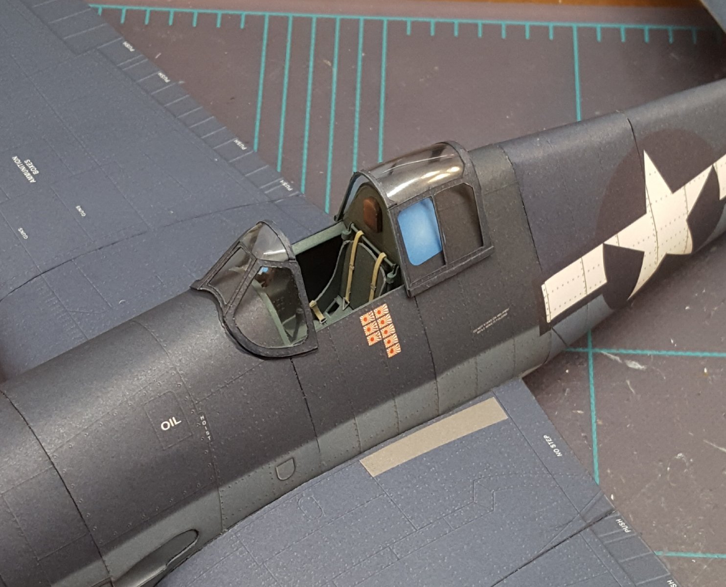
Some cardists do this to good effect, but I'm far too lazy, especially when an after-market canopy only costs a few dollars.
-
Models in any medium are welcome here. Enjoy your stay!
-
"canopy" = the clear, vacuformed after-market product "frames" the printed canopy + windscreen framing from the kit
-
Hi, Shane. First word of advice is don't do anything to this model until you have had a knowledgeable maritime art dealer assess it. These things can have some collector's value depending on their age and provenance, and the patina of age may even be a desirable characteristic. The subject appears to be a bit fanciful. The ship has the masts and secondary battery of a pre-Dreadnought, but the American Civil War had demonstrated the superiority of turret-mounted main batteries, and casemate-mounted main guns were largely a thing of the past by the mid-1870s. AFAIK, all British pre-Dreadnoughts carried their main armament in turrets. Have fun unraveling this mystery!
-
It turns out I overreacted a bit to the molded canopy issue -- it is apparently formed slightly over-sized on purpose. By gluing the framing to the portion of the canopy that it actually fit instead of presuming it should have followed the molded "edge" areas, everything works out. Of course, by not being able to follow the "edge" areas of the molded canopy, some guesswork is involved on where exactly to glue the frames in relation to the canopy's curvature, but that worked out, too.
- 150 replies
-
- 12
-
-
Welcome aboard!
-
Welcome aboard, Rob!
-
What?? 'NMM' was a perfectly serviceable acronym. Now I have to unlearn that one and memorize a different one. 😜
- 488 replies
-
- 8
-
-

-
- Indefatigable
- Vanguard Models
- (and 1 more)
-
Hi, Gizmo! I had a look at your uncle's models and posted a comment there. Thanks for sharing!
-
Welcome, Dennis! I'm not an RC guy, so I can't help you on that front, but hopefully some of the guys who dabble in that niche will come forward to answer your questions. Cheers!
-
Welcome aboard! My dad did the same, but for B-47s in the USAF. I commend you for getting back to your project after a 37-year layoff -- have fun completing it!
-
Remember the not-very-realistic propeller hub in this kit? Here's what the one in the Card Army F4F kit looks like: Of course, the Wildcat in the photo is being built by a real modeler, not me. The Card Army kit is like a six on a difficulty scale of one to five.
- 150 replies
-
- 14
-
-
-
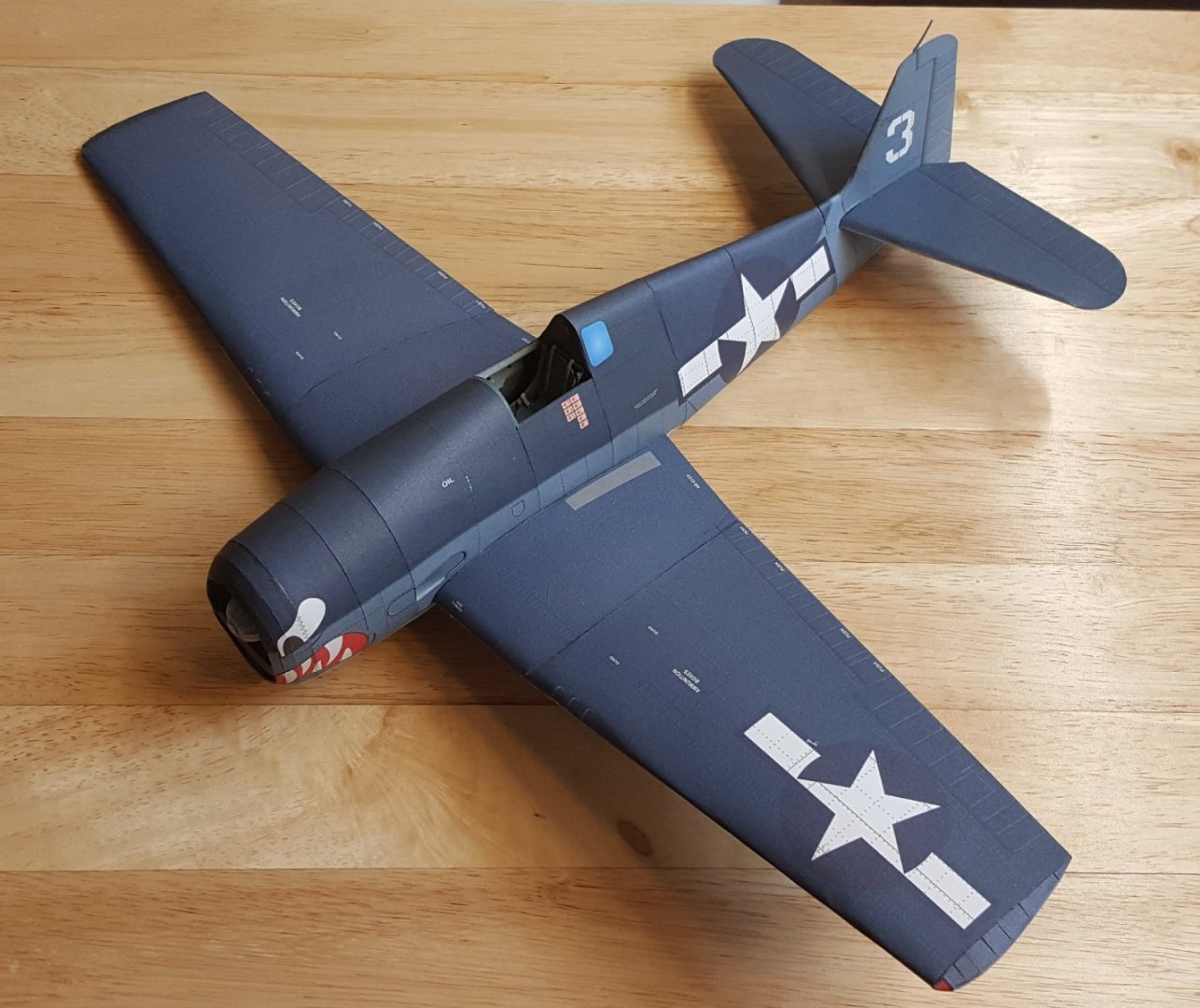
Quick update -- wings and stabilizers attached to fuselage. I'm still impressed by the aircraft's sheer size. The model is a bit over 11 in. in length and has an almost 16 in. wingspan. I couldn't clear away enough clutter off my workbench to make room for this shot, so I had to move the 'Cat to a different table.
- 150 replies
-
- 17
-
-
Condolences to all of your family, Mario, and congratulations on completion of your fine model.