KeithAug
-
Posts
3,986 -
Joined
-
Last visited
Content Type
Profiles
Forums
Gallery
Events
Everything posted by KeithAug
-
 Thank you all for your continued interest and comments and if I make you laugh that is a bonus. I would struggle to make paint drying very interesting so my posts may be a bit less frequent. As expected the first coat didn't dry and was still much too tacky to do anything with this morning. The hull is now in the boiler room - hopefully a little heat will help. Jeff, it is easy to forget that I sometimes do things not everyone is familiar with. I think I should explain myself a bit more. I picked up the technique of wipe on poly some time ago from another build on MSW. I use clear polyurethane either matt or silk finish. I avoid the gloss stuff because to me it looks quite unrealistic at small scale. You can buy wipe on poly but it is basically only normal poly diluted so I just buy the normal stuff and dilute it myself, usually 1 part poly 1 part white spirit. I apply it by taking some wadding and wrapping it in a lint free cloth and then wrapping an elastic band round the neck to hold the wading in place. I always wipe the poly on in thin coats to avoid the potential for runs and always finish the wiping process in the direction of the grain. After each coat I buff back the surface with wire wool. It usually takes 4 or 5 coats before the wood is sealed and an even sheen begins to appear. If I do mess up and get a run I sand this back locally with wet and dry paper. By 10 or so coats I am finding it difficult to see any improvement with each coat so I stop.
 -
Eberhard - the paint can does not quote a temperature and to be fair it says dry to the touch in 4 hours - repaint 16 to 24 hours. If it does not dry overnight I will move it into the boiler room. I start getting reluctant to go into the workshop when the thermometer reaches about 8 deg and below that I take a fan heater with me, by 12 deg I am comfortable enough not to notice the temperature. I suppose we are all comfortable in what you are used to, a certain Canadian gentleman tells me he only thinks about changing out of his T shirt and shorts once the temperature gets down to a couple of degrees.
-
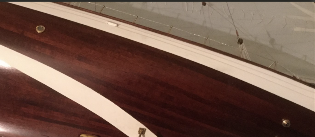
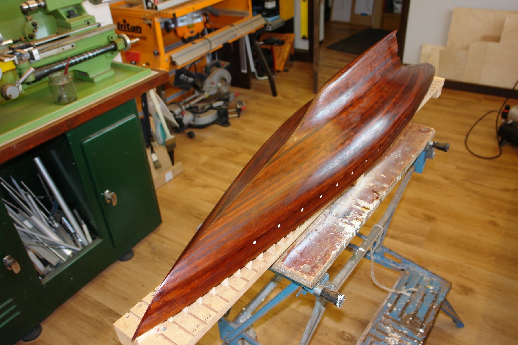
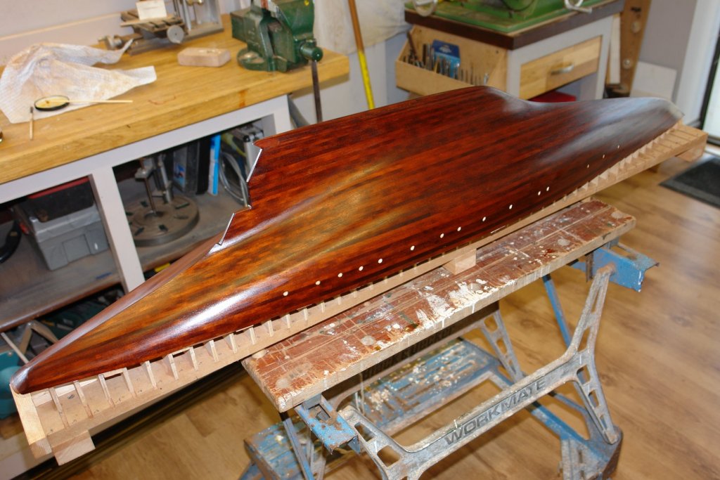
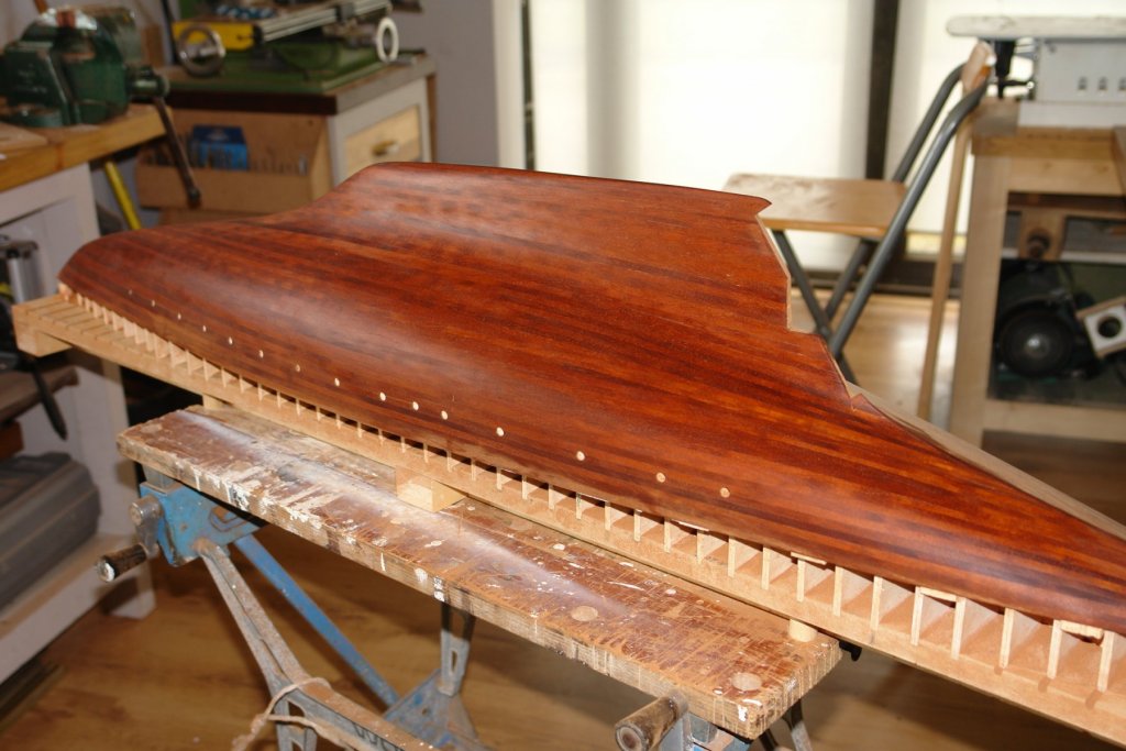
Today I applied the first coat of wipe on polyurethane and took a couple of shots while still wet. In the past I have had trouble with the first few coats drying. Not sure why but I find the poly is tacky to the touch well beyond its stated 4 hours drying time. The workshop toady was sitting comfortably at 12 centigrade and humidity was low, never the less 8 hours after application and the hull is still much too tacky to contemplate another coat. I'll leave it overnight and see how it is in the morning. I am expecting to have to apply upward of 10 coats so progress on the hull is going to slow and I am going to have to find something else to do - either deck fittings or sorting out the garden. I am hoping for rain!!!! I am reading with interest the postings on painting recommendations but I think I had better narrow down the debate. Below the water line Germainia is painted a rather unattractive black. Above the waterline is white with the exception of decoration which is in gold. Some time ago I made the decision to finish the hull below the waterline with clear polyurethane. I know this won't be consistent with the steel hull but its the penalty I have to pay to get it on display in the inhabited area of the house. My original plan was to paint above the waterline white with the decoration in gold - as per the original. However a number of comments posted here and from daughter have raised doubts. I have to remember that my daughter plans to house my efforts when she consigns me to a care home. Apparently doing what she wants earns me points which I can trade in for a better quality home when the time comes. I feel I have to paint a waterline band in white whatever happens so this decision is made. The only question really outstanding is whether I repeat the same paintwork scheme I used on Altair or stick with my original plan to paint above the waterline white. Thank you Keith, Pat and John for your comments and thank you to everyone else who has visited.

-
Wonderful work, really exceptional - and i do like the radiator in the workshop, must get one soon.
- 589 replies
-
- 2
-

-
- le gros ventre
- cargo
- (and 1 more)
-
As always it is a pleasure to find your updates Dan. I just get a bit depressed when I see how much you have achieved. She continues to look very smart. Looking forward to the next update.
- 238 replies
-
- 4
-
-
- leviathan
- troop ship
- (and 2 more)
-
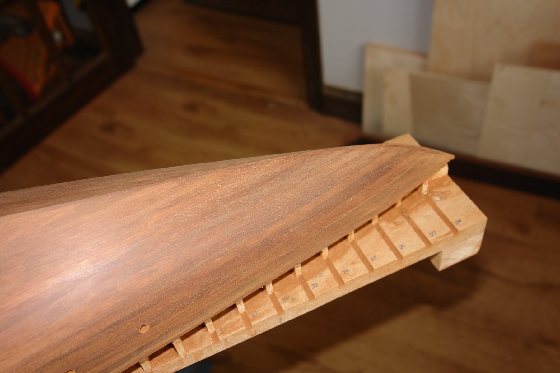
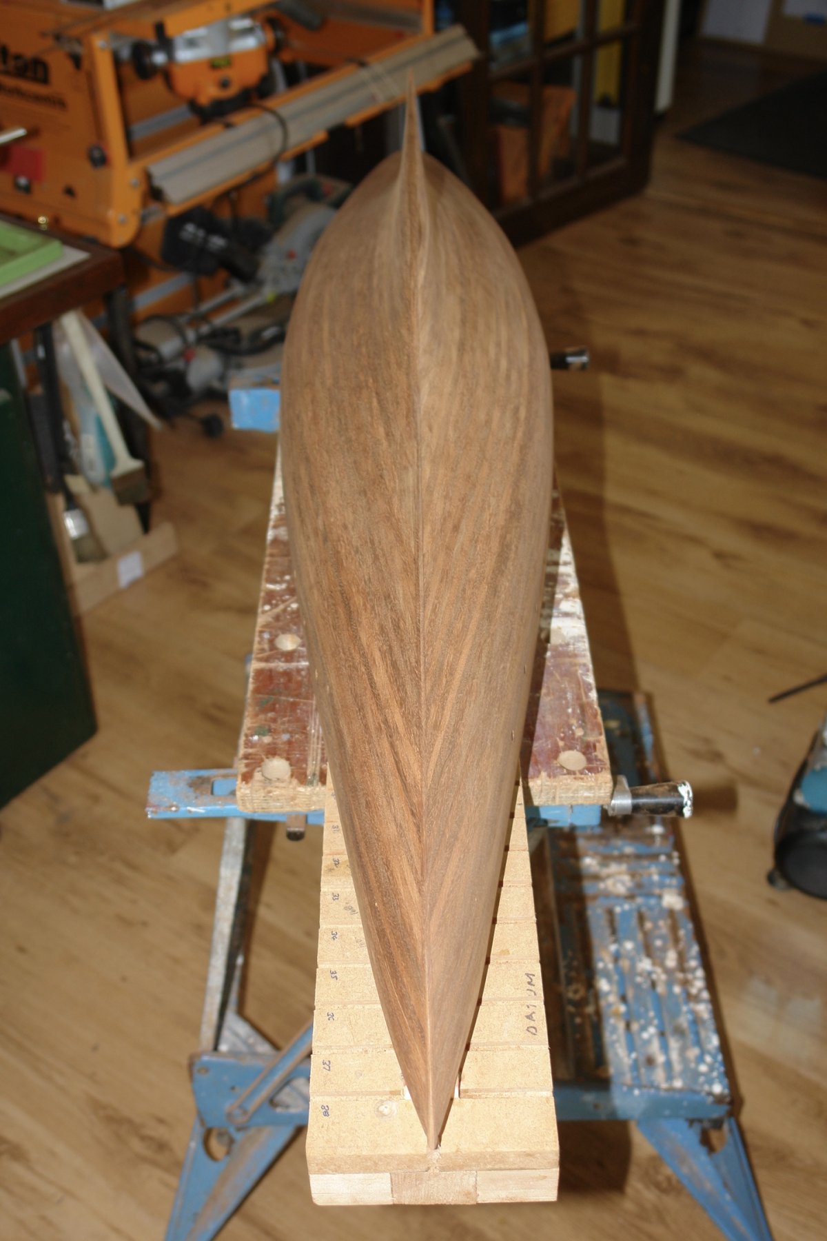
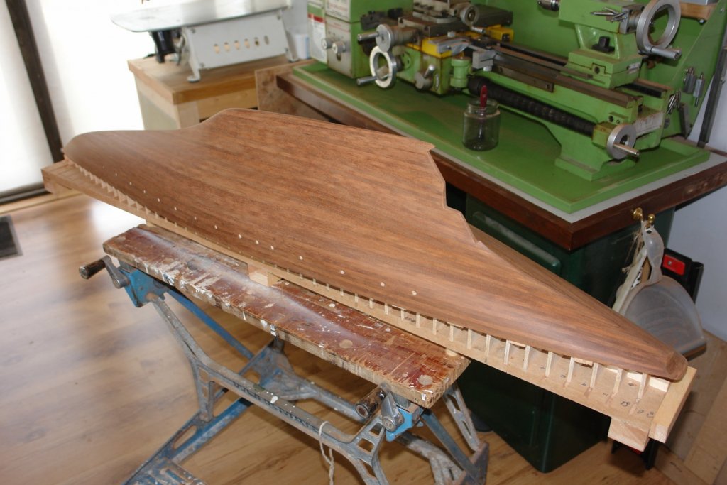
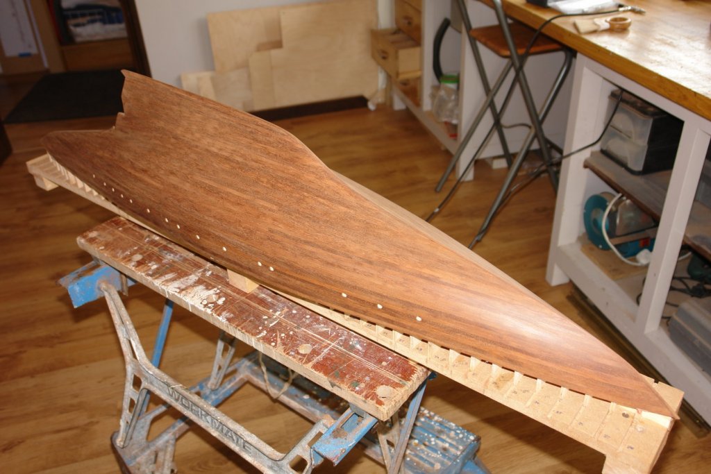
Planker's Progress 13 - Day 27 And so planking (as all good things) must end. I finished the rough sanding with 60 grit paper before spending a couple of hours with 120 grit. I then wet the hull with water to lift the nap. Once dry I moved on to 180 grit paper and repeated the wetting and sanding process twice more. I then moved on to wire wool for a final buffing before varnishing.


-
Mark - it makes sense to me. The Bondo and the responsible crew member permanently part company.
-
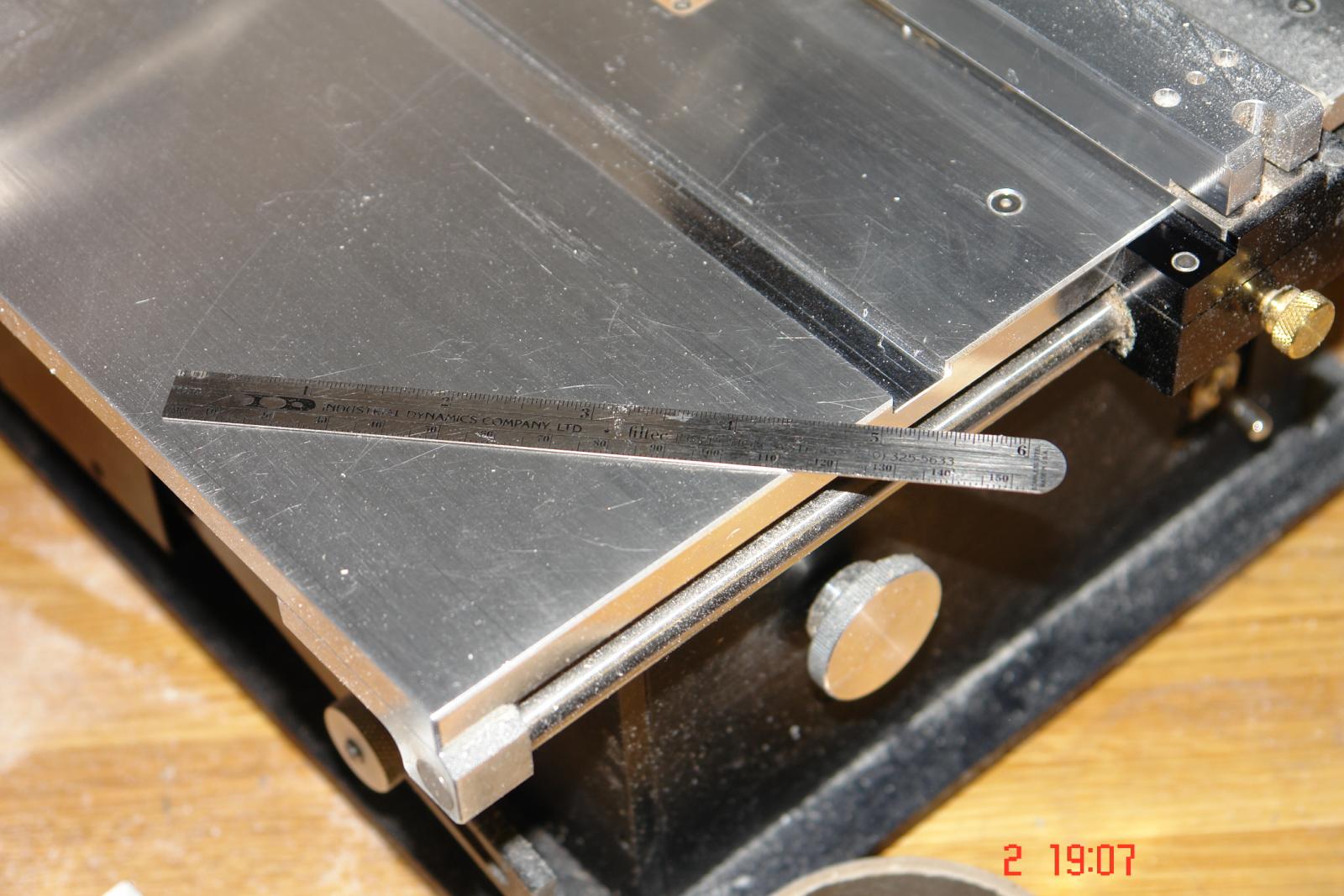
Hi Bob Yes I am aware that this is common practice. Re-setting the fence for each cut is however is a bind when you are ripping a 100 plus planks. Repeatability of thickness is also somewhat of an issue when you are trying to cut to +/- .001" which is typically what I aim for. You are right about the potential for kick back but the use of a sacrificial push stick to push the plank beyond the end of the rule attached to the fence mitigates this problem. The kick back issue is why I only have the rule overlapping the front of the blade by 1/4" once the plank has passed the end of the rule it has clearance and is no longer trapped. I also wouldn't recommend cutting between the blade and the fence if I was working without an attached rule or using anything other than a slitting saw blade.
-
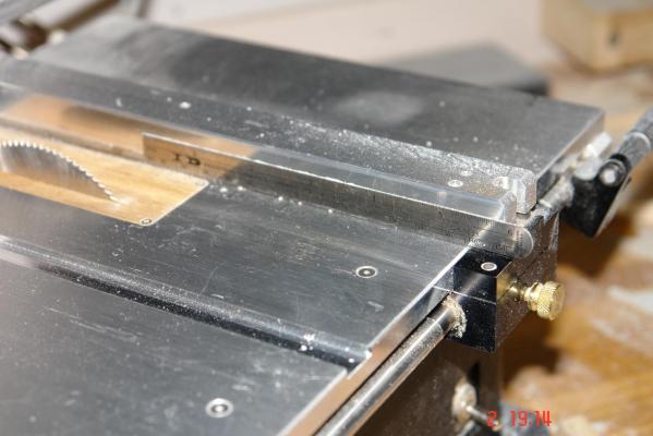
Further to my previous post It is probably worth adding that I cut planks between the blade and the extended (extra height fence), and that i find the following modification very beneficial / necessary:- I tend to find the slight taper on the back of the fence is insufficient when I am cutting thin planks. I know that some recommend locking the front of the fence and then pushing over the rear to increase the clearance. I prefer not to strain the fence. What I use is a .020 thick 6 inch rule which I attach to the fence using double sided tape. The inner end of the rule is positioned 1/4 inch behind the front of the blade. It works a treat.

- 20 replies
-
- 10
-
-
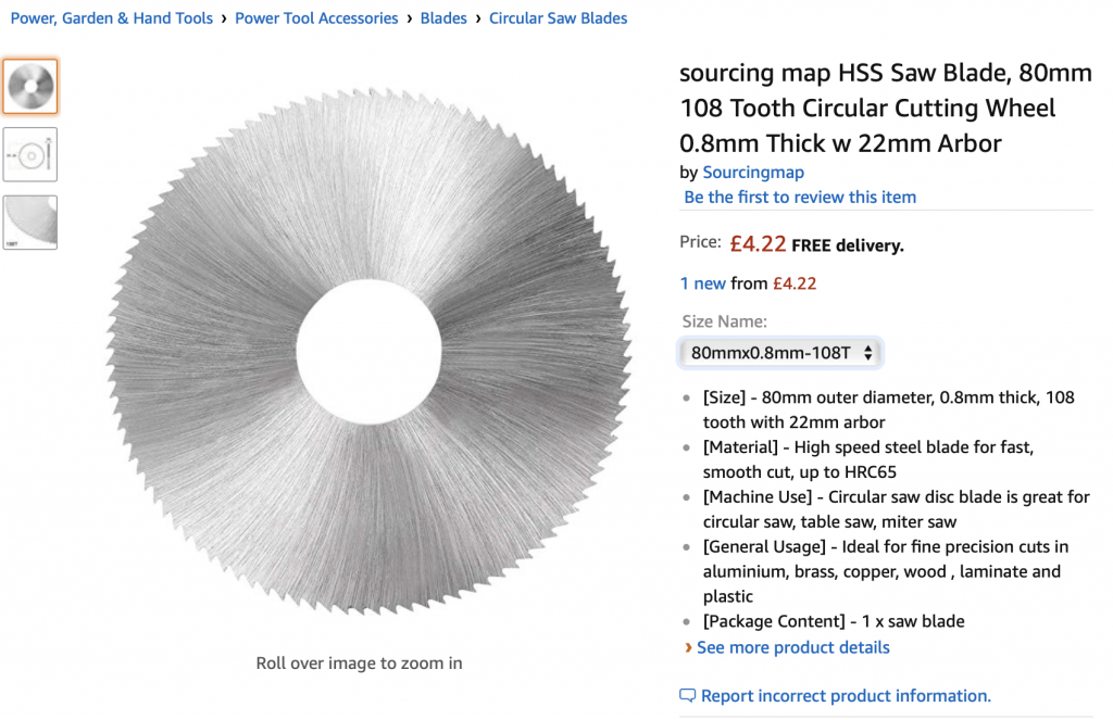
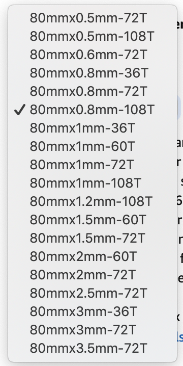
I have done a lot of plank making with the Byrnes saw - mostly in mahogany and obechi. For ripping less than 1/4" stock I always use slitting saw blades. I have only ever had a problem with slitting saw blades when they are dull. For ripping planks anywhere between .020" and .080" thick I use a .0315" thick (.8mm) slitting saw blade of 80mm diameter and 108 teeth. I have tried narrower blades but they flex and produce inconsistent plank widths. For stock that is more than 1/4" thick I use blades of the same thickness and diameter but with either 72 or 36 teeth. Now for a bit of heresy. I use cheap (really cheap) slitting blades off Amazon and sling them when they become dull - which only really happens when I abuse them by cutting metal with them on the mill. Here are the blades I buy. They come in the flowing sizes. Because the blades have a 22mm bore you do need a 1/2" to 22mm spacer. I made one but you can buy them directly from Jim Byrnes.
-
HMCSS Victoria 1855 by BANYAN - 1:72
KeithAug replied to BANYAN's topic in - Build logs for subjects built 1851 - 1900
Pat - I'd be inclined to try Carl's method. Rather than using wire though the holes I'd use a steel dressmakers pin as it is likely to be stiffer than wire.- 1,013 replies
-
- 3
-
-
- gun dispatch vessel
- victoria
- (and 2 more)
-
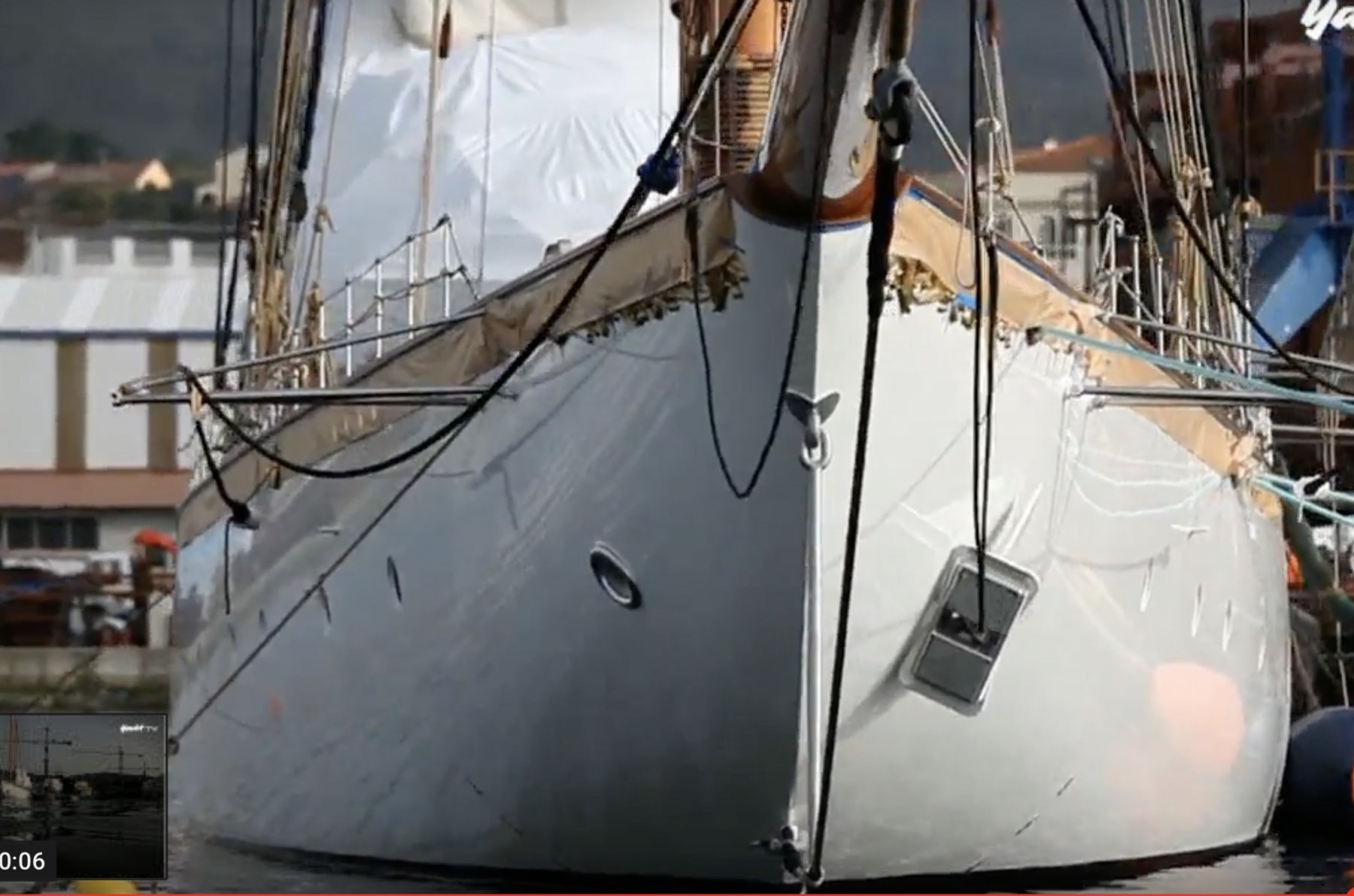
Roger - Im not sure what they did with Germania but none of the photos show any sort of oil canning.


-
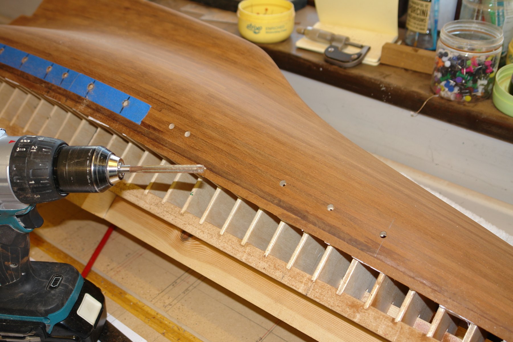
Hi John, Yes its a key skill these days. While training as a surgeon my son published a technical paper on the benefits of video gaming when learning the skills of key hole surgery. Apparently his seniors were quite impressed how quickly he picked it up. He explained that the trick was to forget your hands exist and "connect your brain" directly to the video screen. If I tried it I would probably get it wrong and connect the drill to my brain.
-
Paul, Pat, Gary, Druxey. Thank you, sometimes things work out when they could have gone badly wrong.
-
Chasseur - she has a steel hull but that aside your comments are still valid - thank you for your interest and comments. I am not sure about poured on epoxy as I don't have any experience of it. My current thoughts are multiple layers of wipe on poly which I have used before. It needs lots of layers and takes many days.
-
HMCSS Victoria 1855 by BANYAN - 1:72
KeithAug replied to BANYAN's topic in - Build logs for subjects built 1851 - 1900
Pat, I know why you think this and indeed I don't do it frequently but it isn't all that difficult to get it back to vertical. All you need to do is rough set the head back to vertical and then mount a bar in the chuck at right angles to the spindle axis. Attach a dial indicator to the end of the bar and the check the reading against table surface - swing the bar through 180 degrees and check the reading against the table surface. If the readings are different adjust the head verticality until they become the same. It might take some time when you first do it but with practice it becomes a 10 minute job. If unclear I can supply photos.- 1,013 replies
-
- 5
-
-
- gun dispatch vessel
- victoria
- (and 2 more)
-
Good progress Jon and interesting to follow - although I fear you are already on head two and handle 3.
-
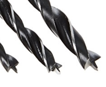
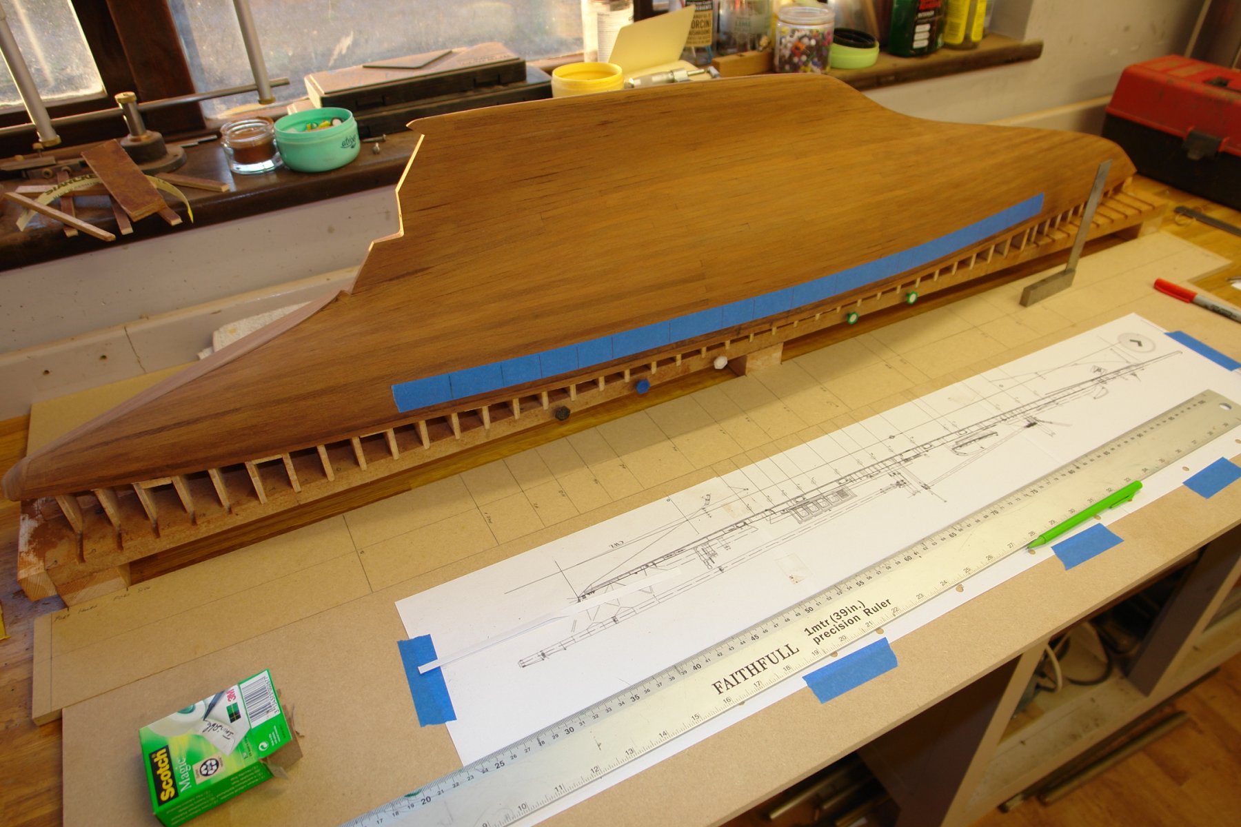
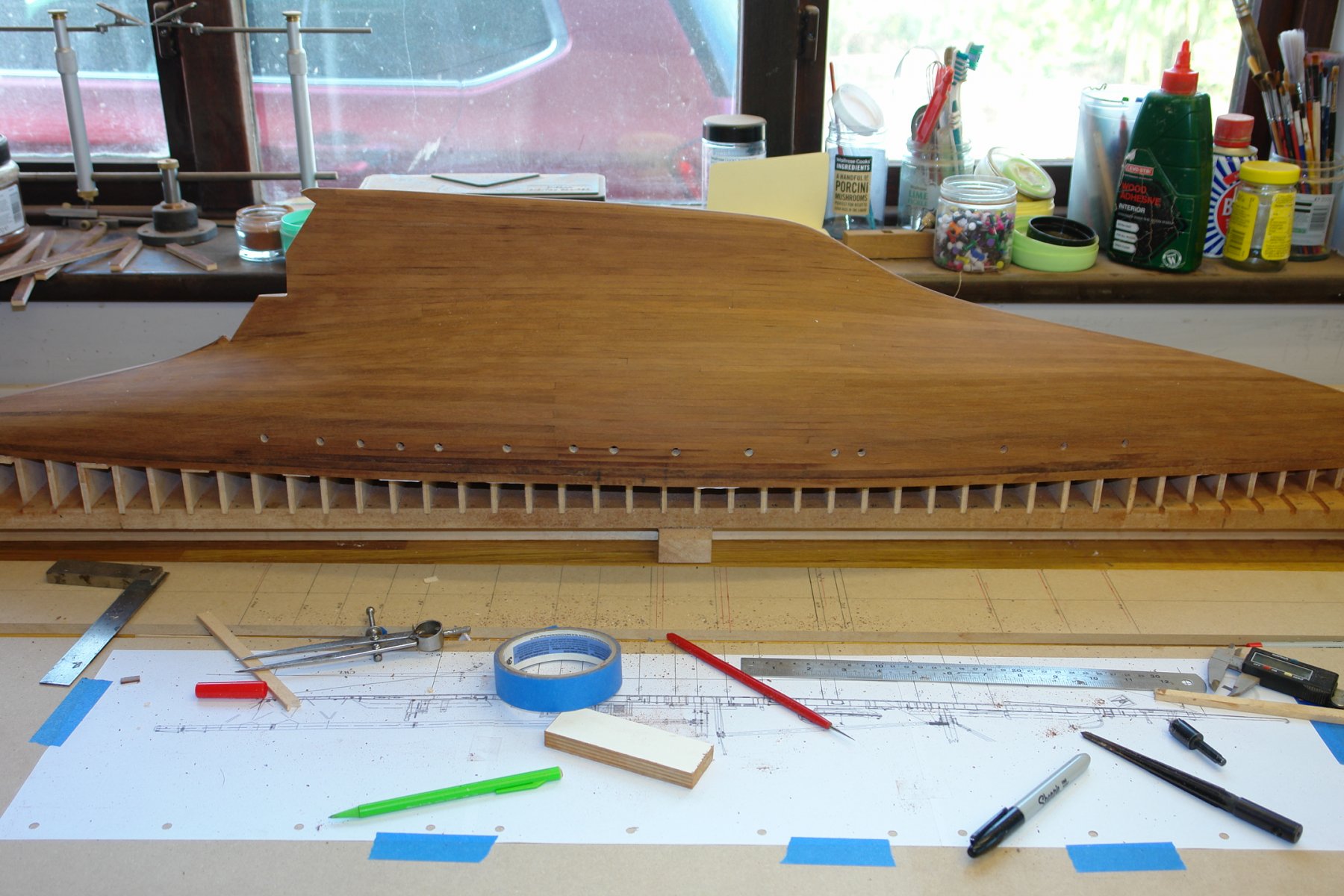
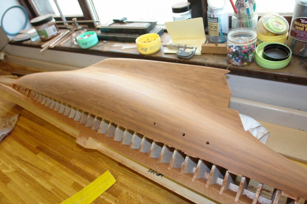
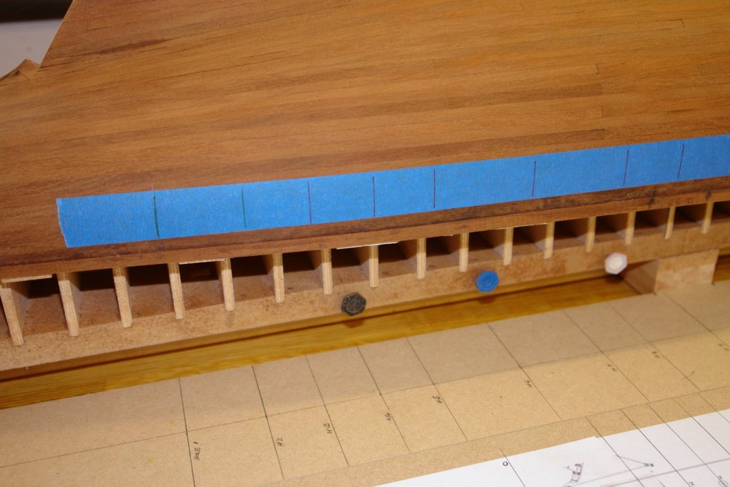
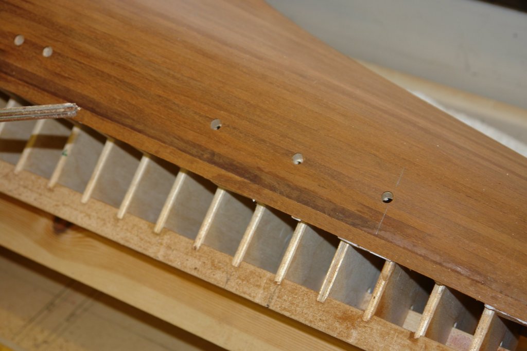
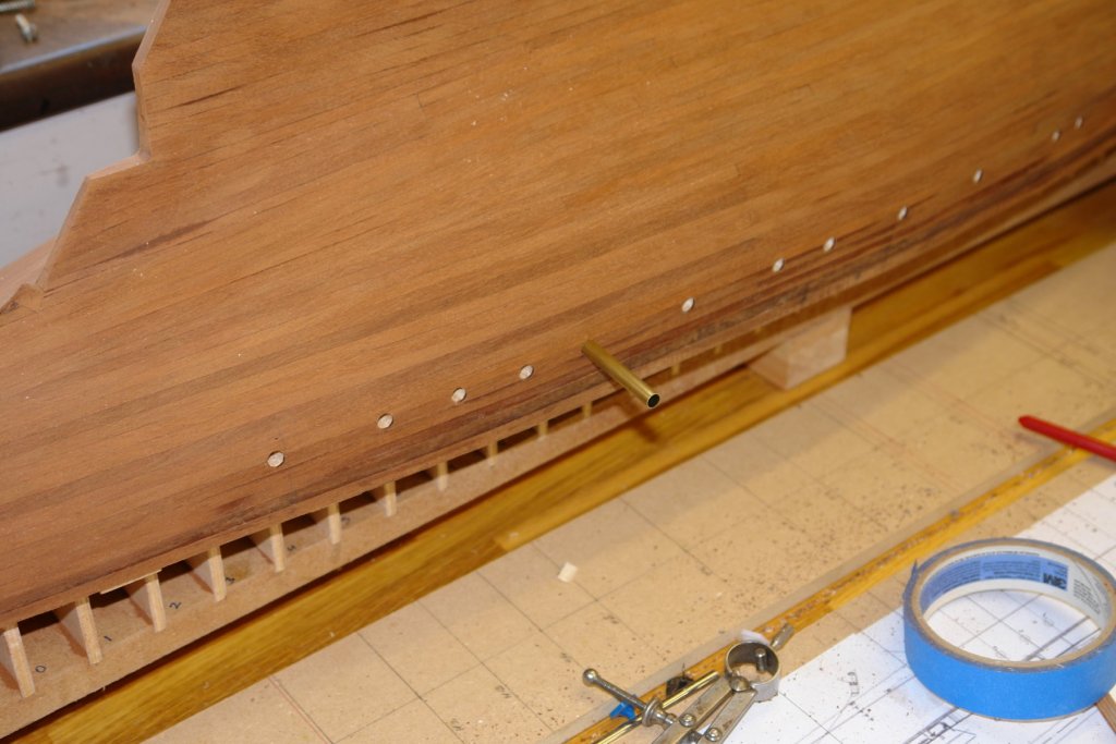
Planker's Progress 12 - Day 26. This I think will curtail the hole drilling debate - to be continued when I get to drilling the bulwarks. To position the portholes I transferred their axial position to a plank of MDF which I positioned alongside the hull. I also put a piece of masking tape on the hull with top edge laid on the top edge of the shear plank (upside down in the photo). On the plan all portholes are a fixed distance from the top edge of the shear plank with the exception of aft most two which are further away. The position of the portholes was ruled on to the masking tape using an engineers square. The vertical position was then marked with callipers. I then drilled using my pilot hole / multiple reamer method, up to 7mm. As previously explained the final size will be created using a conical sander. It worked but I am sure some of the suggested methods are better. I am wondering whether to give her a broadside armament!!!!!!!!!


-
Hello Pat - for realism painting is clearly the way to go. What I am going to do is see how the wood looks when varnished. If the grain is nice I will minimise the paint.
-
Hi Roger. Yes i can see that would work. With so many options I think we could collectively write a book on "how to make a hole in piece of wood.
-
Eberhard - I seem to remember the button method from my apprentice training days with Rolls Royce. I think this is also a good idea and will try it. For the pilot holes in method 1 and for the single drill in methods 2 / 3 I used proper wood bits. Dan - whenever I suggest I might paint the hull the mahogany zealots threaten to take a contract out on me. I am trying to keep the options open, but you are right that your method would probably guarantee the crispest finish. Maybe I should just go for a repeat of the Altair paint scheme?