


KeithAug
-
Posts
3,867 -
Joined
-
Last visited
Content Type
Profiles
Forums
Gallery
Events
Posts posted by KeithAug
-
-
11 hours ago, bricklayer said:
Is there a glass scale or magnetic scale attached underneath the cover?
Michael - yes it's a glass DRO scale. The mill has DRO on 3 axis fitted by myself for about £200. The surgery shouldn't be a problem - it's quite routine these days and only tales about 20 minutes under local aesthetic.
-
-
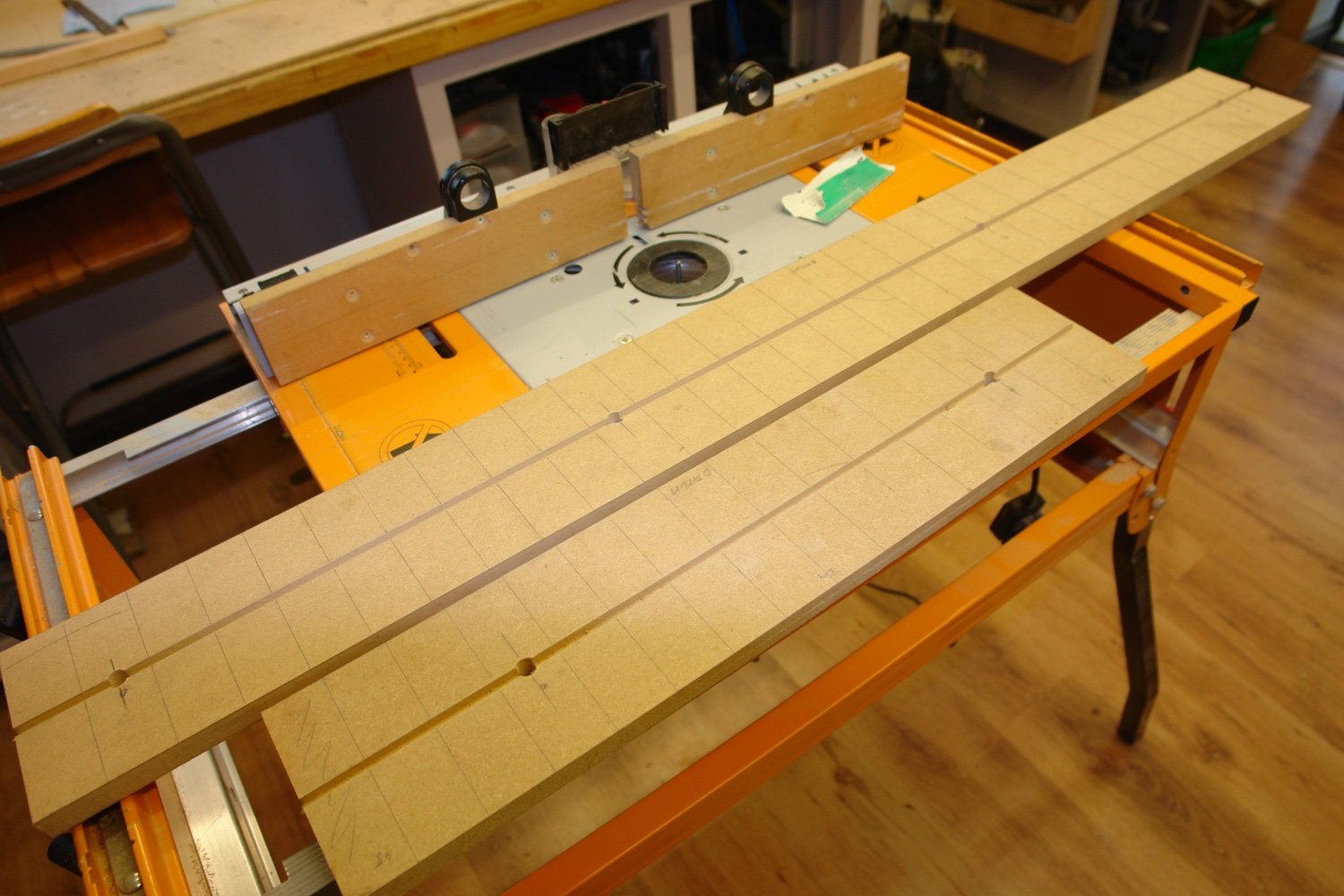
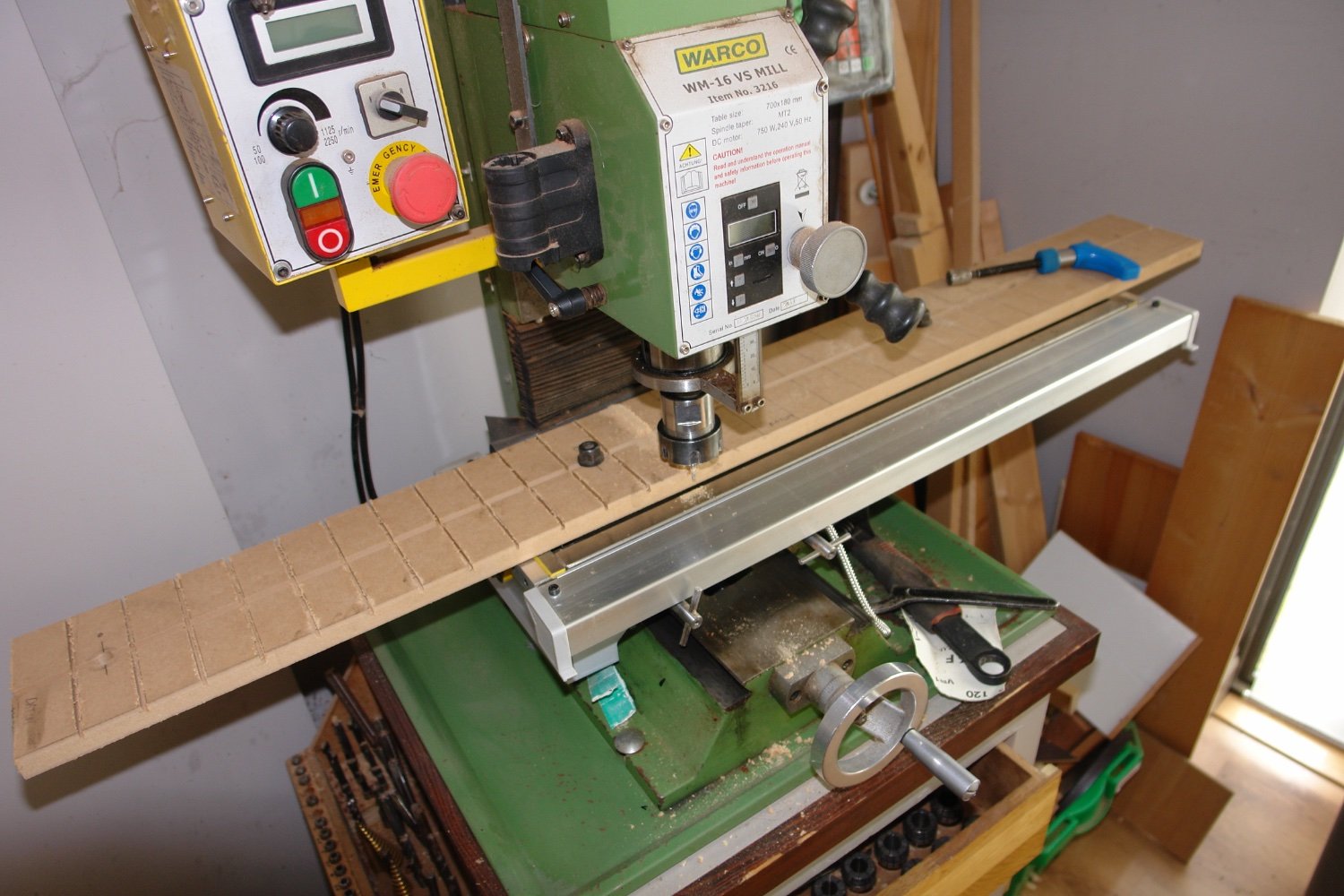
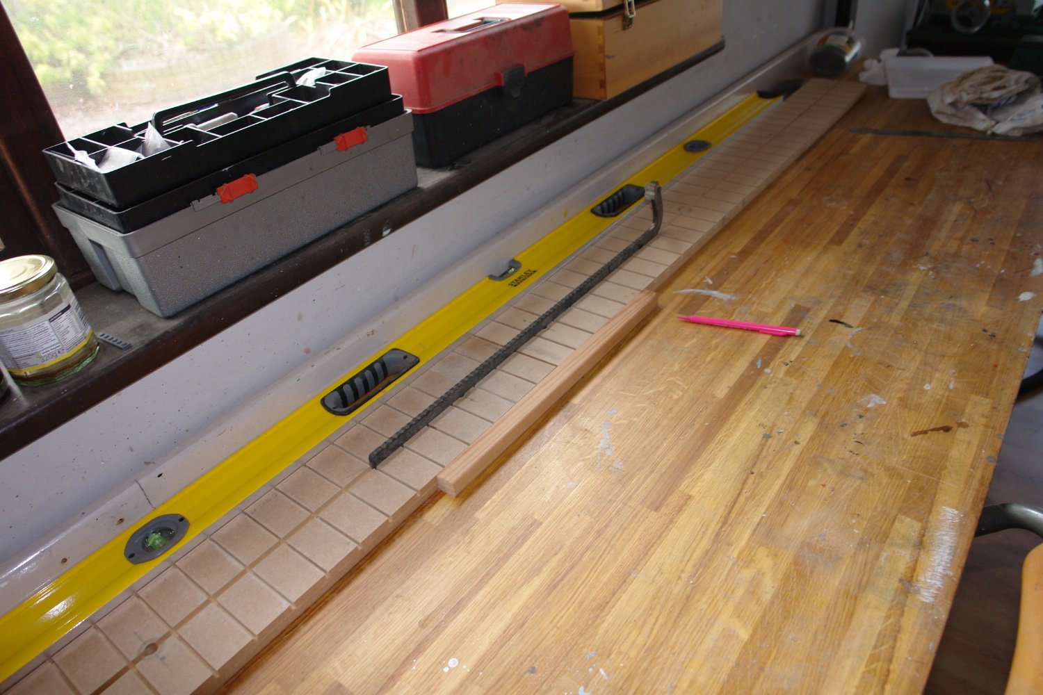
Well I suppose it's about time that I started to make some sawdust, even though it is only the building board. It will be 5" wide by 6' long by 3/4 inch thick. The hull beam is about 9" so the sides will overhang. The length is about 6" longer than I need. The board will be made from 2 pieces of MDF fixed end to end. This is because I don't have a 6' piece handy, however it does ease the machining on the mill which only has a nominal capacity of 18".
I started by cutting two board to give a combined length of 6'. I also drilled two/three 10mm holes in each board to take the bolts for clamping the boards to the mill table,
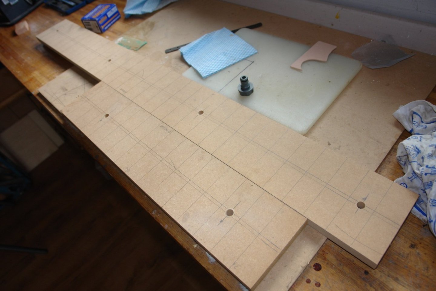
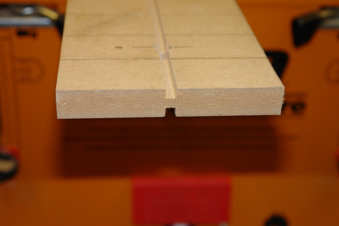
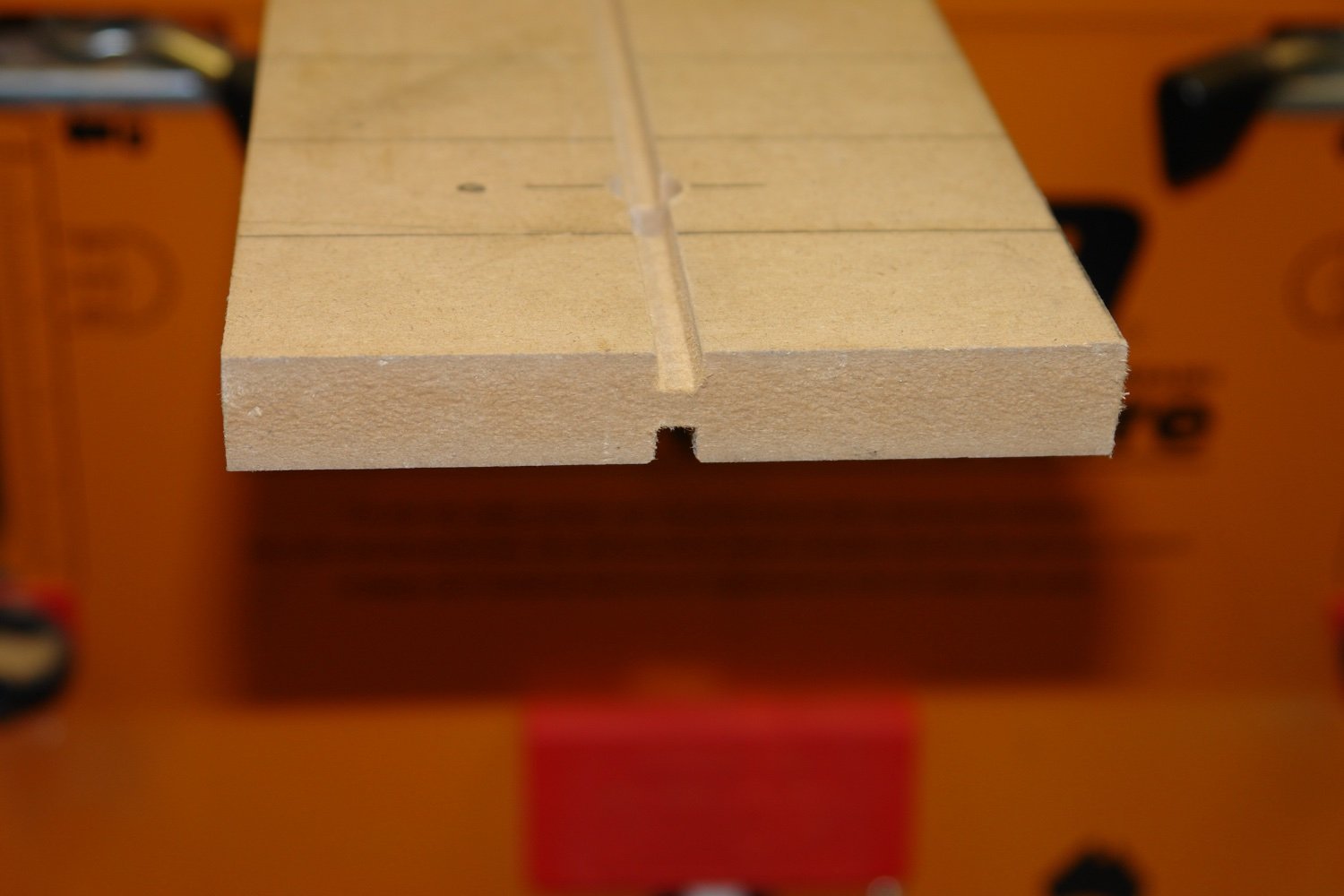
I then routed a 1/4" longtitudinal slot in each side of each board 1/4" deep.
 Both slots were cut from the same datum edge to ensure the top and bottom slots aligned.
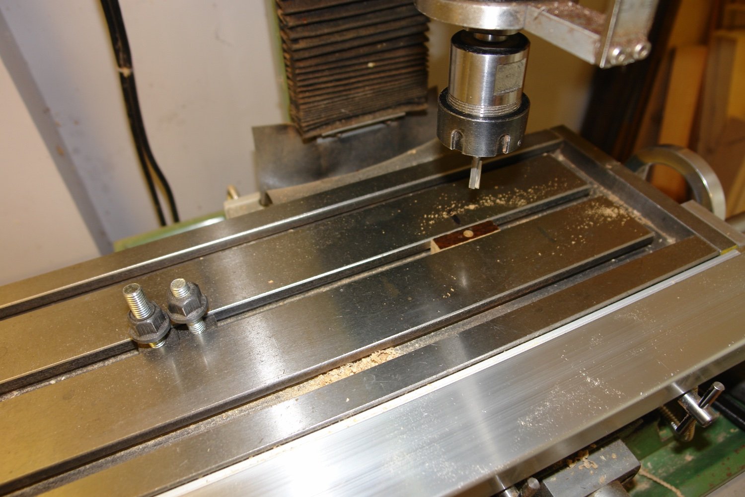
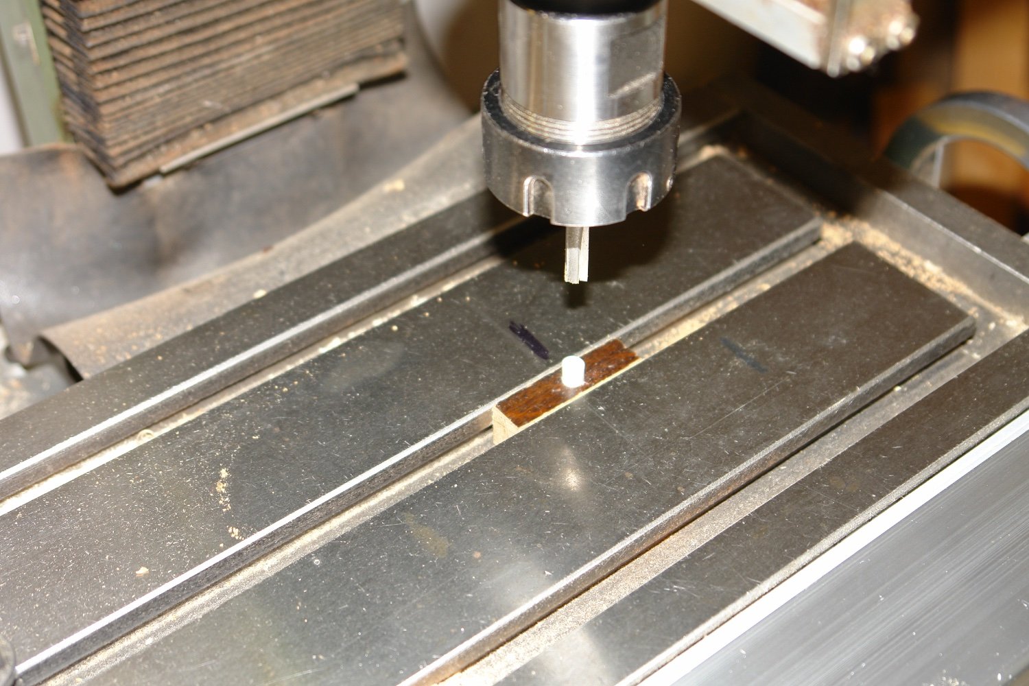
I then cut 2 wooden blocks to fit tightly in the mill table central slot and hammered them in place. I then drilled each block with a 1/4" hole using the same X axis setting.

Once drilled each block had a 1/4"diameter peg inserted.

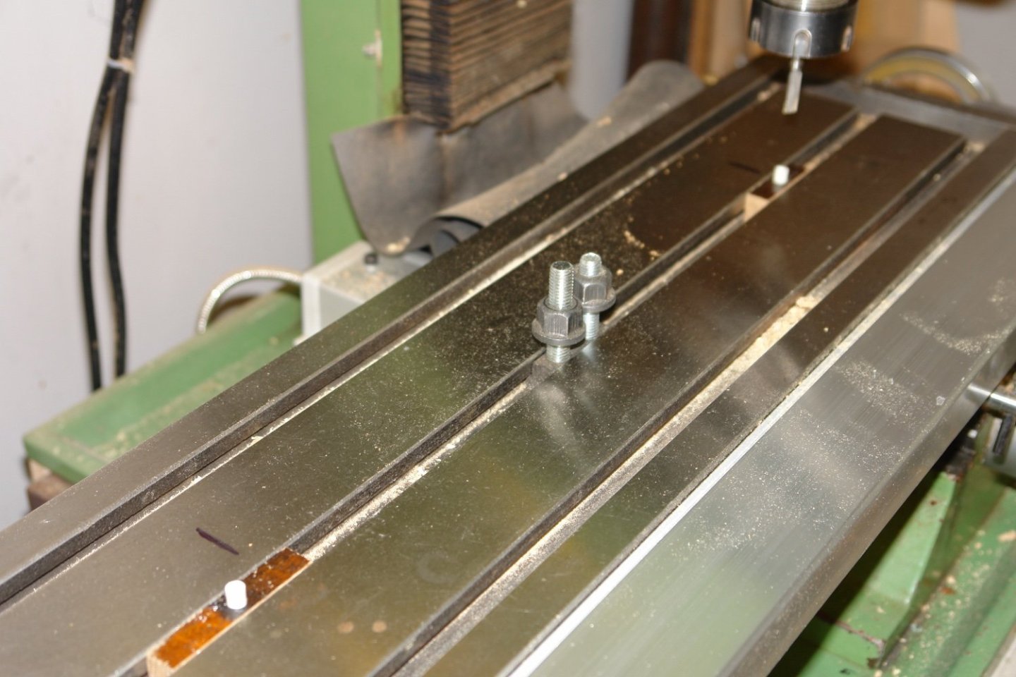
These pegs fit into the lower slots in each building board, allowing the board to slide in the X direction while maintaining it at right angles to the table. This then allows the board to be cut over a much greater length that the limitation of the 18" X axis travel of the mill. (The mill table X axis handles however have to be removed for the longer of the 2 boards).

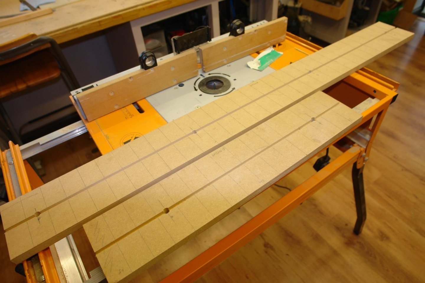
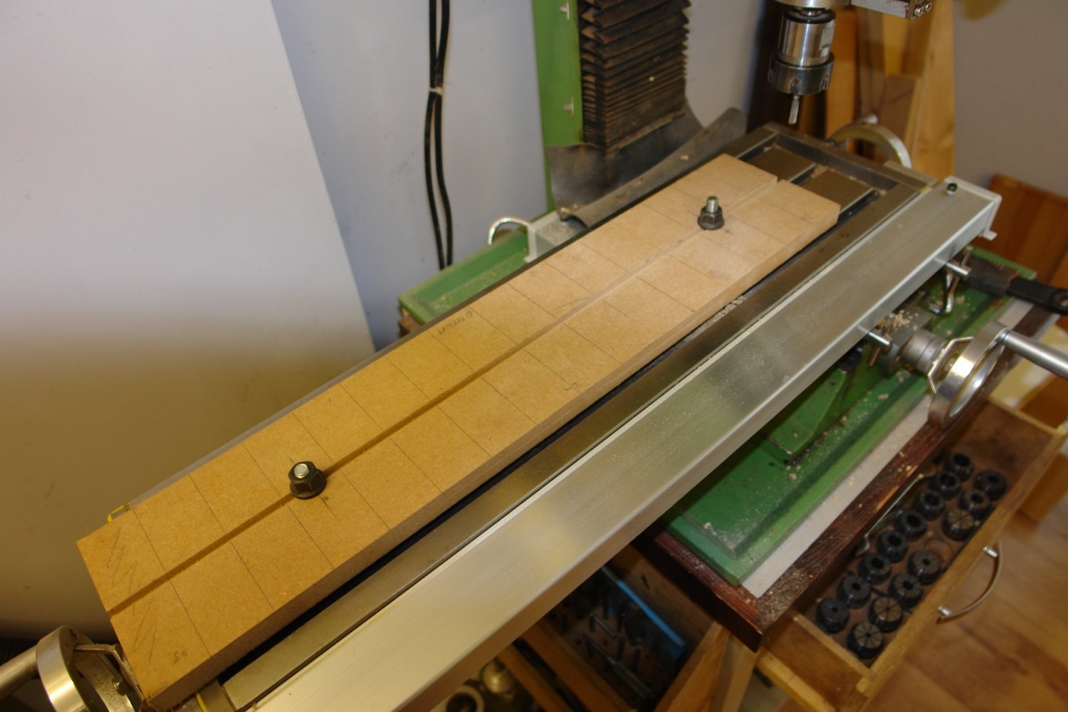
The frames are going to be cut from 1/8" ply (because I have some left from a previous project). So slots are cut across the board 1/8" wide by 1/8" deep by 5" long. The mill Y axis travel is 6" so the 5" board width is a convenient size.
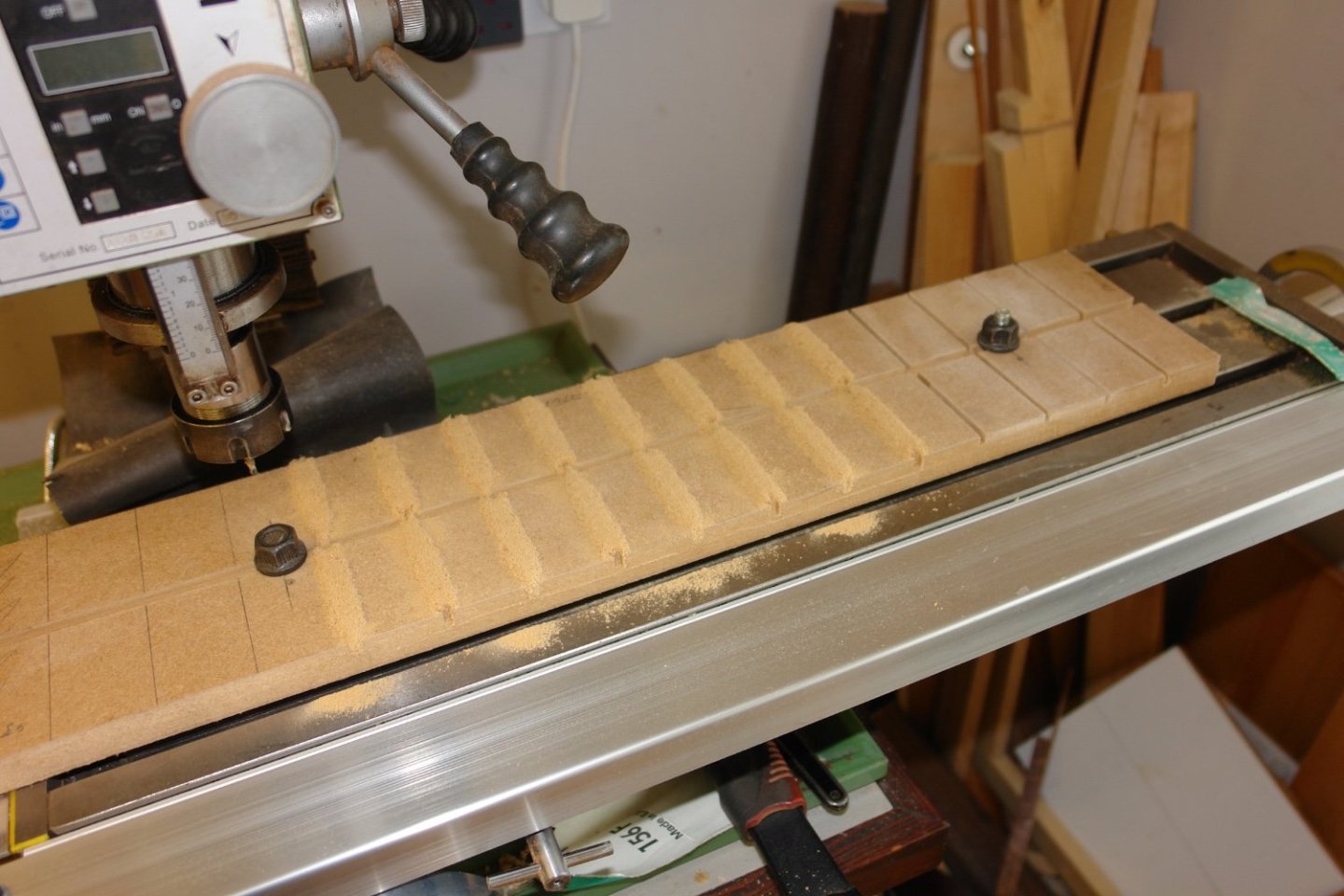

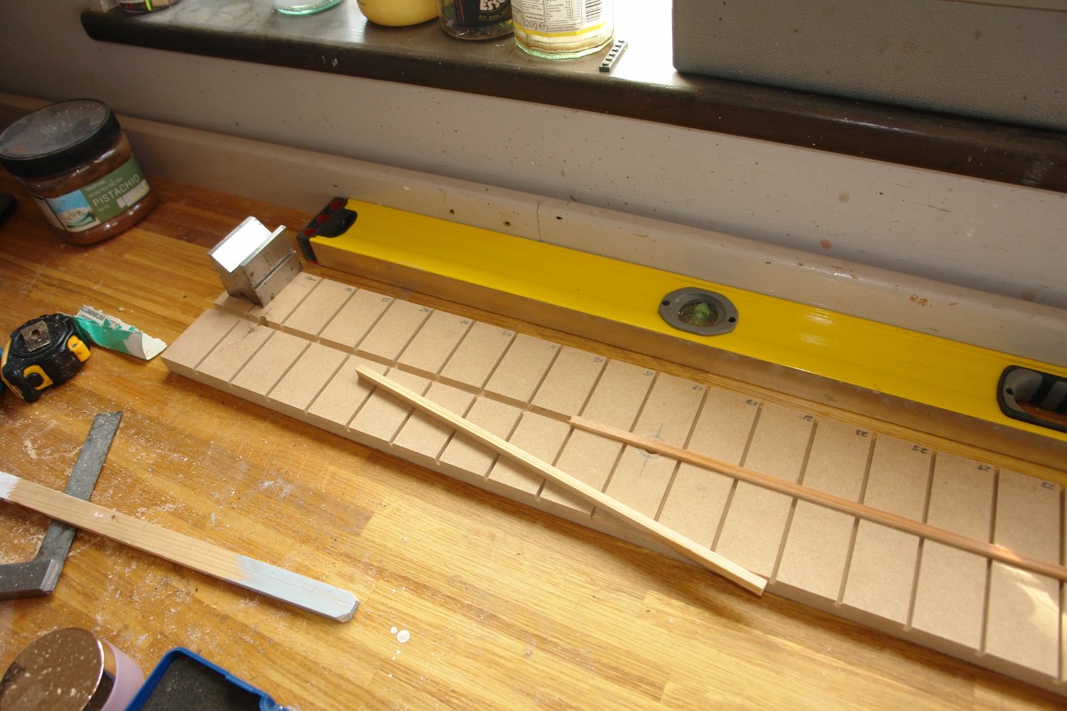
Once cut the boards were cleaned up and aligned against a 6' straight edge. Side pieces were then glued in place to join the boards.

The upper central slot then had 1/4" strip wood inserted to locate the central notch in the frames.

This might all seem to be overkill but it does make the task of keeping the frames aligned and at right angles very simple. The sharp eyed among you will notice i have numbered the slots with the frame numbers. Hopefully I will put the correct frames in the correct slots.
- FriedClams, mtaylor, GrandpaPhil and 14 others
-
 16
16
-
 1
1
-
Thank you all for the good wishes. My wife was done earlier this year and ever since she has hiding the mirrors and complaining about the decor. I still think she is 21. 😱
- FlyingFish, Keith Black, BANYAN and 3 others
-
4
-
 2
2
-
Very impressive. Not long now until you finish. What next?
- FriedClams, mbp521, mtaylor and 1 other
-
4
-
-
21 hours ago, TBlack said:
Take all the time you want,
I don't have a lot of choice art the moment Tom. I'm waiting for cataract surgery on both eyes and struggle with accuracy when cutting out stuff. I will have about 8 weeks off from dust making once the surgery takes place, in the mean time I eagerly await the appointment. Im actually looking forward to getting it done but may be less enthusiastic once I see myself in the mirror. At the moment I delude myself that I am still a bit of a catch 😁. It is good to think that at least one of the problems of aging can be reversed.
- Keith Black, mtaylor, Retired guy and 3 others
-
6
-
-
-
-
Very smart looking model Grant. Excellent work.
-
27 minutes ago, helmarsowick said:
I was wondering if you can help me.
Helmar
You might want to get "The Gaff Rig Handbook" by John Leather. You can usually find a second hand copy at a decent price. It will give you a lot of information on rigging.
-
13 minutes ago, Jim Lad said:
About time you got back to work!
Yes sir!
- mtaylor, Keith Black and Jim Lad
-
3
-
50 minutes ago, Wintergreen said:
c**p weather and engine troubles.
What a pity, but there is always next year.
- Keith Black and mtaylor
-
2
-
After a further shipyard layoff I return once again to building. I had now drawn all the frame templates. Some will be solid frames but most will have internal cut outs to facilitate below deck detailing. by way of example here is frame 37.
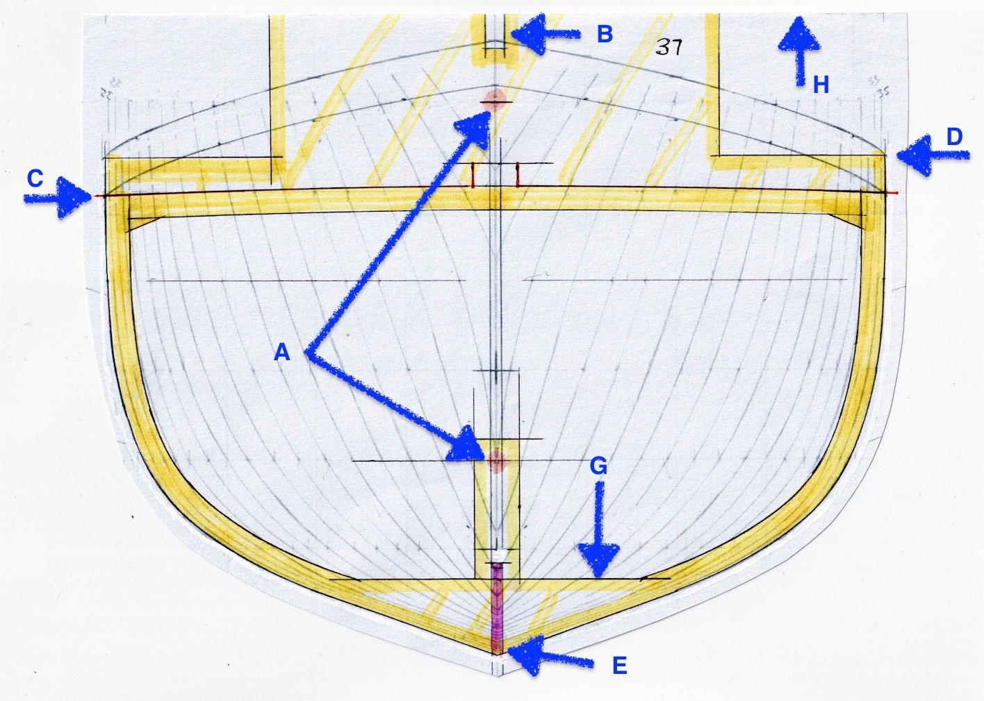
At points A and B i will drill 6mm holes to take silver steel alignment rods to me used during assembly of the skeleton.
At point B is a further alignment slot to locate the frame on the building board.
At C is the cut line for the upper edge of the deck beam. The cut will be made as far as the centre line lug, leaving only the lug to be cut through to release the building board up-stand.
D is the level of the top of the bulwark.
E is the slot for the keel.
G is the level of the interior deck (In the case of frame 37 this is the engine room floor level).
H is the datum surface for mounting on building board.
You might recall from earlier that I am only using half the frames that appear on the original. The spacing at model scale is 1.5" or 3 feet at full size. I have included all the frame cutting templates for those who might want to build Cangarda in future.
Template, 05, 07, 09,.tiffTemplate, 11, 13,.tiffTemplate, 15,.tiffTemplate, 17,.tiffTemplate, 19,.tiffTemplate, 21,.tiffTemplate, 23,.tiffTemplate, 25,.tiffTemplate, 27,.tiffTemplate, 29,.tiffTemplate, 31,.tiffTemplate, 33,.tiffTemplate, 35,.tiffTemplate, 37,.tiffTemplate, 39,.tiffTemplate, 41,.tiffTemplate, 43,.tiffTemplate, 45,.tiffTemplate, 47,.tiffTemplate, 49,.tiffTemplate, 51,.tiffTemplate, 53,.tiffTemplate, 55,.tiffTemplate, 57,.tiffTemplate, 59,.tiffTemplate, 61,.tiffTemplate, 63,.tiffTemplate, 65,.tiffTemplate, 67,.tiffTemplate, 69,.tiffTemplate, 71,.tiffTemplate, 73,.tiffTemplate, 75, 77,.tiffTemplate, 79, 81, 83,.tiffTemplate, Bow, 01,03,.tiffTemplate, Stern,.tiff
-
-
She certainly is a bit of an ugly duckling, but nevertheless quite cute. I look forward to the build.
- Ras Ambrioso, mtaylor and Canute
-
3
-
Sorry to be joining a little late Valeriy. I look forward to more posts.
- Canute, mtaylor, FriedClams and 2 others
-
5
-
On 11/14/2023 at 10:05 PM, mbp521 said:
used a light weight air drying clay to fill in between the bulkheads,
That's novel Brian. I have not seen that before. As you say the result looks really sharp. I guess she is quite stern heavy - a common problem! 😀
- Keith Black, mtaylor, FriedClams and 2 others
-
5
-
Good progress Pat. The brass work looks very good. I enjoyed catching up, thank you. The bending jig for PE looks like quite an easy workshop project.
- Glen McGuire, mtaylor, Keith Black and 1 other
-
4
-
-
Superb work as ever. loved the anchor buoys and the rails. The images of the gun emplacement are wonderful. You ended your summer break much sooner than I.
- Keith Black, mbp521 and mtaylor
-
3
-
As usual a great model Dan - but alas a tragic story.
- Canute, Keith Black, mtaylor and 1 other
-
4
-
Good to find I haven't missed much during my absence. I'm looking forward to seeing her develop.
- Scottish Guy, Jack12477, Mark Pearse and 1 other
-
4


SS Blagoev ex-Songa 1921 by Valeriy V - FINISHED - scale 1:100 - Soviet Union
in - Build logs for subjects built 1901 - Present Day
Posted
Valeriy - As Eberhard says - I must do more brass work to develop my skills. Very inspiring. It would be good if you were able to supply more detail on your build / soldering sequence. I'm interested in how you make the later joints without unsoldering the earlier work?
Also it would be interesting to know why you chose brass for the deck planks rather than something else e.g. very thin birch ply or even card?