


KeithAug
-
Posts
3,405 -
Joined
-
Last visited
Content Type
Profiles
Forums
Gallery
Events
Posts posted by KeithAug
-
-
I am surprised that such a small ship had 3 screws. Interesting - do you know why?
- lmagna, Canute, Andrew Egan and 1 other
-
 4
4
-
I think you undersell your CAD skills. Impressive.
- Wintergreen, druxey and mtaylor
-
3
-
7 hours ago, AKRYPTO said:
The Ship will be in 1:72 scale and will be a functional RC model.
Have you made the hull from scratch? - looks very professional.
- lmagna, mtaylor and thibaultron
-
3
-
On 2/15/2022 at 9:07 PM, Jond said:
I am off sailing in Florida
Sounds great, I’m jealous.
-
Thank you all for the likes and comments. The leather preparation advice is noted and will be put to good use when I get round to finishing the saddles.
I decided it was about time for a bit of rigging. Learning from my last build I plan to change my approach. The fore and aft rigging will be done first, then the sails will be mounted and finally the shrouds will be fitted.
The fore and aft rigging will be done with Beadalon multi-stand steel plastic coated wire.
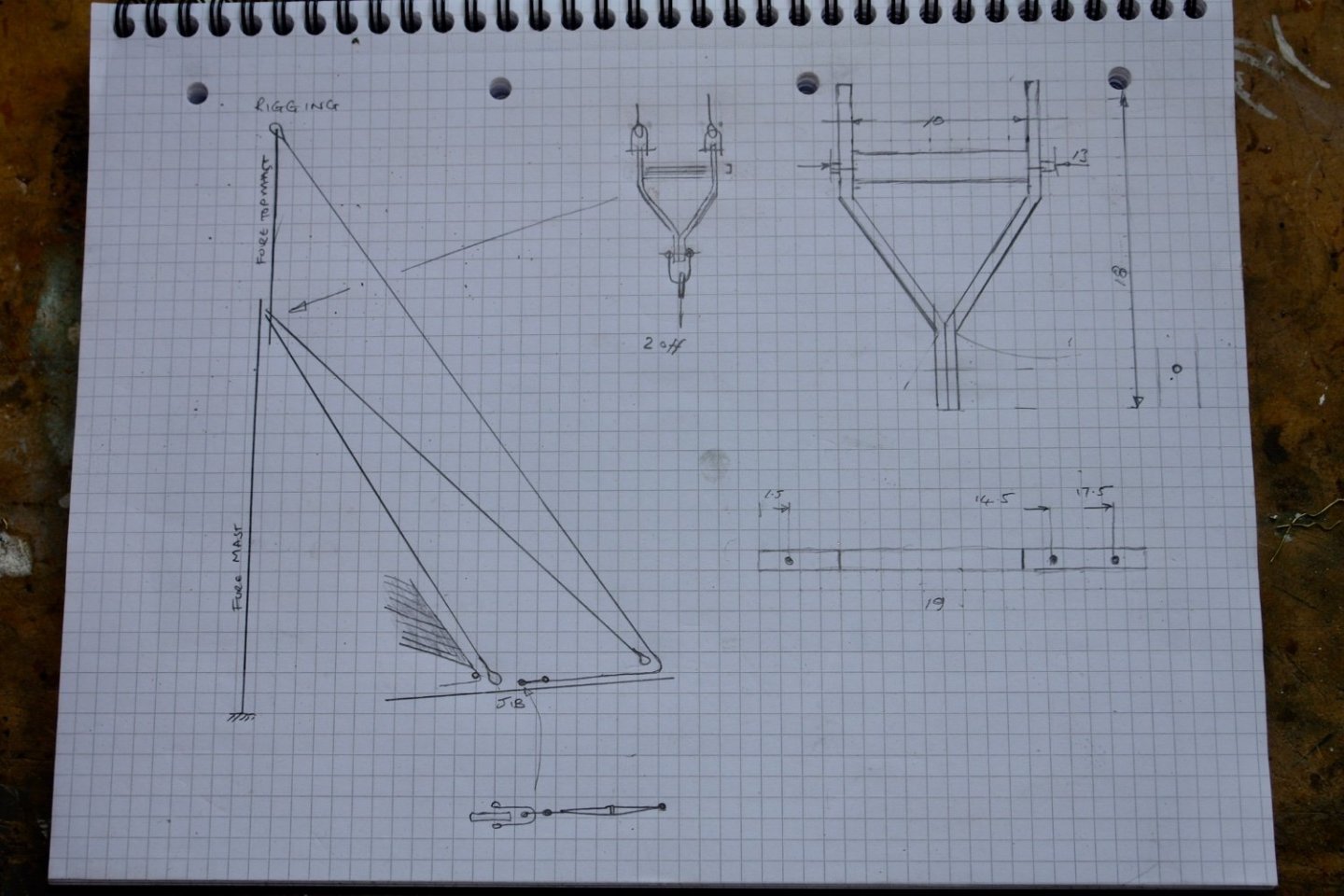
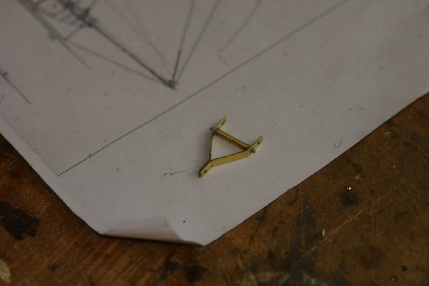
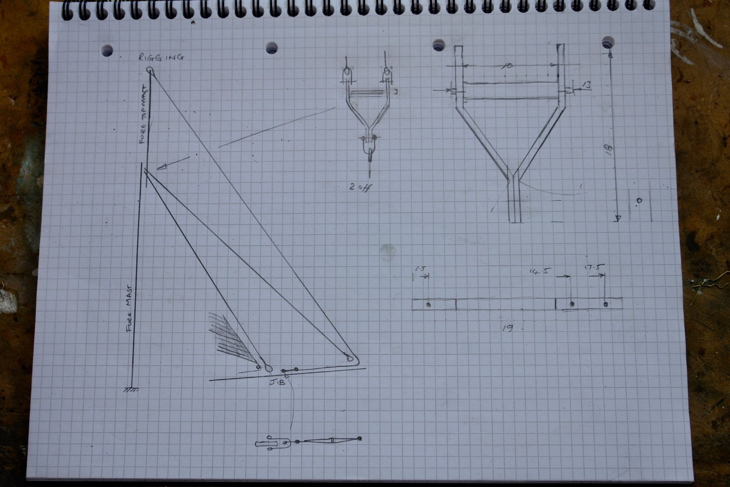
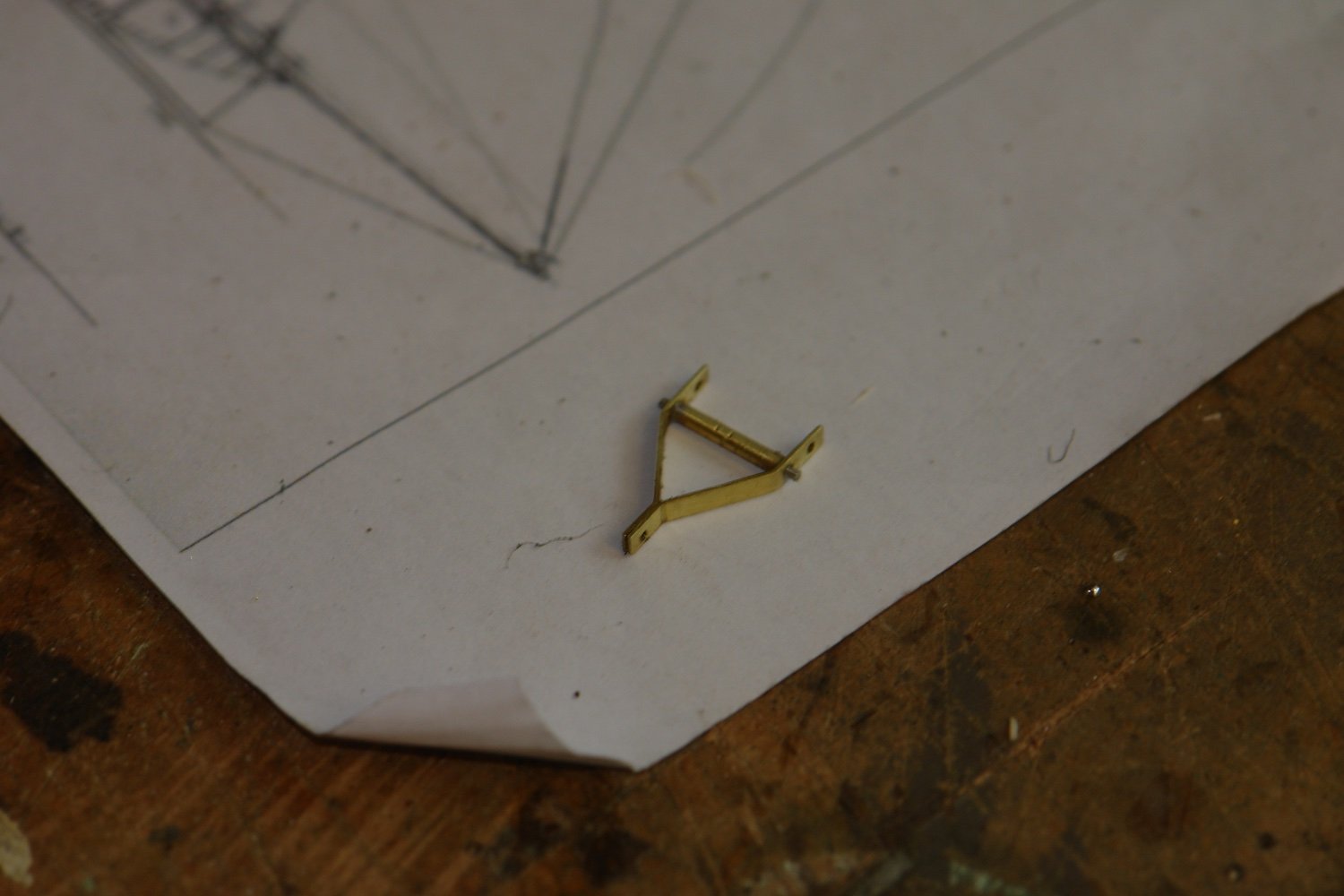
Before starting I needed to make a number of spreaders. Four of these are needed and their purpose is to prevent the stays from the main and fore masts binding on the upper masts.
The sketch below shows their form and their position on the fore mast.
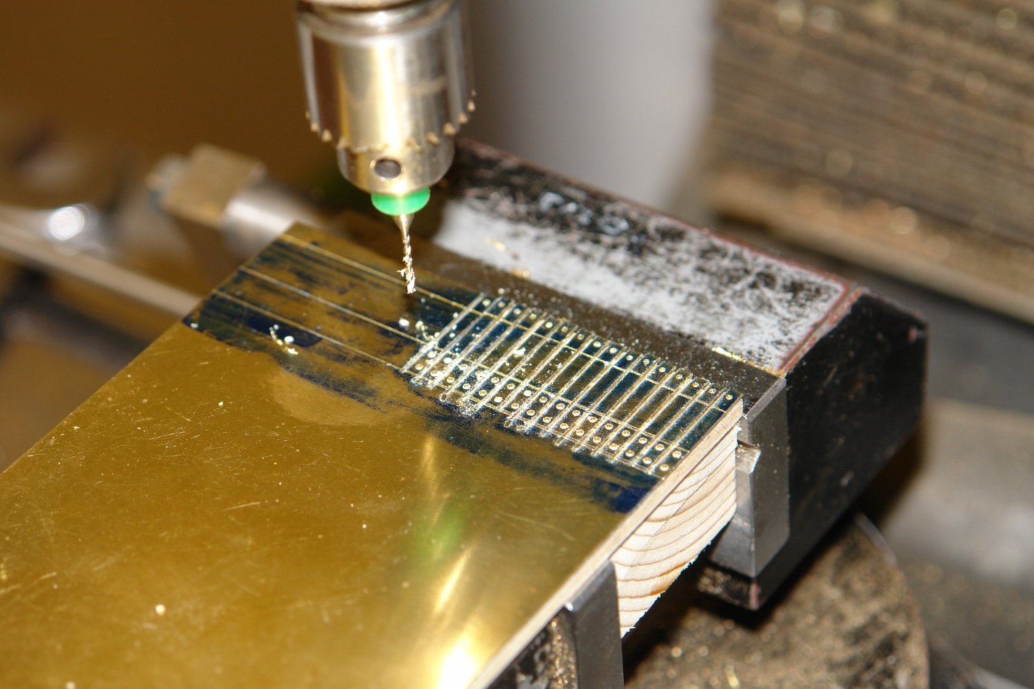
The frame part of the spreaders was made form .016" brass sheet. This was marked out and then glued to a piece of scrap !/8" ply. Strips of the correct thickness were then cut on the table saw.
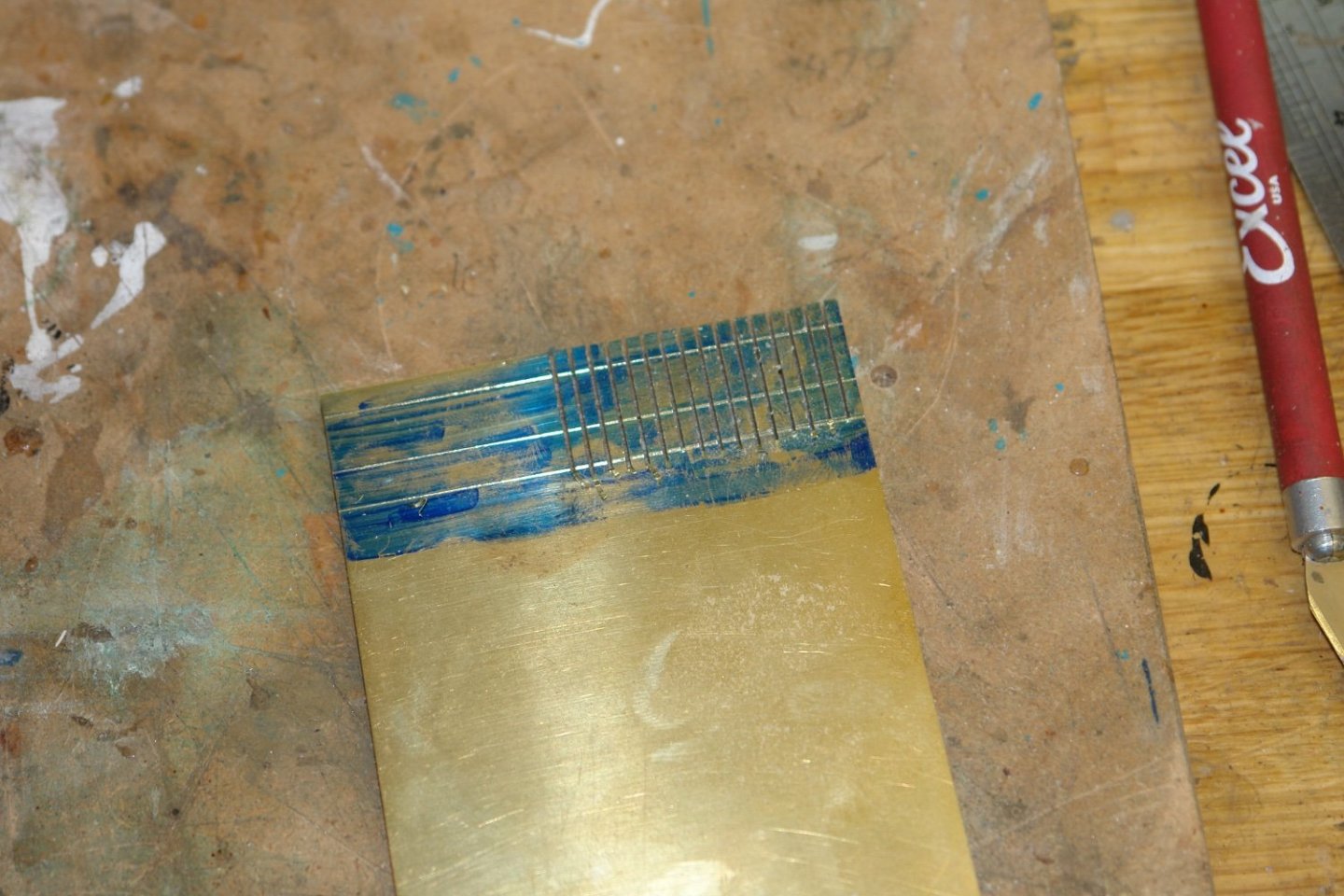
1mm holes were then drilled to locate the spreader bar and attach the 3 shackles.

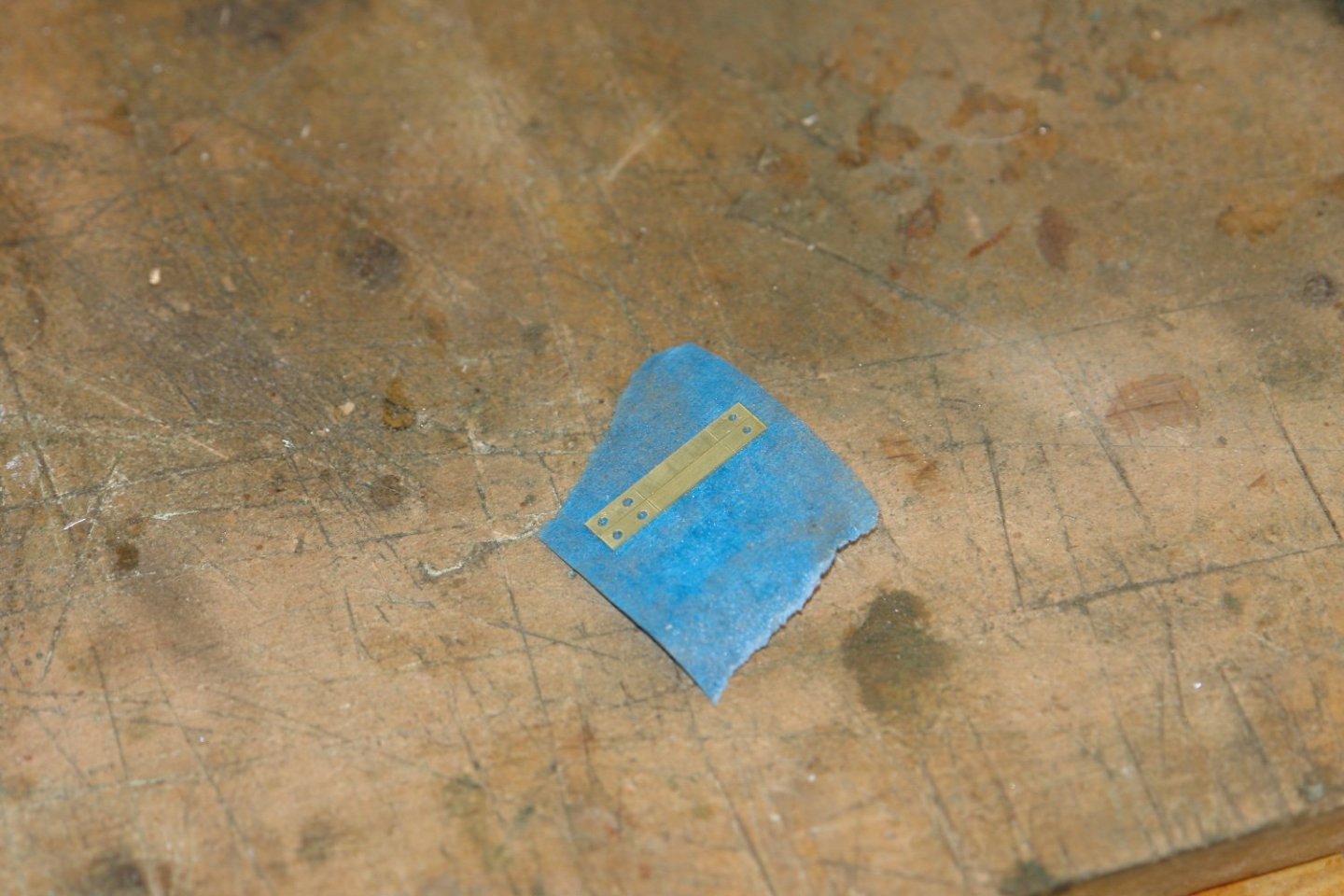
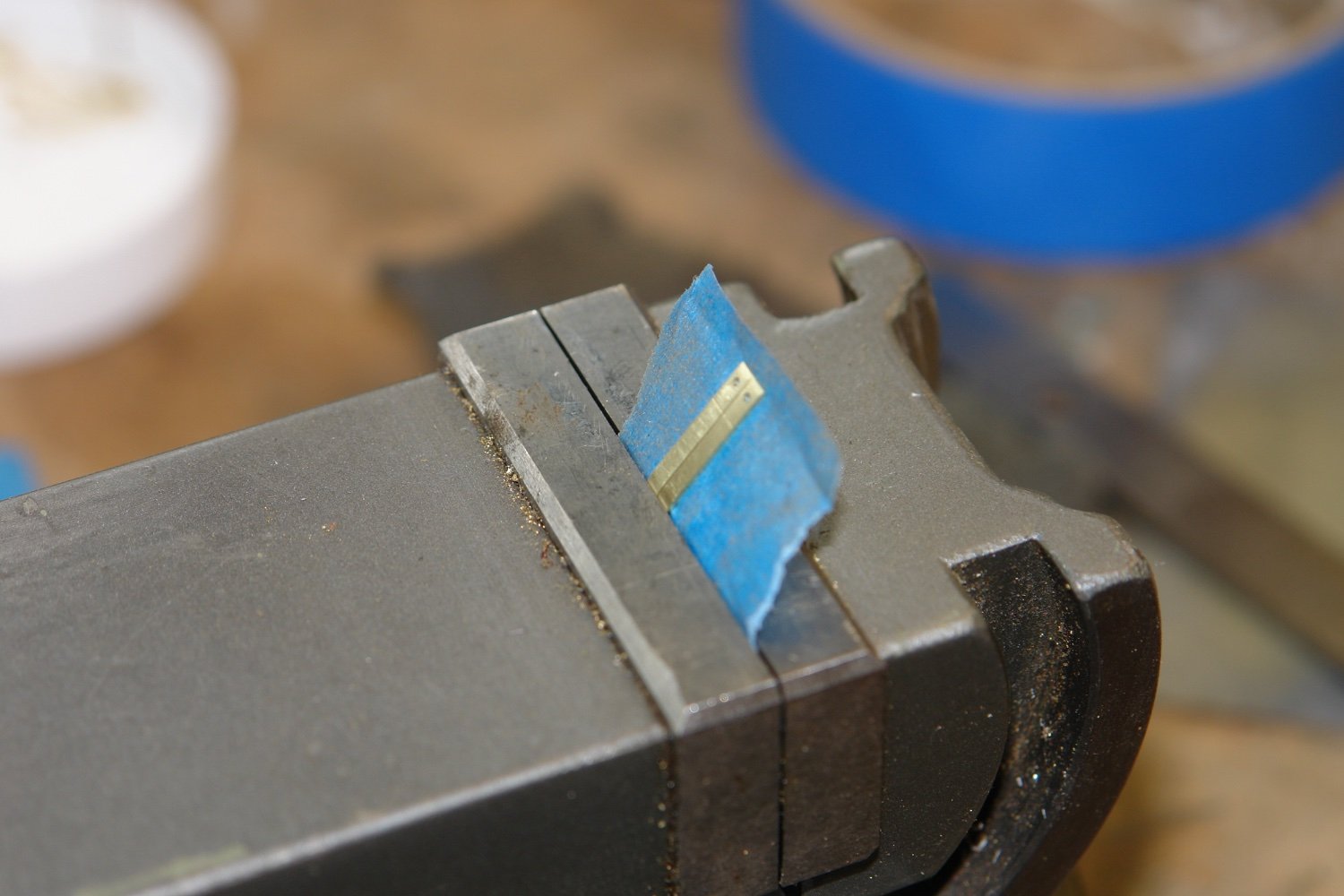
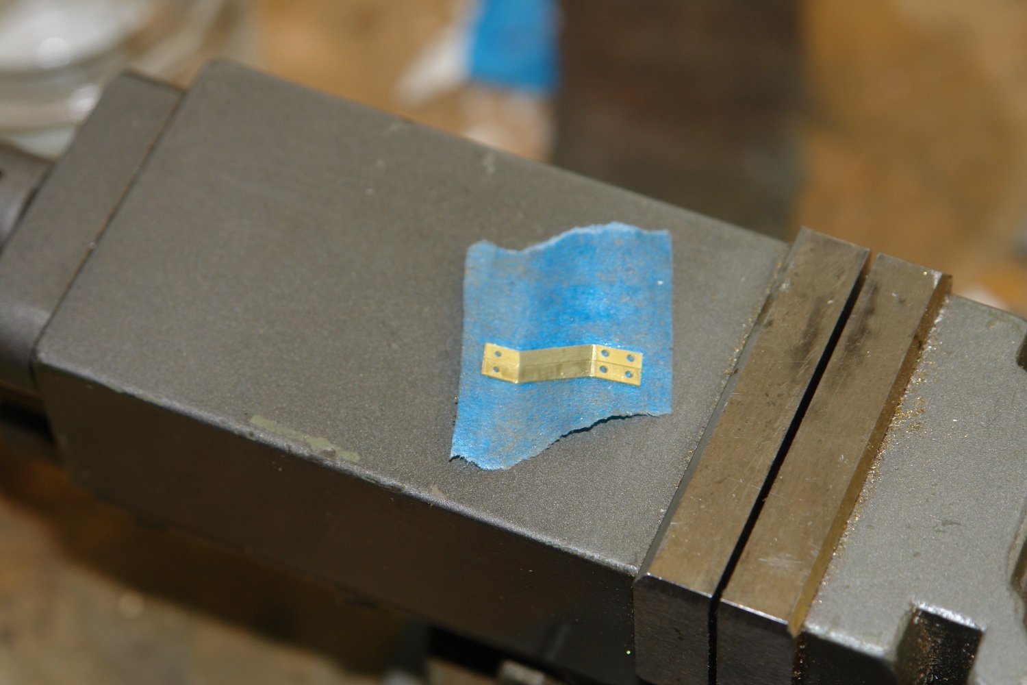
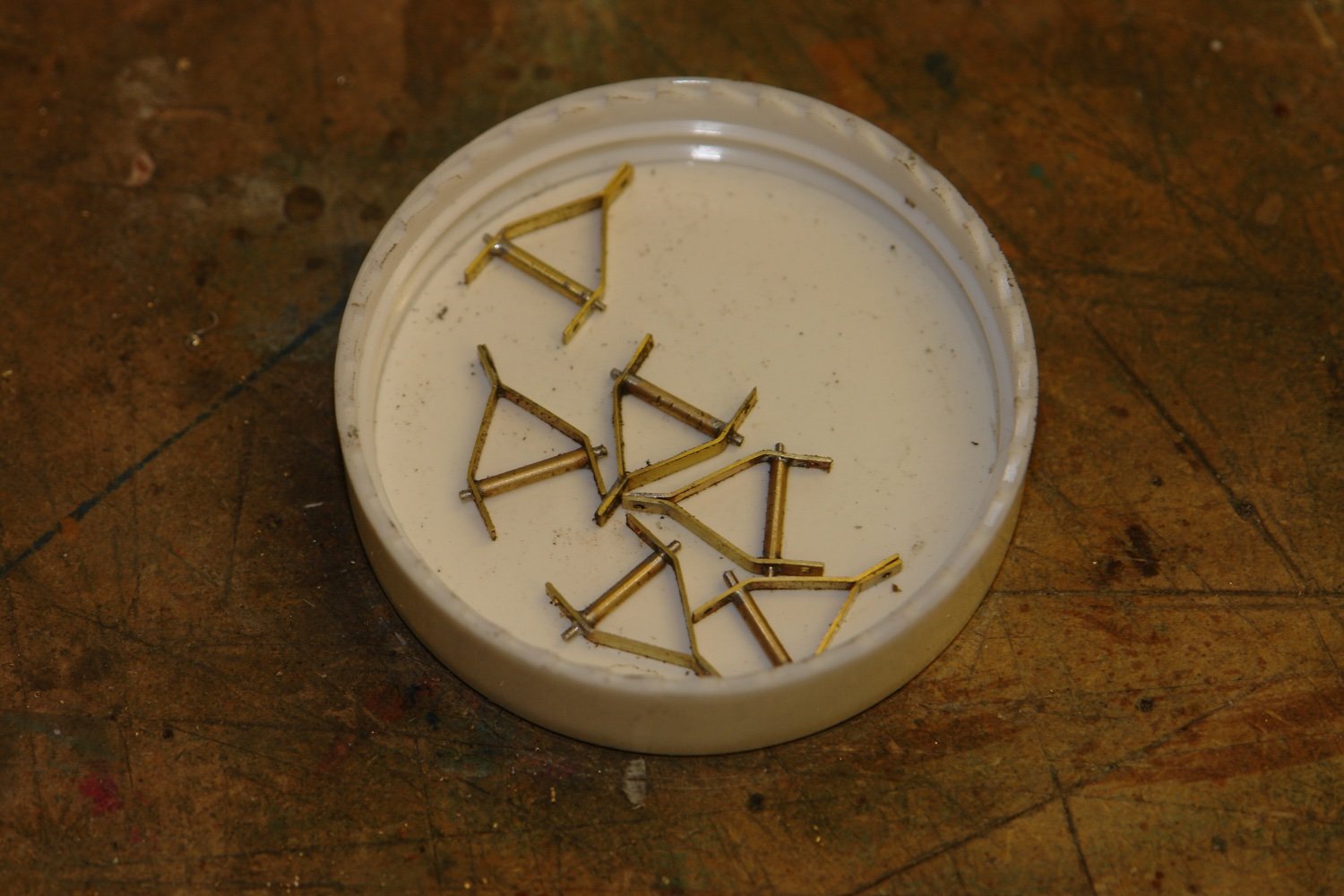
To get the symmetry correct I bent the strips in pairs. To ease handling I stuck each pair to a piece of masking tape before bending.


I kept the matched pairs together with a piece of wire.
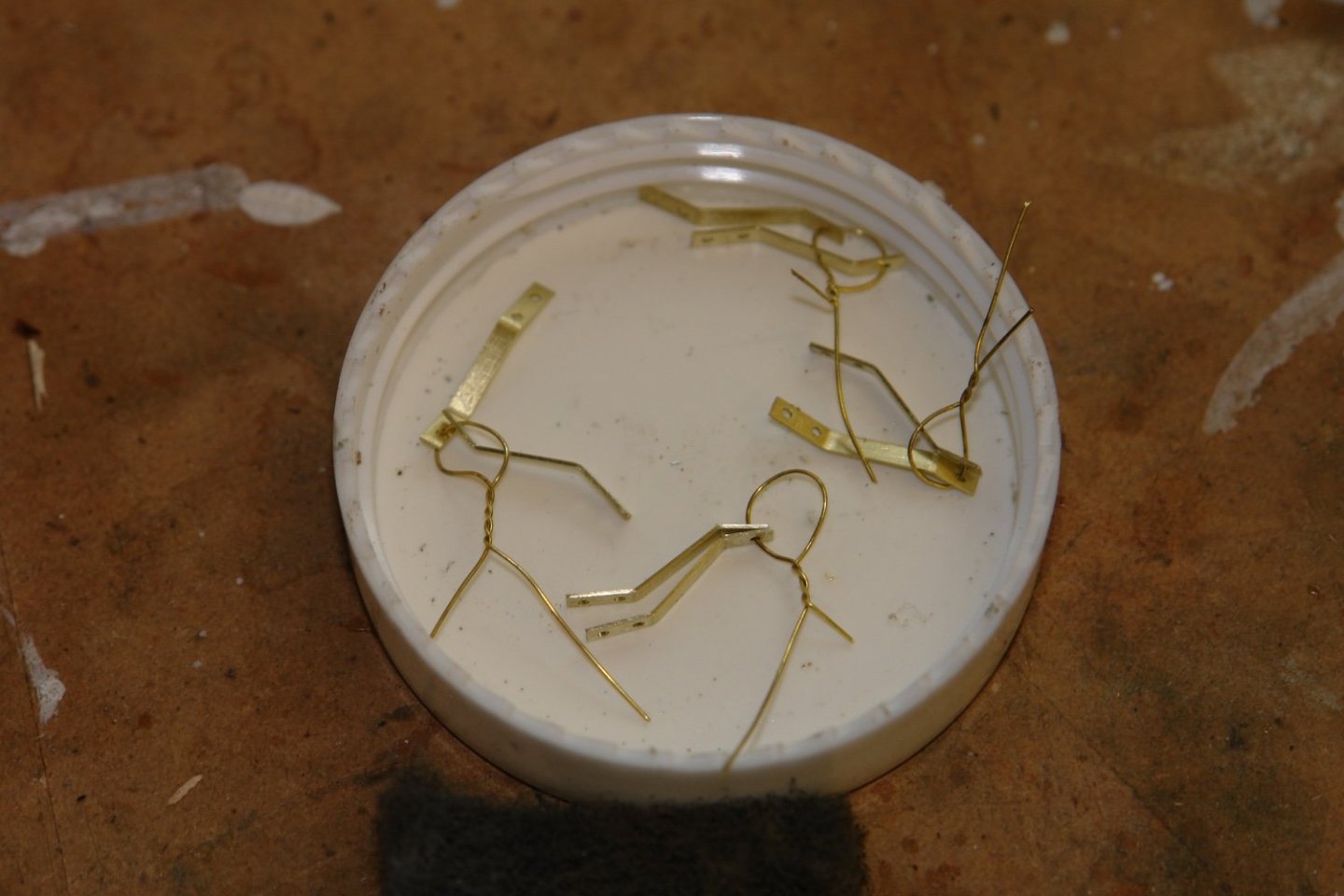
The spreader bar was turned from 1/16" brass rod and the sides / spreader bar were soldered together to form the spreader.
I only think I need 4 but made 6 just in case.

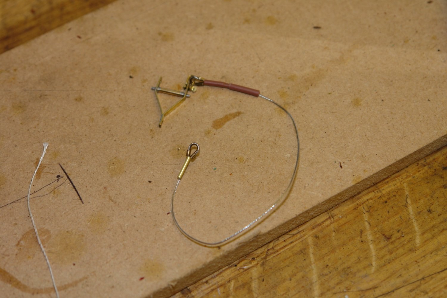
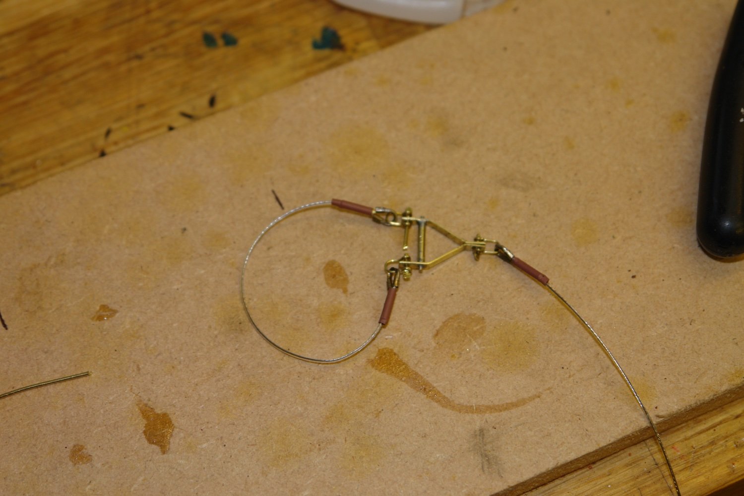
I then bent up shackles form .020" wire and made strops from the beading wire, wire guards and heat shrink tube.

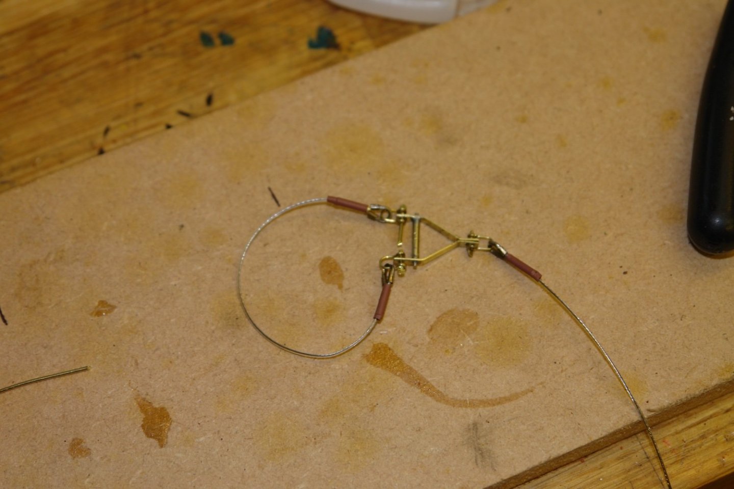
And that is as far as i got.
- JOUFF, Keith Black, ccoyle and 15 others
-
18
-
Keith - you came out the other side of Hell. Well done - they look pretty good to me.
- FriedClams, lraymo, Keith Black and 1 other
-
3
-
 1
1
-
3 hours ago, wefalck said:
Something I learned from playing around with the Märkline machine was that it is better to put the crank (I am not intending to motorise it for the time being) onto the connecting shaft, rather than onto to the short shaft
Yes that makes obvious sense from a mechanical engineering point of view.
- FriedClams, mbp521 and Keith Black
-
3
-
12 minutes ago, wefalck said:
I also considered making the gears myself, I do have a M 0.5 hob, but perhaps that's too much effort for such a tool and would delay completing WESPE even further ...
Eberhard
There seems to be a buoyant market in self build CNC router parts which include shafts, bearings, structural members, lead screws, gear and toothed belt drives etc, etc. they are all fairly cheap. You might be able to knock something together which would be both quick to build and functional.
- Keith Black, FriedClams, mbp521 and 1 other
-
4
-
On 2/12/2022 at 12:38 AM, Keith Black said:
in a couple of days I'll be able to post a photo of something positive.
Oh dear Keith. My wife has a saying "To be frustrated is to revenge the sins of others upon oneself" unfortunately in this case it doesn't apply as the source of your frustration is yourself. I think the more appropriate quote might be "If at first you don't succeed try, try and try again" or alternatively a Churchill quote "if you are going through hell, KEEP GOING". It might be worth sharing your attempts to show the difficulties - my guess is someone will come up with something.
-
1 hour ago, wefalck said:
I kept my childhood Märklin construction set (the German equivalent of Meccano) for such ‘emergencies’ and proceeded to knock up a serving machine with it.
Eberhard
I see a lot of Meccano at our local auction house. It generally goes for a song as kids these days don't seem to have any enthusiasm for nuts and bolts. I think lego put an end to the Meccano era. I used to have a number 9 set (the second largest) but many years ago my father took it away to play with it. He has been dead for 10 years and I'm not sure what happened to it However I like the idea of making a serving machine from Meccano. You might be able to source more bits for you Marklin set at your local auction.
- wefalck, mbp521, FriedClams and 2 others
-
5
-
Brett - She turned out very well. I enjoyed following
- Keith Black and mtaylor
-
2
-
1 hour ago, Keith Black said:
suitable leather for the saddles?
Keith yes - an old glove.
-
Thank you Richard.
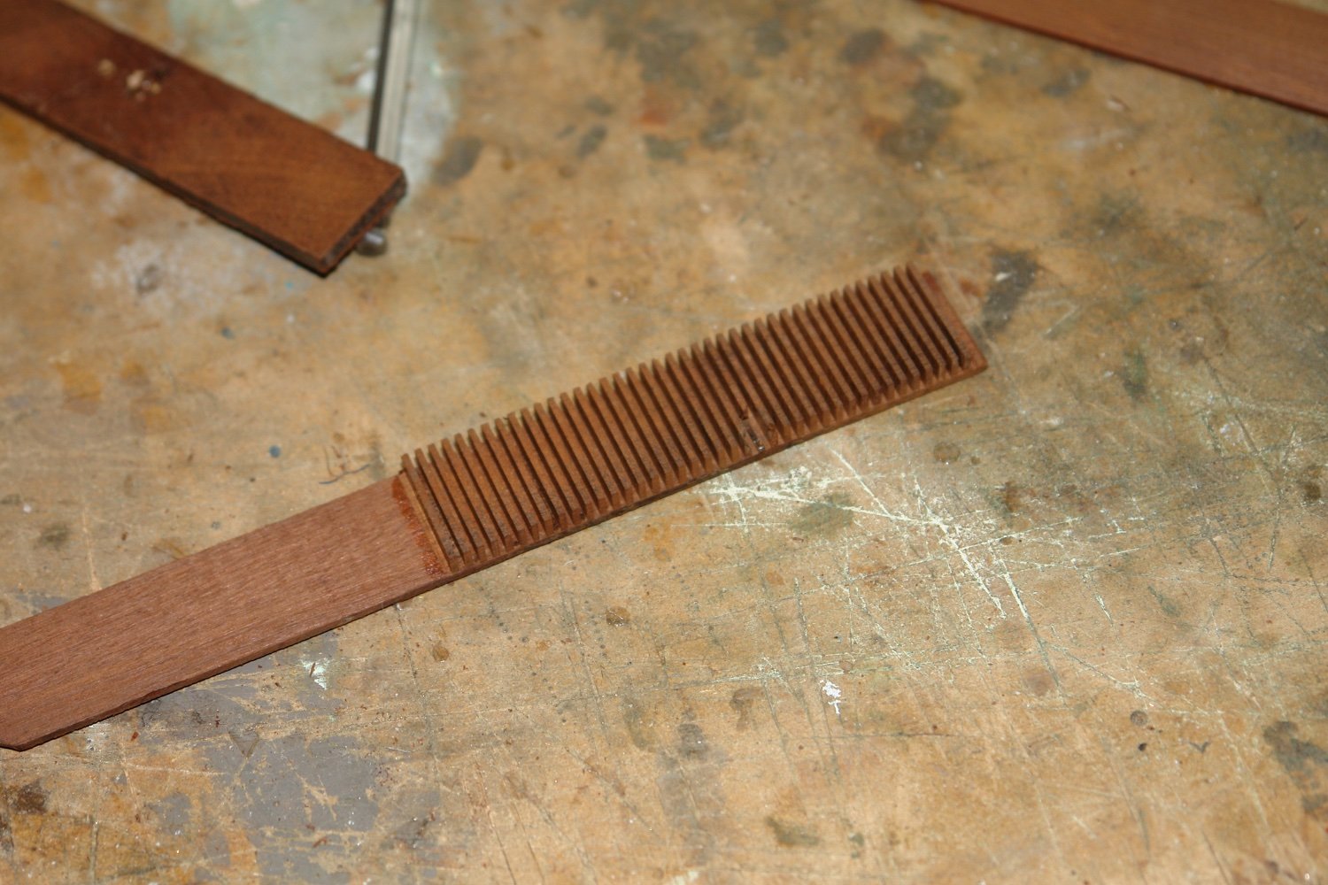
Soon i am going to need a lot of blocks. Repetition isn't one of my favourite activities so I though I would start the block production line and then do a few at a time as needed.
I always read the block making posts of other MSW members with interest, but in the end I come back to what I know. I am therefor repeating the method that I used for Altair with a few slight improvements.
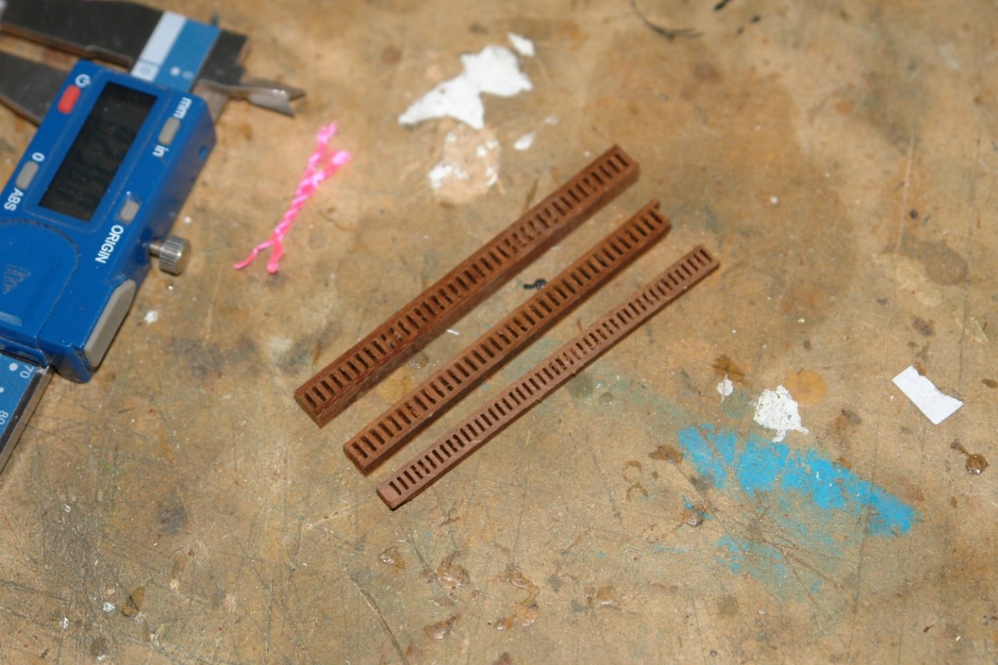
I need 3 sizes of .2" .24" and .28" (5mm 6mm 7mm) overall height.
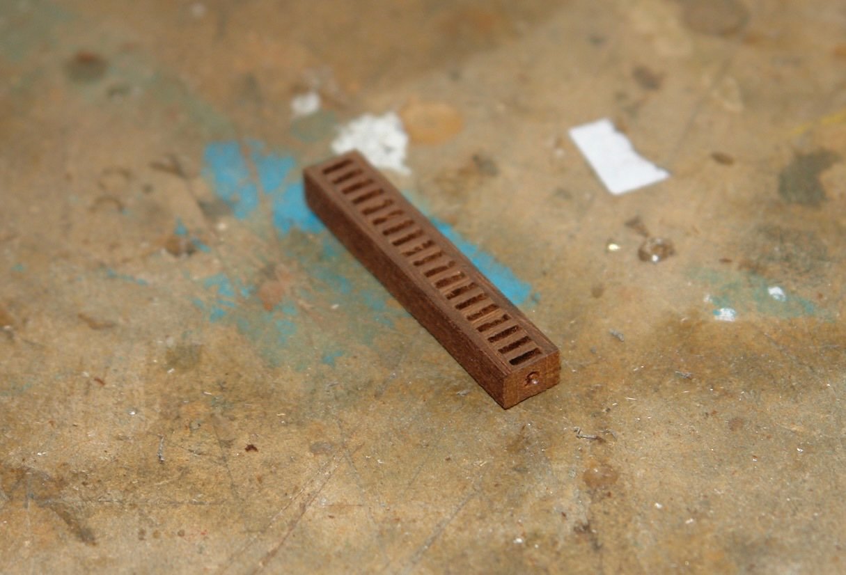
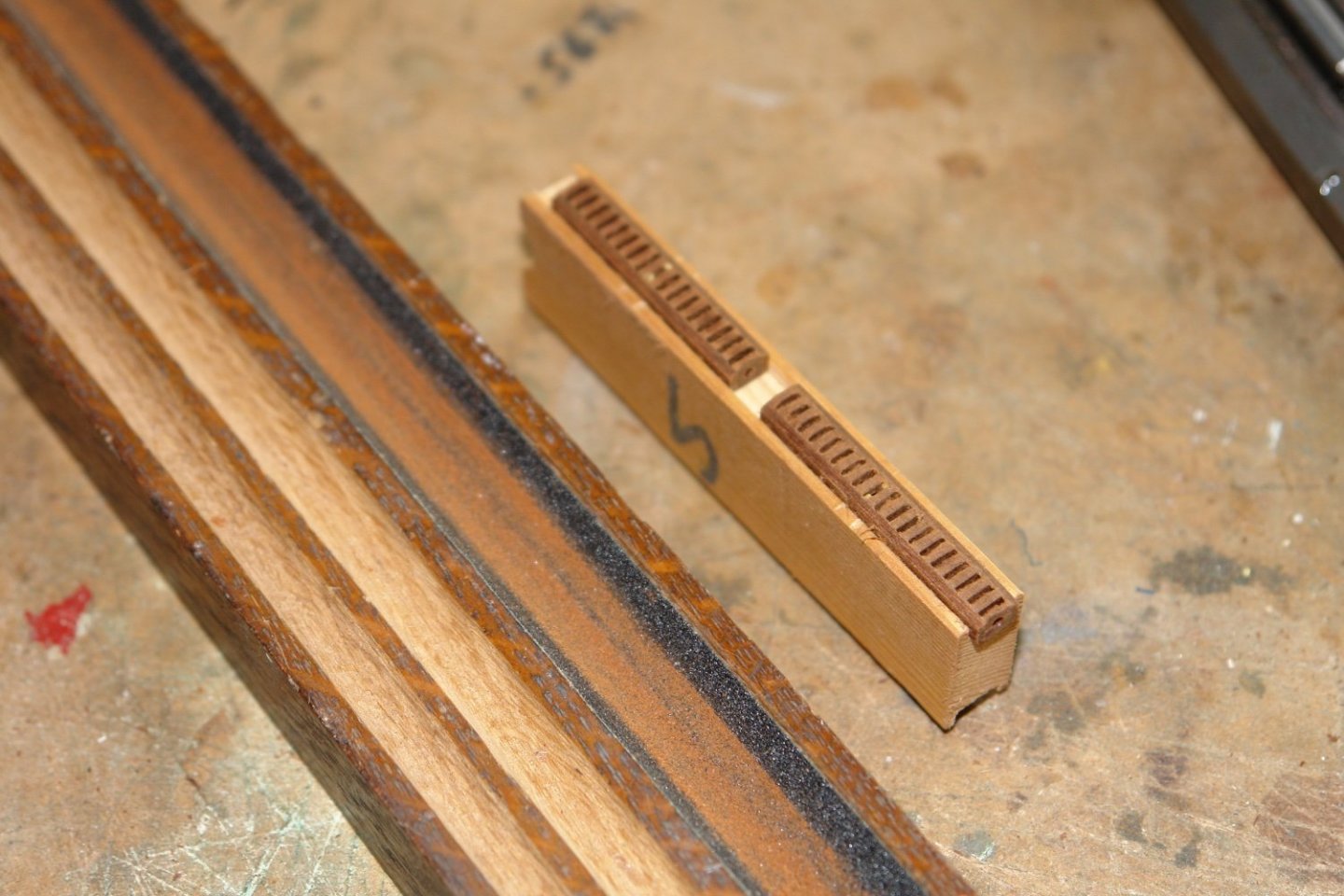
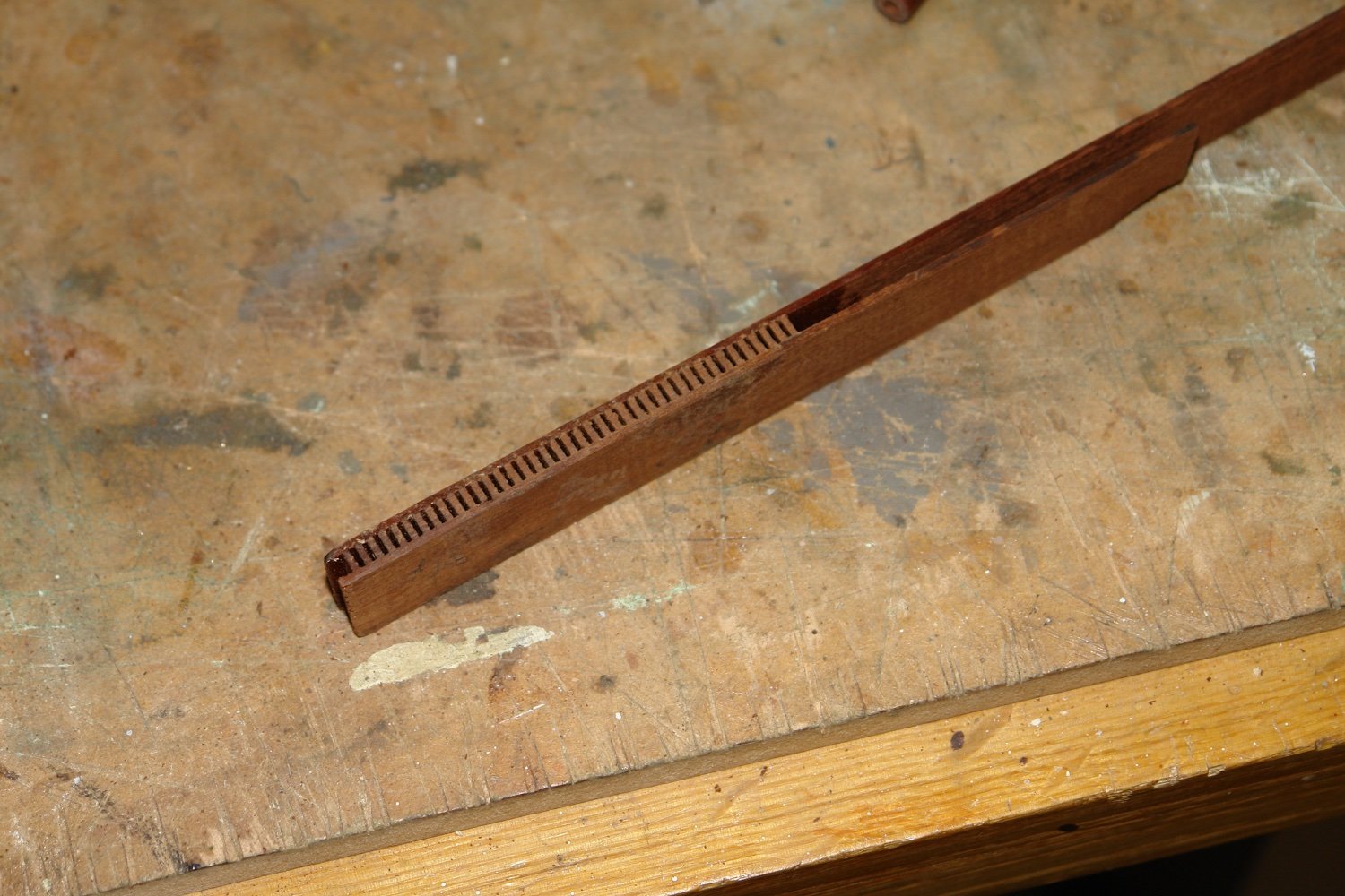
I start with a strip of mahogany and glue on to this a further strip which I accurately slot cut on the table saw.

I then glue on a closing strip.
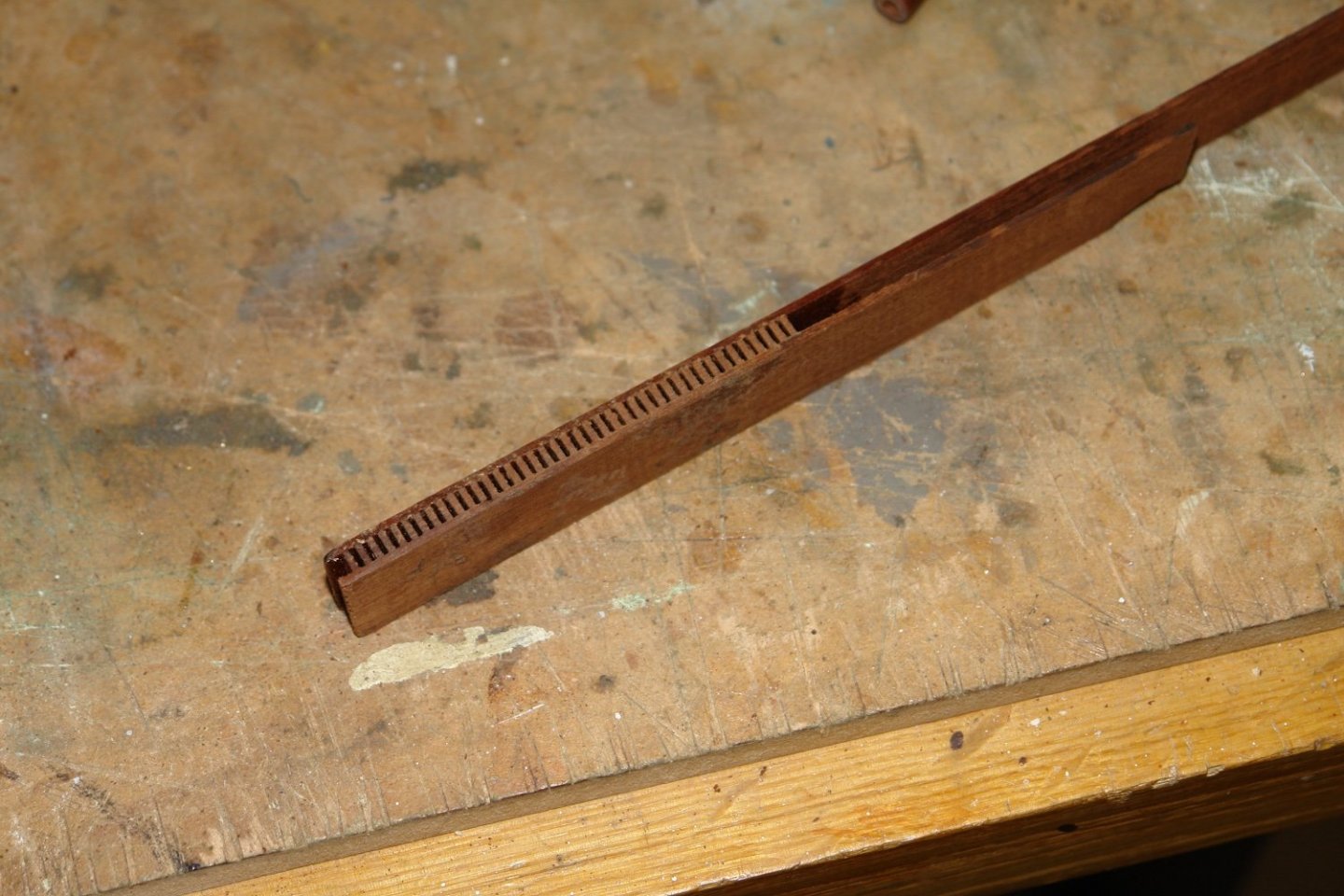
I need 3 of these for the 3 sizes required.
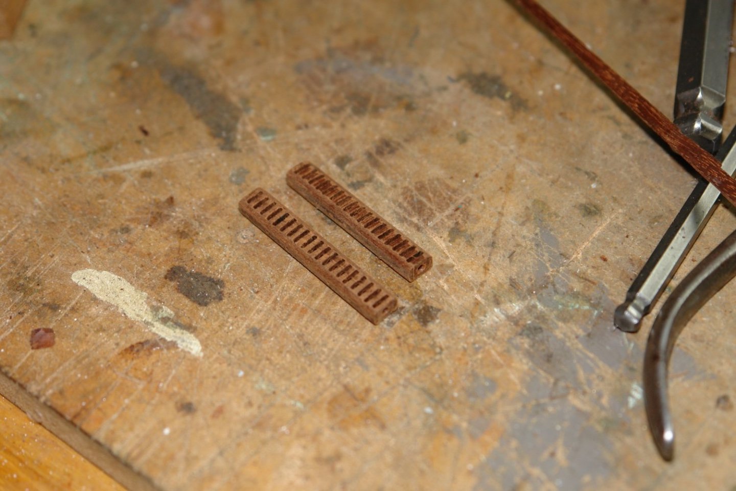
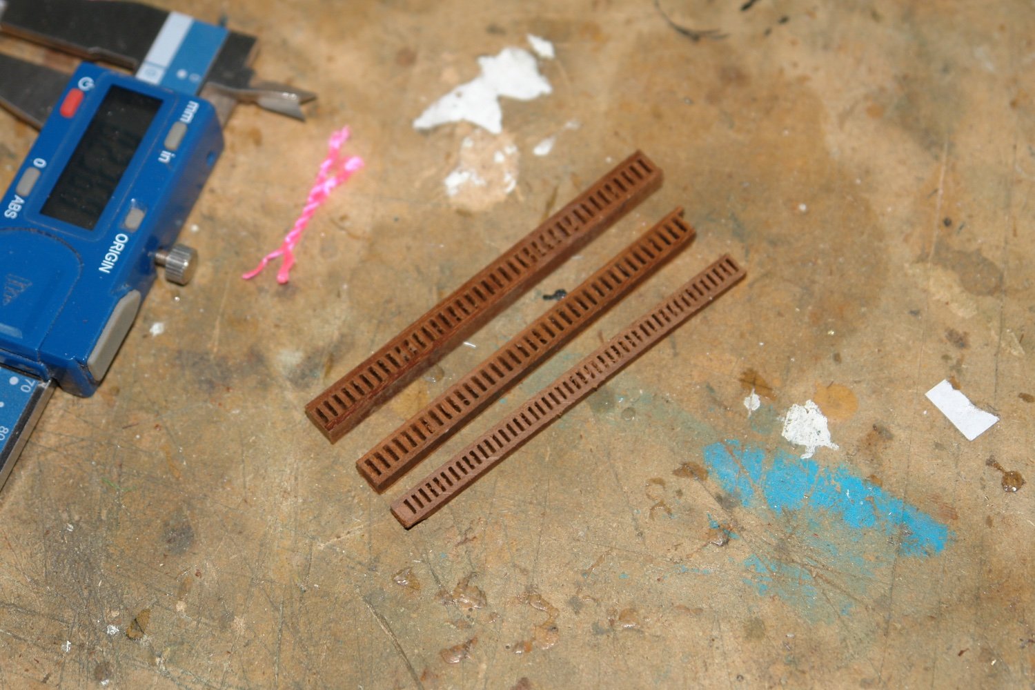
I then slit off strips with the width being equal to the width of the finished block.
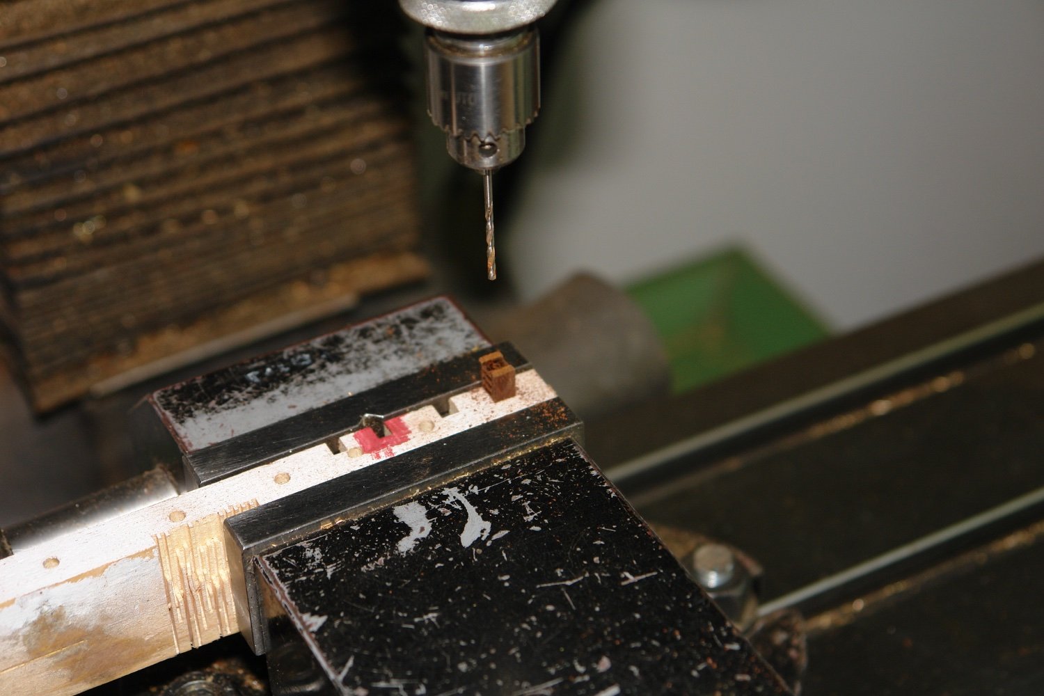
I then need to drill an axial hole. For this I made a holding jig with slots accurately cut to take the strips pictured above.
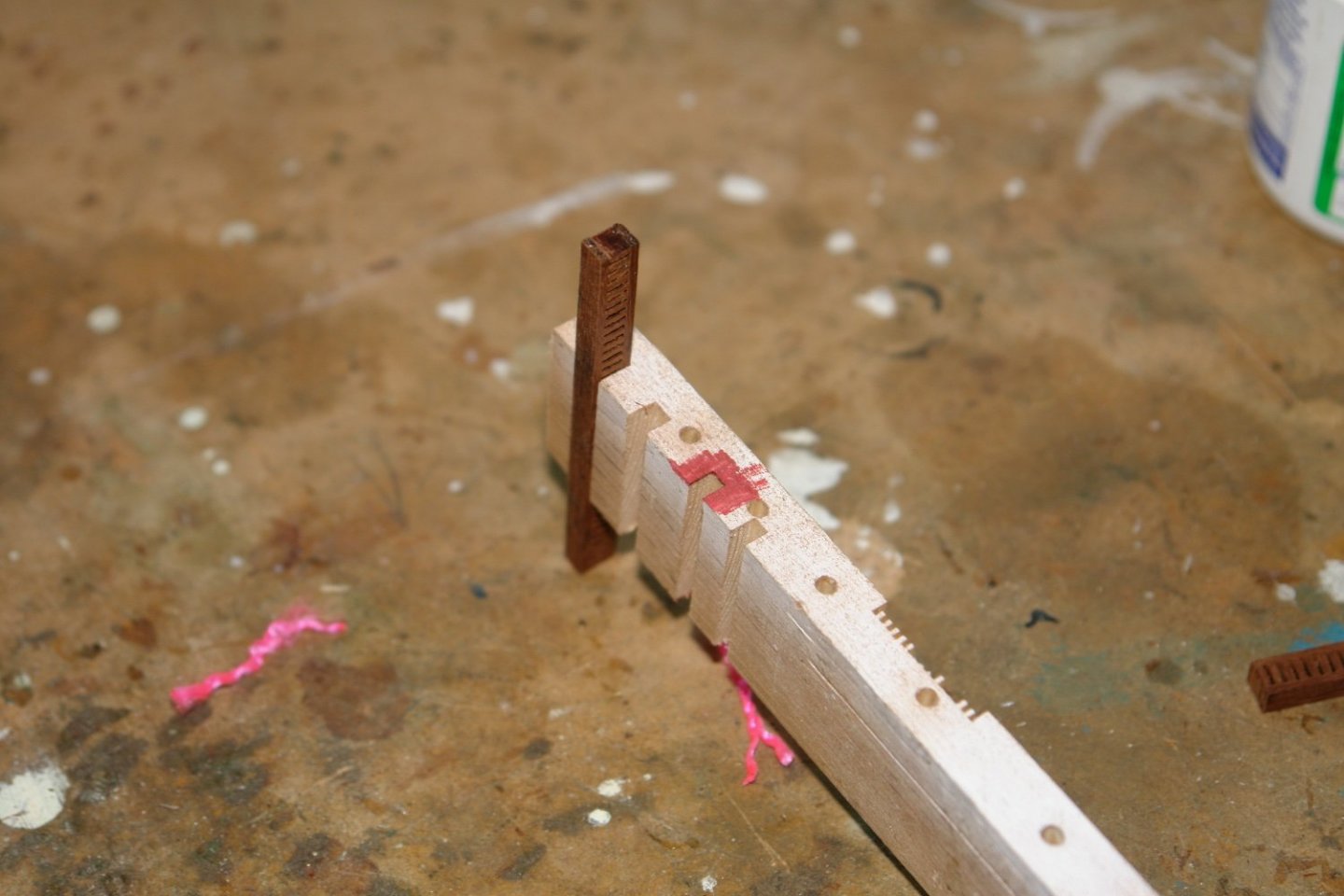
This was fixed with double sided tape to the moveable jaw of the machine vice. This arrangement allowed me to accurately and repeatably drill the axial hole.

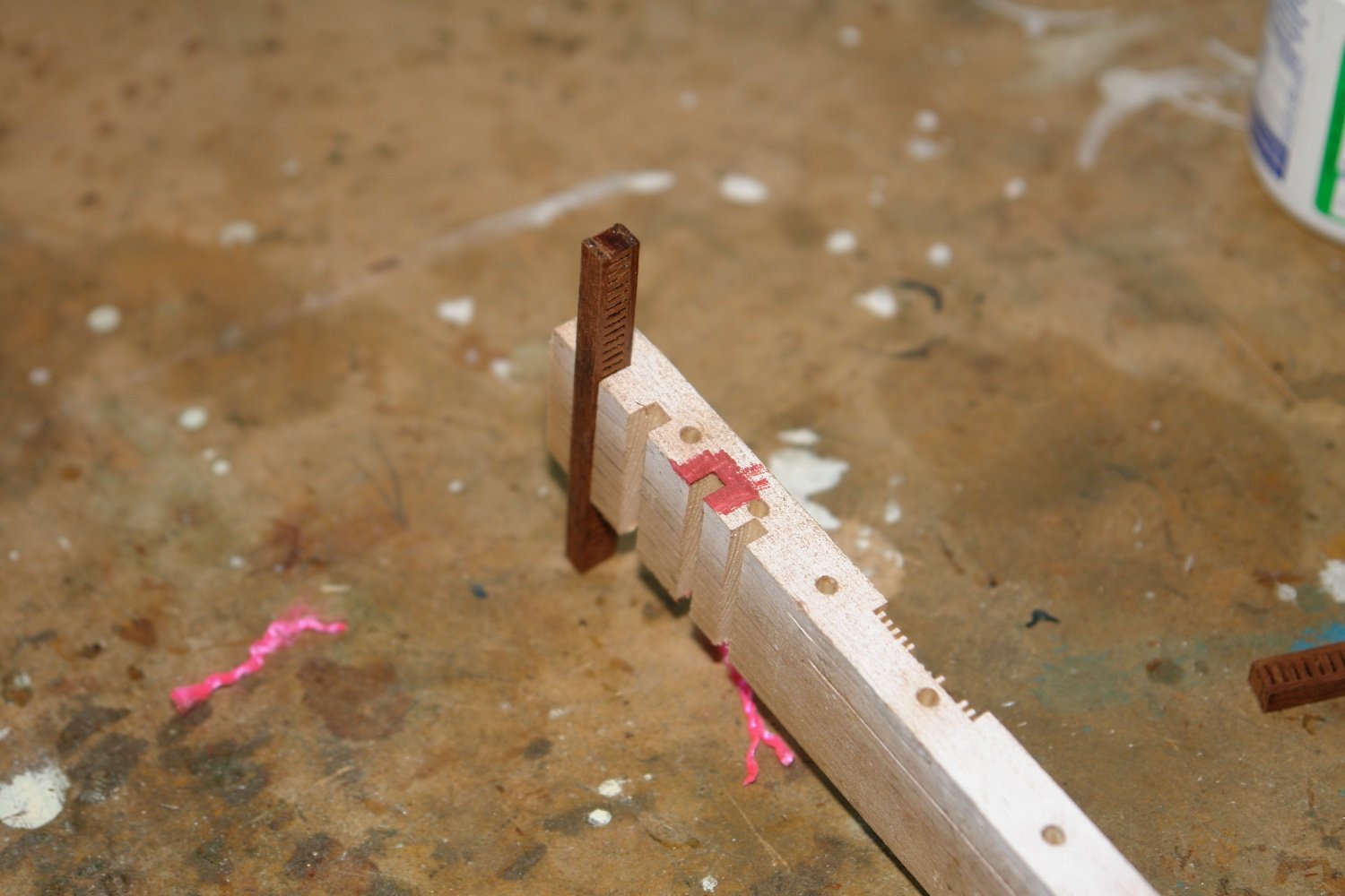
I then made a fixture to hold the strips for sanding. This was just a slot in a piece of wood with 1 mm pins to locate the strips.
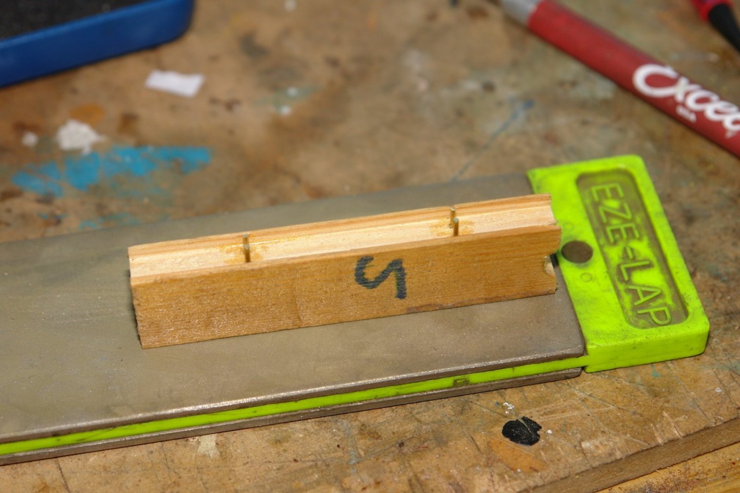
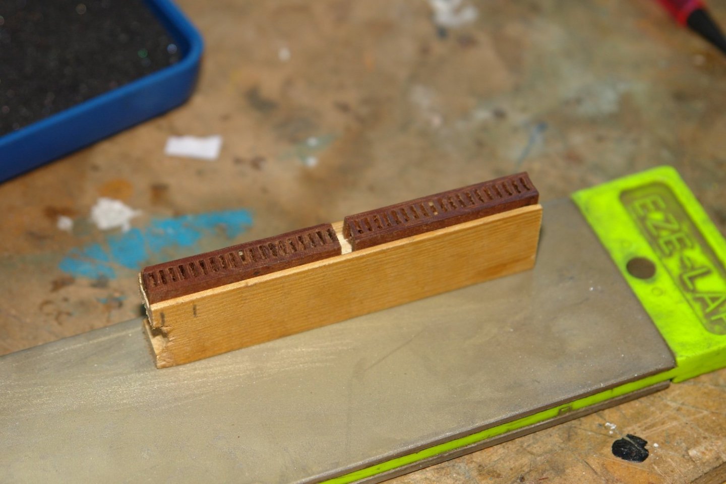
With the strips mounted the edges of the blocks were rounded using emery paper glued into a circular slot.
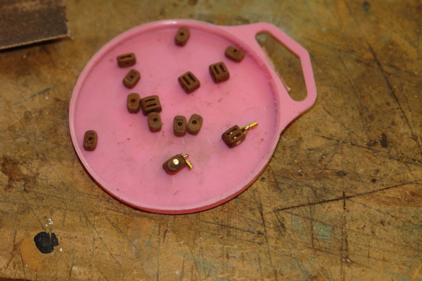
At this stage the strips were moved back to the mill and the 2 ends were drilled in various configurations to take attachment fittings.
From the strips single double or triple blocks can be cut off as required
- FlyingFish, Bedford, Retired guy and 16 others
-
19
-
-
On 2/10/2022 at 12:33 AM, Peter6172 said:
I use a standard pair of cheep Circles pliers (the type that operate like normal pliers not reverse pliers). I file down one of the circular tips to a fine cone with needles files then use a flat file to make sure that there is an even, parallel flat between the two jaws of the pliers.
Peter, I am wondering how the pliers can be soft enough to file down while being strong enough not to bend when being used? Do you harden them? Perhaps you can explain?Ideally the answer would be to buy hardened conical nosed pliers. However I have not yet found any with very small points to the cones. Most available on the web seem to have cones with a minimum diameter of about 1mm, whereas I would agree that 0.5mm is more useful. Does anyone know of conical nosed pliers with very small tip diameters?
-
42 minutes ago, wefalck said:
Your idea of using a sort of micro-wax chuck, as the watchmakers would call it, could in principle work, but by removing it from the collet to release the finished piece, one would loose the concentricity.
Eberhard, yes I was aware of that problem, hence my remark about making all the blanks first.
The larger piece of stock would be mounted and drilled. The blanks would be inserted into the stock and removed without removing it from the chuck thus retaining concentricity. With your equipment i can see why you favour your method. I was just musing on how I would do it with my equipment.
Most of the fun is working out the possibilities - as demonstrated by your thoughts on other options.😊
- mbp521, Keith Black, Roger Pellett and 1 other
-
4
-
12 hours ago, wefalck said:
This, however, would leave you with rounding the head of handle in a different set-up.
Yes I had assumed this but I bow to your superior knowledge of the ability of the .2mm shank to resist the cutting forces. However I have an idea that I might try in an idle moment -
1. Drill a .2 mm hole in a spare piece of larger stock - say 2mm.
2, Turn the .2mm shank to length and turn the handle to nominal diameter and length. Then part off or more probably cut off with a jewellers saw.
3. Either soft solder or glue the .2mm shank into hole bored in the larger stock.
4 Finish turn the handle and then heat to break the bond.
If I were doing many I think I would make all the blanks first, followed by shaping all the handles. Just for fun I might give it a go on my rather large lathe. But not soon as I don’t have .2mm drills.
- druxey, Keith Black, mbp521 and 1 other
-
4
-
Eberhard,
Very tricky turning. Did you consider making the pins the other way round with the handle end towards the chuck. If you didi why did you decided on the method you used?
- BANYAN, druxey, Keith Black and 3 others
-
6
-
The masts are really attractive and very cleanly made. Excellent work.
-
She has quite an attractive rear, do you know if it severed a particular purpose?
-
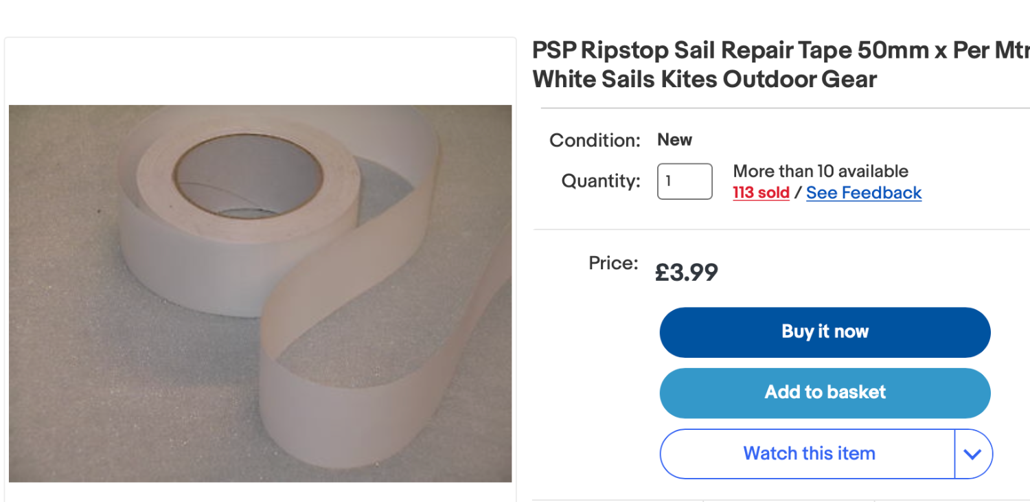
2 hours ago, Jond said:
take some silkspan and try to cover the hatches as they would have been canvassed while sailing.
Jon - I find that for jobs like this rip stop tape works really well. Being self adhesive it is easy to work with and it take colour really well - either from acrylic paint or even permanent markers. I find painting before application is easier as it produces really clean edges. Being a fabric tape it retains some texture even when painted giving it a realistic canvas effect.

-
2 hours ago, Roger Pellett said:
In neither case did we use the double sheet/ guy arrangement
Roger - agreed I have never used the Lazy Guy arrangement. For the record Germania will be rigged with the beak facing upward.
- Roger Pellett, mtaylor and Keith Black
-
3
-
1 hour ago, Veszett Roka said:
Anyway, i found references that spiboom used with upwards looking latch (jaws up) position too, but i would avoid this on my boat for sure.
Veszett,
I think I am back where I started and that is upward and downward facing both have advantages and disadvantages.
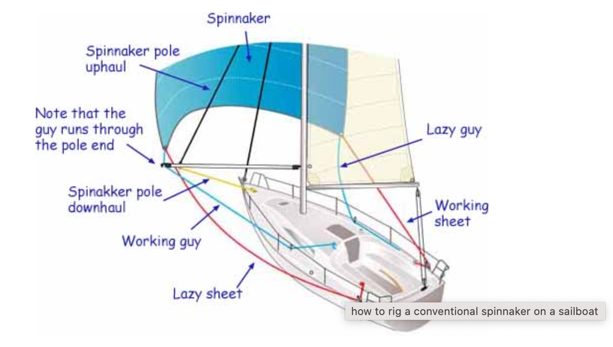
This is also on the net under "how to rig a spinnaker" and shows the jaws facing downward.
- Veszett Roka, JOUFF, Keith Black and 2 others
-
5
-
I thought i had better look up what the internet says about the orientation of the spinnaker pole beak:-
Whisker poles should be flown with the jaws facing down. When taking down a whisker pole, the jib sheet usually wants to drop down-and-out of the end fitting. Spinnaker poles are flown jaws facing up, as the spinnaker sheets usually want to lift up-and-out of the end fitting.
- FriedClams, mtaylor, Keith Black and 1 other
-
4


Glory of the Seas 1869 by rwiederrich - FINISHED - 1/96 - medium clipper
in - Build logs for subjects built 1851 - 1900
Posted
Beautifully done.