


KeithAug
-
Posts
3,384 -
Joined
-
Last visited
Content Type
Profiles
Forums
Gallery
Events
Posts posted by KeithAug
-
-
Almost over before it started, looks lovely.
- Mirabell61 and mtaylor
-
 2
2
-
-
-
Nils, CPDDET, John, Steve and Pat, thank you for commenting.
Its been pretty warm here - touching 33c Monday and due to get hotter. Not warm by what many of you see but certainly unpleasant enough here.
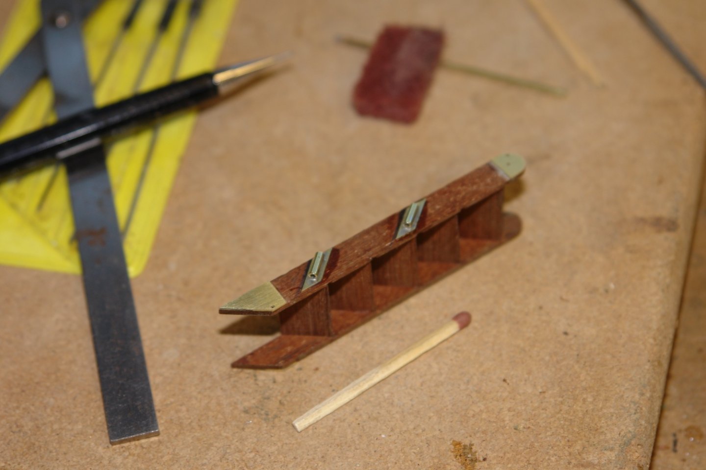
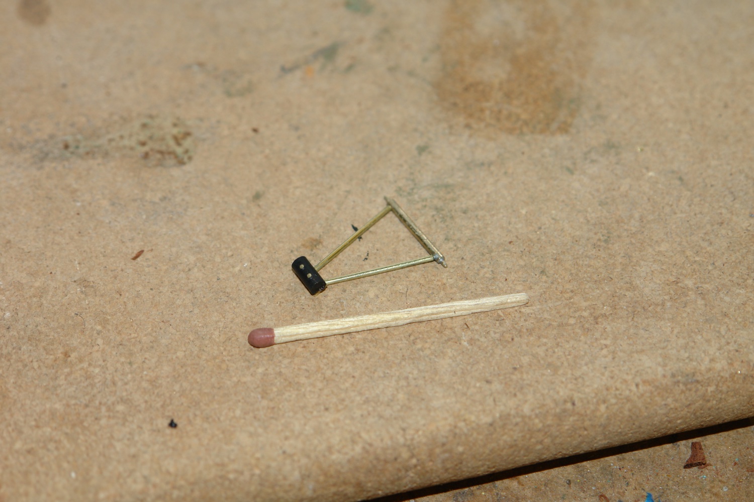
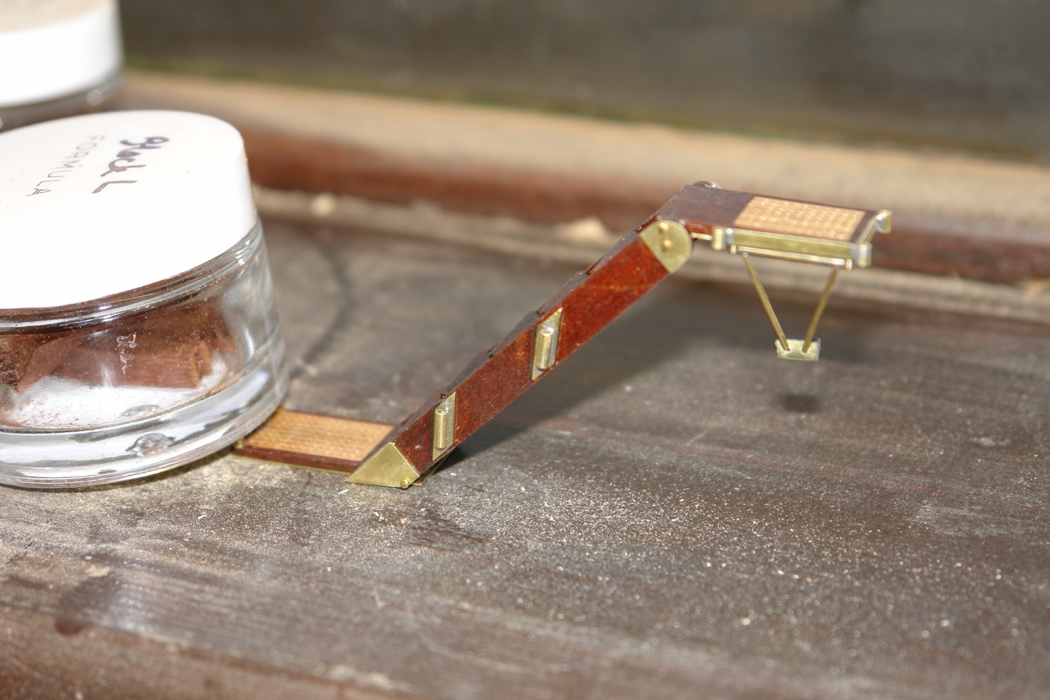
I finished the steps by making the support piece. It is a triangular frame pivoted at the wide end with a rubber buffer on the pointy bit.

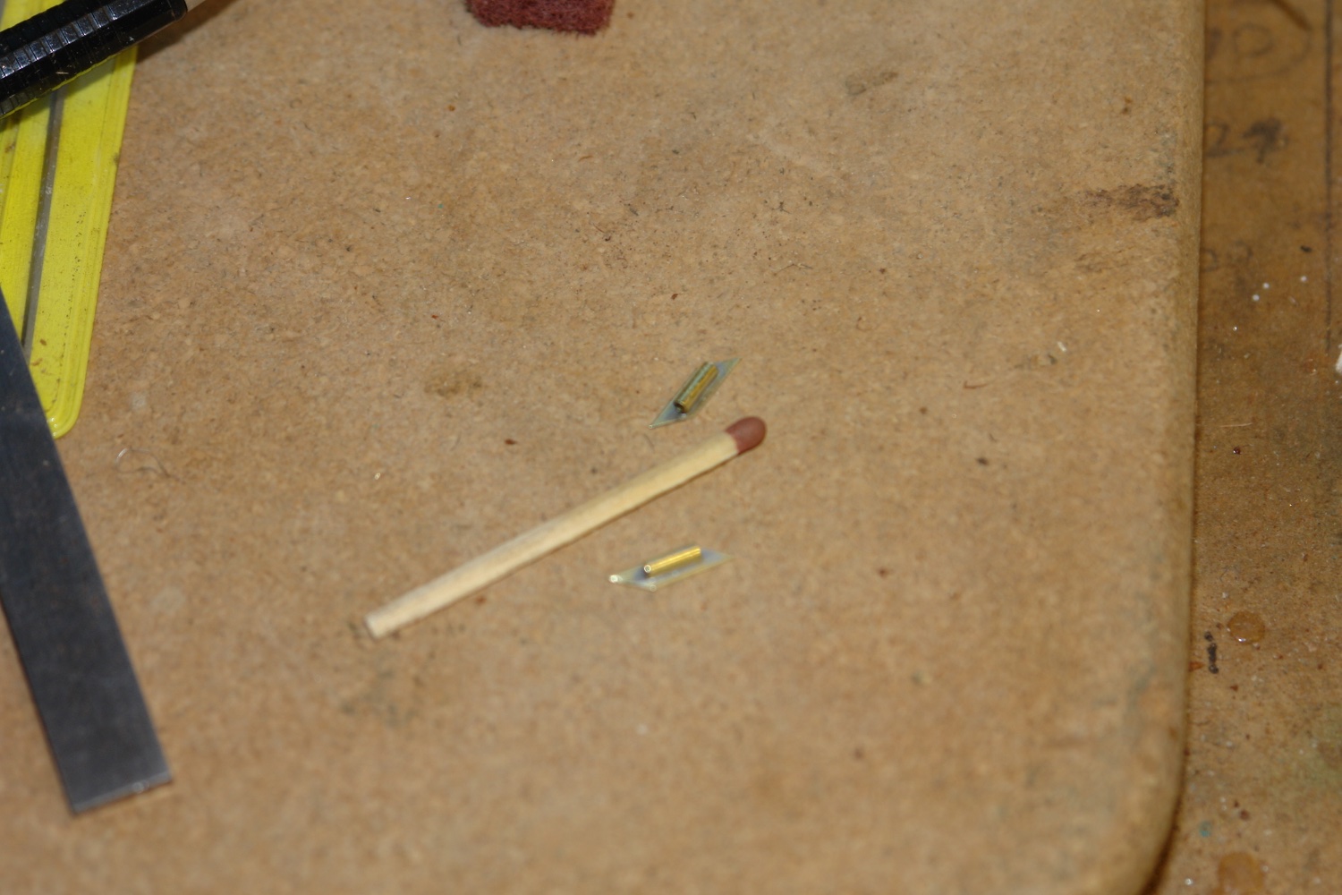
It swings into place on 2 hinge pins (next two the match head)

These pins mount on to the frame on to the underside of the top platform.
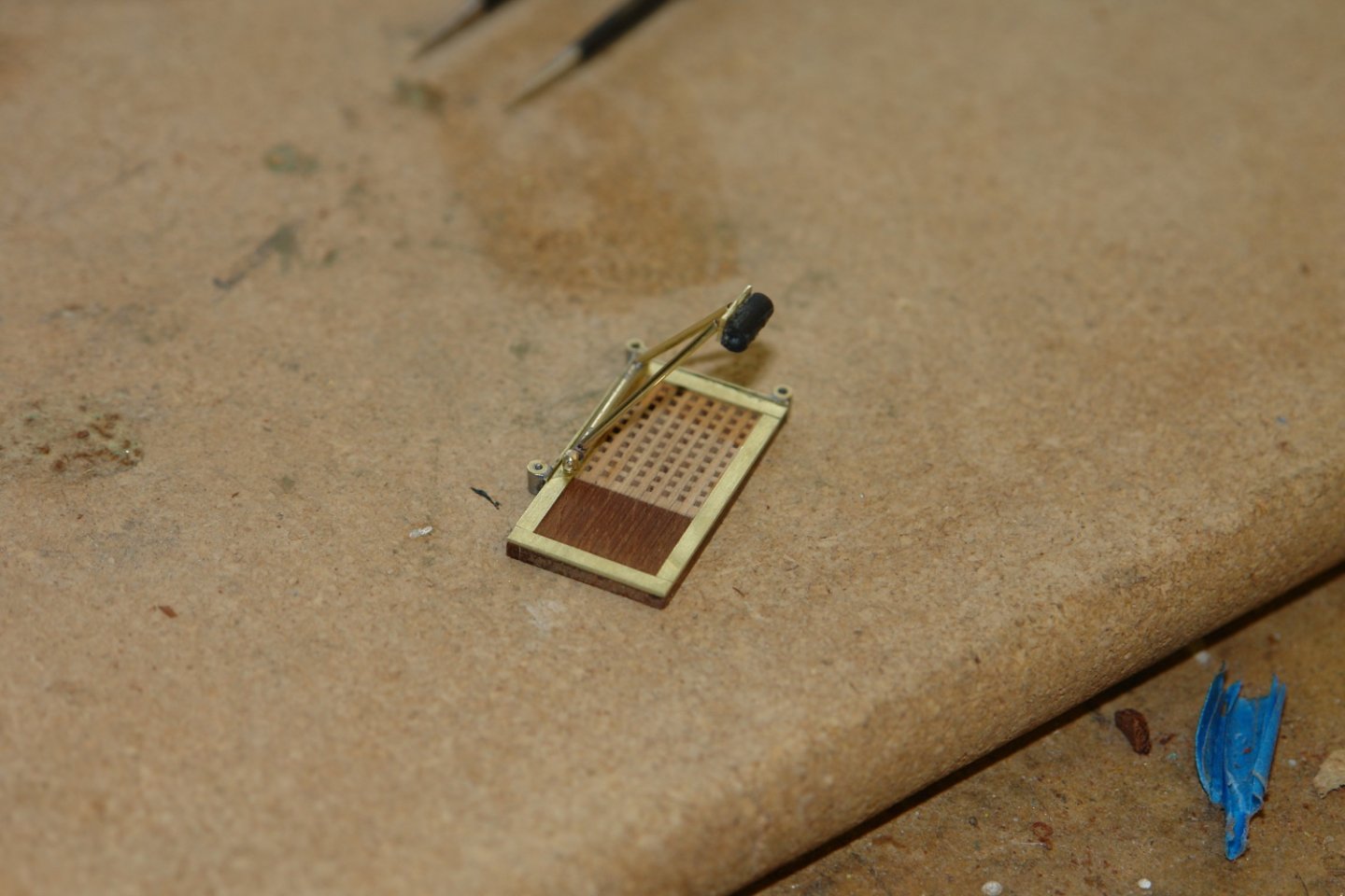
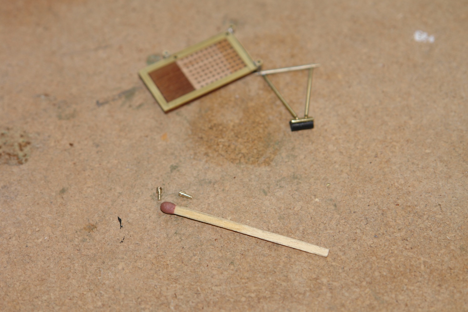
The upper and lower platforms were attached to the steps by pivot pins. Here the steps are photographed in the working position.
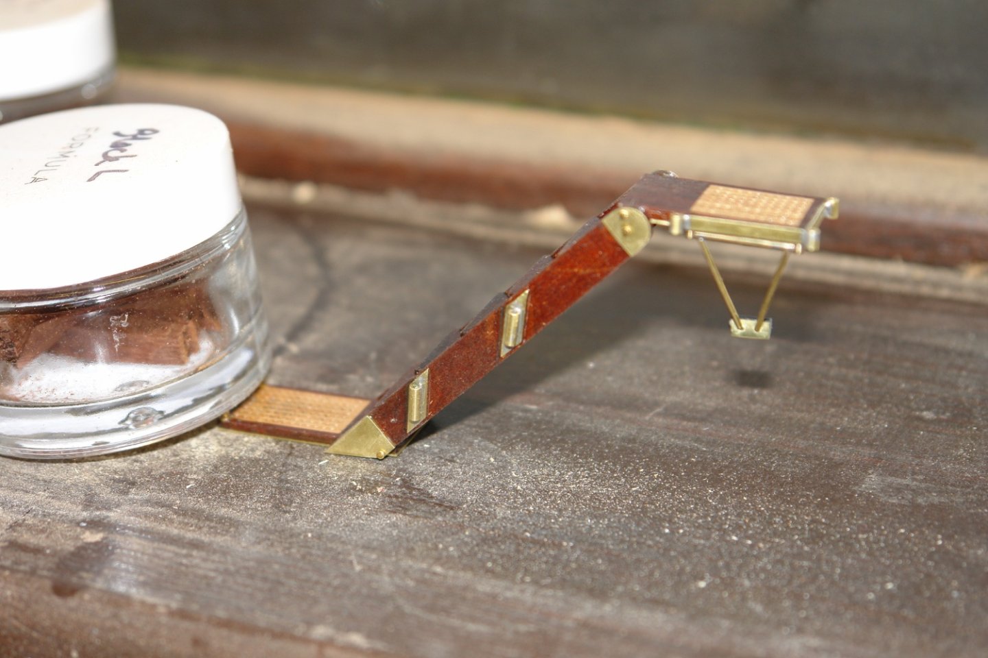
The steps are folded flat for stowage on the rail.

- FriedClams, Siggi52, GrandpaPhil and 16 others
-
15
-
 4
4
-
Eberhard, sorry to hear your covid news. It is starting to feel like my wife and I will be the last ones standing. No doubt our turn will come soon. The planking looks excellent, very impressive.
- bruce d, Keith Black, mtaylor and 2 others
-
5
-
Pat, Mark, Keith, Greg, Brian, Andy - thank you all for your kind comments.
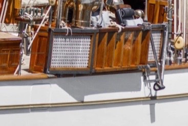
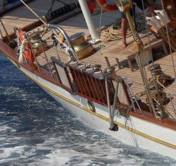
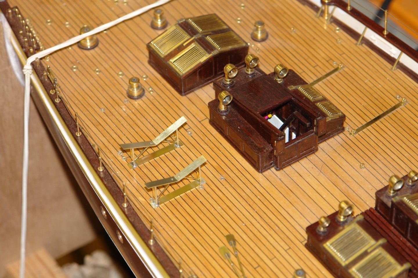
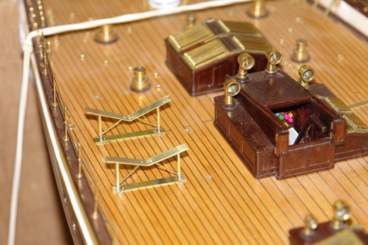
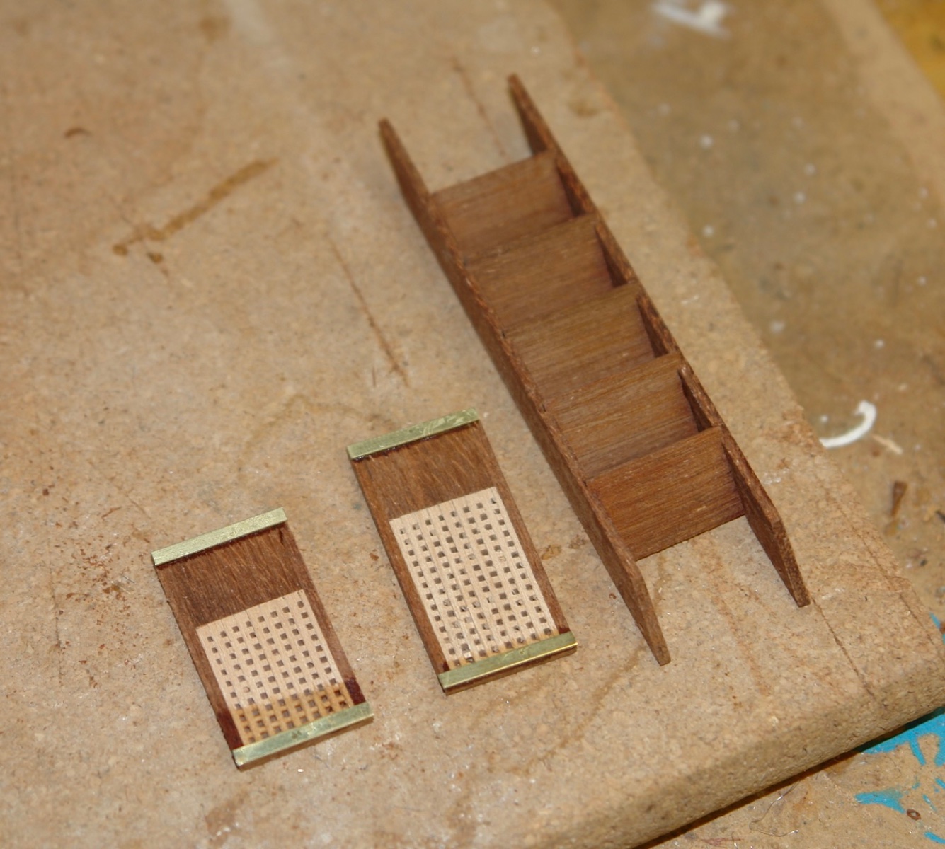
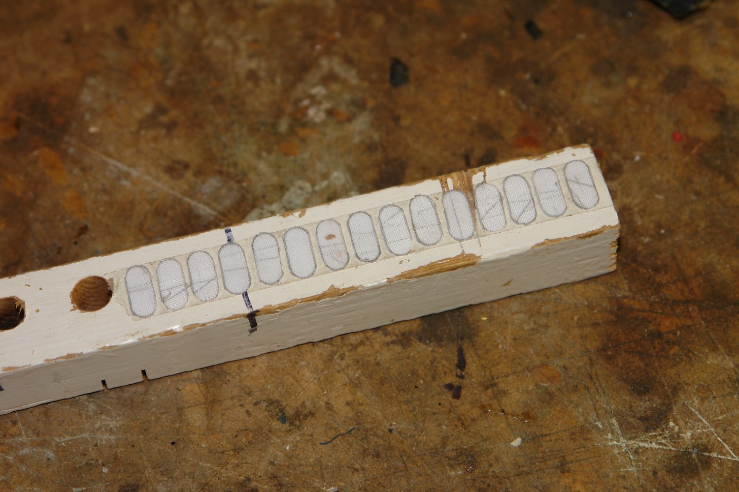
The weather has been good here for a couple of weeks which means most of my time has been spent in the garden. I did find a bit of time for the boat and concentrated on the boarding steps. These fold up to store on the starboard rail.
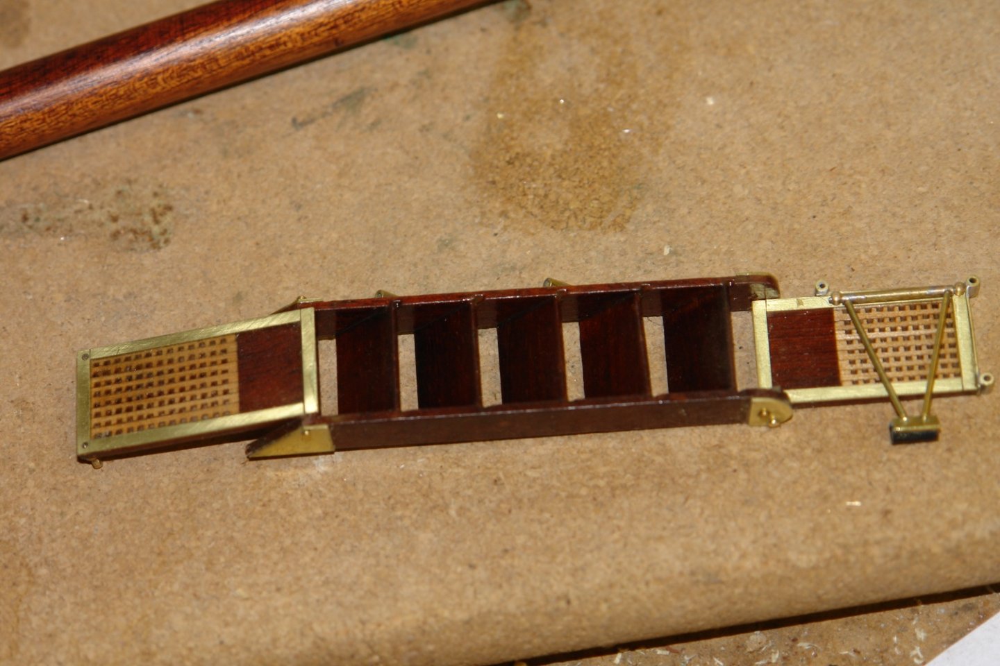
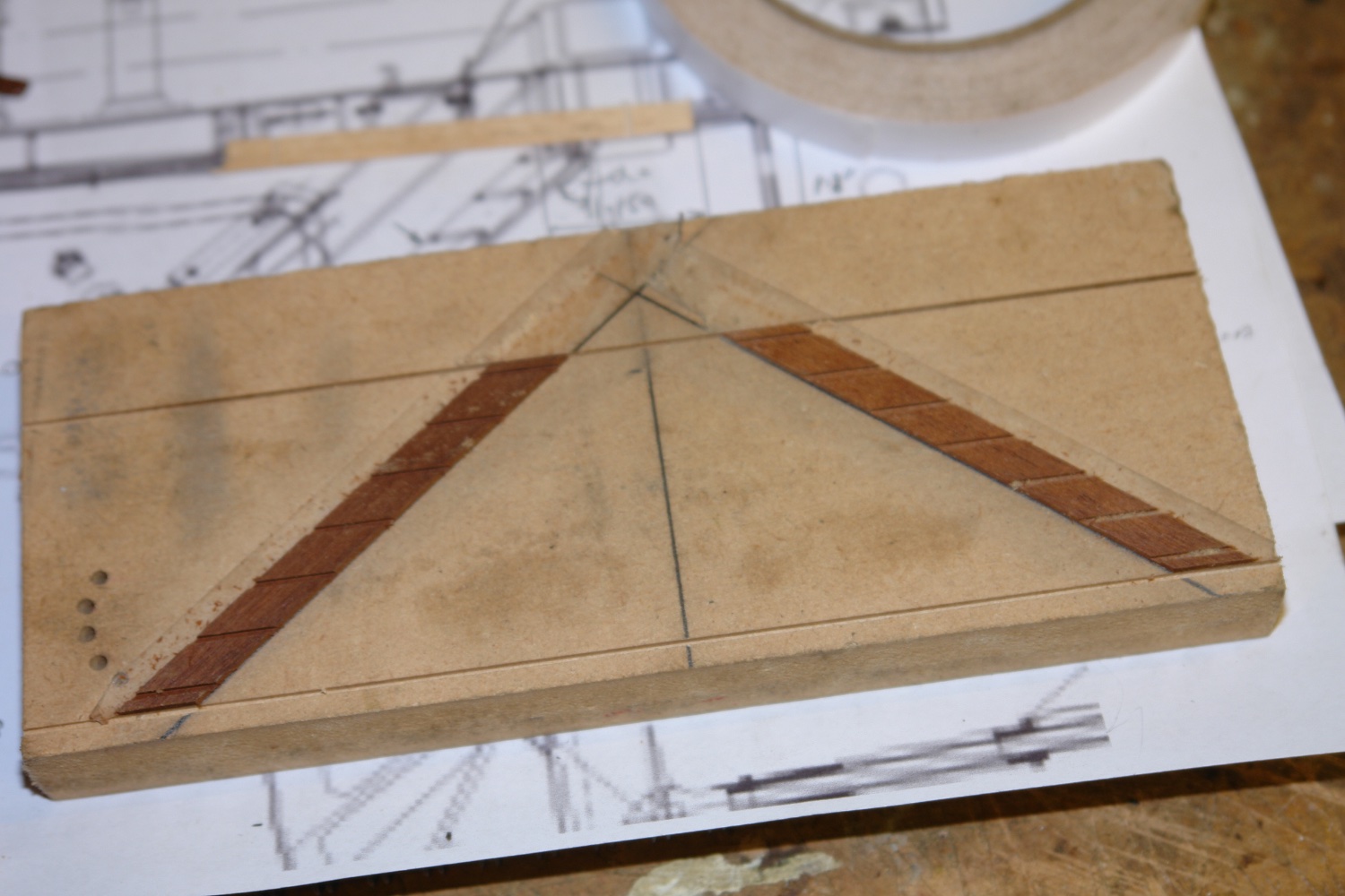
I started by marking out the angle of the steps on a sheet of MDF before attaching mahogany strips to this with double sided tape. The strips were then slotted to half their depth using the table saw. The slots were .040" wide by .030" deep.
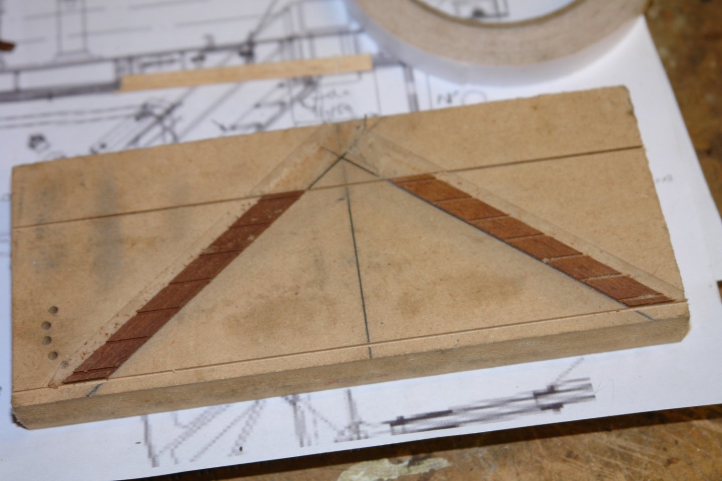
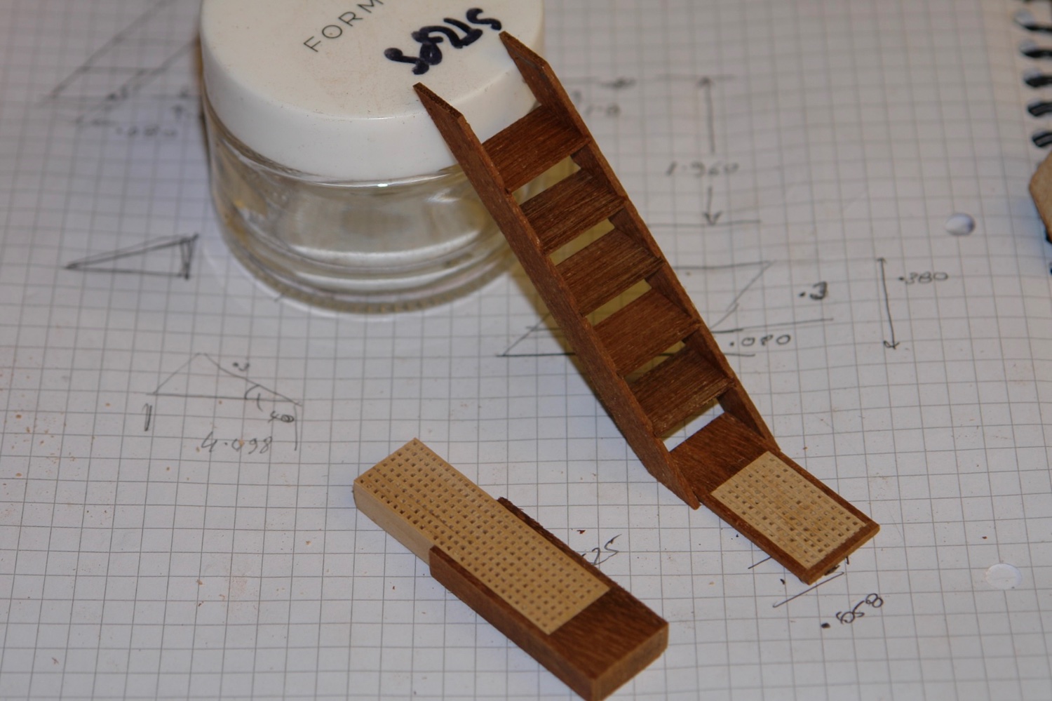
The strips were then removed and 1mm thick steps were cut. The sides and steps were then glued together.
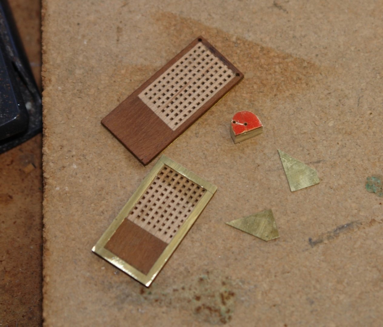
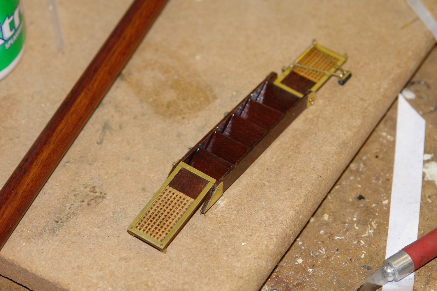
The bottom and top steps are extended to form a platform and both are hinged to fold flat. These upper and lower steps include a grating section and fortunately I had grating material available from earlier in the build.
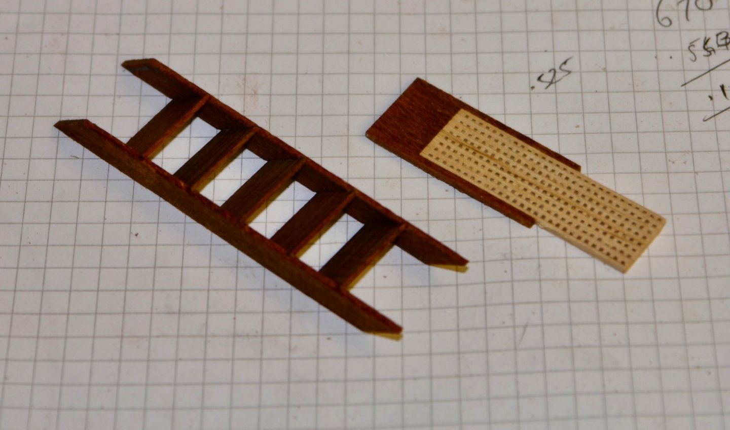

The upper and lower steps are heavily braced with metal strips.

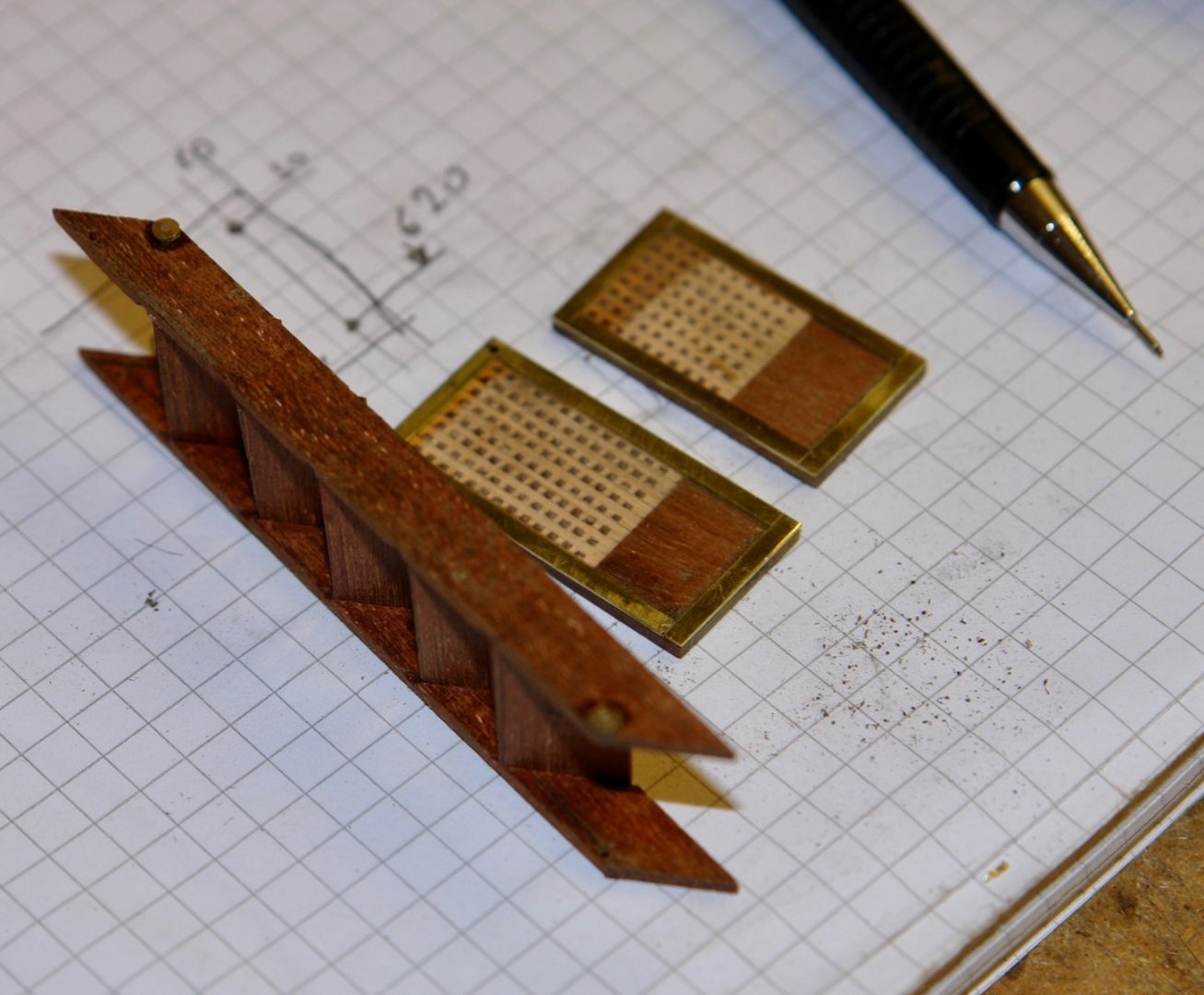
The step sides are also reinforced at the ends with metal plates. These reinforce the pivot points.
The top platform has mounting holes for the demountable stanchions. These were made from tube and soldered in place.
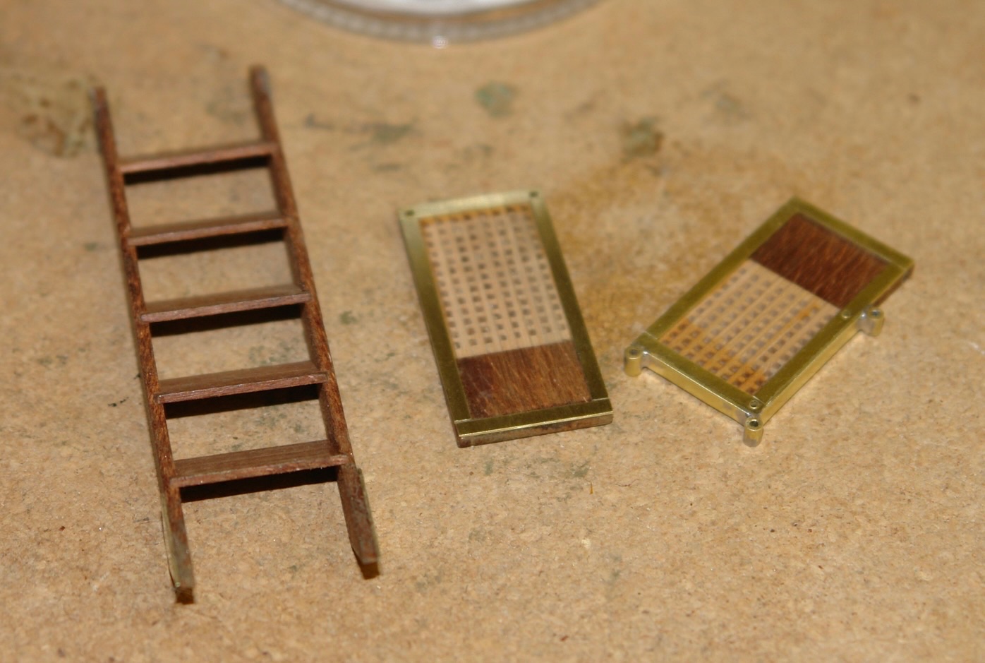
One side of the steps has mounting brackets for more demountable stanchions.

I now need to make the support frame that braces the upper platform agains the hull.
-
Well that was an extensive and excellent update Brian. Why did you decide not to use brass for the ships bell - not withstanding the question the bell looks excellent.
- Canute, Keith Black, FriedClams and 2 others
-
4
-
 1
1
-
On 7/5/2022 at 8:47 AM, Mirabell61 said:
ordered a CANON Pixma TS 3451
Nils - I bought a Canon TS8050 several years ago and found it to be quite temperamental, possibly due to my incompetence. I hope you have more success. Good start on the sails - as you say the printing looks excellent.
- mtaylor and Mirabell61
-
2
-
32 minutes ago, von_bednar said:
Another hiccup that really kept me from posting update was that the middle deck developed quite a curve.
Fixing mistakes is all part of the fun, although it is interesting to note that 3D printed stuff can be porous. A good learning point to share.
- Canute, Keith Black, thibaultron and 2 others
-
5
-
-
-
Lovely - do you know why it had a green bottom?
- Valeriy V, mtaylor and Keith Black
-
2
-
1
-
-
9 hours ago, dvm27 said:
my bedroom set is of a similarly stained dark wood and it shows every spec
Greg - thank you - yes dust is a problem. Germania will require a good clean when finished - and more cleaning thereafter. As for the bedroom the best bet is employ a cleaner or remove glasses before entering. (Anti-static polish helps a little).
- druxey, mtaylor, Keith Black and 1 other
-
4
-
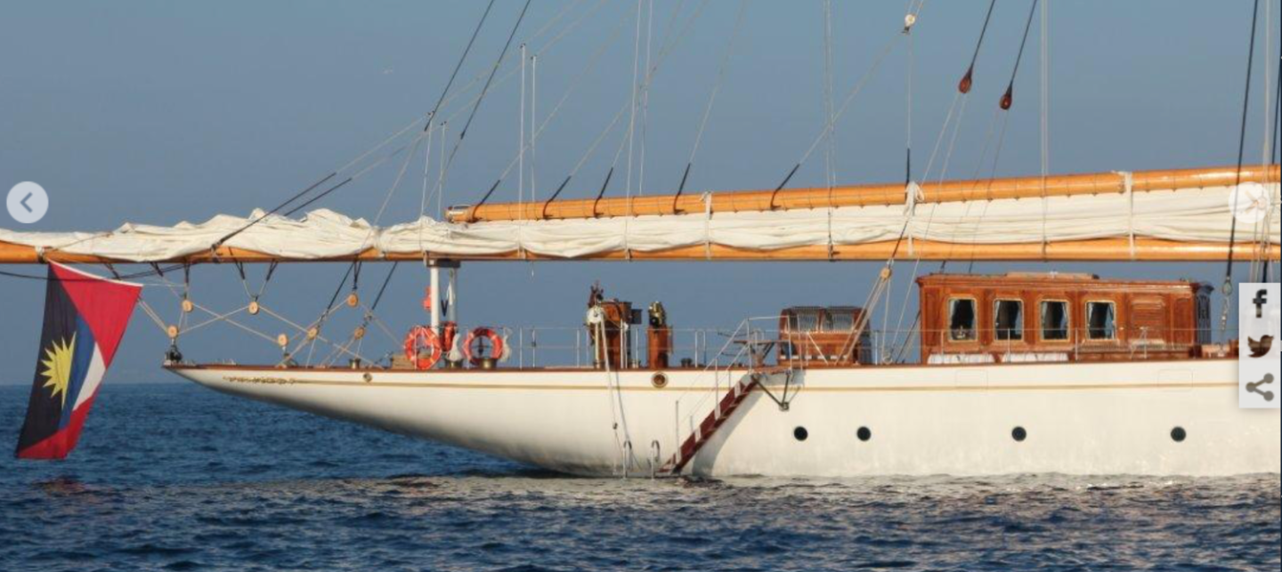
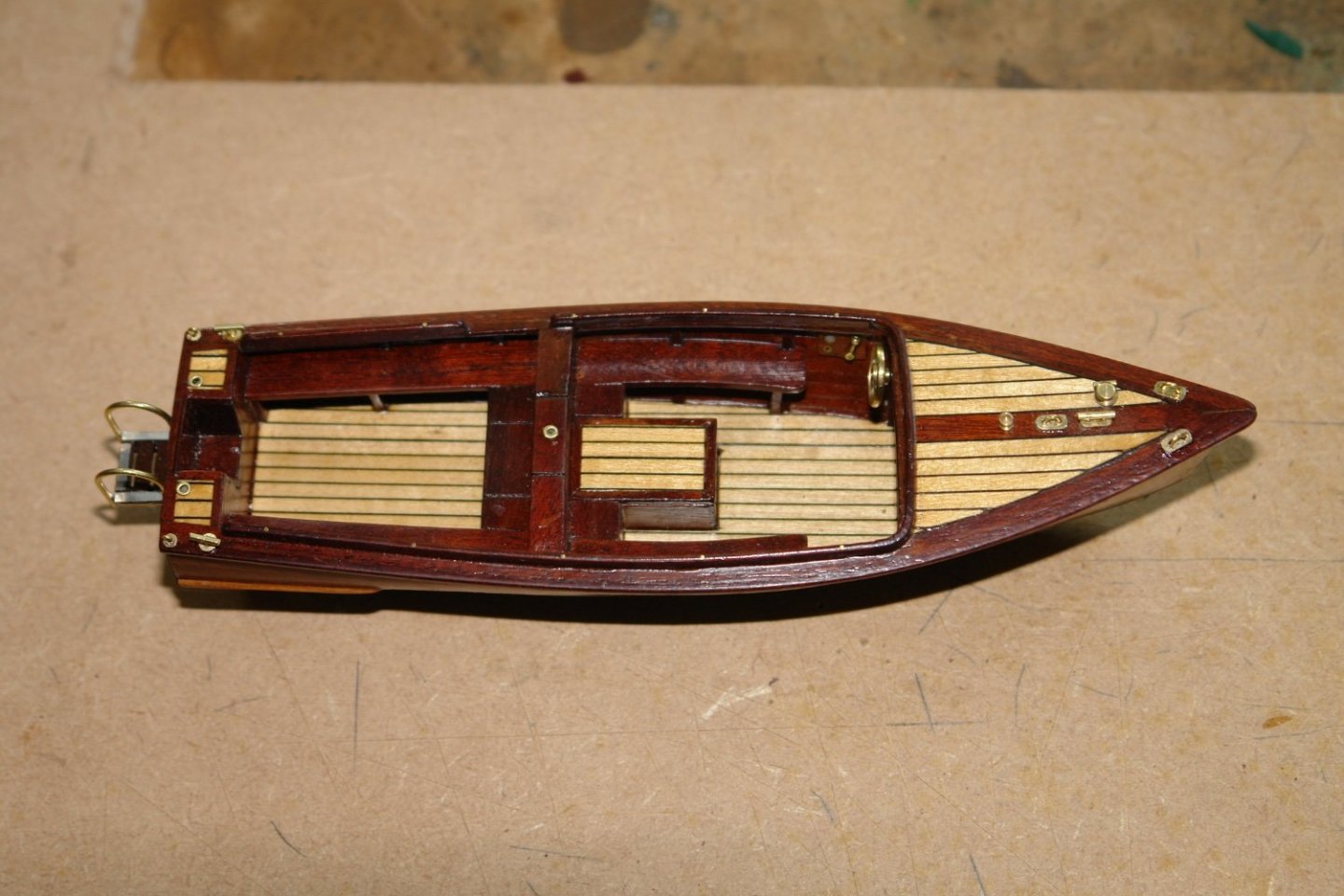
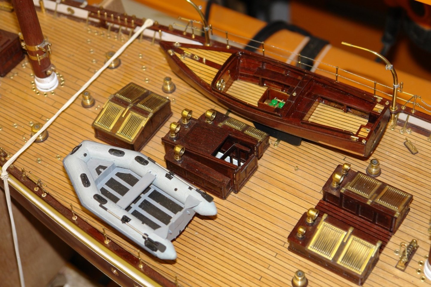
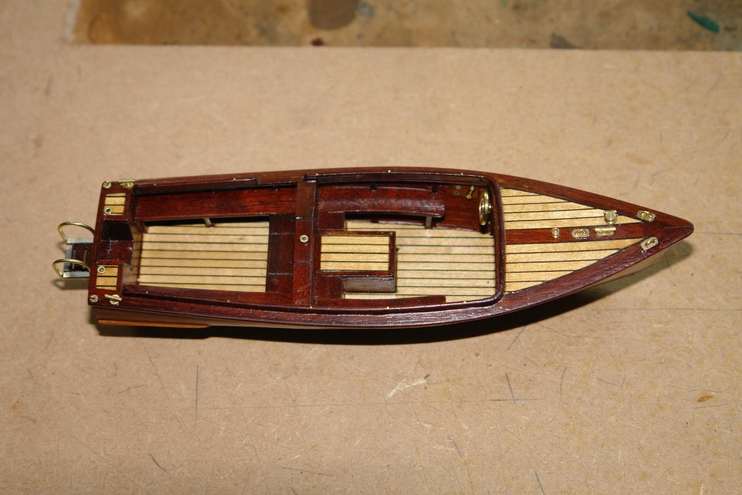
If you recall I hadn't finished the aft "swimming step on the launch". I made the bits a few weeks ago so it was a quick assembly job.
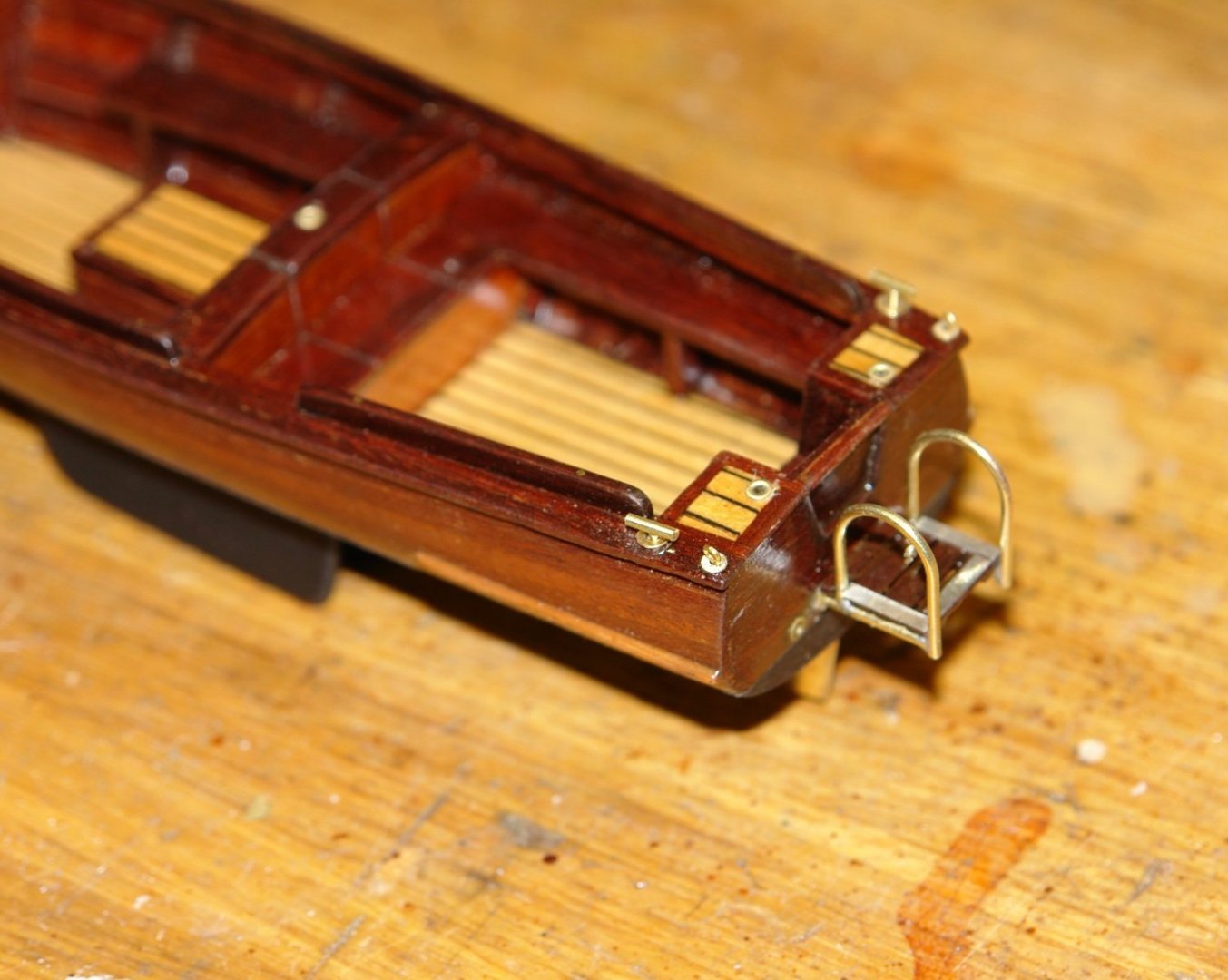
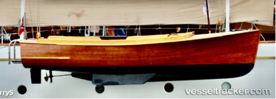
The real thing.
I took a few liberties with the deck wood (as well as the engine and wheel - as mentioned previously).
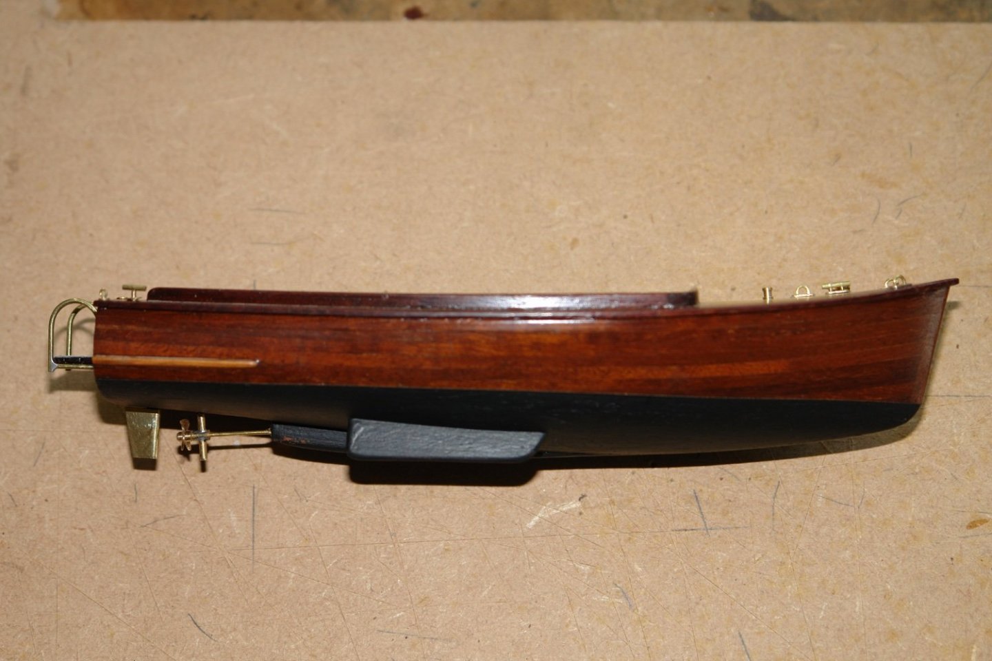
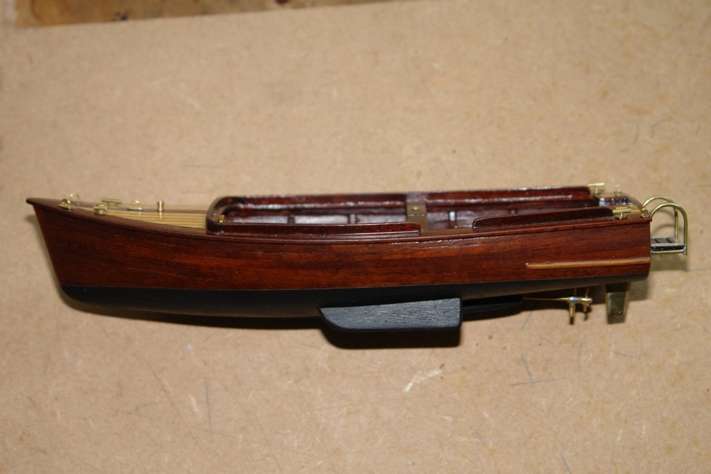
I still need to do the lashings and a mooring lines.
-
17 hours ago, mbp521 said:
My apologies for being way late to the party on this
No apologies needed Brian - I'm glad you made it before the end.
Eberhard, Chris, Druey, Greg, Pat, John, Bean and Nils - thank you all for visiting and leaving comments. Thanks to everyone for the likes and visits.
- mtaylor and Mirabell61
-
2
-
2 hours ago, ccoyle said:
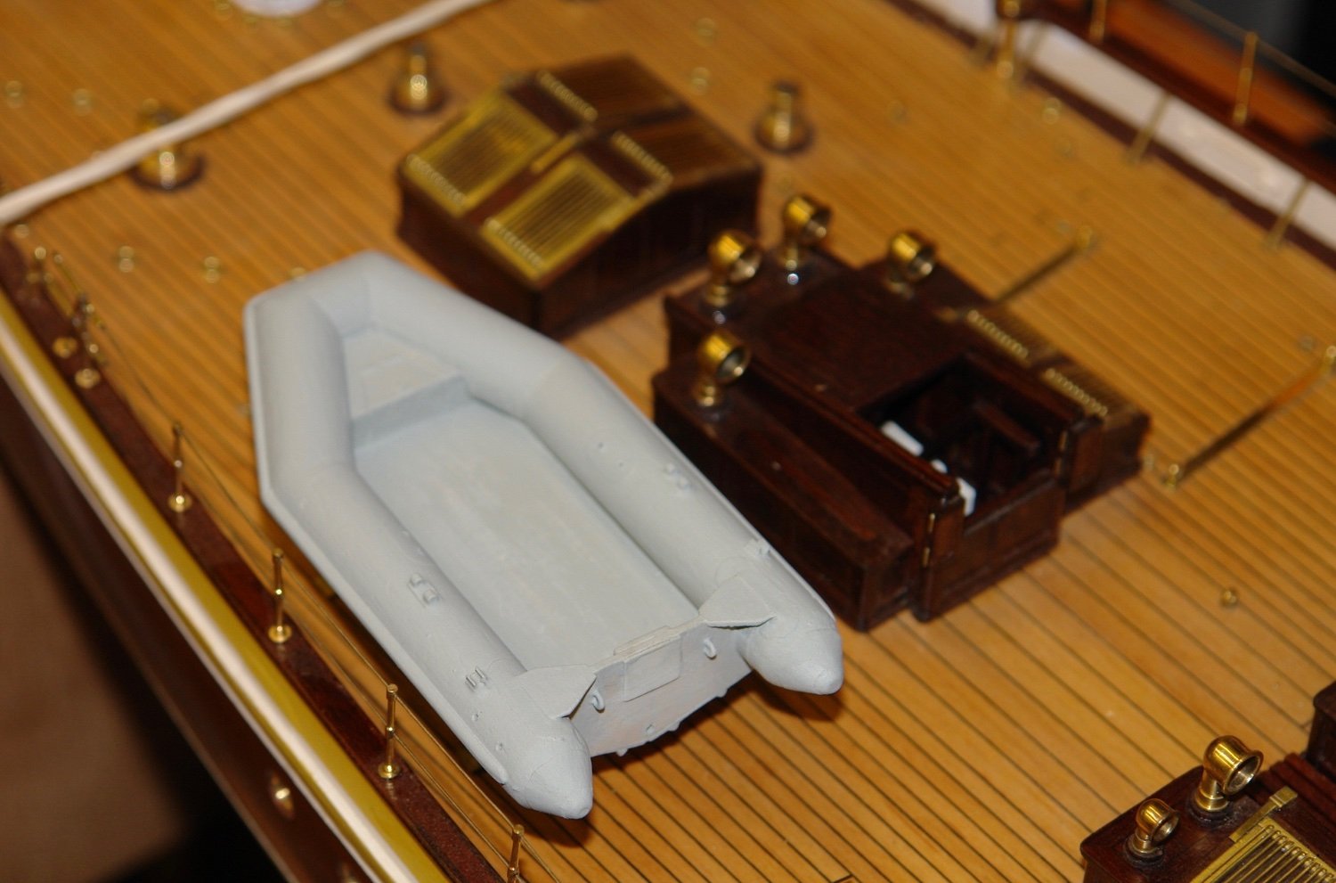
but perhaps just a little out of place alongside all that shiny teak and brass!
Chris - I have to agree. I had to work hard to convince myself to include it. Thank you Eberhard.
- mtaylor, Mirabell61, Keith Black and 1 other
-
4
-
Thank you Pat and Keith.
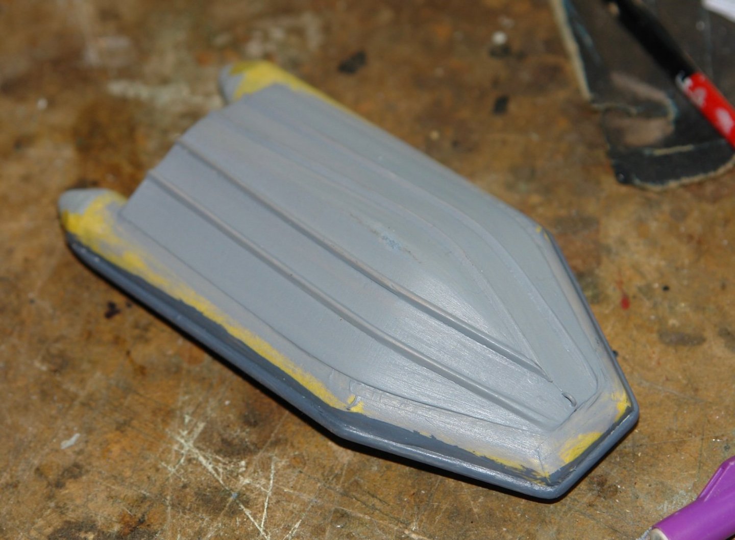
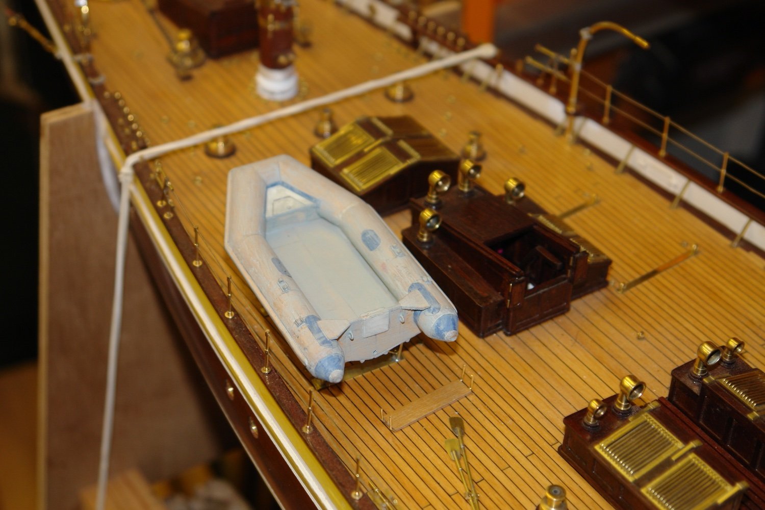
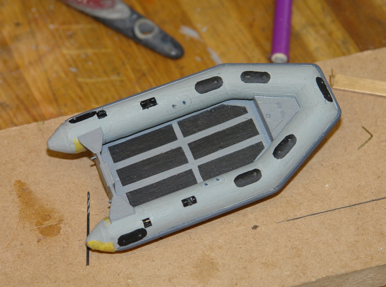
A bit of time was spent on the dinghy over the weekend.
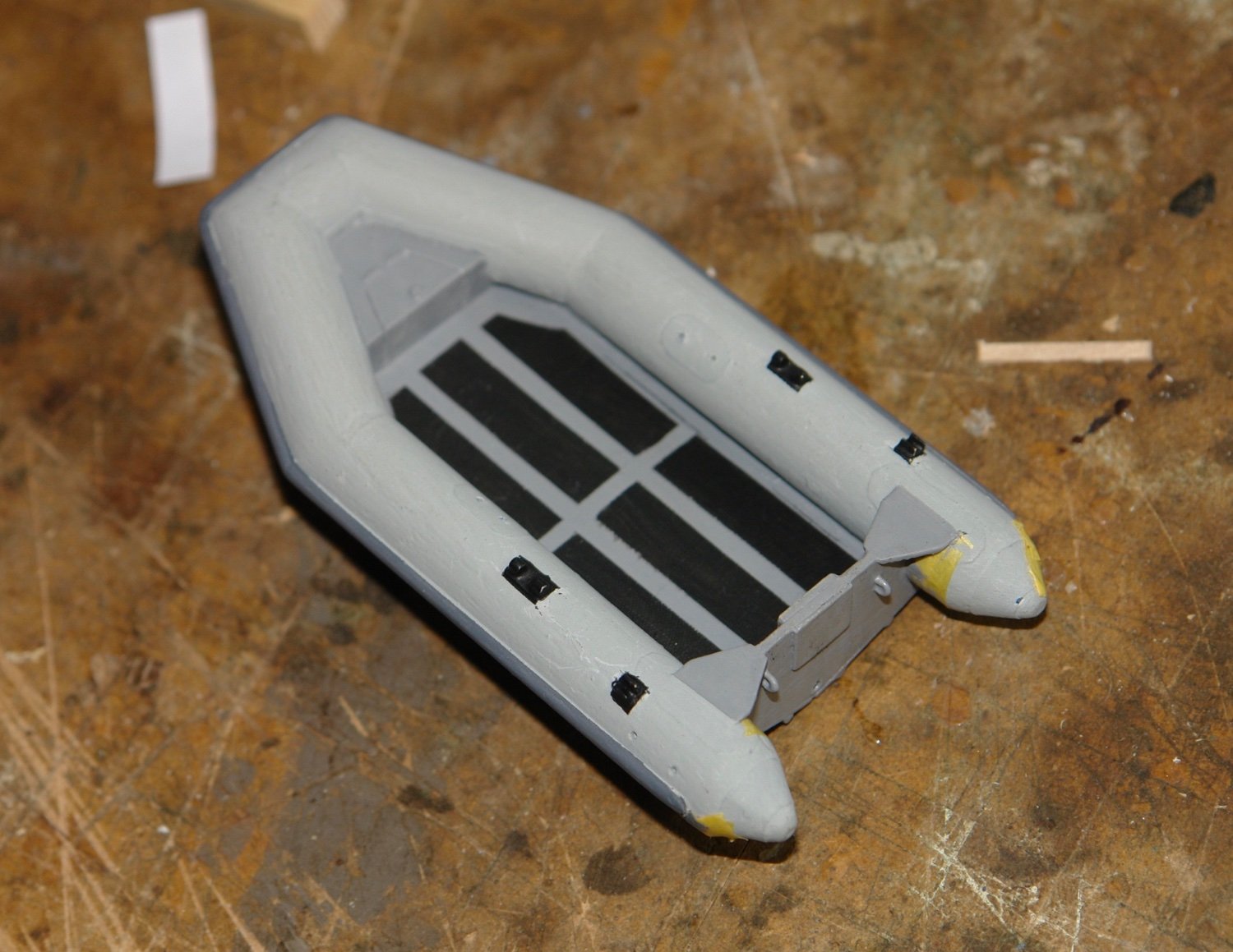
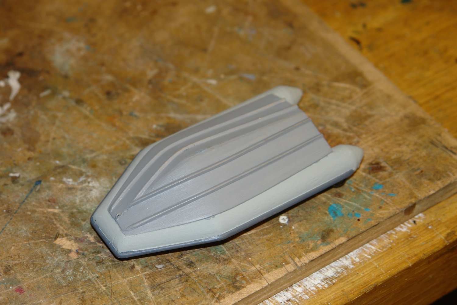
I started with a few coats of thin enamel paint with sanding between coats.


Then I did a bit of masking and applied black paint to rowlocks and oar clips and shades of grey to the bumpers, deck and solid bottom.
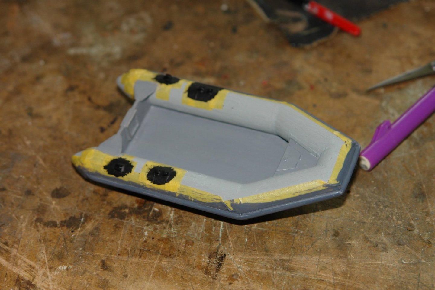
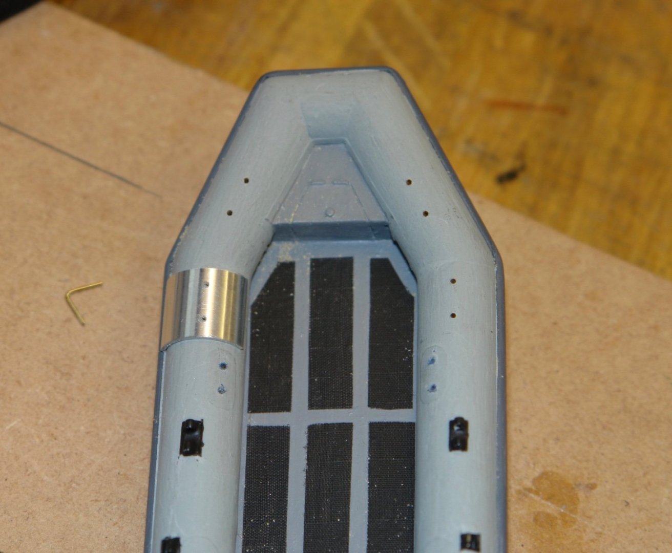
Anti- slip strips were required for the deck - made from sail repair tape blackened with permanent marker.

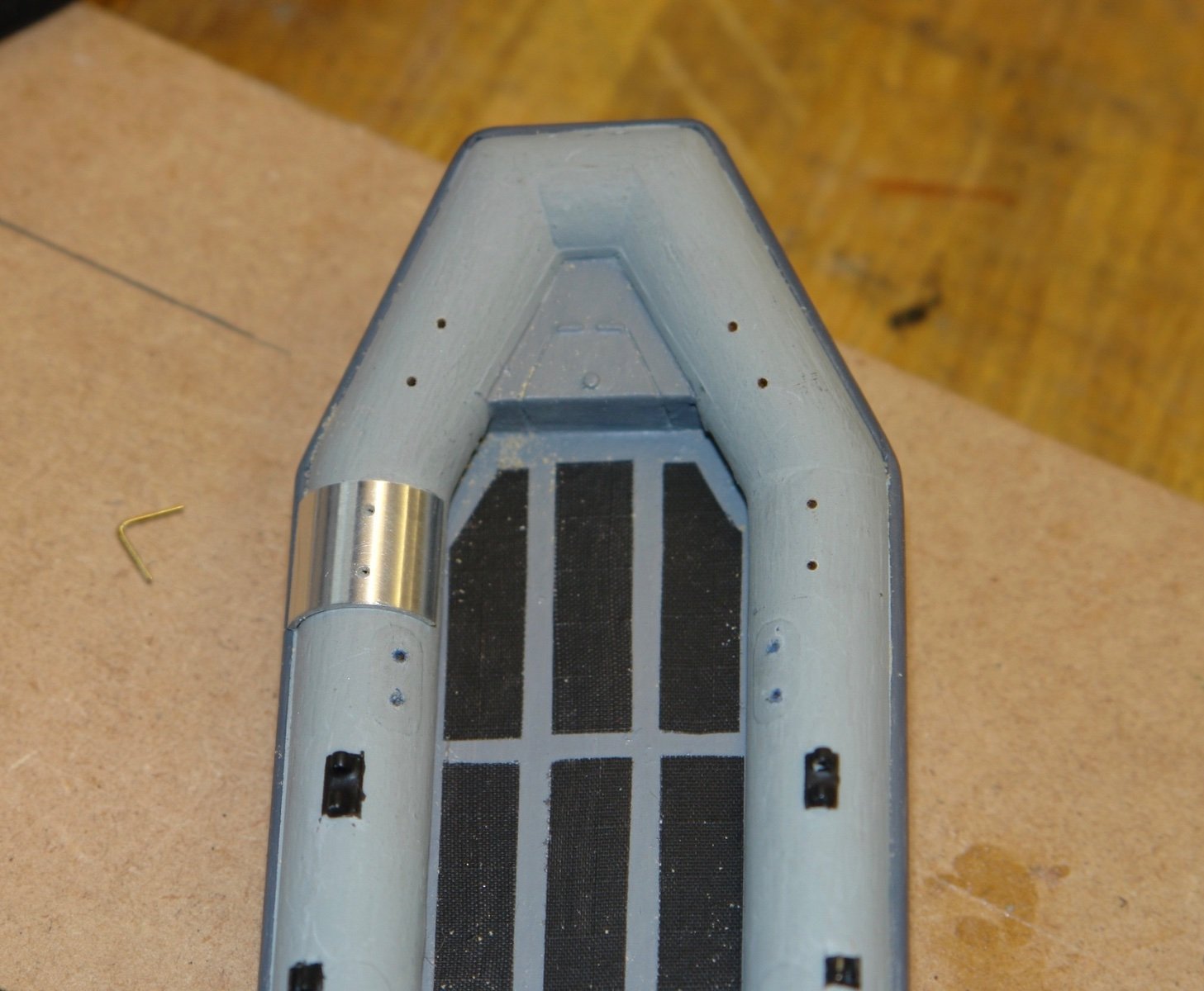
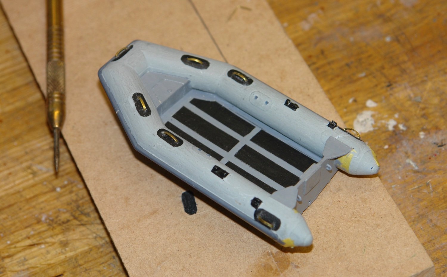
Grab handles were needed on the sides and I made a drilling jig out of a piece of aluminium tube to get the attachment holes correctly spaced.
Fabric reinforcing was cut from sail tape.

This was also coloured and applied.

The handles themselves were made from flattened .031" wire. These were attached and painted black.
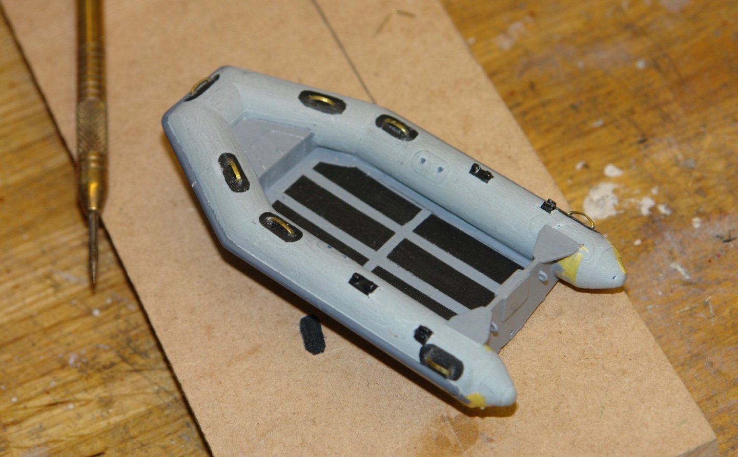

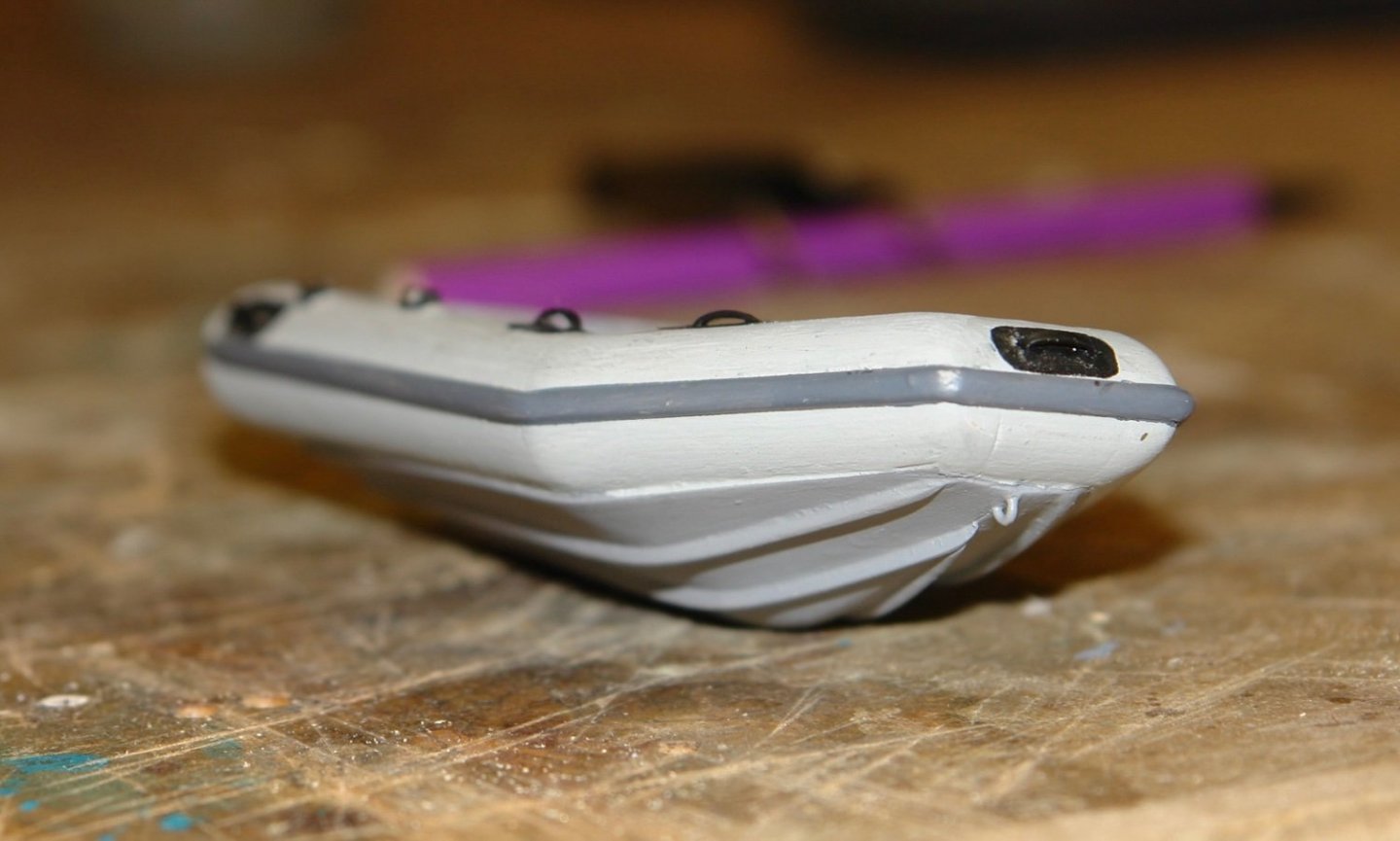
A further bit of anti-slip matting was attached to the locker and the oars were glued permanently in place. 3 black inflation valves were also added.
-
-
3 hours ago, NavyShooter said:
Had to dig out the canoe to affect a rescue.
I have realised the great advantage of the 3D approach to model making is that if the worst happens you can just print another one. I may become a convert. Nice model.
- mtaylor, NavyShooter, thibaultron and 2 others
-
5
-
Lovely deck view Nils, lots of eye catching detail.
- LEFEBVRE, mtaylor and Mirabell61
-
2
-
1
-
Also rather than a pin vice for drilling small holes you might want to consider one of these.

My son bought me the kit as a stocking filler - to some extent as a joke, but surprisingly i find myself using it to drill awkwardly positioned holes where I would normally revert to a pin vice. The speed is very low - probably 400 rpm and the collets only go up to 3mm (.118") so it is a bit limited.
A review:- https://doogsmodels.com/2012/07/24/gear-review-tamiya-electric-handy-drill/
-
-
Thank you all for your comments.
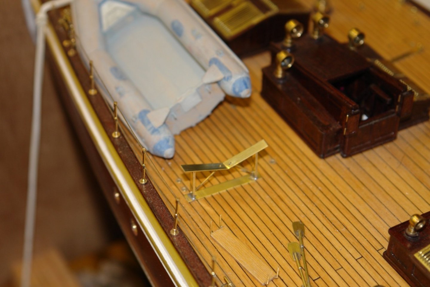
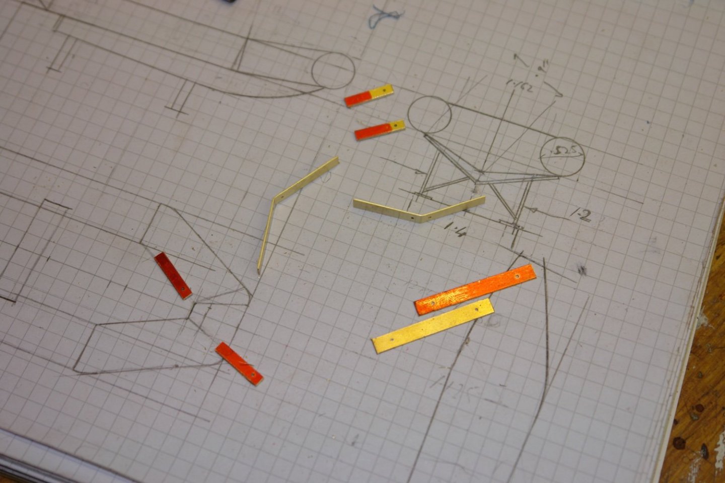
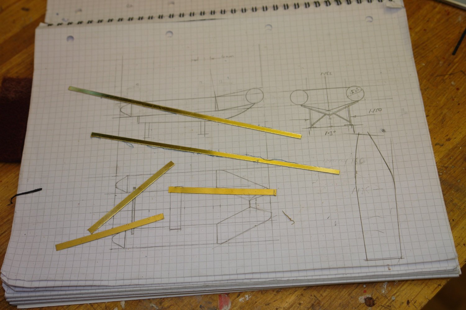
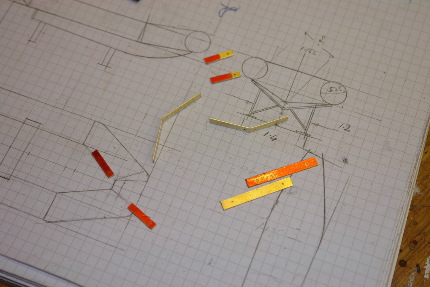
The dinghy sits on a metal frame constructed from .032" and .040" brass sheet.
I started with a drawing before cutting off the required widths of brass strip from sheet. The strips in the next photo sit above the sketch. The front and rear frames are of differing shapes to accept the changes of shape in the dinghy hull. The frames are circa 1.3" x 0.8'. The legs are .040" thick and the cross pieces 0.31" thick. The diagonal braces are made from .040" wire.

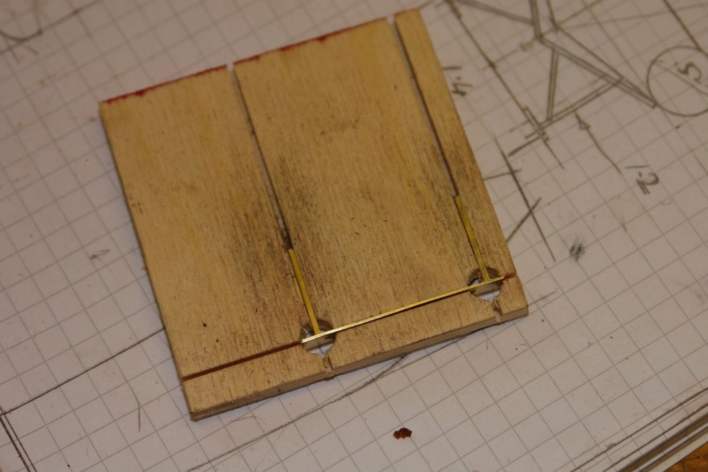
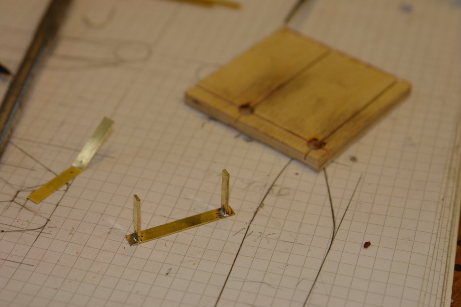
The pieces were cut accurately to length and the "V" was bent to the correct angle. .040" holes were drilled to accept the bracing rods.
I made a jig to ensure the soldering of the upright to the base strips was at 90 deg. The jig was just slots in a piece of 1/4" ply with intersections drilled out to give access for soldering.

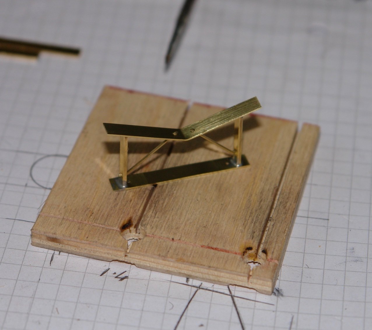
The "V" strip was then soldered in place with the base held against a piece of steel to act as a heat sink.
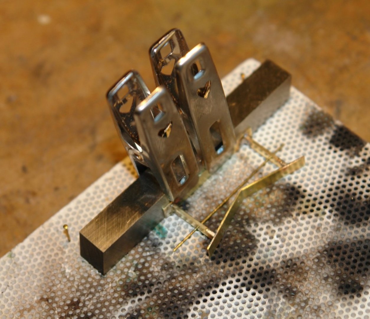
Finally the bracing rods were soldered in place and the supports were then cleaned and polished.

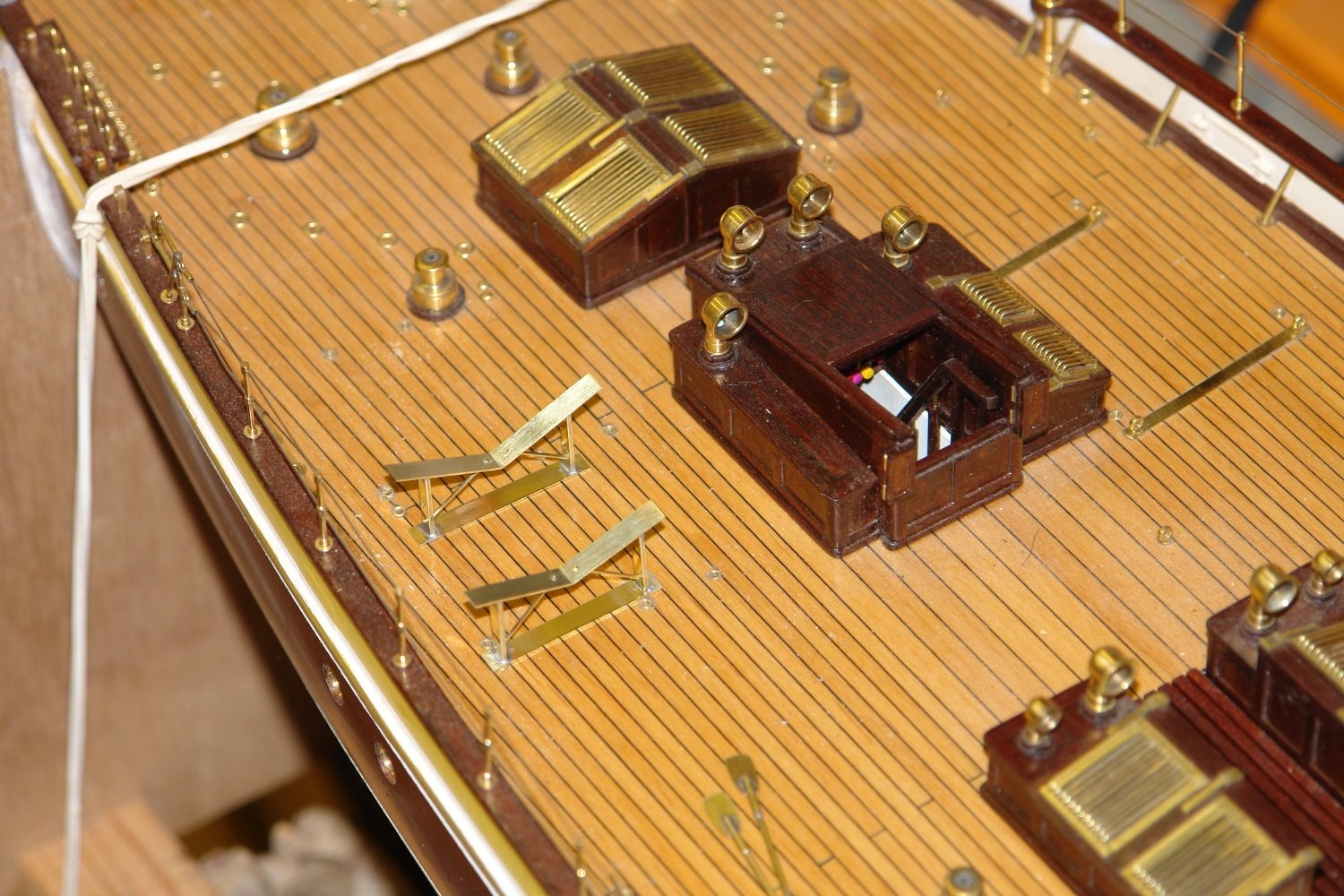
Finally the frames were glued and pinned to the deck.
The garden is still dominating my time so progress is somewhat limited I am afraid.


H G Berry 1853 by Jond - FINISHED - 1:64 - Boothbay Brig
in - Build logs for subjects built 1851 - 1900
Posted
You seem to be cracking on at quite a pace Jon. i agree the deck accommodation does seems to be on the ample side.