KeithAug
-
Posts
3,980 -
Joined
-
Last visited
Content Type
Profiles
Forums
Gallery
Events
Everything posted by KeithAug
-
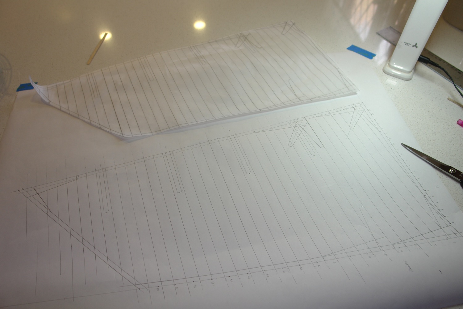
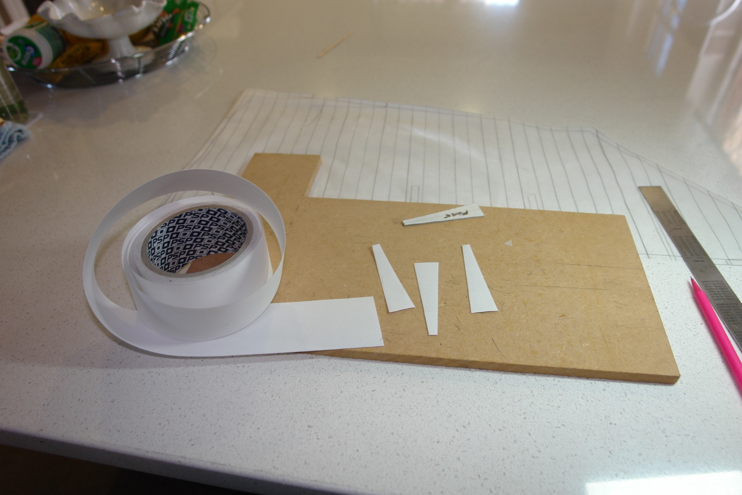
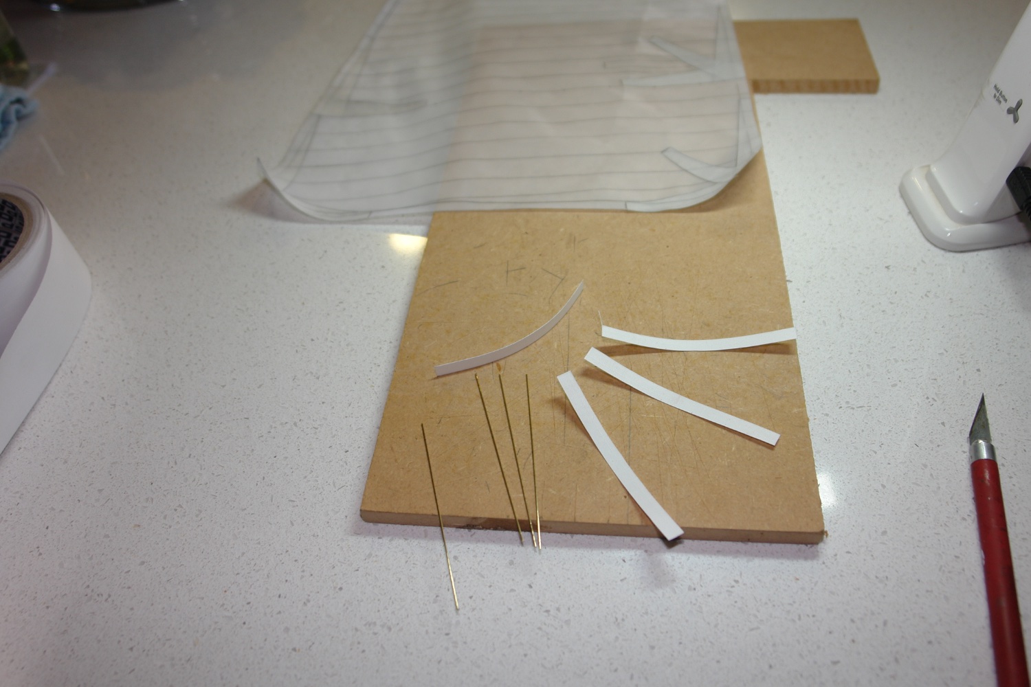
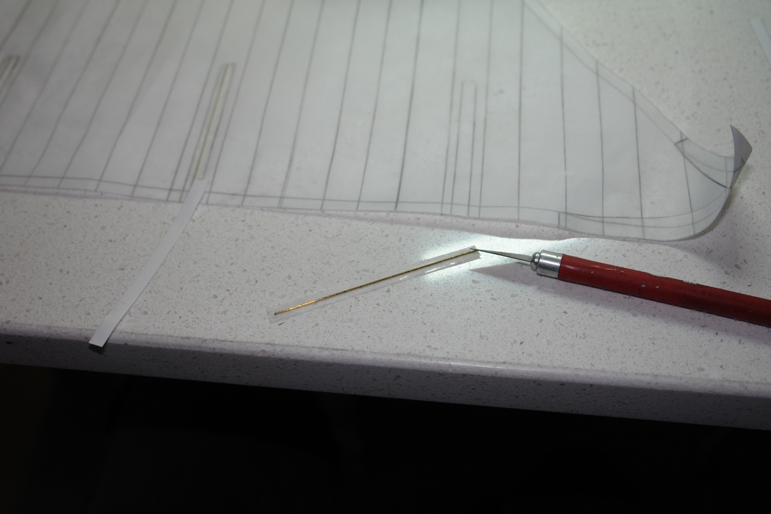
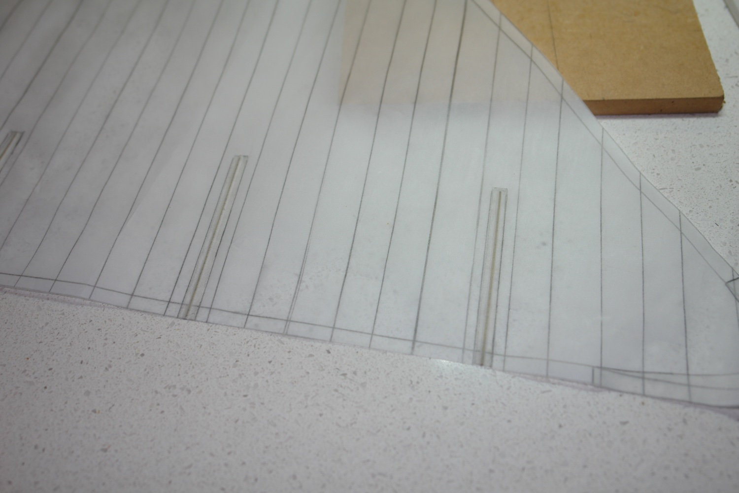
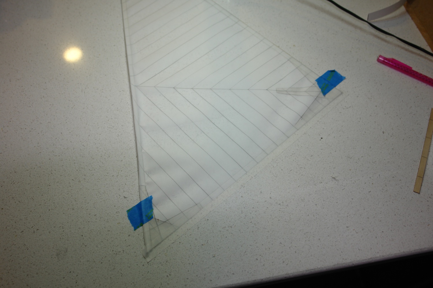
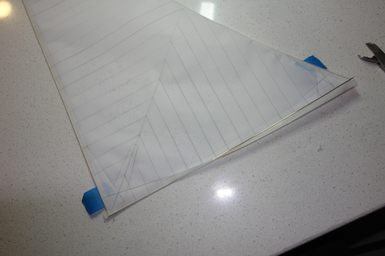
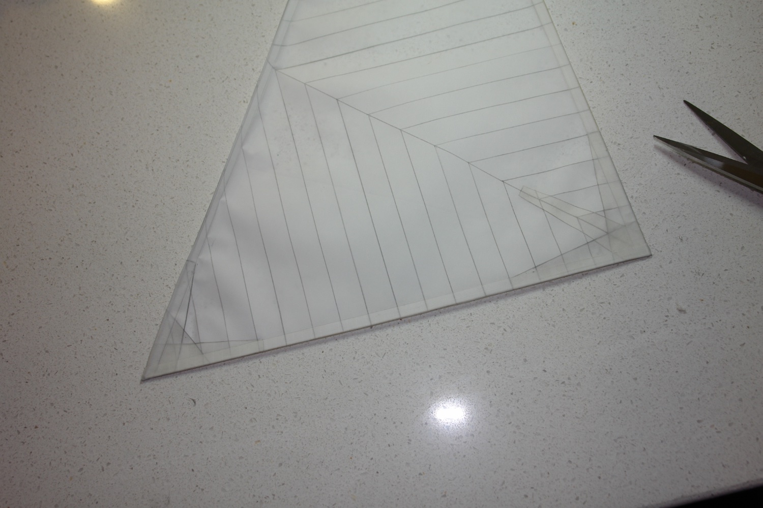
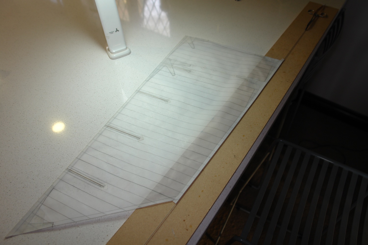
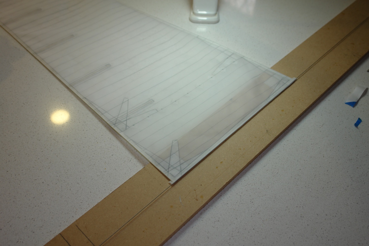
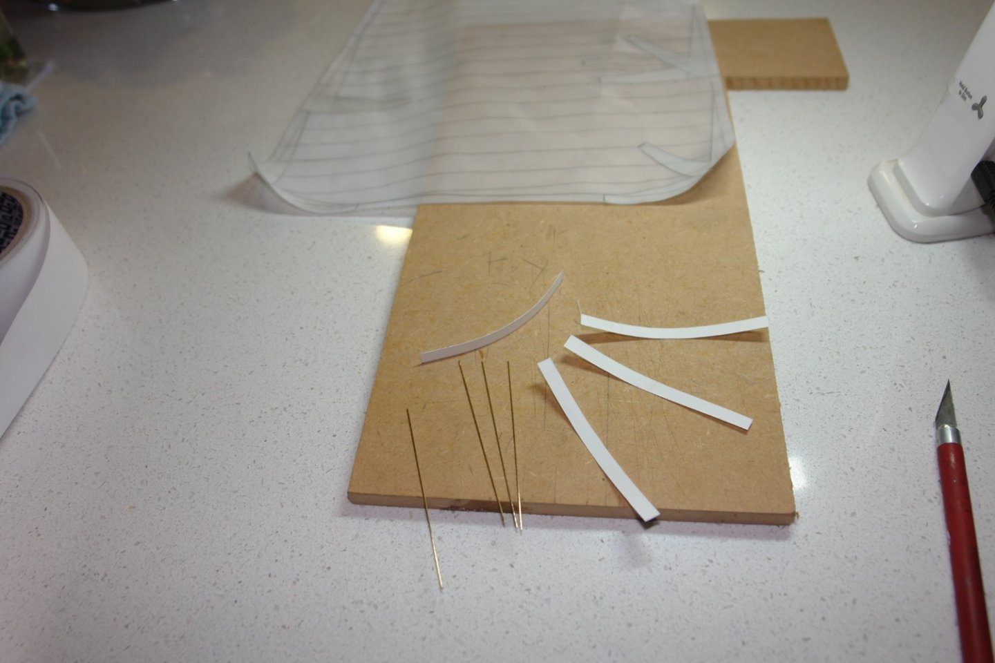
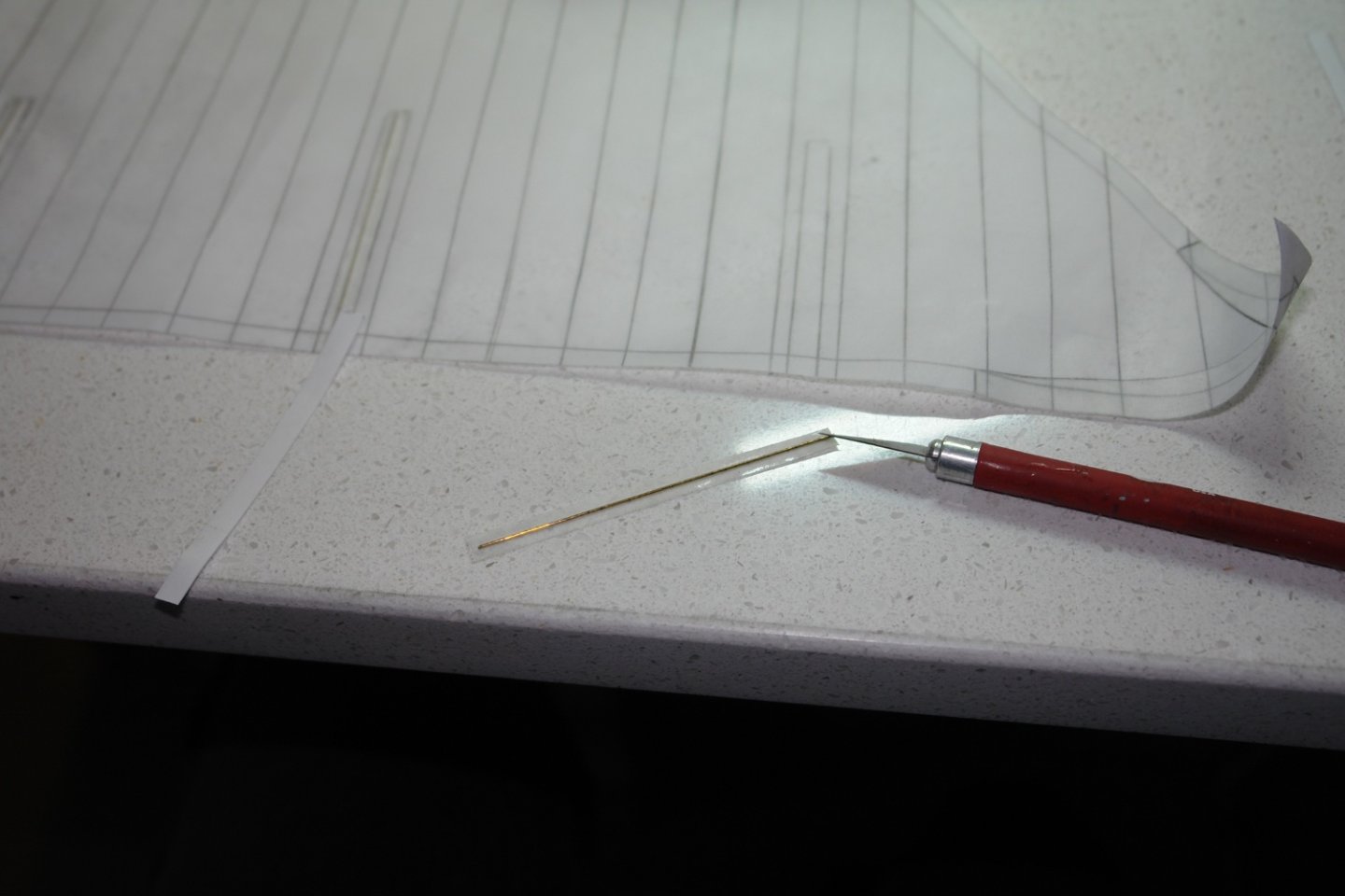
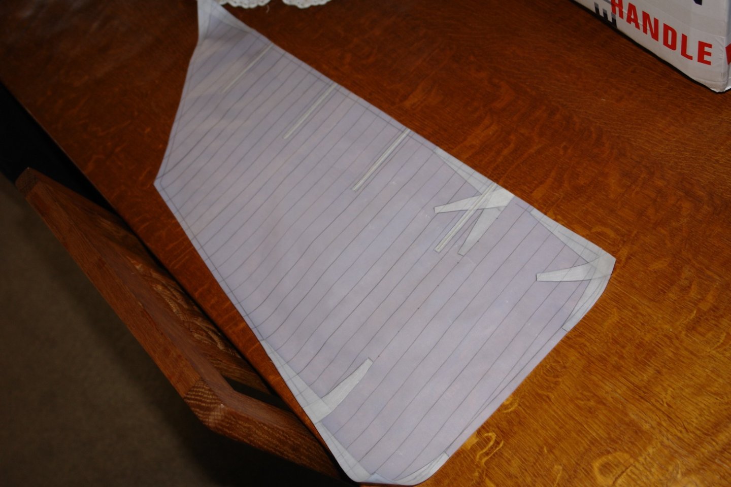
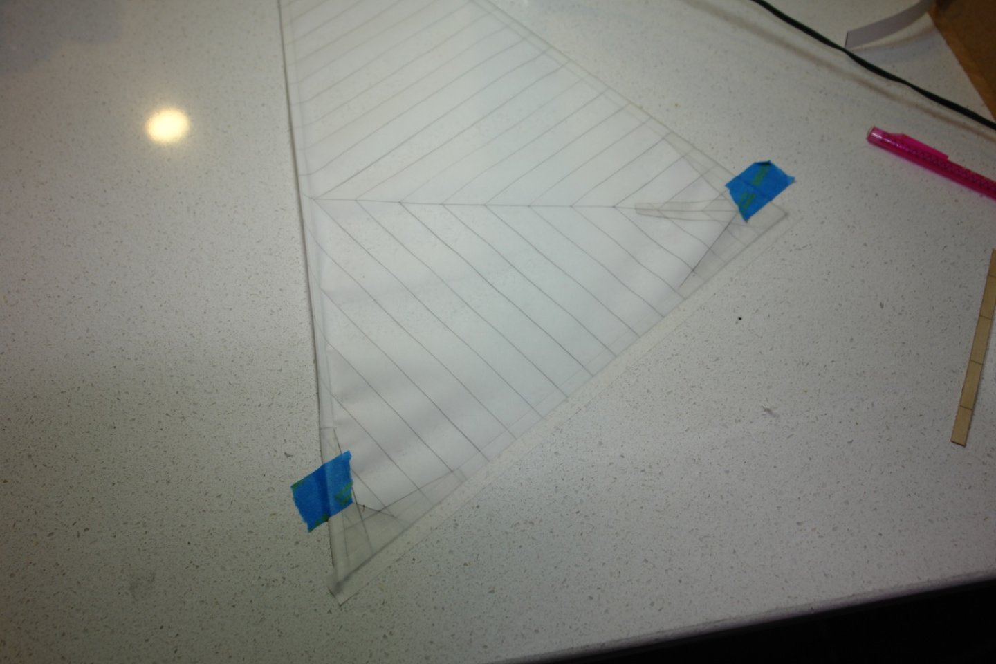
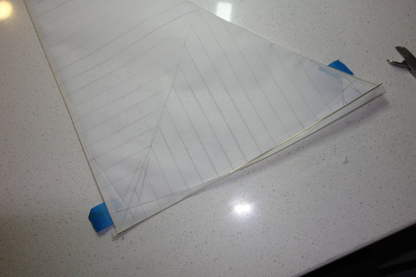
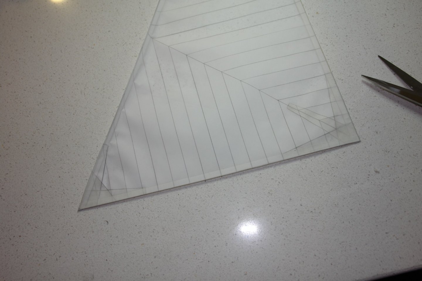
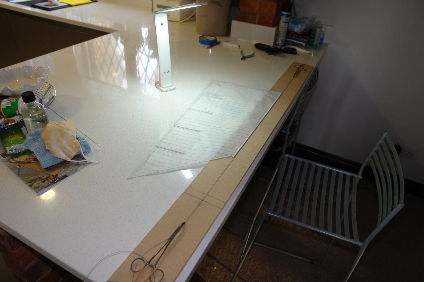
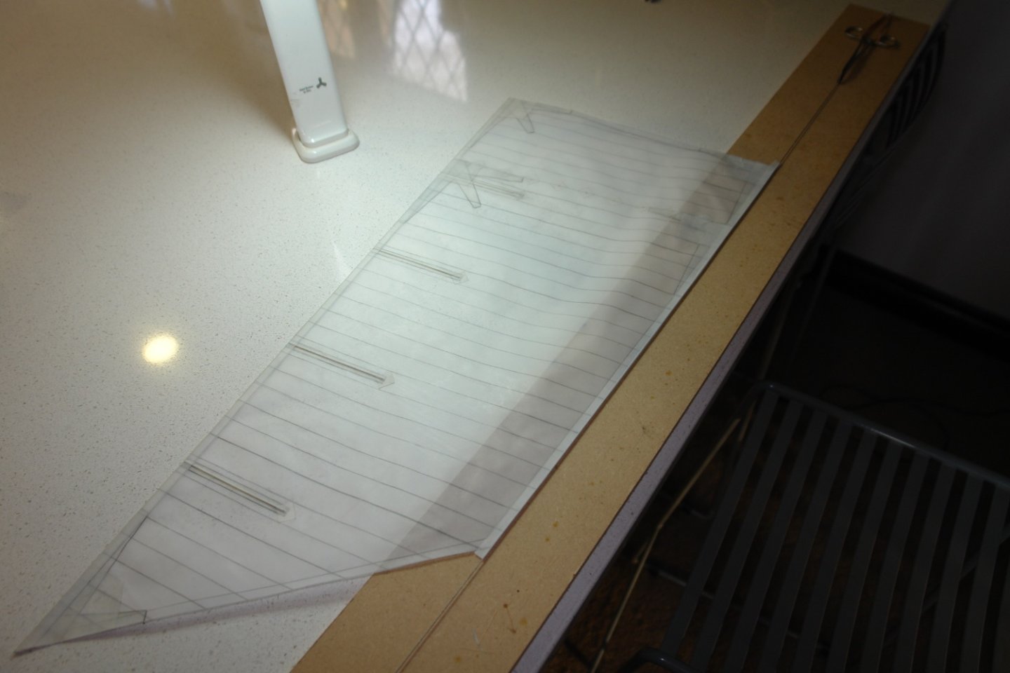
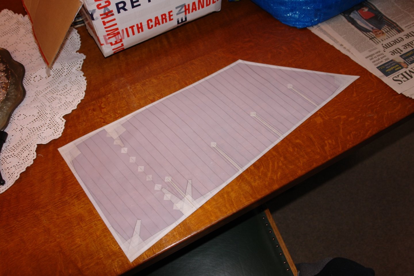
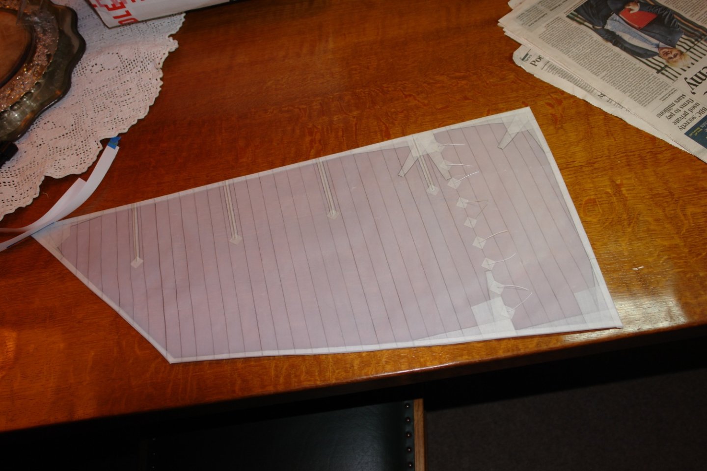
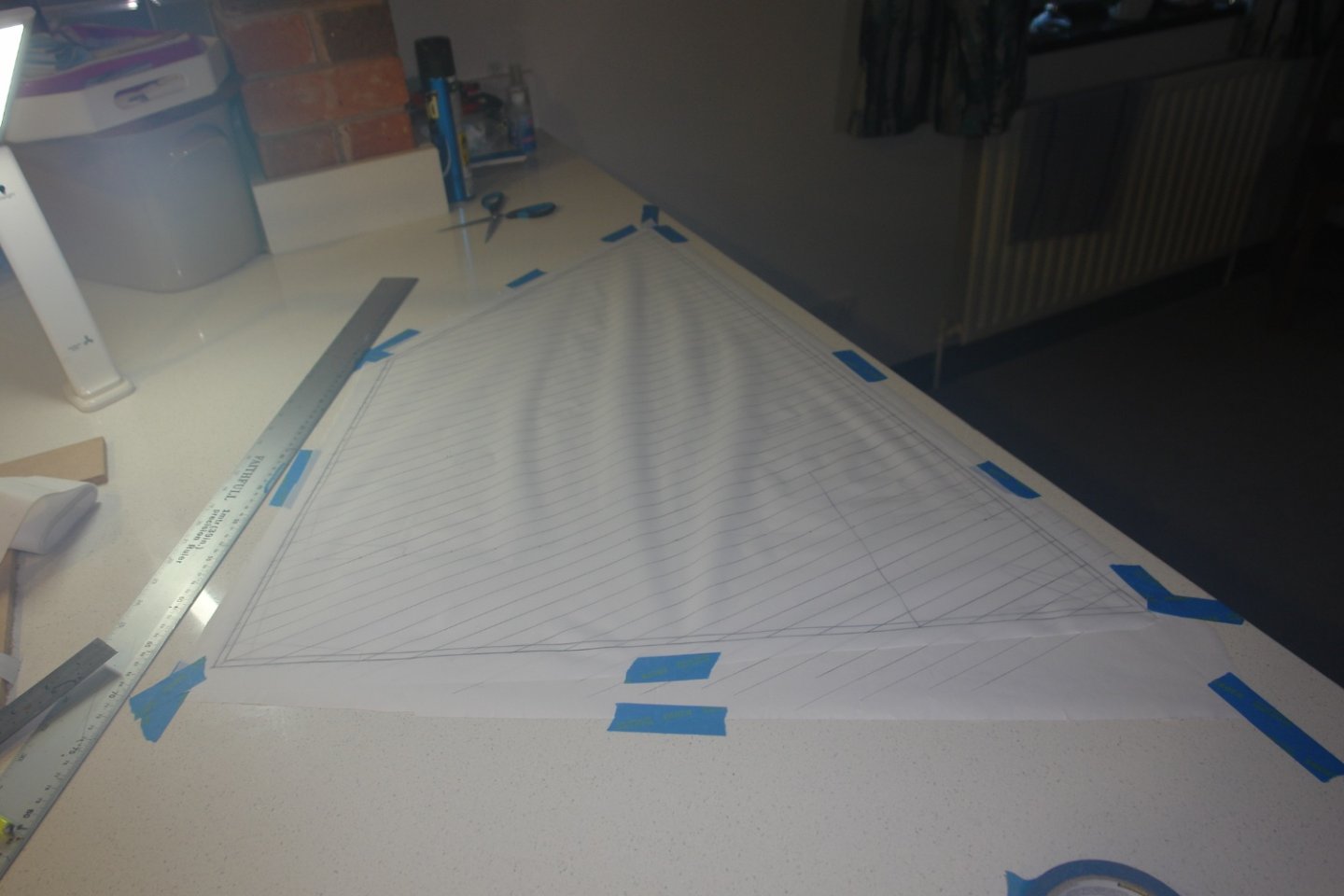
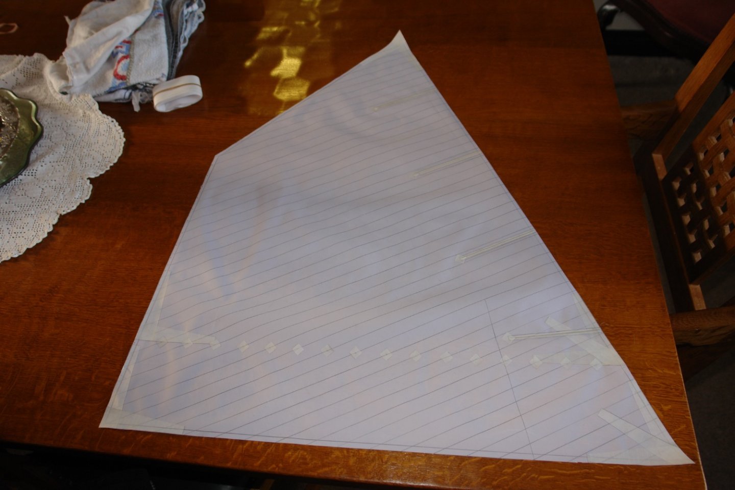
 Hi Keith - she was searching a wide area to the south west of London as far south as the west coast, but in the end she bought a house about 6 miles away from my wife and I in West Sussex. Brian I haven't taken one recently but I should be getting some of the sails hoisted over the next few weeks. I will make a point of taking an overall shot and posting it soon. Keith, Brian, Pat, Richard, Eberhard, Nils, Gary and Dan. Once again thank you for your continuing support and comments, i do appreciate the time and effort you take in following along. Also thanks to everyone who has visited and or liked my work. I am now in a phase of sail making. I started this in the last post but didn't provide much detail so I will correct this here. I sketched out the foresail on paper and then repeated the process of tracing the seams and reinforcing details on to the PVA impregnated cloth. I then cut wedge shaped templates for the reinforcing from plasti-card. These were then used to cut out reinforcing from rip stop tape. I also used templates to cut out the batten pockets. The batten's were cut from hard brass wire and this was attached to the adhesive side of the rip stop tape. The tape and batten's were then attached to the sail. The reinforcing wedges (made earlier) were then applied. I always think sails with wavy leaches look bad, and even if the sails can't be made taught across their surface they look better with straight or continuously curved leach. It would have been preferable to have the sails modelled as though they were full of wind but getting the curvature set into the sail (given their size) isn't something I know how to do. Because the luff is supported along its length by the mast rings and is tight between the goose neck and the gaff saddle I dint need to worry much about it being straight. I did however reinforce the luff by setting into it a (0.031" diameter) length of braided wire. This was stretched along the luff before being bound in place using rip stop tape. The head and foot were done in the same way as they are also constrained to be straight by lacing them on to the boom and the gaff respectively. The leach was done slightly differently by attaching a length of (0.031" diameter) stiff brass wire alone the edge. The reinforcing around the reefing points and the ends of the batten's was then attached thus completing the sail (except for the clews). I then moved on to the jib sails following a similar strategy, however both the leach and foot was reinforced by stiff brass wire while the luff was reinforced by the braided wire. I have done 5 of the sails, the main and fore sails, and the 3 jib sails. I have left the topsails to be tuned for size once the main and foresails have been fitted. I don't suppose I have pleased many of you purists by my sail making approach but I am going for looks over authenticity.


-
lovey work on the winch and other fittings.
-
Roger - The brass work has come along really well. One step forward and two back is possible, if I were you I would celebrate two forward and one back.
-
Hi JD Nice work on the planking. in some of the shots the planking wood looks quite fibrous. is that the case or is it just the magnification?
-
The close up photo of the bridge helm position is particularly charming. What is next Ras?
-
It is remarkable how quickly you work Nils particularly given the detail and quality you achieve. Excellent job and i look forward to the next one. Keith
- 180 replies
-
- 3
-

-
- pilot boat
- Elbe 5
- (and 3 more)
-
Beautiful detail Keith - creating the rigging detail must be a real challenge and you are doing so well.
-
looking really nice Hakan. Beautifully clean work as usual.
-
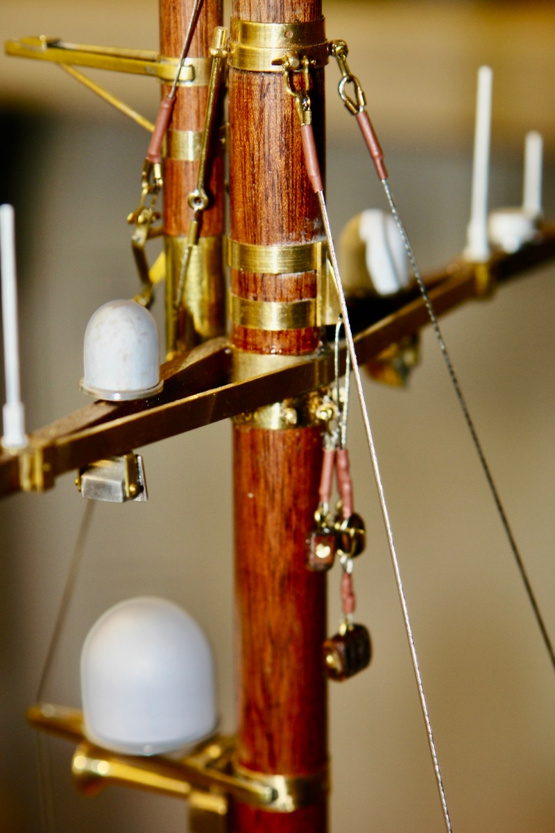
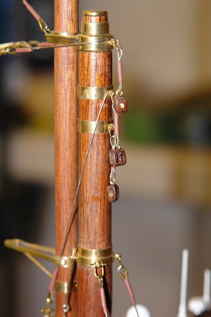
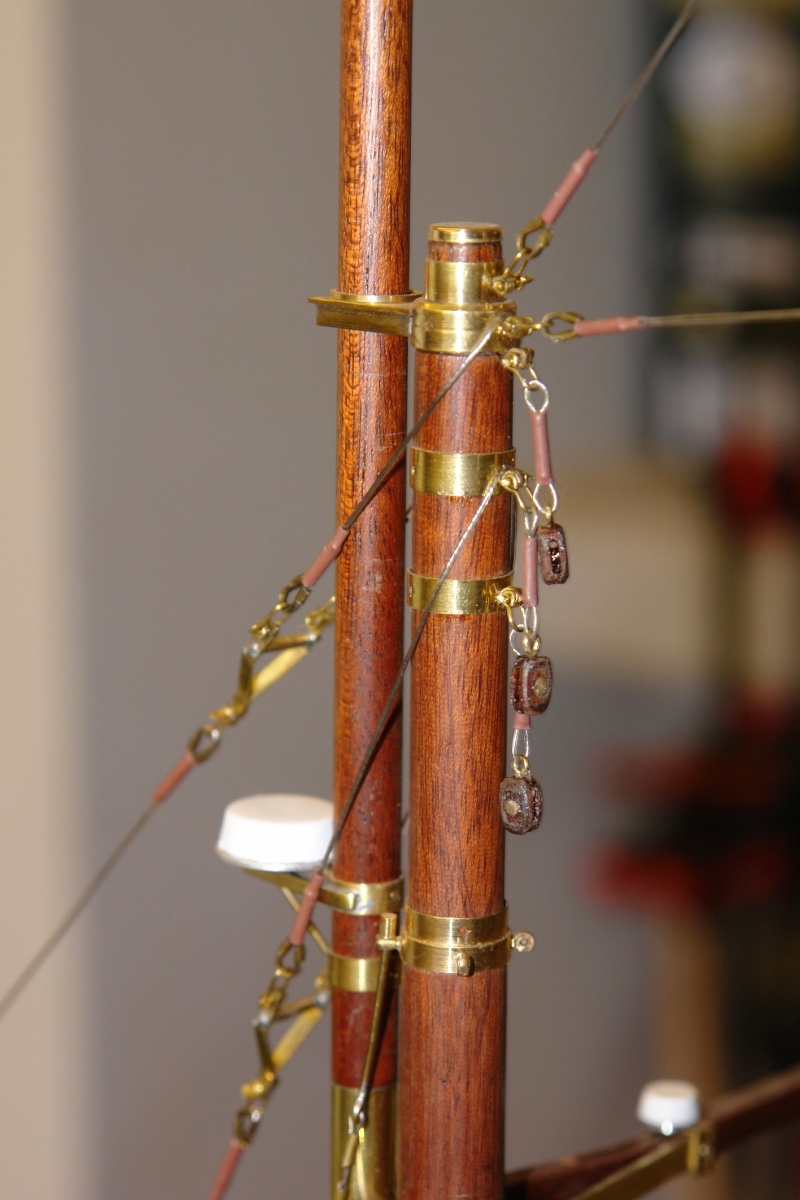
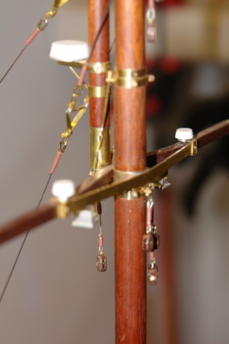
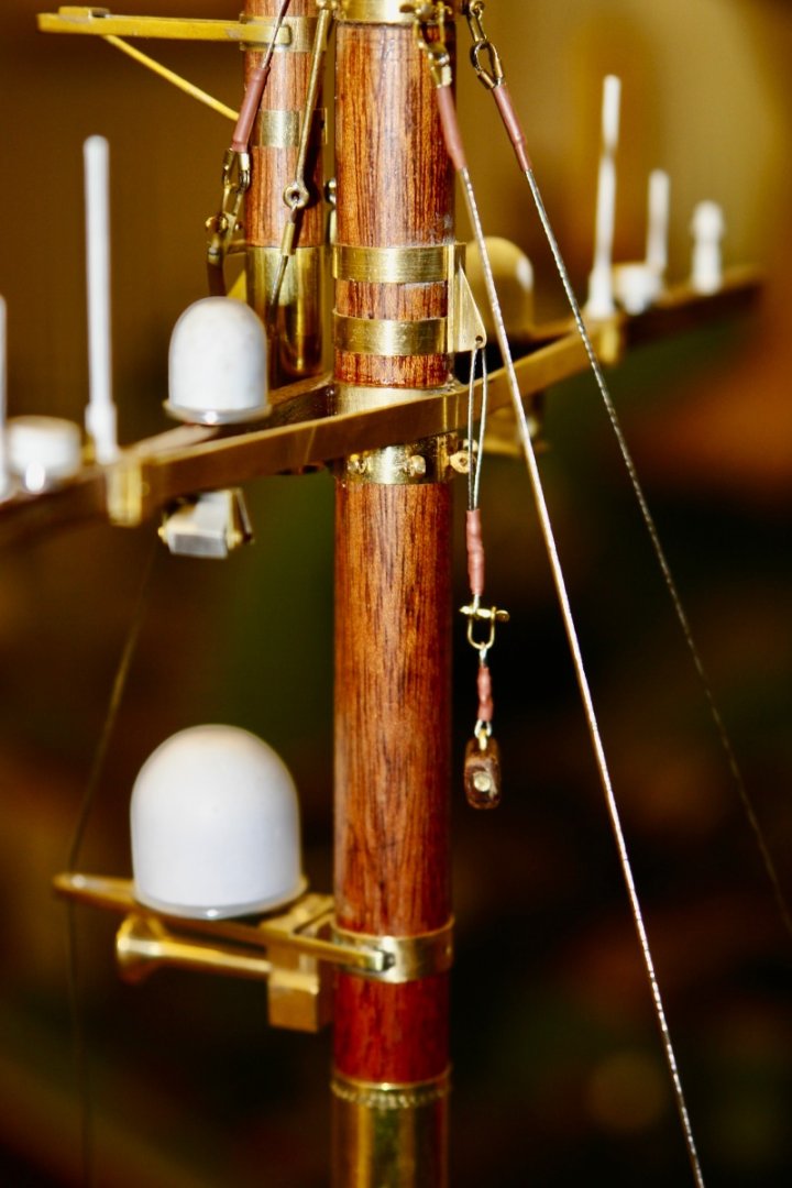
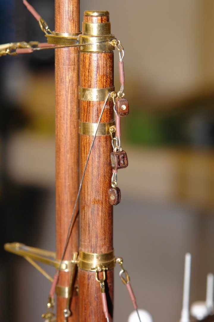
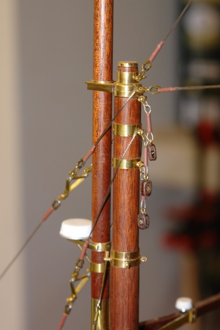
Well that was a bit of a lay off. My daughter bought a new house (at least new to her) and I have been doing various jobs. She has job in the city but the covid revolution means she can now do it from home so she has relocated to the countryside. I still have some jobs to do - particularly the garden which will take a while. I have managed to do a few boat jobs so this is a bit of a catch up. I have done all the block attachments to the masts. It took a while but here are the results. This is the main mast with the gaff saddle hoist block attached. Next the two topping lift blocks are attached to the main mast. Next the main mast gaff bridal blocks were attached. Then the fore mast bridal blocks. Then the fore mast saddle hoist block , the topping lift blocks and the spinnaker boom block. I also made a start on the sails, firstly by drawing patterns for the sails / seams and then transferring the seams on to the sailcloth using pencil lines. I'm not among those of you who diligently practice you sewing skills. I started with the mainsail (which is huge). I then applied the reinforcing using ripstop adhesive tape.


-
I was quite enjoying hearing about all your youthful misadventures. The kids of today will be thinking you are all delinquents.
-
Looking like a very interesting build. I think I’ll tag along.
- 24 replies
-
- 2
-
-
- De 13 Søskende
- sail
- (and 5 more)
-
HMCSS Victoria 1855 by BANYAN - 1:72
KeithAug replied to BANYAN's topic in - Build logs for subjects built 1851 - 1900
Maybe it works better in the northern hemisphere where it was made😁😁 bath drain effect 😁- 1,013 replies
-
- 10
-

-
- gun dispatch vessel
- victoria
- (and 2 more)
-
Mini spot welder to weld railing
KeithAug replied to modeller_masa's topic in Modeling tools and Workshop Equipment
I can think of a number of pros and cons for welding vs soft soldering. Why are you preferring welding? -
Yes Brian, our generation seemed to have lots of risky toy opportunities. My chemistry set even had a bunsen burner which I used for a bit of glass blowing. The kids today don't know what they are missing. On the theme of safety I hear they have pulled Humbrol enamel paints because of safety concerns. My understanding they are reformulating them prior to relaunch. In my experience "reformulating" is a euphemism for making stuff worse at doing its job. All of us who have used Humbrol paints since childhood should be considering legal action.
-
Eberhard I left Rolls Royce in 1978 and joined BNFL based at Risley but working mostly on Sellafield projects. Initially I worked on Magnox reprocessing projects before moving on to take over the flowsheet design for the Thorp plutonium purification plant. I then moved on to waste treatment and was responsible for the design of the low active effluent treatment plant. After that it was solvent treatment as mentioned previously. Then Three Mile Island and Chernobyl happened and everything changed. I left BNFL in 1988 and moved to brewing where I damaged a lot more peoples lives than I ever did with nuclear energy.
-
Yes I agree. I was once in charge of a team looking into options for treating waste solvent from a nuclear reprocessing facility. The waste solvent (tributylphosphate in odourless kerosene) was stored on site and we needed some way of treating it. One of the chemists came up with the idea of reacting the solvent with hydrogen peroxide and for a while this became the front runner of the options. It never inspired me as a great option as it seemed too much like rocket fuel to me. Anyway it was eventually dropped as an idea.
-
Keith, yes it all depends on the type of plastic. Have you ever ever tried mixing hydrazine with peroxide - it makes wonderful rocket fuel and has even been known to dissolve pilots😬