HOLIDAY DONATION DRIVE - SUPPORT MSW - DO YOUR PART TO KEEP THIS GREAT FORUM GOING! (Only 36 donations so far out of 49,000 members - C'mon guys!)
×


Cathead
-
Posts
3,494 -
Joined
-
Last visited
Content Type
Profiles
Forums
Gallery
Events
Everything posted by Cathead
-
 For what it's worth, I'm not sure about Chaperon's later era, but in my understanding the hog "chains" on earlier boats were generally solid metal rods, not cables or chains, meaning they can be simulated with straight brass rod. I assume Kurt knows the proper details for Chaperon. Model's looking great. I see what you mean on the wheel timbers, I didn't notice in the oblique views of your first post but it's more clear in the side views. The good news, at least, is that no one who isn't a serious expert will likely notice, although I know what you mean about the frustration of finding something you know about and can't really fix.
- 76 replies
-
- 2
-

-
- model shipways
- chaperon
- (and 1 more)
-
Bob, Yeah, central Missouri really was the focus of this storm. Check out this snowfall map from last night, posted by the St. Louis National Weather Service office. We're near the center of that bullseye, and the totals have gone up since then. It's still snowing as I type, though only flurries at this point. I loved snow growing up and still do, but being a home/landowner does change one's perspective on the ratio of fun/work it can cause.
- 599 replies
-
- 3
-
-
- sidewheeler
- arabia
- (and 4 more)
-
Plaster is a great idea, as I agree the wood grain was obnoxious. However, I don't have any and can't think of any other use, so am reluctant to buy it just for this tiny application. I'm guessing I can't buy just the half ounce I need? Or are there other relevant uses that would justify buying a larger quantity? And what kind would you suggest?
- 599 replies
-
- 3
-
-
- sidewheeler
- arabia
- (and 4 more)
-
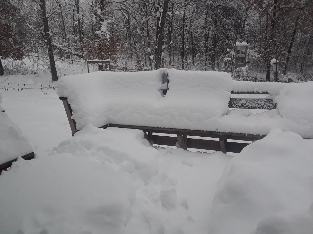
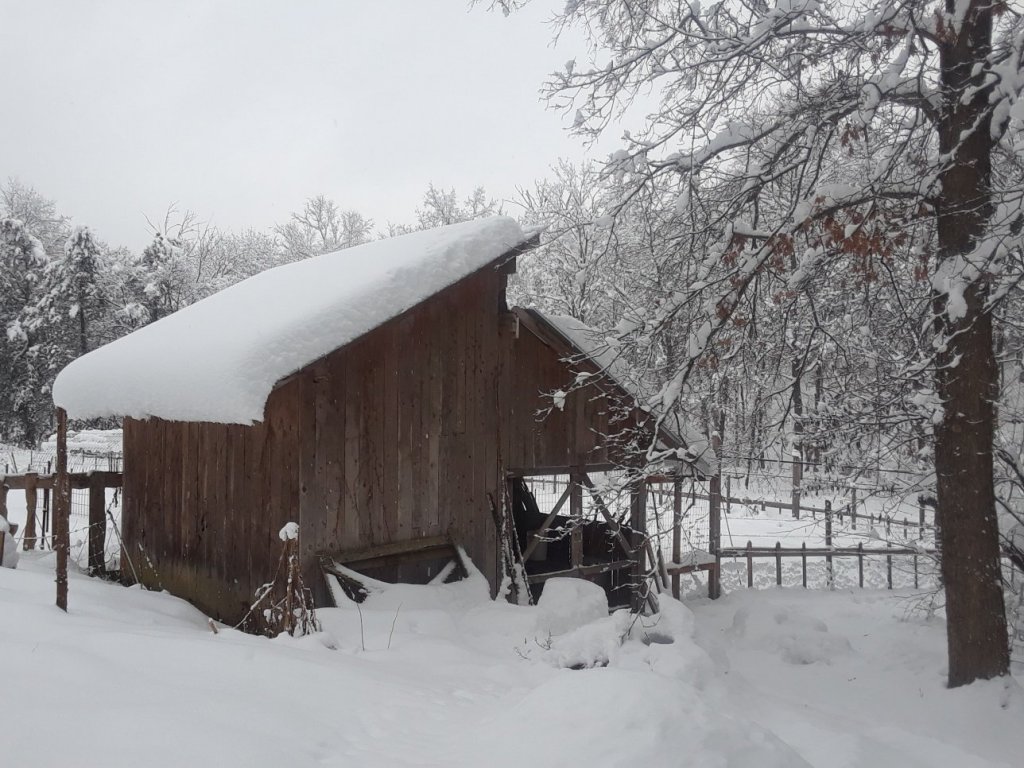
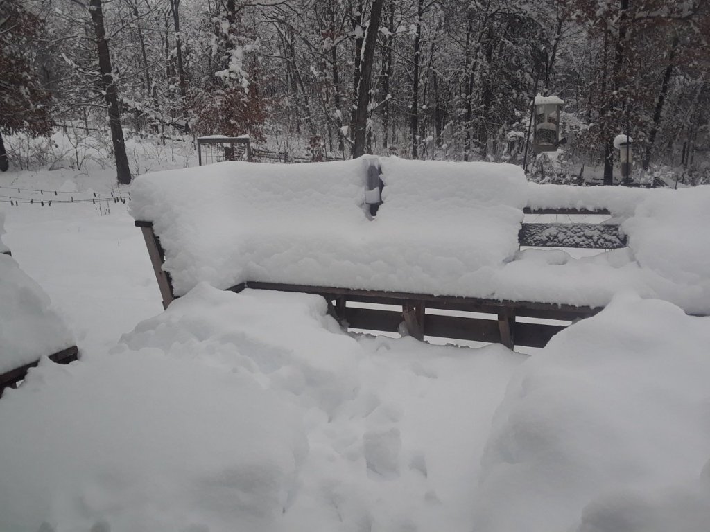
So, you know how I said we had a "snowy weekend" coming up? Well, that turned into the third-highest snowfall on record for this part of Missouri at 16.4" as of this morning and it hasn't stopped (that's over 40 cm for you folks in sensible countries). Where I grew up, along the Great Lakes, this wouldn't be all that special, but out here in the southern Midwest it's pretty spectacular. I'd enjoy it more if it didn't create so much work, between trying to plow out our long, steep driveway (we live in a narrow rural creek valley) and working to keep our hundreds of young pine trees and fruit trees from breaking under the strain. Here are a couple photos, which don't do the snow justice as it's already begun to settle and compact. It was nearly to my knee and I'm 6' tall (and we had no wind, that's all straight accumulation, not drifting). We moved here in 2006 and have now been present for three of the top five snowfalls on record (going back to at least the late 1800s). One of my full-scale wood projects, a garden shed built entirely from cedar we cut and milled on-property. Kitchen porch buried. The bird feeders need air traffic control, but unfortunately they're furloughed due the the US government shutdown. Anyway, due to the scope of this storm I didn't do as much model work as I hoped, but made some progress. The basic boiler structure is essentially done, though I may add a few details. I also made the brick paving that goes in front of the furnaces, so ashes could be scooped out without setting the deck on fire. Here's a portion of the original from the museum: And here's my version, made by carving a piece of wood with a razor saw and file, then using multiple layers of stain and pastel to subtly vary the bricks. It wouldn't stand up to really close scrutiny (like a camera lens) but it'll only be viewed obliquely on the model, so I'm not too worried. And here's a few shows of the boilers placed on the model temporarily. I also drilled holes in the engine assemblies and decks so I could set them in place using pins. This is nice because (a) they always go to the right (same) place now and (b) are more stable when on the deck. I'm not going to glue them on until the last minute because it'll be very useful to lay out the next deck on the open main deck. I think that, next up, I'll start laying out the boiler deck (the deck above this one, so named despite not having the boilers on it).
- 599 replies
-
- 17
-
-
- sidewheeler
- arabia
- (and 4 more)
-
Anna, There are various ways to bend a plank like that. I like to soak the plank in warm or hot water, which makes it more flexible. Then, when it's damp, you can clamp it into a curve and let it dry. Once dry, it will hold the shape you want. Some people advocate using a hot-air dryer (like for hair) either in place of water or after soaking. Either way, the heat helps loosen the wood fibers and make them easier to bend. Several warnings: First, different types of wood bend more easily or with more difficulty, so you have to be careful and bend slowly to find out whether your piece risks breaking. Second, you can clamp a wet piece of wood directly on the model if the wood underneath won't show (like structural bulkheads), but in your case as you've already placed other finished wood there, doing so risks warping the wood below. So I suggest finding a curve surface with a similar radius, like a pot or bucket, and clamping the plank you want to bend to that. Third, clamping too hard to compress the wet wood fiber and ruin the piece. Again, be careful as you do this. Sometimes it's best to use another, thicker piece of wood between your plank and the clamp to avoid direct imprints into the plank. I suggest trying this once or twice with scrap pieces if you have any, to get the hang of it before you try on a good piece. Good luck! On your next model, this is also how you would approach bending planks for the hull so that they have a smooth curve.
-
Definitely a nice touch. I've looked for some 1:64 scale figures for my Arabia but have struggled to find anything that seems appropriate.
-
Shopping on eBay: A Primer for Newbie Ship Modelers (Parts 1 and 2)
Cathead replied to ccoyle's topic in Wood ship model kits
Great topic. Another point I feel is important is Don't Be Cheap. Frugal, sure. Cheap, no. It costs money for small businesses to design, manufacture, and sell models. If you can't afford a model, you can't afford it; look for something else that's in your price range or learn to scratchbuild what you want. Sure, I'd like to have a nicer vehicle, but I'm not going to buy a stolen one to achieve that, or use a sketchy dealer that will likely cheat both me and the government. If I want to spend more money, I have to save or budget for that or accept that life doesn't revolve around getting what I want right now. This means don't get sucked into aggressively looking for crazy deals, because for the most part they don't exist. If you want a model, save up for it (or crowdfund it through gifts from family) and pay the reputable manufacturer (or dealer) what it's worth while feeling good that you supported a legitimate part of the small-business economy. Live (and model) within your means and pay others the respect of supporting their efforts to do the same. -
Great ideas, folks. I particularly like the advice to use a doorknob to save the palm. I had red spots on my hand for days from the pressure of the screwdriver handle. The stop collar is also quite sensible. In the back of my mind I kind of knew that others must have solved this before, but I got pleasure out of figuring out a way myself. Sometimes reinventing the wheel is fun when you're looking for a mental challenge, as I was when doing this. After a day working at a computer, research often isn't high on my recreational list but tinkering is! Unfortunately I haven't done much more than paint the assembly already shown. It's been one of those weeks where other stuff keeps getting in the way. Plus, last weekend was gorgeous so we went hiking. With a snowy weekend coming up, I expect to get back to work.
- 599 replies
-
- 6
-
-
- sidewheeler
- arabia
- (and 4 more)
-
Kurt, if you don't mind, I'll grab that too for when I reach that stage on the Arabia. Bob's exactly right.
- 76 replies
-
- 1
-
-
- model shipways
- chaperon
- (and 1 more)
-
That's one gorgeous model, thanks for the updates. Maybe this has been asked before and I forget, but what's the story with the brass vs. turned wood cannons?
-
Welcome to MSW from another Missourian. I'd suggest that you do start a build log, as that's the primary way you'll be able to get help and advice from others. It's not really about "showing off", more about providing a clear documentation of what you've done so others can better follow along and help you. I also find that maintaining a log, while sometimes time-consuming, is also a really good motivational factor for keeping at the project. Having to think about and write up what I'm doing also serves as a self-fulfilling form of problem-solving. In any case, good luck with your Rattlesnake!
-
It already is. I still have to be careful what I pick up and how, and I've had to skip a number of really nice weather days that would have been great for cutting next year's firewood. Being relatively young and pretty healthy certainly helps, but it's annoying nonetheless. I'm really looking forward to finishing the machinery, it's my least favorite part of a steamboat build. Can't wait to get started on the next deck.
- 599 replies
-
- 5
-
-
- sidewheeler
- arabia
- (and 4 more)
-
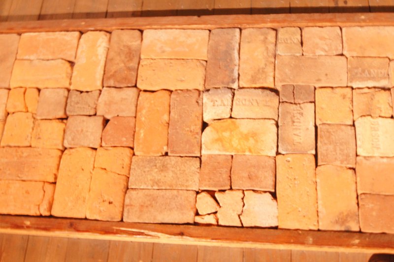
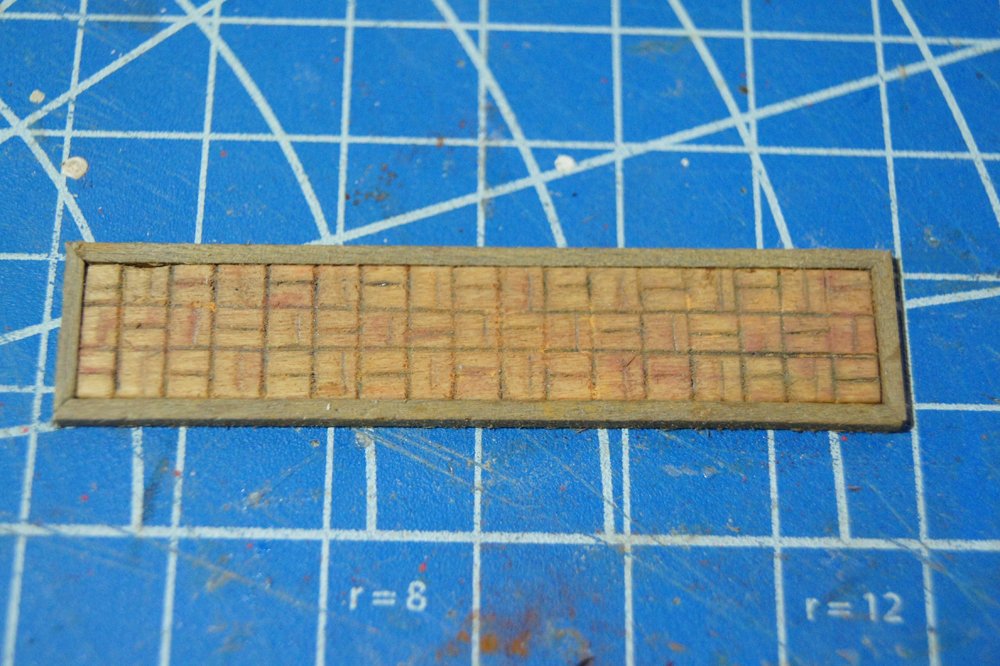
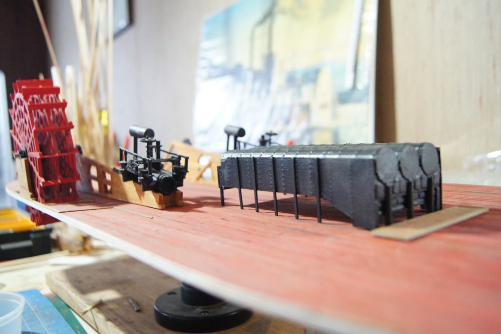
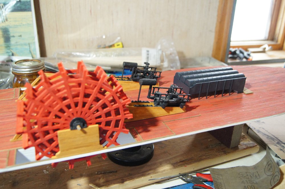
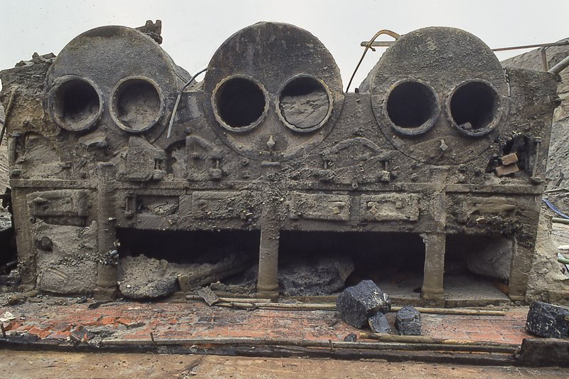
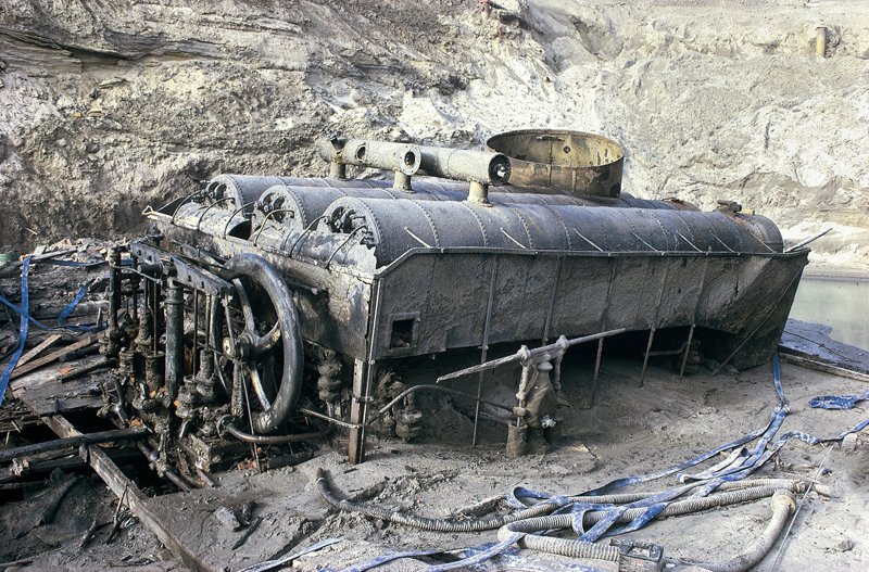
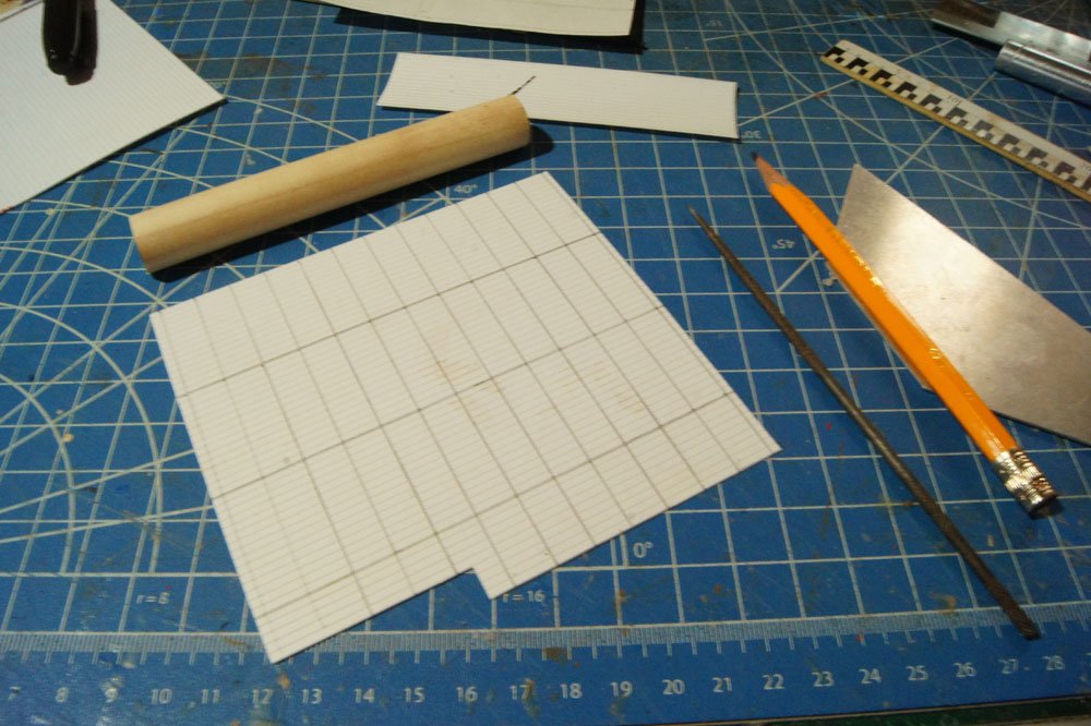
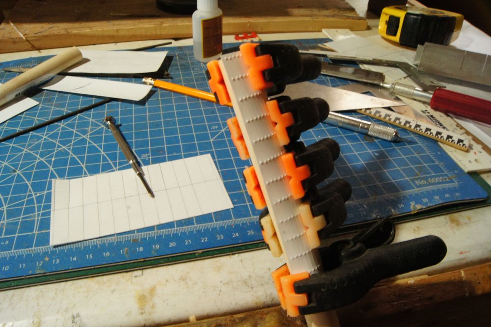
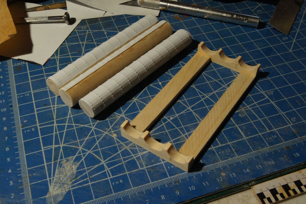
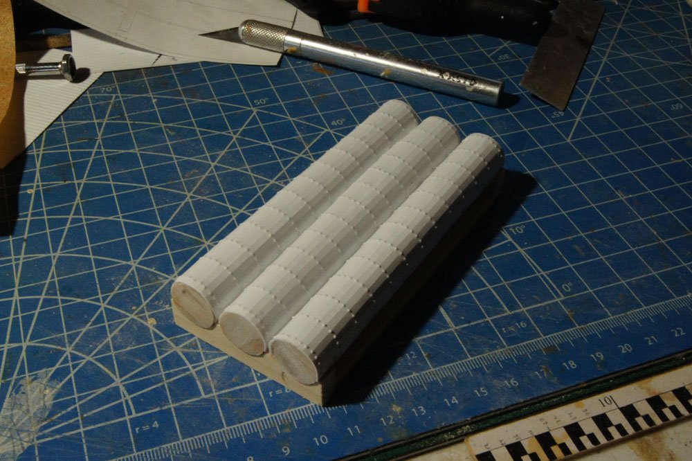
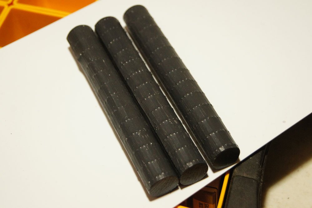
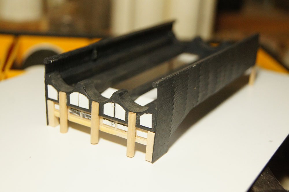
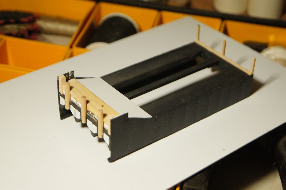
Work has finally commenced on the poor, neglected Arabia. My shoulder is slowly improving with rest; it's still sore but I've been able to cook and do dishes again. Driving my stick-shift truck is probably the most problematic behavior I can't avoid, but since I work at home I only have to do that once a week or so. Most importantly, I can cut, sand, glue, and paint! I decided to tackle the boilers next. See my design thread for a full review of the original components, but below are reposted the two best photos I know of showing the boilers still at the wreck site. The first decision I need to make was how to simulate the rivets joining the roughly 2' wide sheets of iron composing the boiler tubes and the skirting around them. I had already purchased a dowel of the right diameter for the boiler tubes (about 3.5' wide and 24' long). So I dug around in my scrap box and turned up a very thin sheet of scribed styrene originally meant to simulate siding for model railroad buildings. Experimentation showed that the scribing was perfect for allowing the sheets to bend around dowel, so I marked off three pieces necessary to wrap half of each dowel. I did only half because (a) the bottom half won't be seen and (b) this one piece of perfect scrap wasn't big enough to do the rest. Next I experimented with punching divots into the styrene to simulate rivets. I tried a variety of tools, from pointed files to pencils, and finally settled on a small Phillips screwdriver that made nice indentations while being too blunt to go through the material. It was also more ergonomic to use than other options, important since I'd be doing a lot of this. Once I was happy with my method, I carefully measured out 2' increments along the boilers and began punching manually. I think the results look quite good, as seen below. To attach these sheets to the boiler dowels, I laid a line of CA down the middle of each sheet and glued it to the dowel. Once that set, I laid another line of CA along one edge, wrapped and clamped that, then did the other side (see above). This worked nicely, though I had to work quickly to get the clamps set before the CA set. Next I started building a cradle to hold the boiler tubes and support the rest of the boiler structure, as seen below with the finished boilers. Here are the boiler tubes resting in their cradle; you can start to envision the final product. Next, I painted the tubes with the same black I used for the engines. It's a thick Model Shipways paint that does a decent job of blending different materials together and giving a metal-like finish. I'll dull the finish with some pastels. Next, I started expanding the rest of the structure, adding details made of wood and thin styrene to simulate the various furnace doors, ash doors, legs, and other parts of the boiler assembly. I also added sheeting along both sides, using the same rivet-punch technique as the boilers. That's where the boilers stand now. Next, I'll finish adding details and structural elements, finish painting, and weather it with pastels. Then I'll have to decide how much of the detailed piping I want to install, I don't think I can handle all of it, so I'll work out a reasonable simulation. If you go back to the design thread linked above, you'll see what I mean at the stern end of the boilers. Still, I think this looks pretty good for something knocked together from mostly scrap parts, with a sore shoulder. On the finished model, it'll be somewhat buried in the shadows of the main deck, so I don't feel the need to simulate every detail. I'm a big believer in creating the illusion of accuracy rather than counting every rivet. Thanks for sticking with me over the long delay.
- 599 replies
-
- 20
-
-
- sidewheeler
- arabia
- (and 4 more)
-
Exploring the maritime history and geography of Chile
Cathead replied to Cathead's topic in Nautical/Naval History
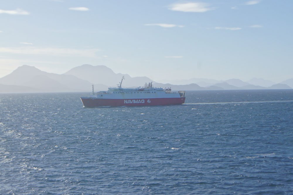
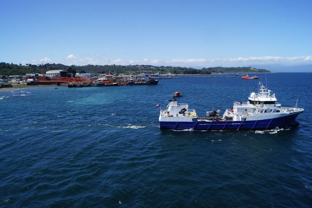
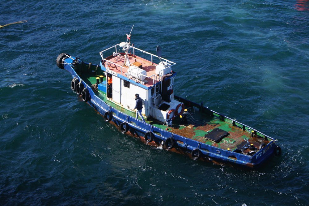
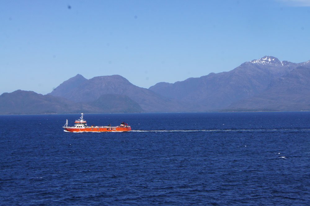
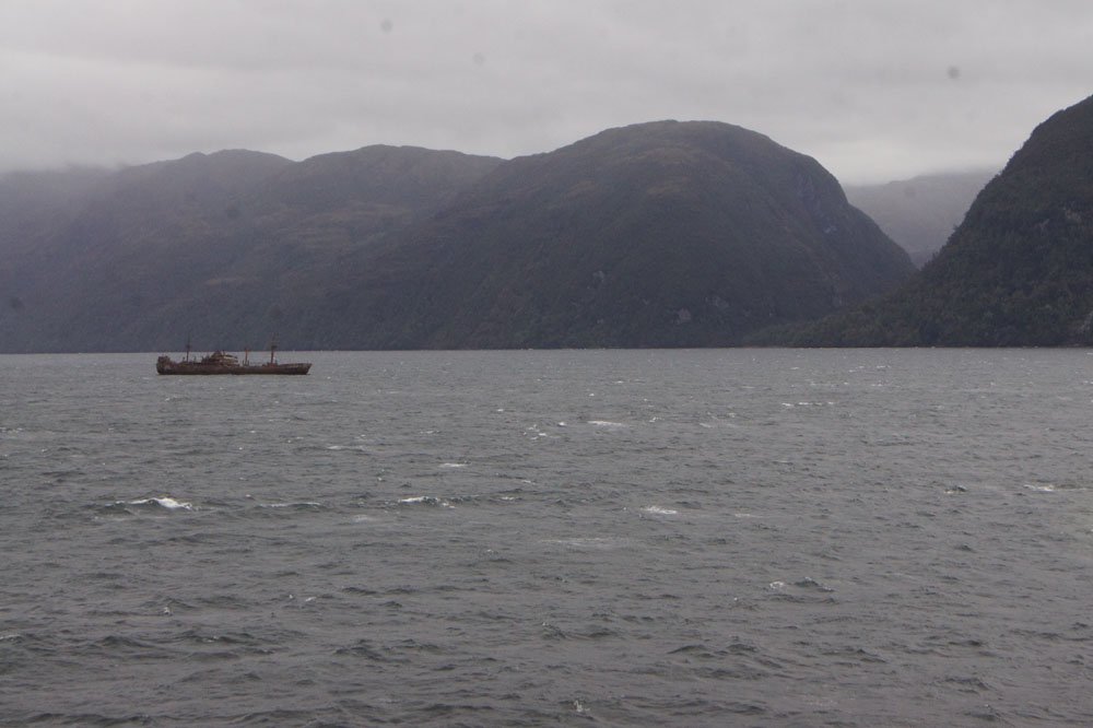
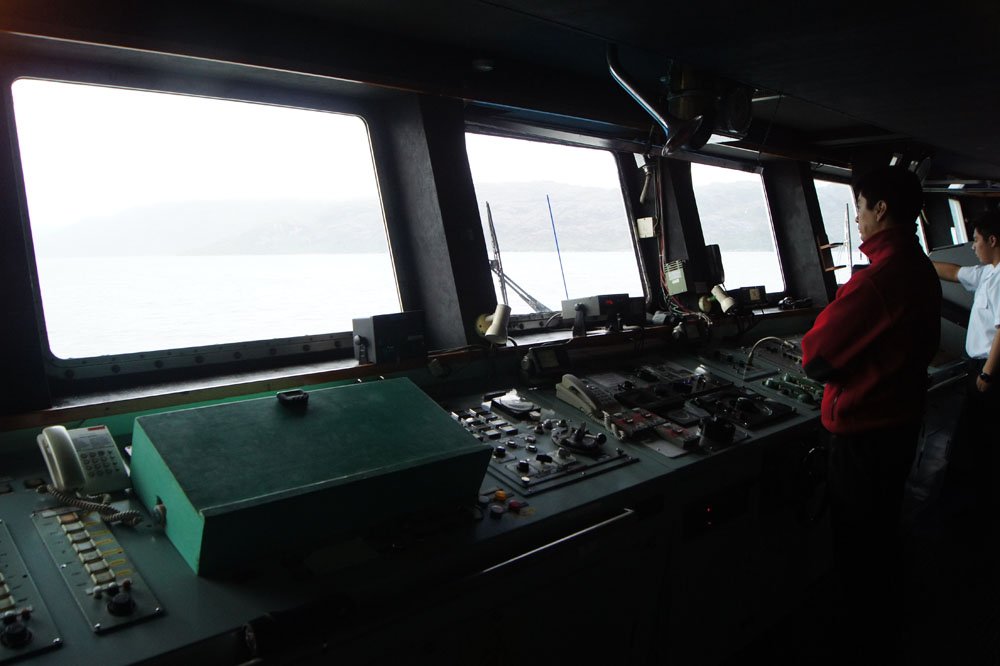
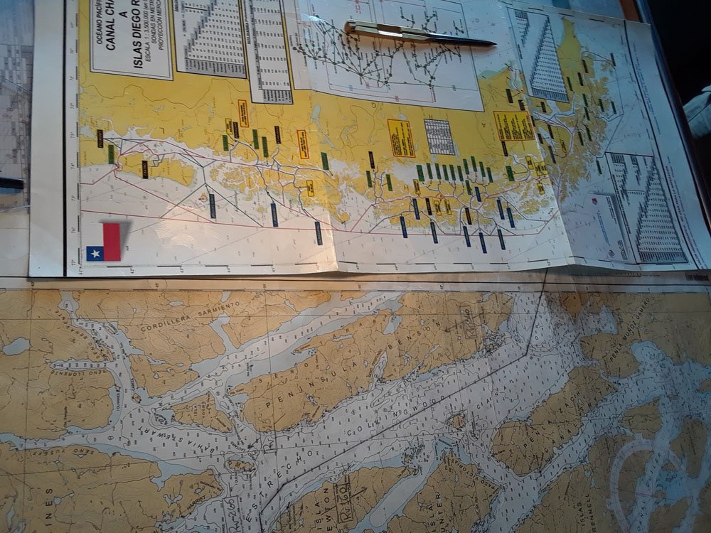
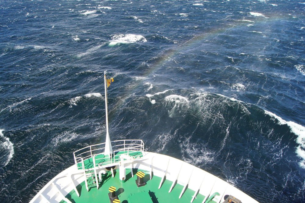
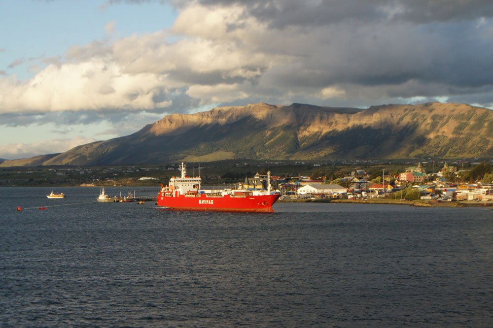
Continuing south, it's time for one of Chile's greatest maritime experiences, the ferry route to Patagonia. South of Puerto Montt, the mainland breaks up into over 1,000 km of islands, fjords, and mountains capped by two major ice sheets. It's not possible to travel to Chilean Patagonia by land unless you cross the Andes into Argentina, but there is a ferry service that runs through the fjordlands to Puerto Natales. Similar to the Alaskan Ferry system (which I've also used), this is a working service whose primary purpose is to serve communities and locals in the region, but which carries tourists as well to balance the books. The voyage takes four days and three nights, all of which are overloaded with scenery, bird-watching, and of course interesting maritime traffic. The Evangelistas was build in 1978 (about my age) and measures about 115x21 m with a draft under 5 m. She takes many hours to load with trucks, trailers, and other cargo, which seasonally can include livestock from Patagonian ranches. Above, you see the stern-loading ramp extending to shore at Puerto Montt. She also carries around 300 passengers (both tourists and regional residents) and 40 crew. A different, but similar Navimag ferry encountered on the voyage gives a rough sense of context. I never got a shot of the Evangelistas, though she's easy to Google if you want to, because we didn't have a chance while boarding and we didn't disembark until after dark (and she sailed the next morning before we got back down to the harbor). Puerto Montt, like Valparaiso, is chock full of interesting shipping. In many ways, visiting Chilean ports felt like time traveling back 70 or 100 years, because there's so much greater diversity in the size and nature of the shipping, and much more cargo handling is done by hand or small crane. Everything from small-medium ocean-going freighters to little flat-bottomed lighters shuttling things all over the harbor; it was a bustle of activity that felt very different from modern US ports with their super-large shipping. I could have spent all day watching this. The Orca Yagan, which is listed online as a Fish Carrier. I assume this means it services the myriad salmon farms spread throughout Chilean Patagonia. I'm not a big fan of fish farming, but this was a very attractive vessel, especially clean and well-kept. This neat little tug was hovering around the ferry, bobbing like a cork in the tiniest waves. We saw a lot of ships of this general type; I have no idea what they are, but most had lots of piping and equipment on their rear decks, suggesting they aren't cargo ships. There's oil and gas exploration in southern Patagonia, but not in the fjordland area, so I don't know what these are. The wreck of a Greek freighter, I believe from the 1950s, deep in a remote Patagonian fjord. It's sitting on solid ground, a sunken hilltop that forms a dangerous reef in the middle of the fjord. We particularly enjoyed being allowed to visit the bridge. They have a modern navigation system shoehorned in at far right, but are clearly comfortable with older methods of navigation. There's a big chart table that has a full set of charts always at the ready, which we enjoyed poring over. Some of these fjords are over 600 m deep, often deeper than they are wide. Patagonian wind earns its reputation. Here, it was screaming from astern and whipping sheets of spray off the water into walls of mist that carried forward like curtains. With the sun at the correct angle, beautiful rainbows arced from the bow. Very few people saw this, as most were huddled indoors. We spent 95% of our time on deck regardless of weather and were rewarded with wonderful experiences like this, as well as all sorts of good birds and other marine life (like the relatively rare Chilean dolphin along with albatrosses and skuas). Arriving in Puerto Natales in southern Chilean Patagonia, we had to wait for this Navimag freighter to clear the one loading dock. Everything was delayed because the wind was too strong to allow safe departure or arrival; we circled the harbor for hours waiting for it to die down with evening. We didn't disembark until after 11pm, dark even in high-latitude summer, but the sunset over the town and harbor gave glorious light. Just astern of the freighter is another patrol boat very similar to the one shown above in Valdivia. In the next installment, we'll head further south to Punta Arenas on the Straights of Magellen, and an amazing museum with full-size replicas of historic ships.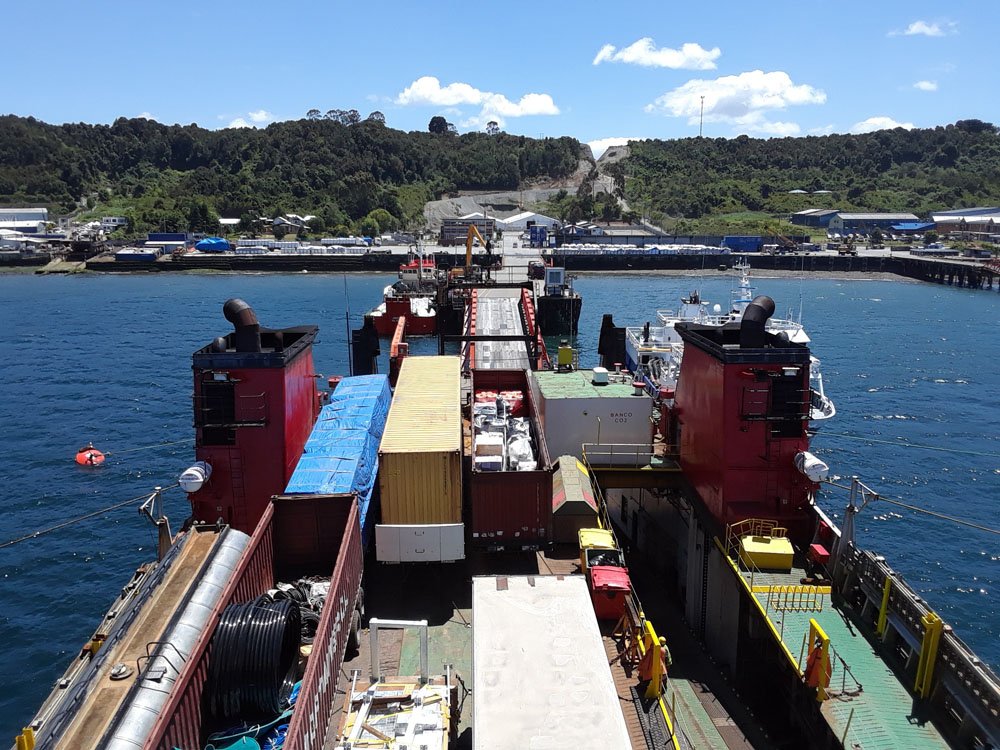
- 16 replies
-
- 10
-
-
Like Bob, I just found your log with your latest update. Your work looks great, I'm sorry I've missed following along so far. It's nice to see another good Chaperon build.
-
Exploring the maritime history and geography of Chile
Cathead replied to Cathead's topic in Nautical/Naval History
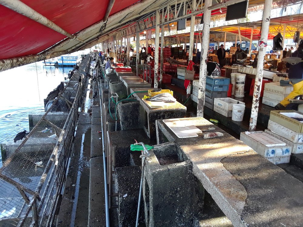
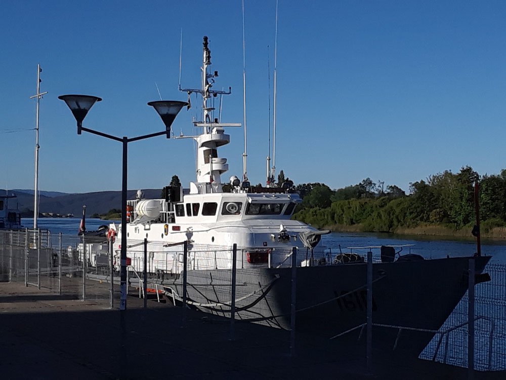
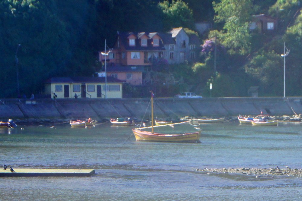
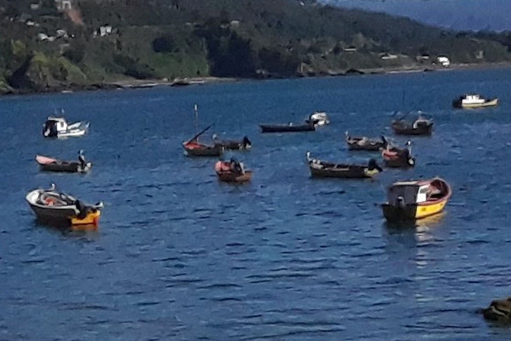
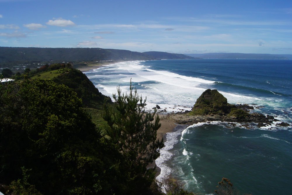
Valdivia has other nautical attractions in addition to the forts. The town's waterfront hosts a variety of tour boats that visit the forts by sea as well as exploring a large nature reserve upriver. The large structure at center is the town's market, where a wonderful mix of fresh produce, cheese, and seafood are sold. The seafood stalls back up to the water, making disposal of offal and other fresh refuse easy. Chile's fresh seafood is one of the country's greatest assets to a visitor. Lest this seem wasteful or polluting, a large population of gulls and sea lions happily takes care of anything going over the side: Among the interesting vessels tied up along the waterfront, we found an old Chilean Navy submarine (open for tours, but not when we were there) and this modern patrol vessel: The region also hosted many interesting fishing boats. Most noticeable were a distinct style of open boat, always painted red and yellow, an example of which I saw in the Valparaiso Museuo Naval. These, however, were often rigged with simple triangular sails. Looking out to sea from the Niebla Fort, I could see a series of these far out with their sails rigged, but my camera wasn't good enough to capture them. Here are two not-so-great photos of the type in harbor: I wanted to learn more about these, but couldn't get clear answers from local fishermen. When I asked what they were called, for example, all I could get was "lancha", which is a generic Spanish word for "launch" or "boat". Online searches have turned up nothing more (not even better photos), and my Spanish isn't good enough to dig deep into historical archives. If/when I return, I'd like to focus on learning more about these; they were the first time I've ever seen sail-based fishing boats in actual operation. They'd make a really interesting modeling project if I could get enough information and better photos. Much of this part of the coast reminded me of northern California or southern Oregon, with rocky headlands separating beaches and isolated fishing villages. A particularly nice location is Curiñanco, to the north, where a nature reserve protects huge old trees on steep slopes above the water and a rocky beach generates beautiful waves and preserves some really interesting bedrock geology (what looked to us like deposits from past tsunamis along this very tectonically active coast).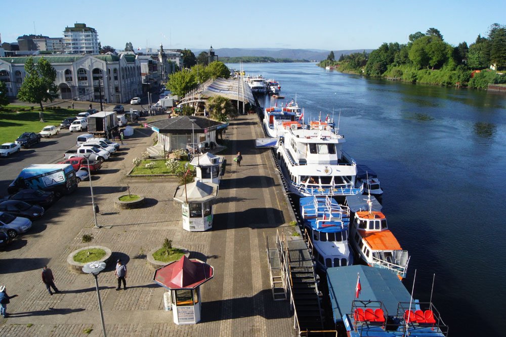
- 16 replies
-
- 12
-
-
What you're doing IS therapy. Most of us benefit from the ability to obsess over something harmless, such as hobbies or sports, or reality can overwhelm us. Having recently visited Valparaiso, where Essex was captured, my interest in following a build of her has been heightened and I'll look forward to learning from this one.
-
Exploring the maritime history and geography of Chile
Cathead replied to Cathead's topic in Nautical/Naval History
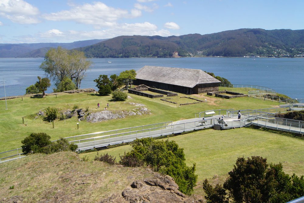
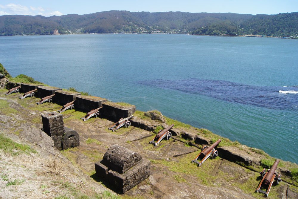
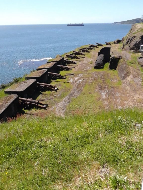
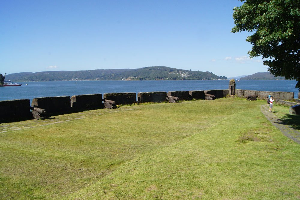
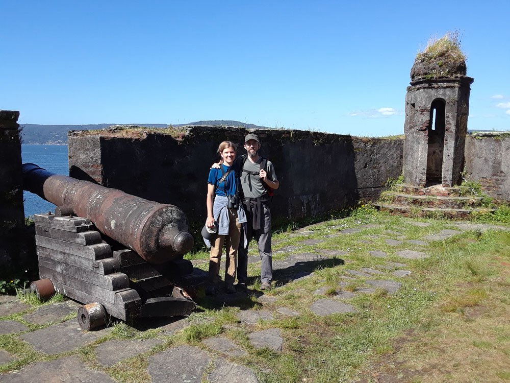
Next up, the southern coastal port of Valdivia, probably my favorite town in Chile. Founded by the Spanish in 1552 on at the junction of several rivers, maybe 10 km upriver from the Pacific Ocean, it's chock full of nautical interest. The site was inhabited long before the Spanish, given its excellent location and abundant natural resources, and played a key role in the Chilean War of Independence. I'm going to cover this in two posts, given how much there is to say and show, and this will still only be a brief summary. Part I: The Valdivian fort system At the river's mouth, the Spanish built a network of coastal forts that made Valdivia the best-defended port in the country. These were upgraded in the late 18th century. Interlocking fields of fire and a narrow navigational channel meant the area was considered impregnable, yet the southern forts were stormed in 1820 by Chilean forces under the command of Lord Thomas Cochrane (model for Patrick O'Brien's Jack Aubrey) during the Chilean War of Independence. This action was fictionalized in the final novel of Bernard Cornwell's excellent Sharpe series. Two of these forts are open to the public today, including the Castillo de Niebla on the north shore, which has excellent interpretive material and sweeping views across the bay: Above, you're looking upriver toward Valdivia (10 km inland). The low ground along the left half of the image was carved out of the bedrock promontory by the Spanish, creating a moat that isolated the rest of the fortress to the right. Even accounting for the fairly soft sandstone here, it's an impressive engineering feat and creates a really unique setting. A reconstructed building surrounded by original foundations. Inside are very well-done interpretive materials including more nice ship models. A view across Corral Bay, aimed a bit farther left (east) than the photo I used in the introductory post to this series. Here you can see two shot furnaces serving the cannons; the magazine was carved out of the bedrock further to the left. Originally, the protective walls (can't remember the right term) were sandstone, but were worn away by centuries of visitors, so they reconstructed some on the left and while the right side remains in its worn-down state. Some of the cannons are originals, too, according to the interpretive materials. Across the bay at center, though it's hard to pick out, is the Castillo de San Sebastián de la Cruz Fort (more commonly called the Corral Fort), the other location open to the public. To the right, the rest of the network's forts spread along south shore out of view (again, see photo in first post). Another view of Niebla's main battery. I liked the juxtaposition of the modern freighter in the background with the old Spanish cannons. In both photos, notice the angled slots carved into the rock floor on both sides of each cannon emplacement. The interpretive materials state that these were for rolling heated shot to the cannon mouths, which makes a certain amount of sense, though to my mind it doesn't explain why you need slots on both sides for every emplacement (I wouldn't think anyone carrying heated shot would run around to the far side). I had initially thought the slots were meant to ensure each cannon stayed in its "lane", given that they perfectly match what would seem to be the maximum traverse and there didn't seem to be any allowance or need for other rigging (as on a warship). Any further input from more knowledgeable folks? I don't know much about fortress design. And here's the opposite view, looking north from the Corral Fort back at Niebla (from the guard tower, count back four cannon emplacements and the Niebla Fort is directly above). This fort is a bit more run down and has no interpretation, but it's a fascinating visit nonetheless. You can tell the Spanish never expected an overland attack here, everything is aimed toward the sea. They assumed the rugged coastline and hills would keep land troops away, but they didn't expect Cochrane's creativity and the Chilean forces' zeal. If I recall correctly, this fort and Niebla never even put up a fight, once the first few forts along the coast had fallen, the Spanish garrisons here up and fled. In their defense, this was a godforsaken posting at the end of the world, the Spanish empire was reeling, and there wasn't a lot of reason to die here. And here are the Catheads centuries later. I thought it was interesting that all the cannons here were on naval-type carriages, while all the cannons at Niebla were on army-style carriages. None of the interpretive materials went into detail on such things, so it's not clear if the carriages are meant to represent original forms or are somewhat random. Note that here, there were no slots around the gun emplacements, which could have several explanations. One, I didn't see any shot furnaces here, which I thought was odd, so if the Niebla slots were primarily for shot that would fit. Two, did this carriage design recoil sideways less than the ones at Niebla and/or have more rigging, so didn't need guidance slots? I don't know. It's interesting that here the ground is paved in rough stone, as opposed to the natural sandstone surface at Niebla. Lots of differences for forts so close to each other and from the same era. In the next post, I'll leave the forts behind and explore some other interesting aspects of the Valdivia era. Thanks for reading. UPDATE: Just realized I completely forgot that there's a third fort you can visit, on the Isla Mancera that sits in the bay just upstream of Niebla. We didn't get there because we ran out of time doing the first two, and boats to the island run less frequently than boats across the bay between Niebla and Corral. But anyone visiting should certainly try to do all three.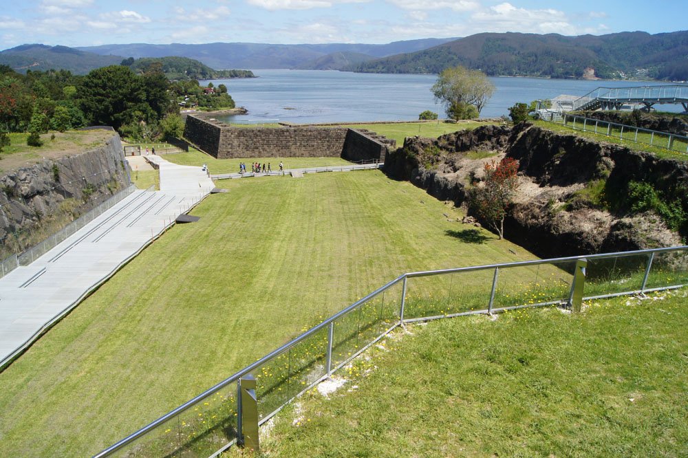
- 16 replies
-
- 11
-
-
Woohoo! Great news all around. Cheer up, a nicely packed train won't give you room to drop it! Congratulations on recovery and what sounds like a lovely holiday.
-
Steamboats and other rivercraft - general discussion
Cathead replied to Cathead's topic in Nautical/Naval History
Good stuff, that's really fascinating. Cool how these boats were simultaneously unique and yet developed some of the same approaches as other regions (like relying on stern wheels in tight or debris-prone areas). I love that last centerwheel one, reminds me of a similar design that operated as a ferry on the Missouri River at St. Joseph, MO in the 1850s.- 281 replies
-
- 2
-
-
- Steamboats
- riverboats
- (and 3 more)
-
Exploring the maritime history and geography of Chile
Cathead replied to Cathead's topic in Nautical/Naval History
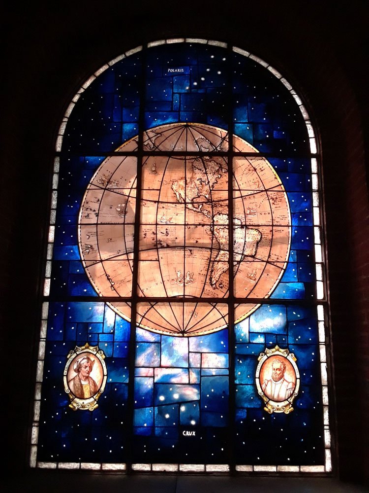
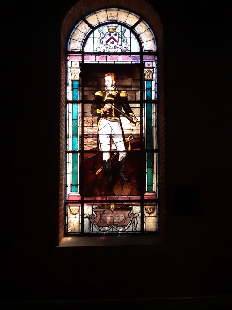
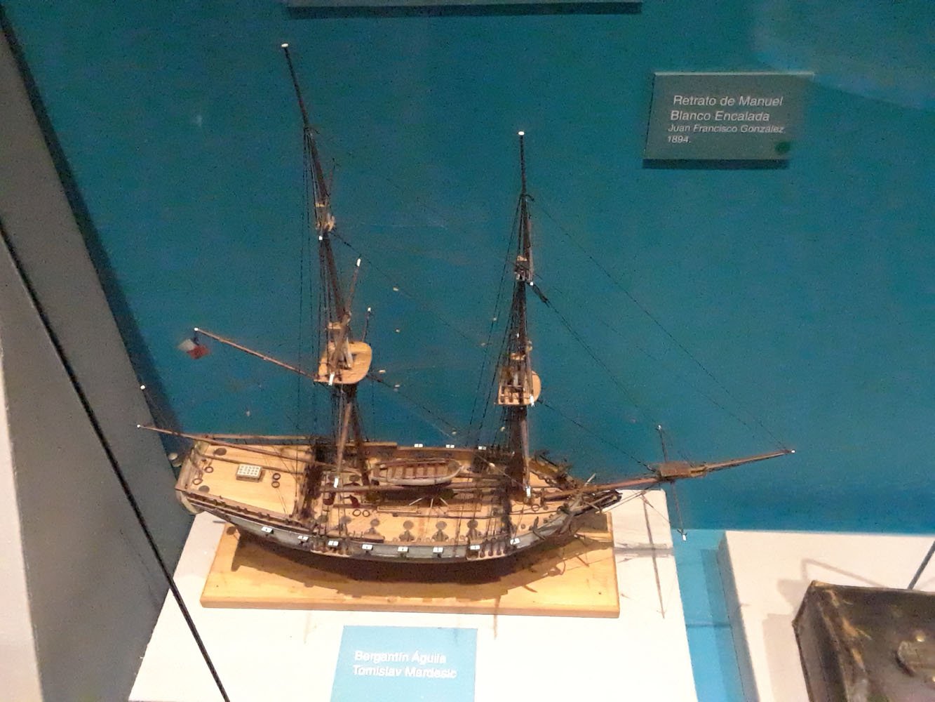
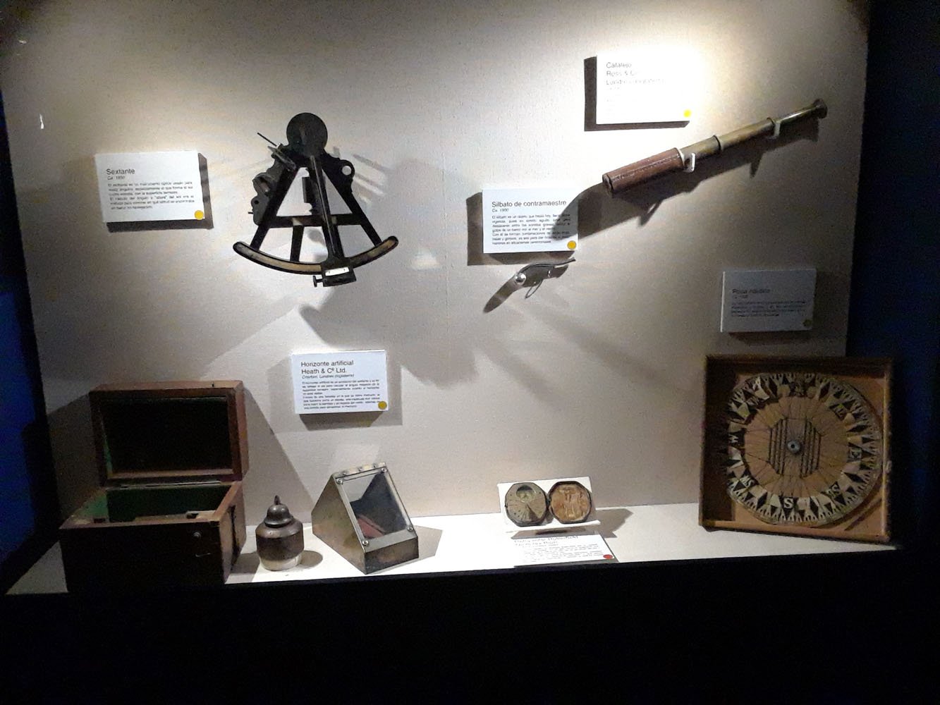
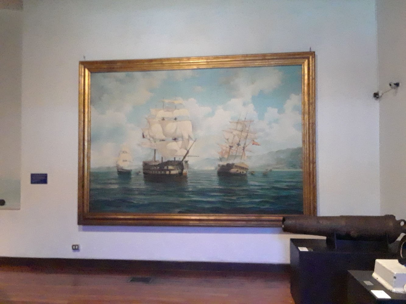
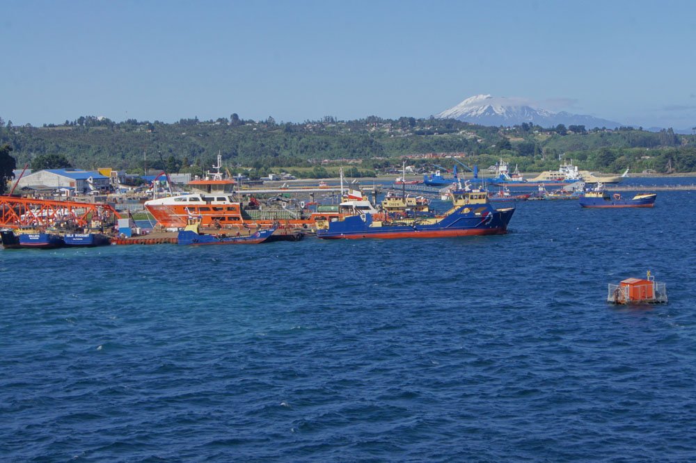
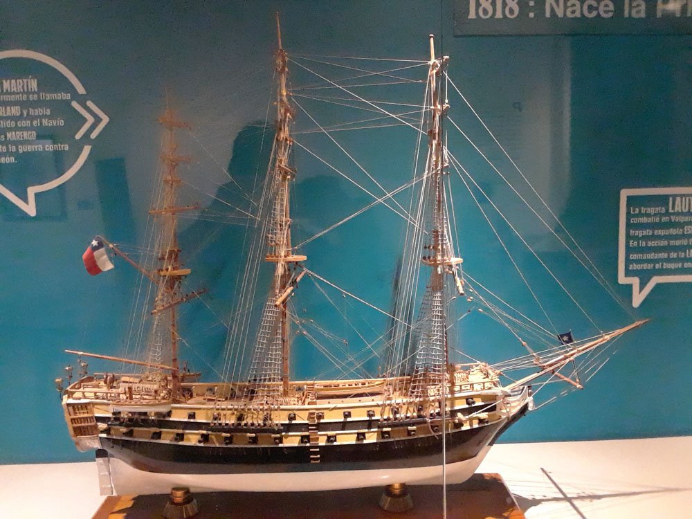
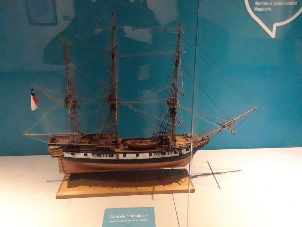
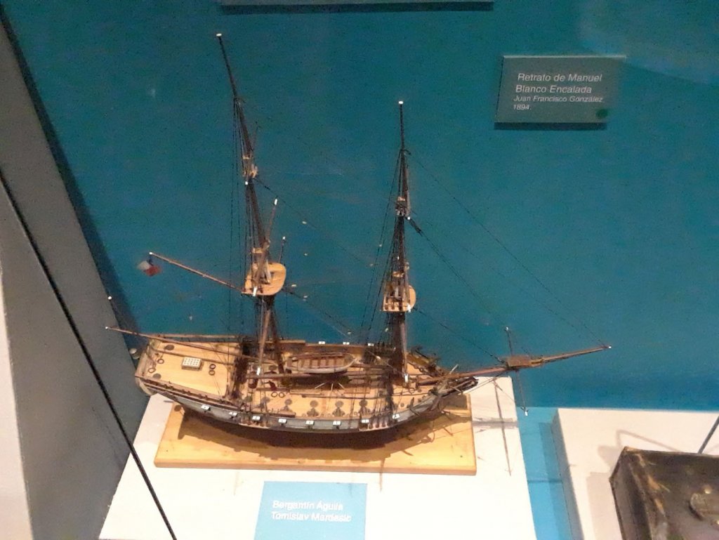
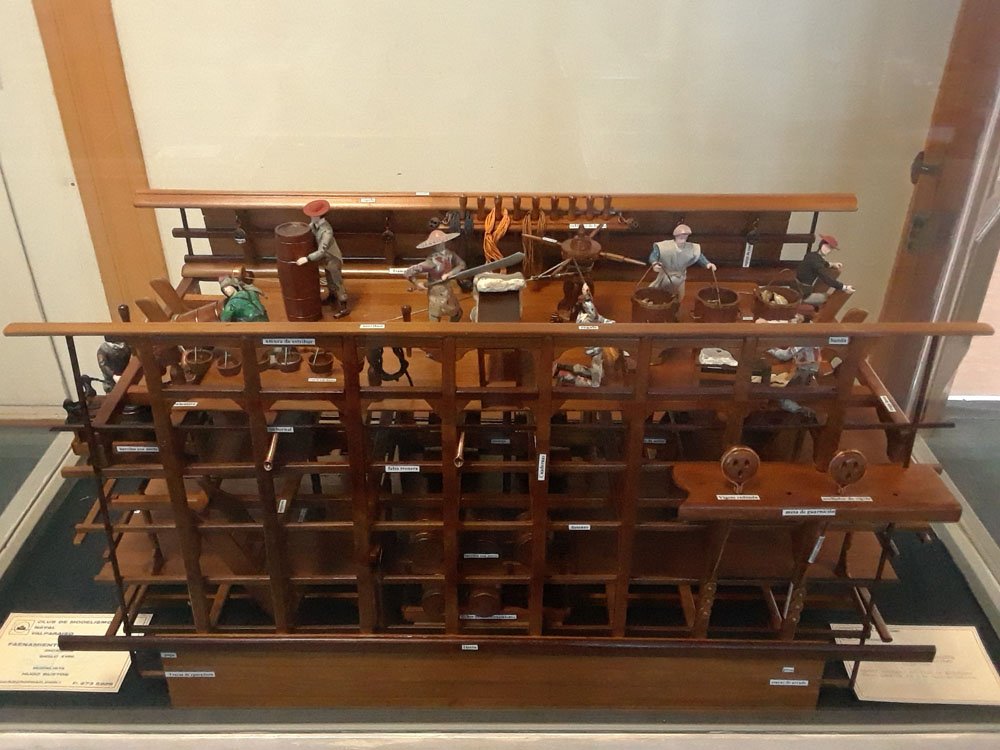
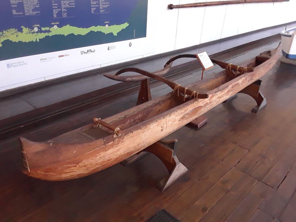
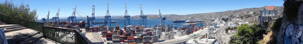
A major highlight of Valparaiso (Chile's main port) is the fantastic Museo Naval, which chronicles the country's maritime history in a beautiful building that, as I recall, used to be their Naval Academy. In classic Spanish style, it consists of a multi-level structure wrapped around a central courtyard with rooms on both floors dedicated to different themes: Hiding at the back is what's labelled as the last-built wooden fishing boat of a specifically Chilean design. I somehow failed to get a better photo of this, which I deeply regretted once I started seeing many of these still in use further south but couldn't get as close. Just out of the photo to the right is one of the Fénix capsules developed by the Chilean Navy and NASA to rescue the miners trapped by the world-famous 2010 Copiapó mining accident. This was really interesting to examine, and I enjoyed watching a small boy playing in it. One of the first rooms features a set of beautiful stained-glass windows made for the museum. Two depict a maritime globe, and three depict heroes of Chilean naval history. The photo above is of Lord Thomas Cochrane, likely of particular interest to many readers here. There are many displays of nautical artifacts; I found these particularly fun. A HUGE painting depicts a naval victory over the Spanish during the War of Independence. There are also many, many interesting ship models, of which I focused my photography on those from the War of Independence era (of most personal interest). Follow the link to learn more about their origins (photos below). The battleship San Martin The corvette Chacabuco The frigate Lautaro. Lautaro was a famous indigenous leader in Chile from the 1500s who led the Mapuche resistance against the Spanish. Interestingly, the Mapuche maintained their independence throughout the Spanish era and well into modern Chilean history, a near-unique achievement in the New World. The brigantine Araucano (an older Spanish word for the Mapuche, which appears in various forms all over Chile). The brigantine Aguila (Eagle). A separate room feature 20+ models from the Valparaiso modelling club. I couldn't photograph them all, but thought this cross-sectional diorama of a Spanish whaling vessel was particularly interesting as I've only ever thought about the English and American kinds. A Rapa Nui canoe from the now-Chilean territory now known as Easter Island. We would find more examples of indigenous craft elsewhere, but this was the only one here. Finally, a broader panorama of the Valparaiso waterfront that captures its diversity and visual interest, taken near the entrance to the museum. There's so much more I didn't share, including other maps, photos, drawings, paintings, articles, and displays dealing with fishing, exploration, recreational sailing, and so on. We spent hours there without getting bored, and I can't recommend it enough if you're lucky enough to get here. I left out the photo of the huge Esmerelda model shown in the first post of this series, but it and its companion Huascar are also fantastic.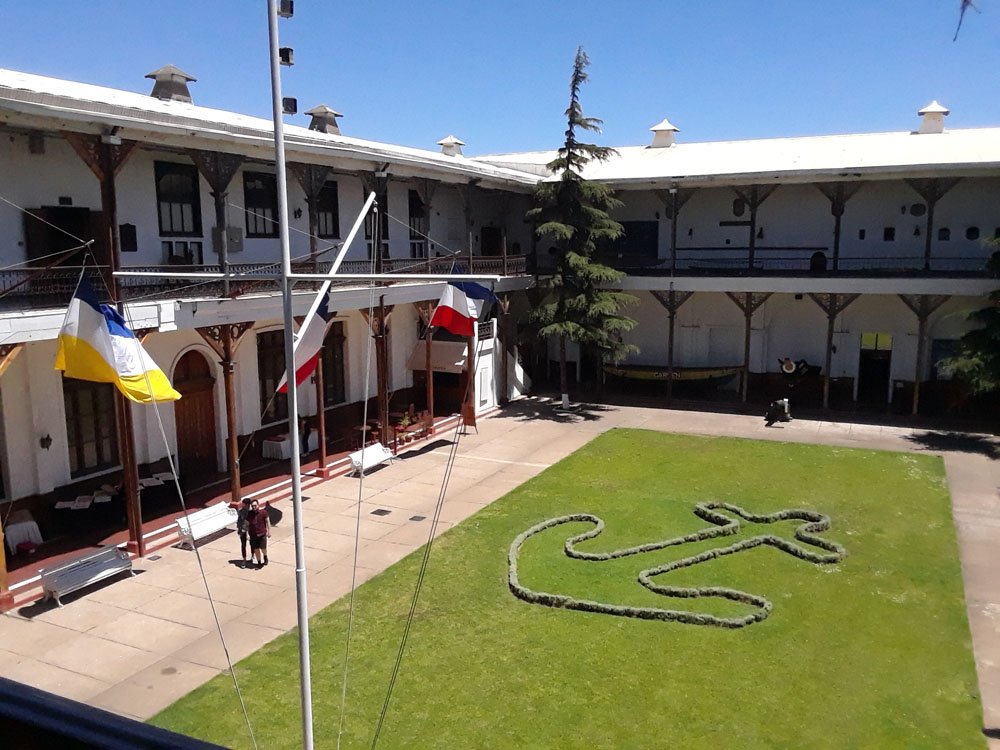


- 16 replies
-
- 15
-
-
Hey, Mark, sorry if my response came across as snarky toward you. Any bitterness there came from my disgust with bipartisan failures in health care, not your reasonable suggestion. Don't need to go any further down that road. For now it's just rest and see; I give it an 80% likelihood of being ok in a few weeks with no more than heating pads, occasional Advil, and thankfulness that I already split this year's firewood stock (I use a maul, not a power splitter). I need time to plan out the superstructure properly anyway and work out my next wood order.
- 599 replies
-
- 5
-
-
- sidewheeler
- arabia
- (and 4 more)
-
Hah, Mark, you're funny. This is the US we're talking about, we have a $13,000 deductible and very limited access to affordable "medical types". There's no way I'm going for medical advice unless this gets MUCH worse. It takes a lot of pain before I'll start spending my hard-earned, self-employed money funding doctors' and health insurance executives' lifestyles. Plus our insurance company will change on January 1st due to more brilliance in the American medical system, so if I go in now I'm going to end up fighting with two difference insurance companies. Much better to just wait two weeks and see what happens; if it isn't healing on its own by then, at least I'll only be dealing with the 2019 company.
- 599 replies
-
- 5
-
-
- sidewheeler
- arabia
- (and 4 more)
-
Exploring the maritime history and geography of Chile
Cathead replied to Cathead's topic in Nautical/Naval History
Yeah, I was referring to areas further south like Chillan and Concepcion with regard to the earthquake. Just mean that Chilean cities have rebuilt from a variety of disasters. Sorry for the unclear phrasing.