


G.L.
-
Posts
1,553 -
Joined
-
Last visited
Content Type
Profiles
Forums
Gallery
Events
Posts posted by G.L.
-
-
This has really become a beautiful model. My sincere congratulations. I look forward to your next project.
-
-
4 hours ago, michael mott said:
Hello Geert I too missed the last part of your build, Wonderful work and the finished model is a nice reminder of the working vessels that supplied some of the food in past times. It is nice to see all the little details that you have been able to include, well done all round.
I will now go look at the gallery.
Michael
Thanks, Michael
-
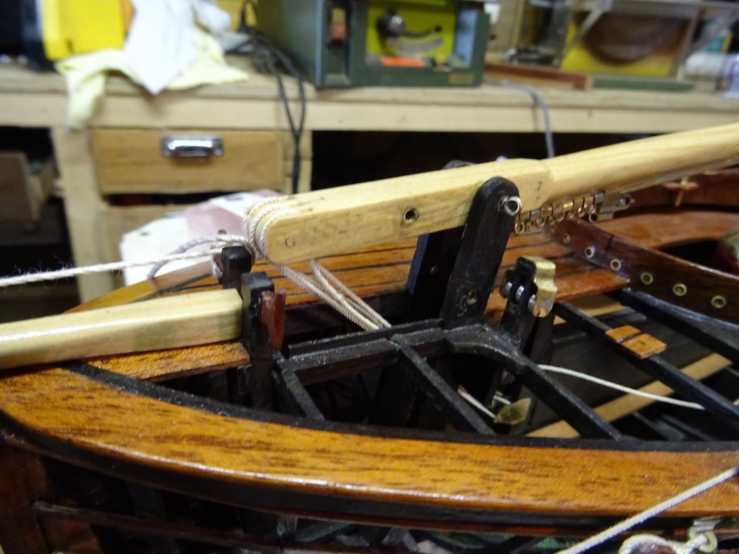
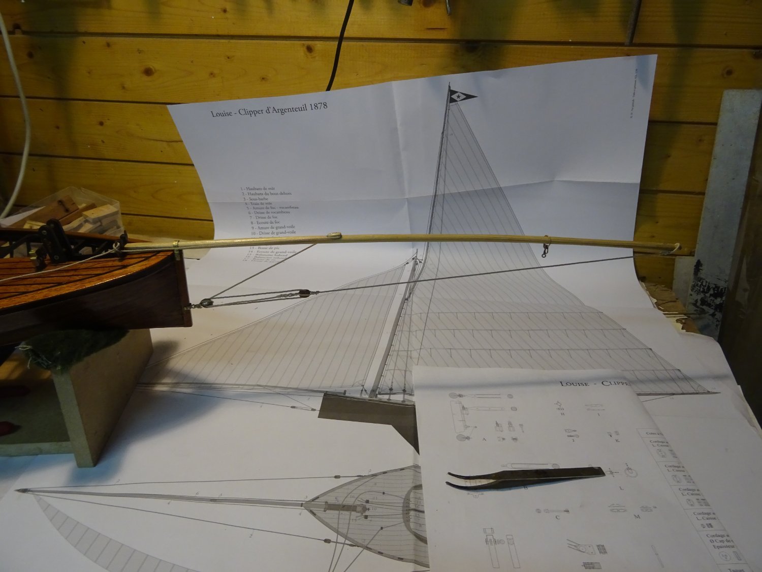
6. Gunter
The clipper d'Argenteuil is rigged with a Houari sail, so the gaff is very steep. I believe the correct English term is 'gunter'.
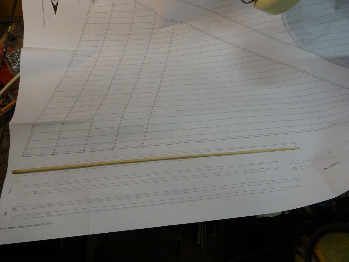
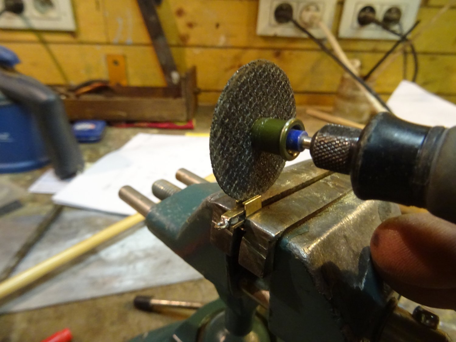
The gunter is also lifted along the mast rail. The gooseneck of the gunter fits in a special slug on top of the sail slugs. Making this slug correctly and in detail is a bit beyond my metal skills. I still managed to make something that didn't differ noticeably from what it should be.
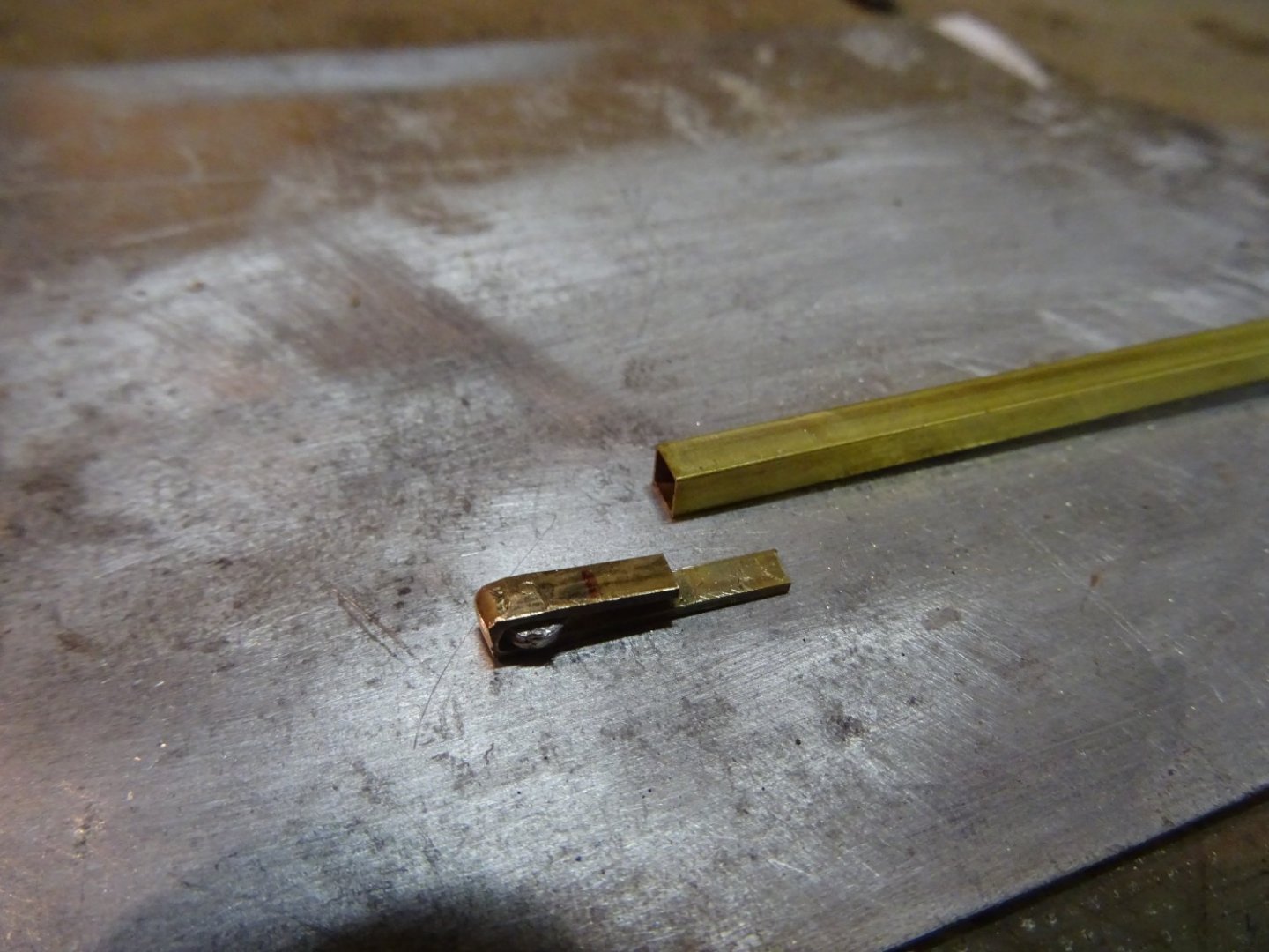

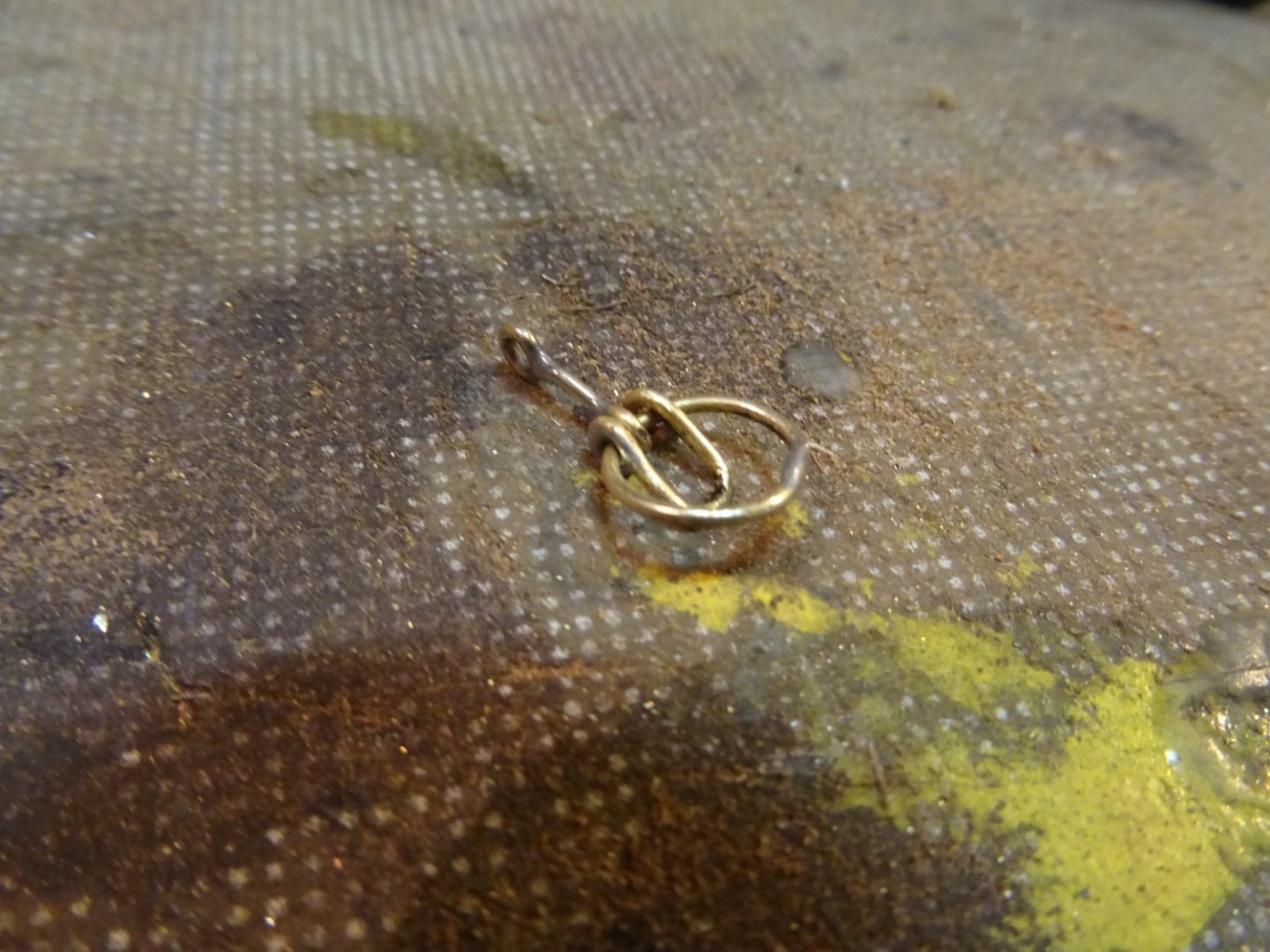
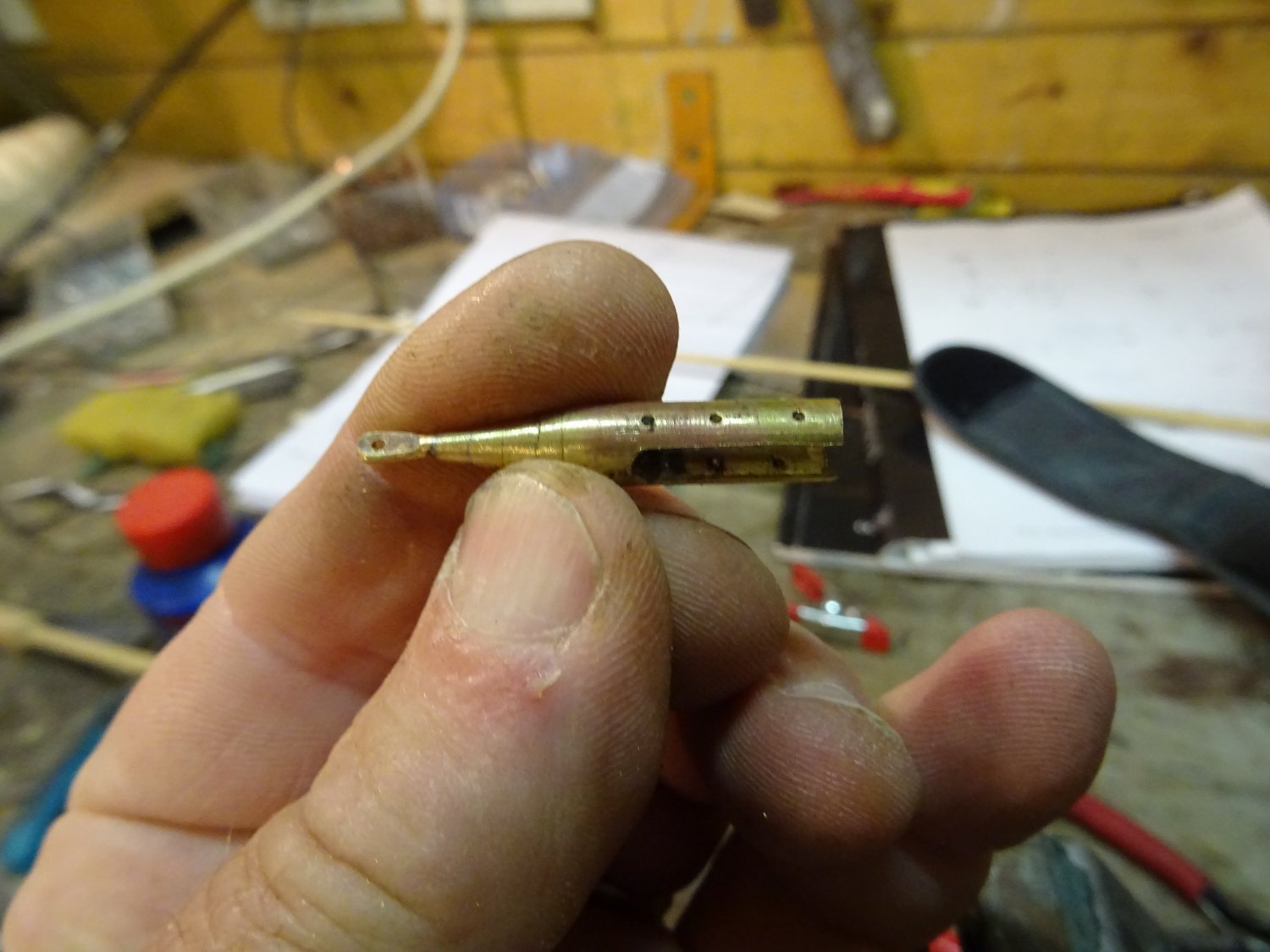
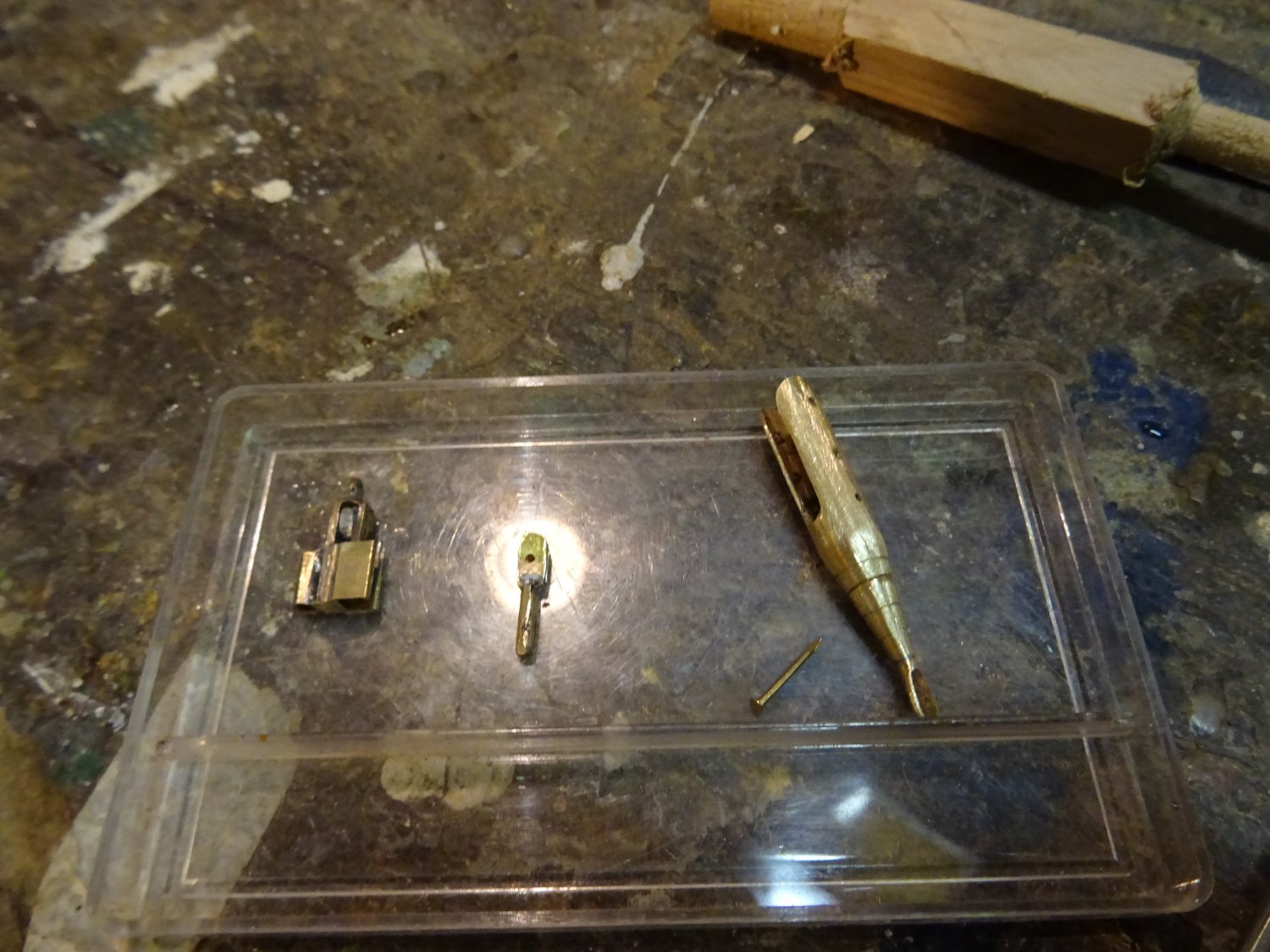
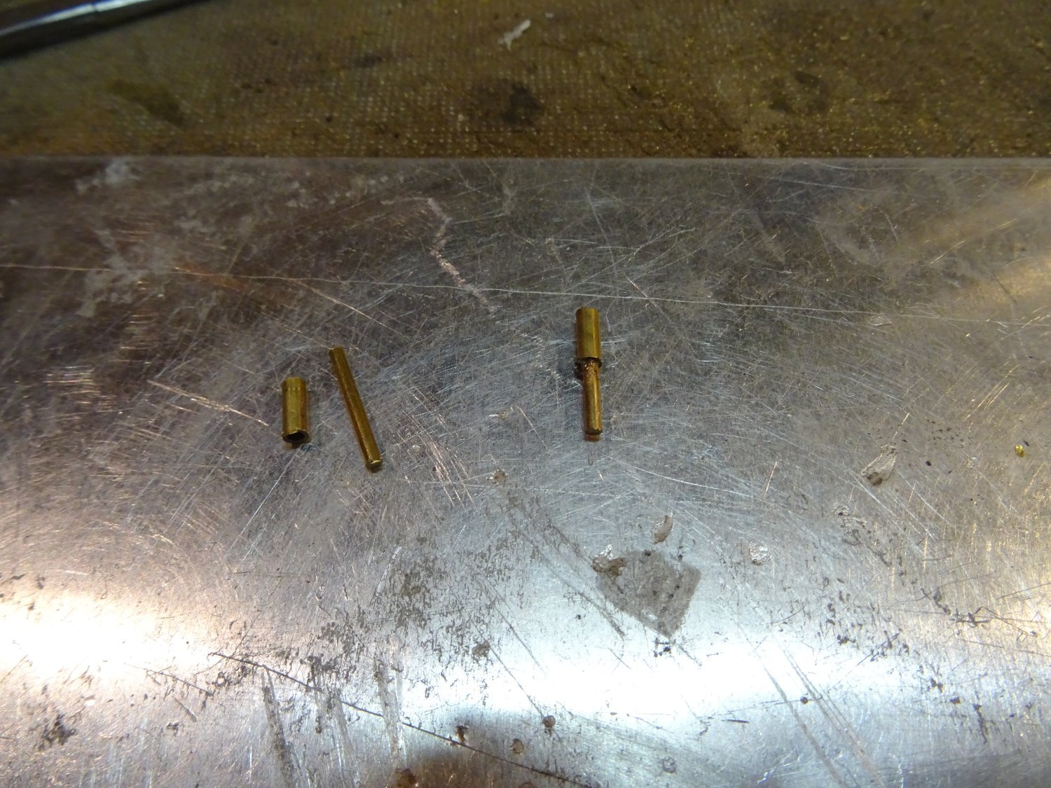
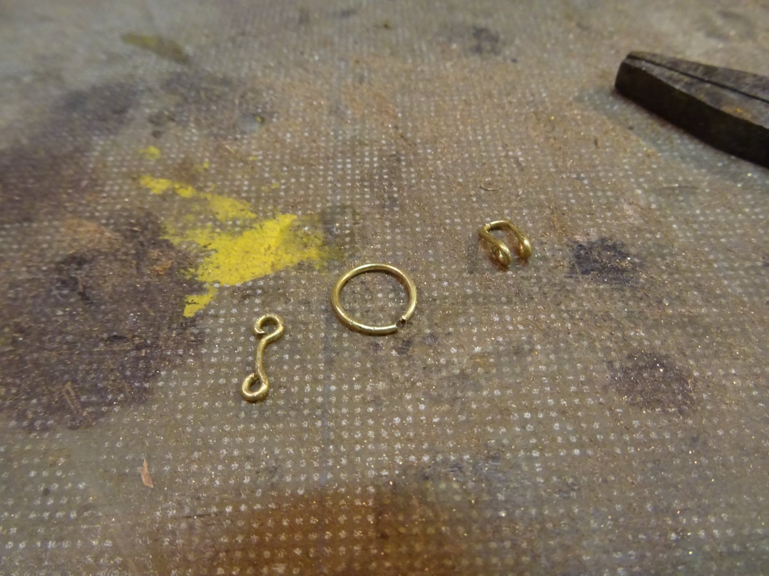
To make the gooseneck I use some telescopic brass tubes that I solder together.
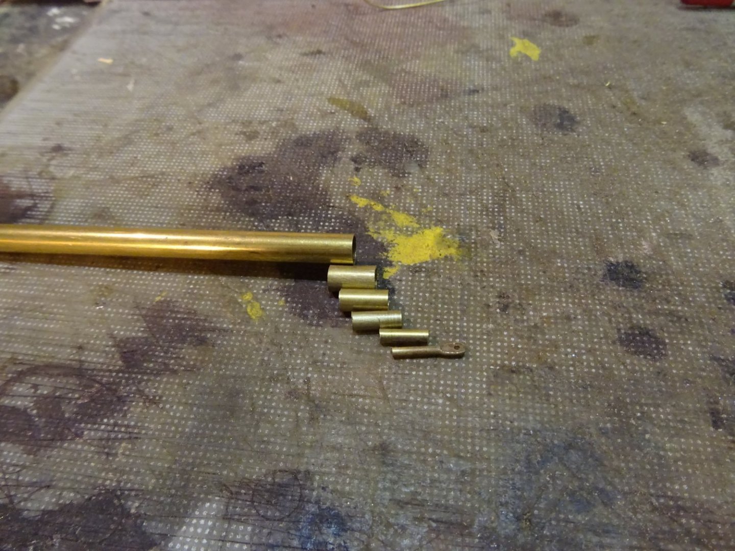
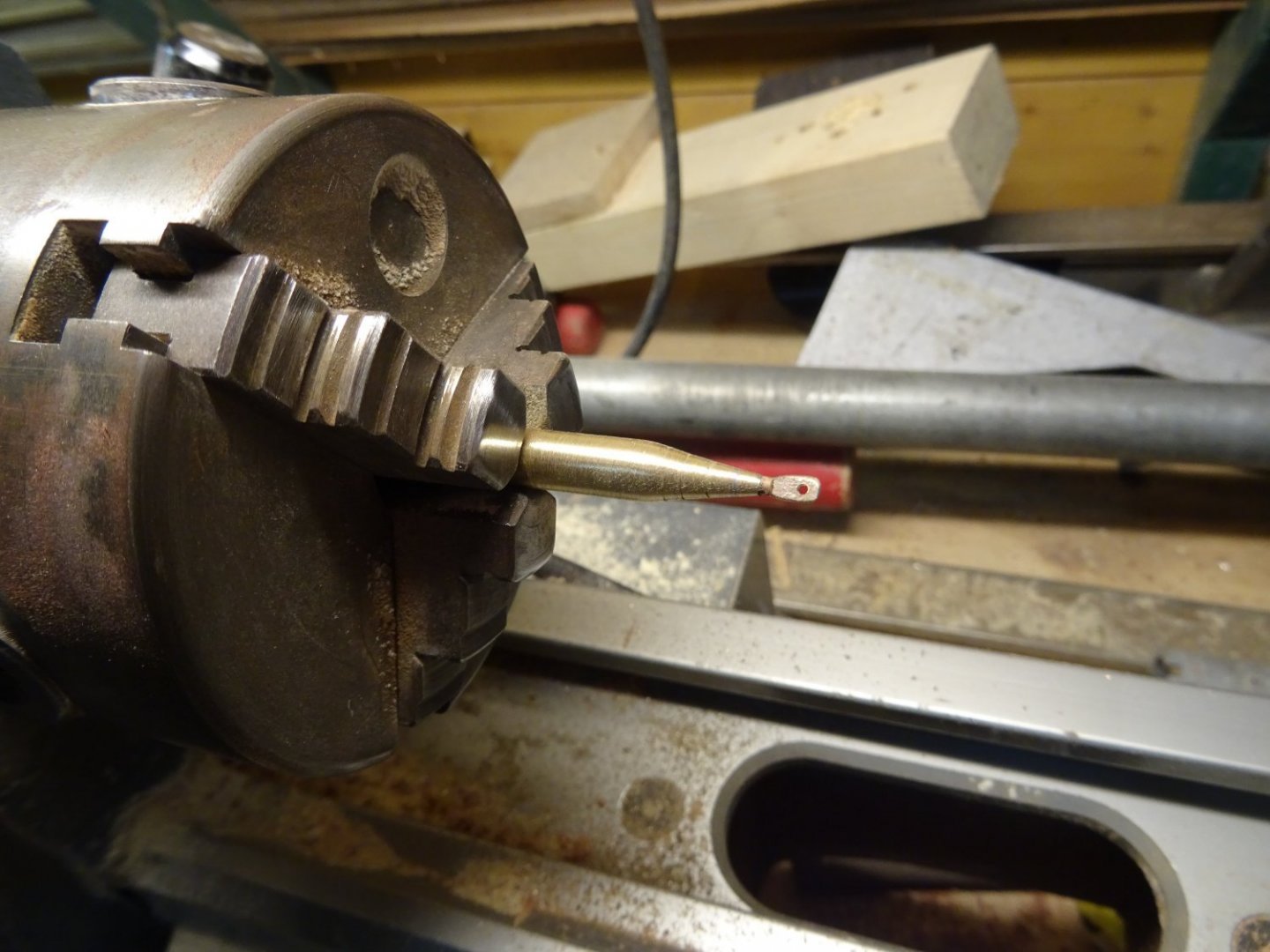
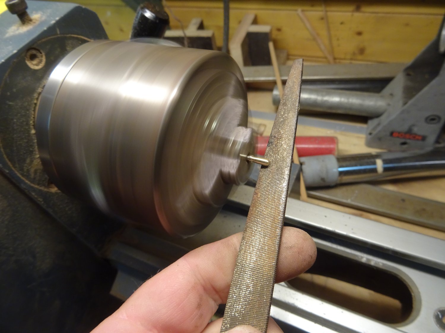
I then file them conically or the lathe.
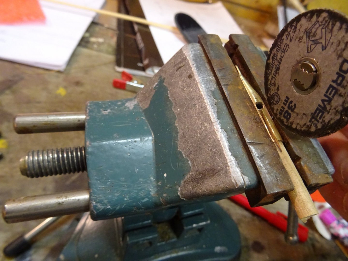
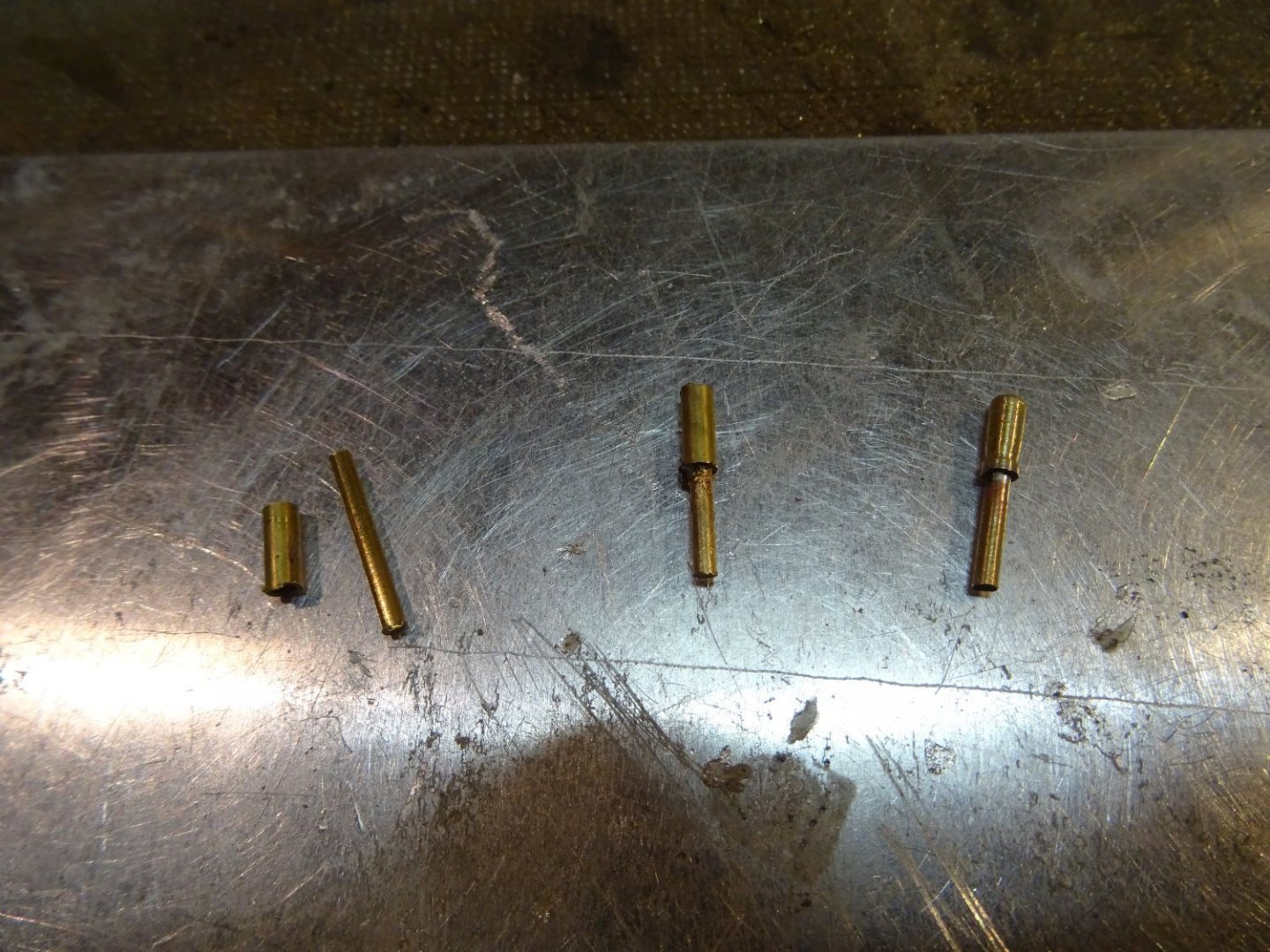
There is a slit at the top and bottom. Sawing the slot.
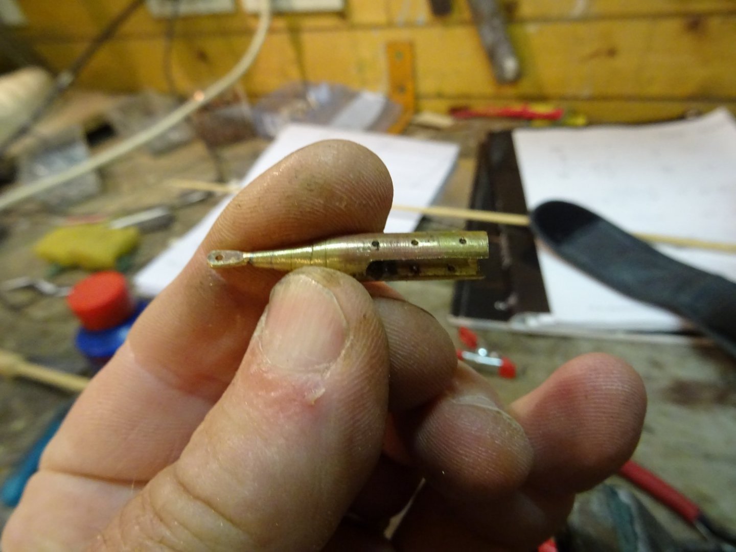
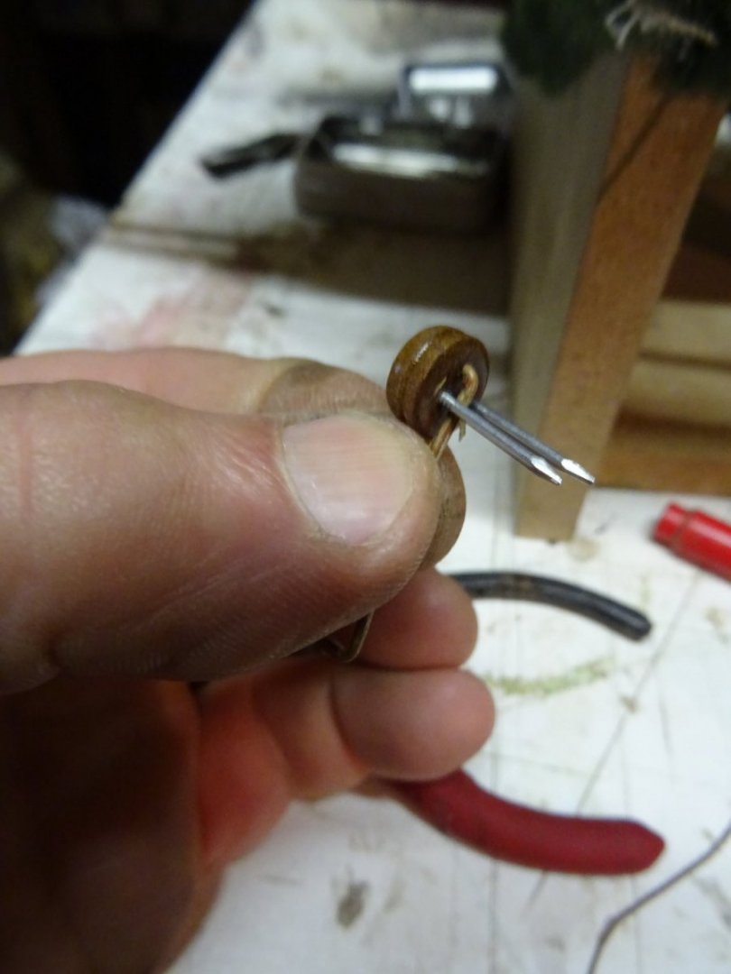
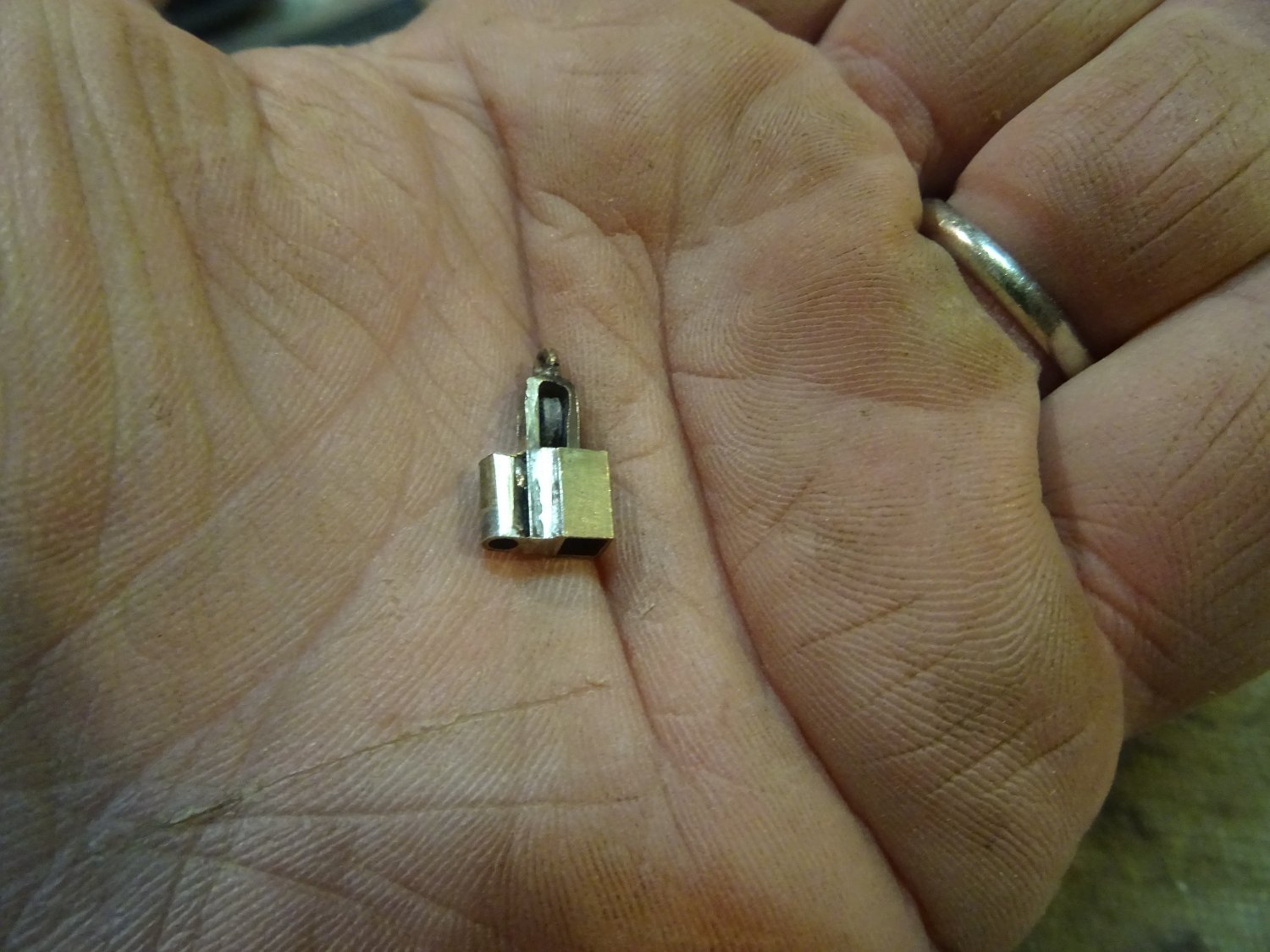
Everything cleaned up.
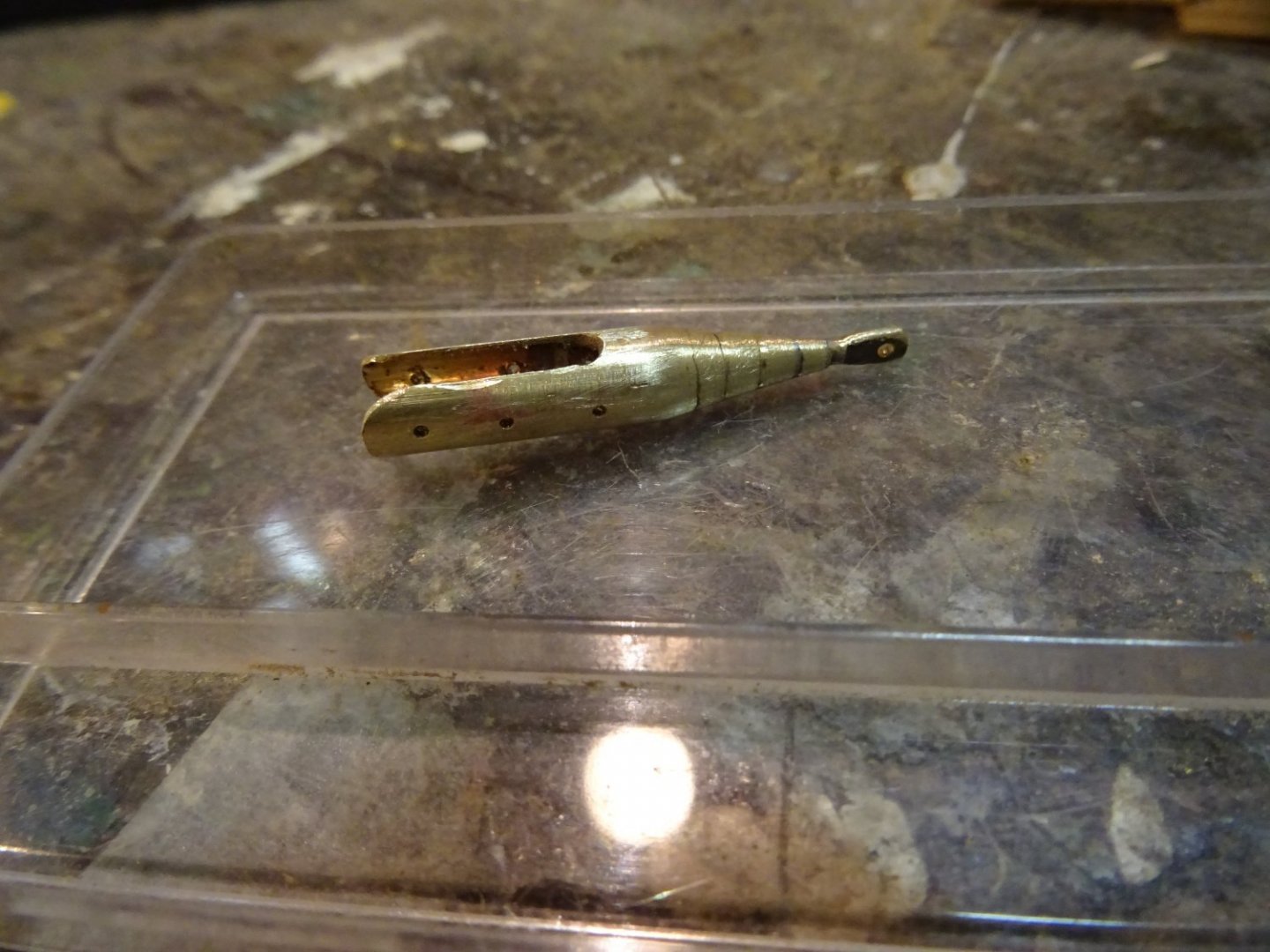
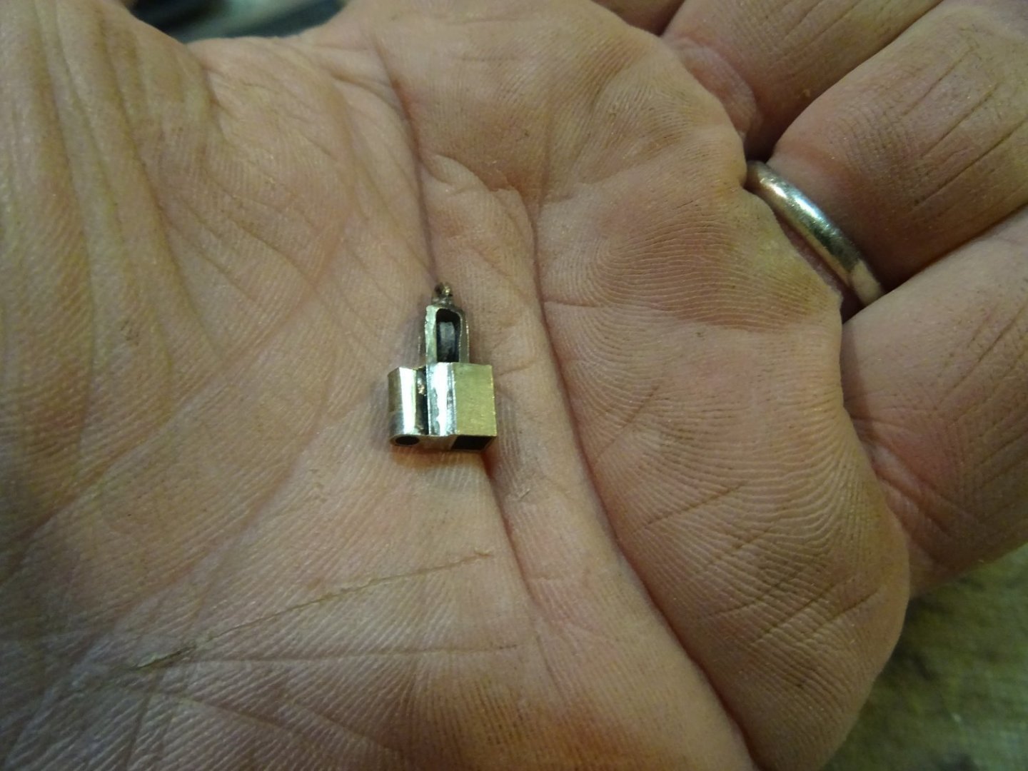
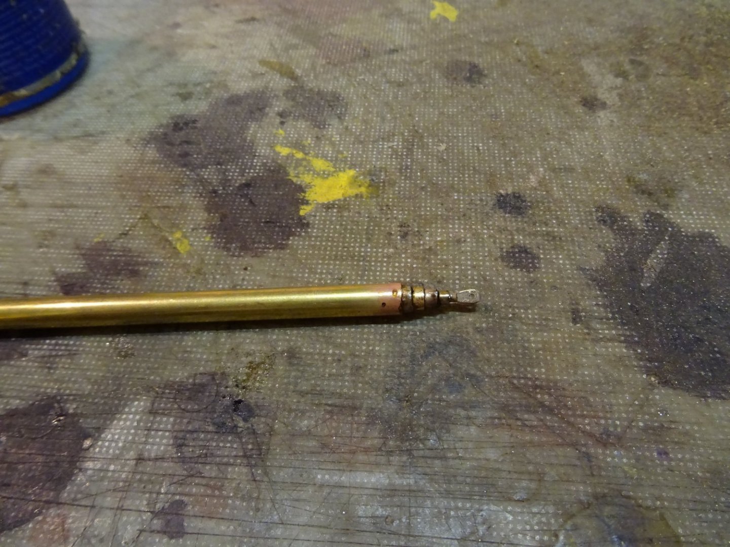
All the parts of the gunter goose neck.

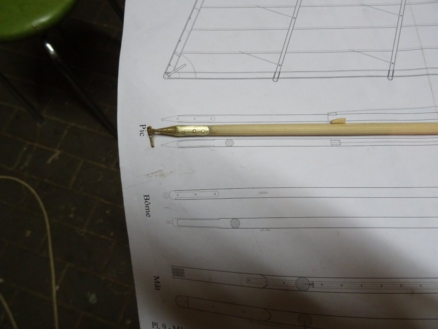
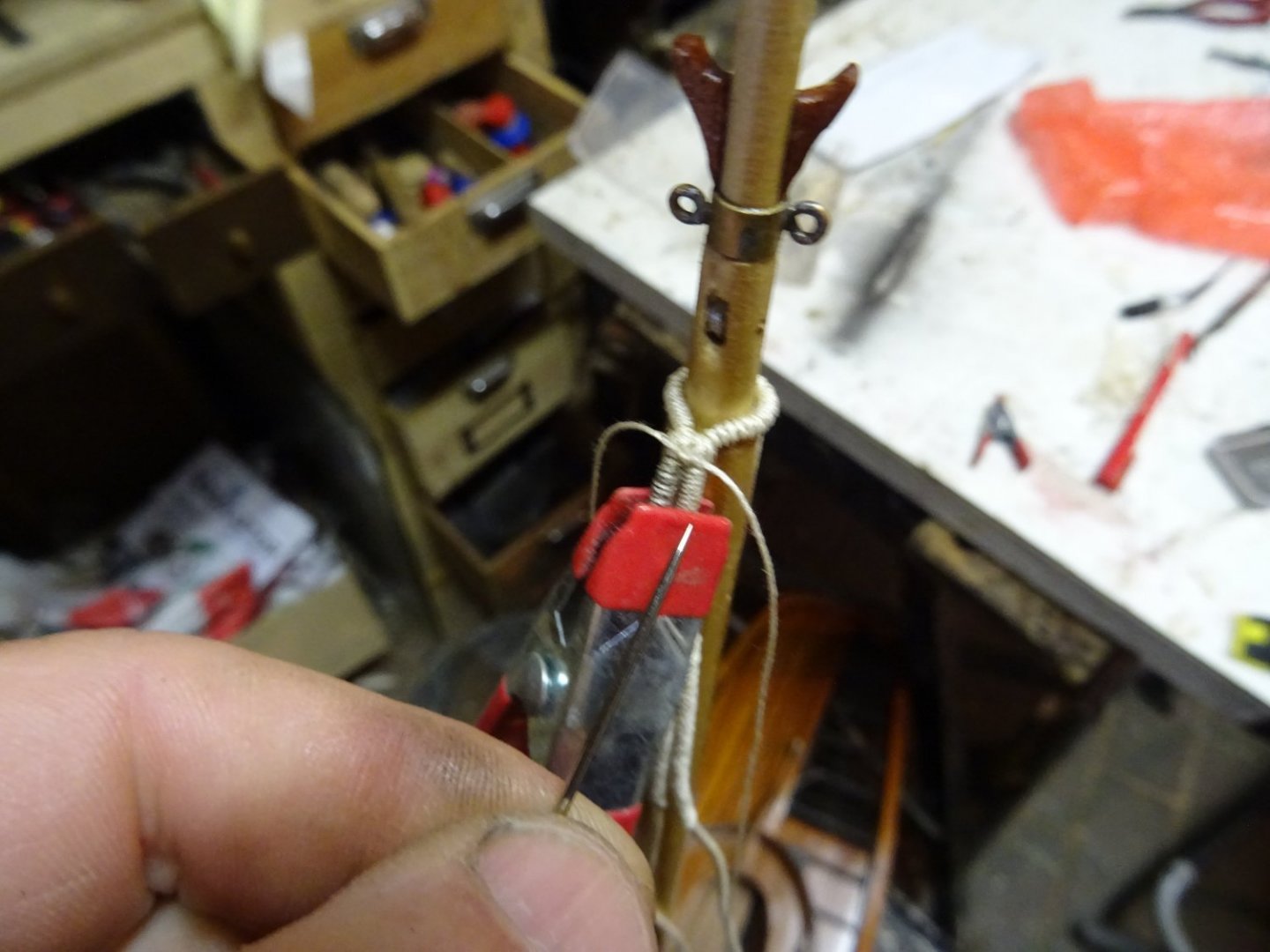
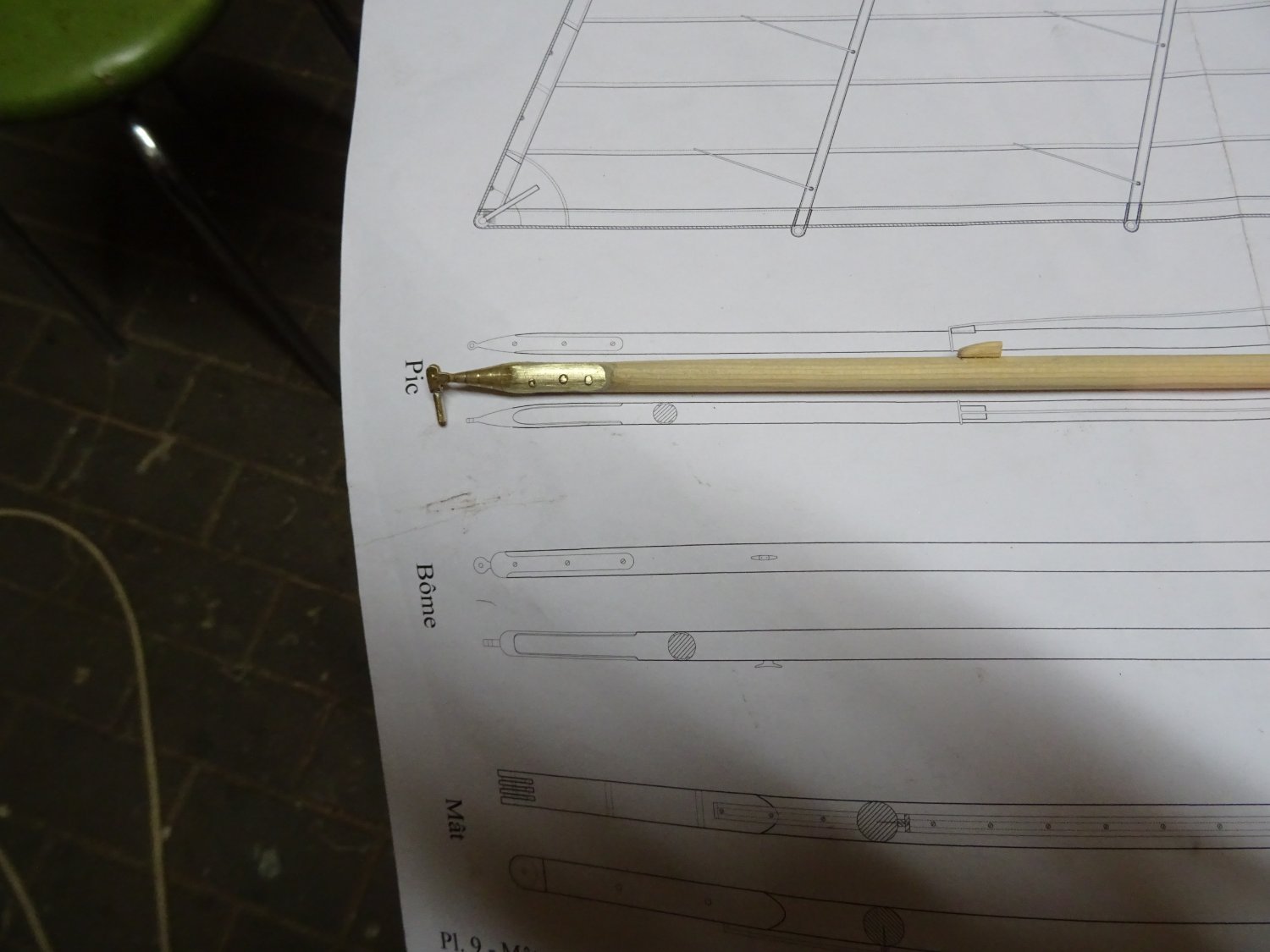
Goose neck on the gunter.
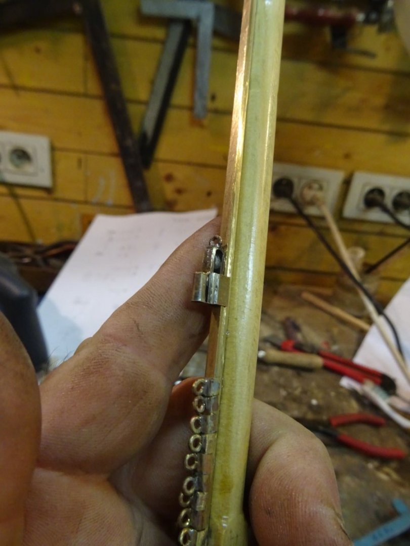
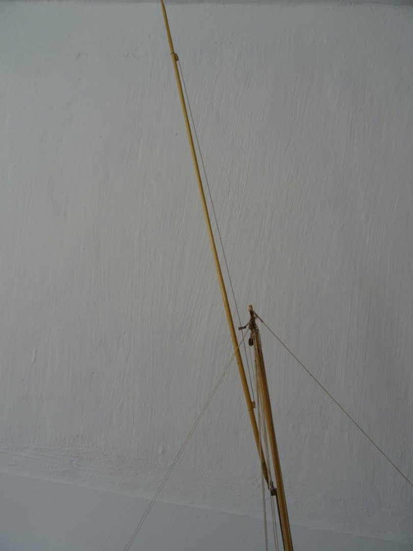
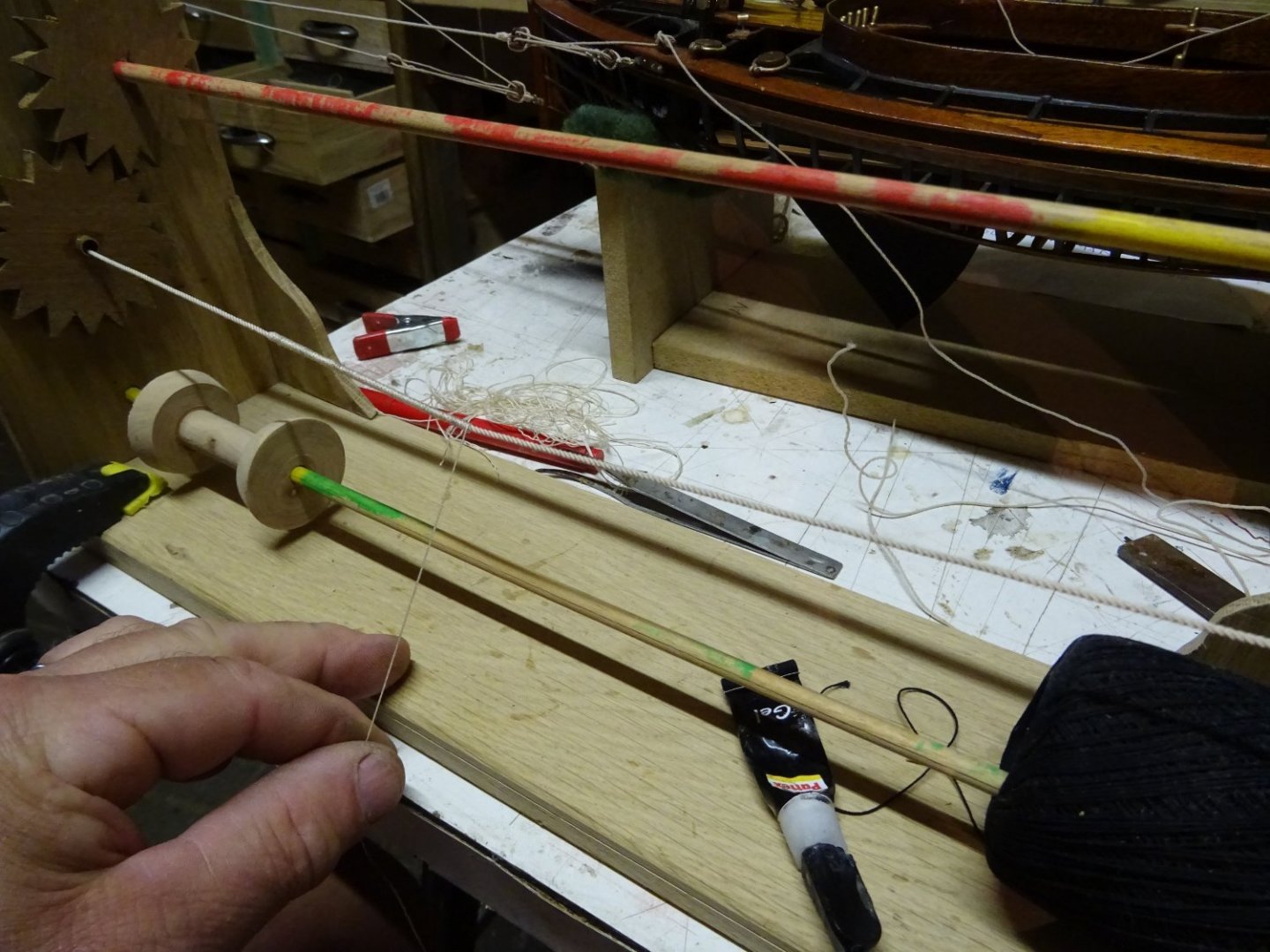
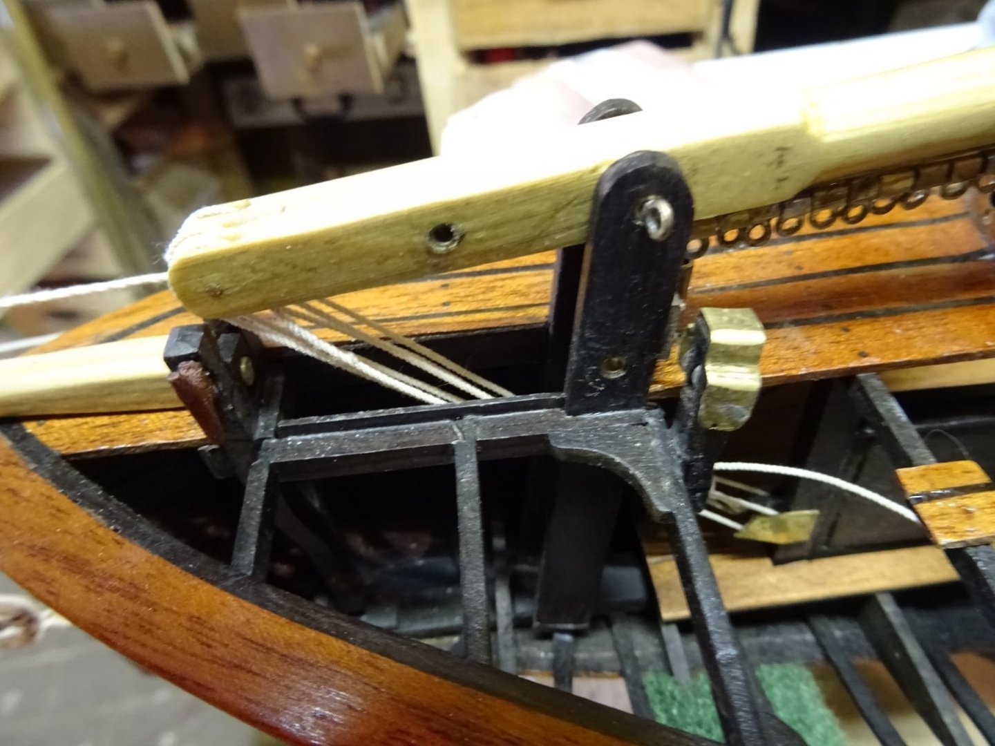
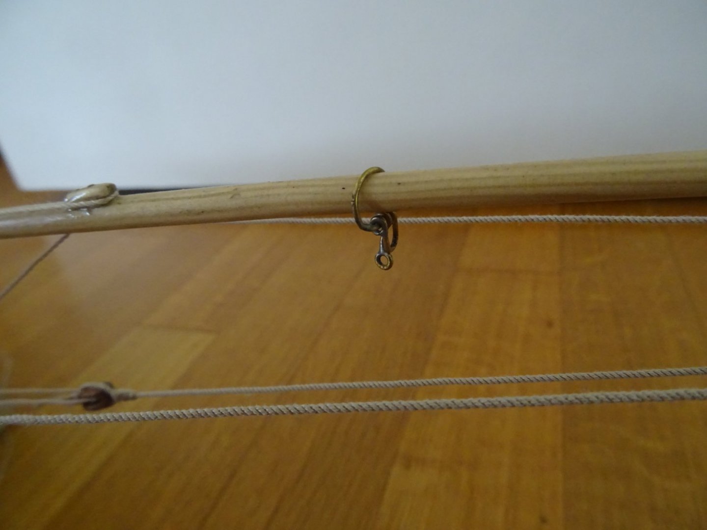
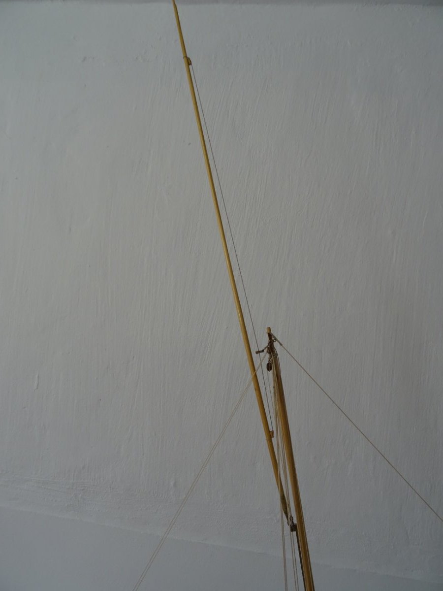
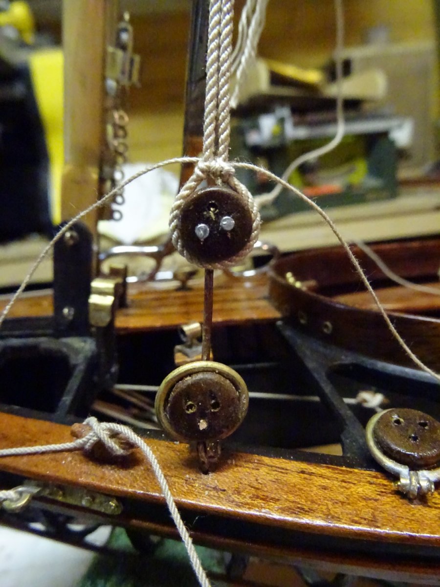
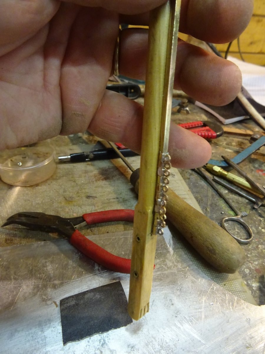
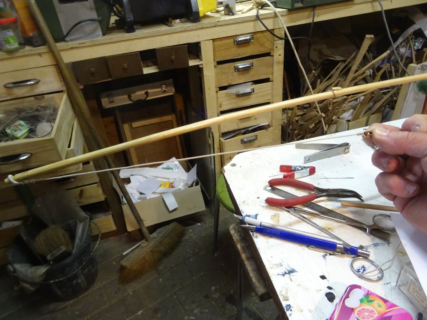
When the gunter is raised on the mast, it is held upright by a metal violin block that runs along a guide rope.
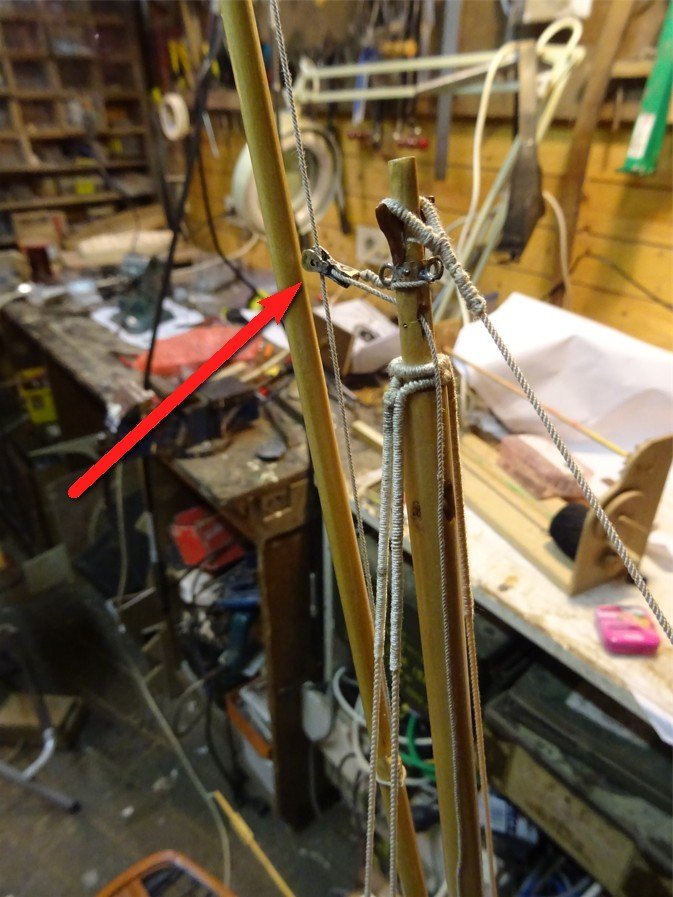
The hoisted gunter.
Thank you very much for reading this log and for your likes and for your constructive comments.
Till soon!
- B-Ram, Baker, Wintergreen and 12 others
-
 15
15
-
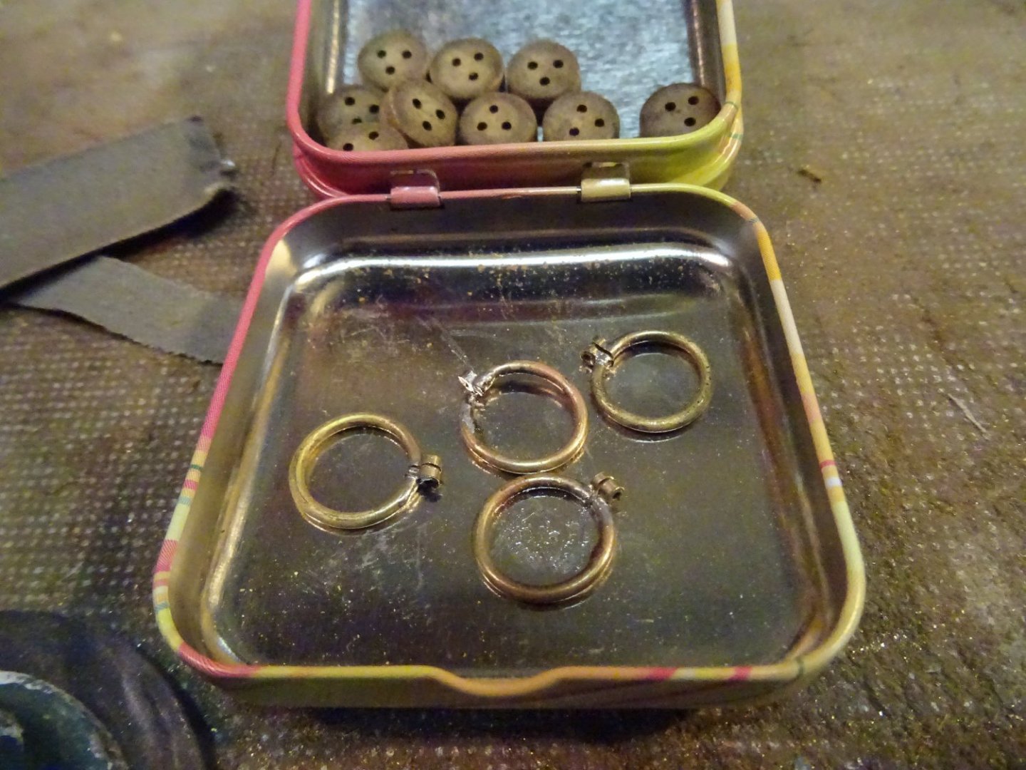
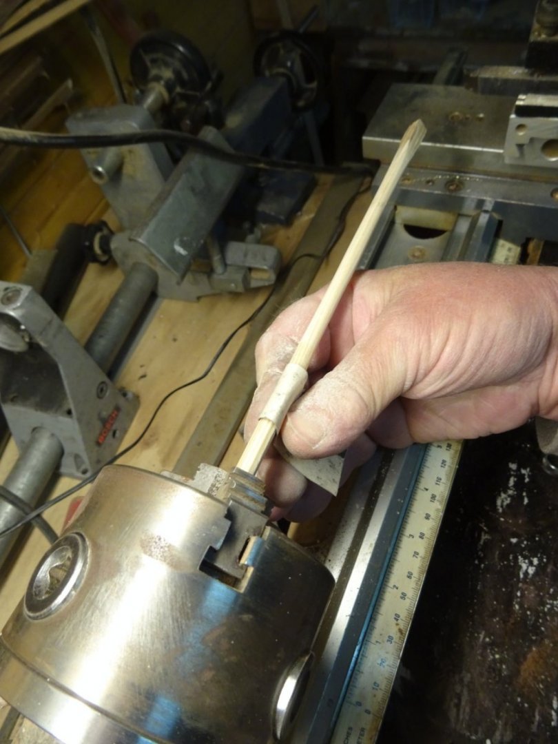
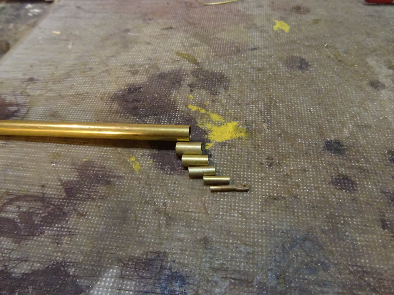
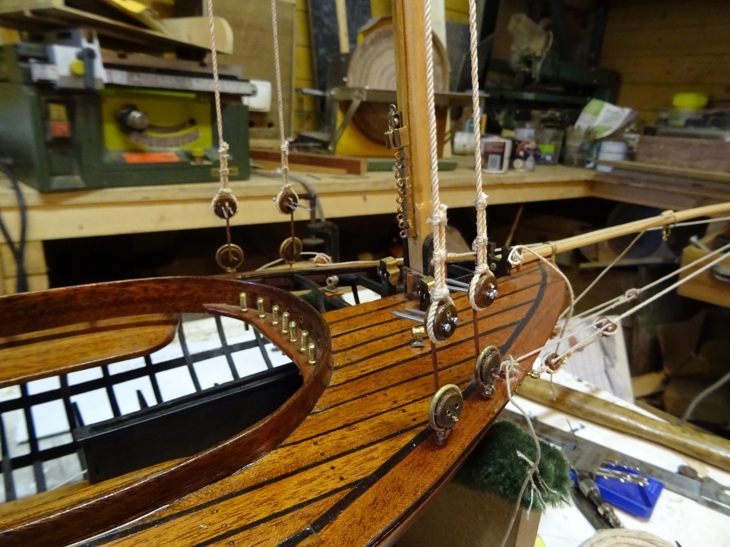
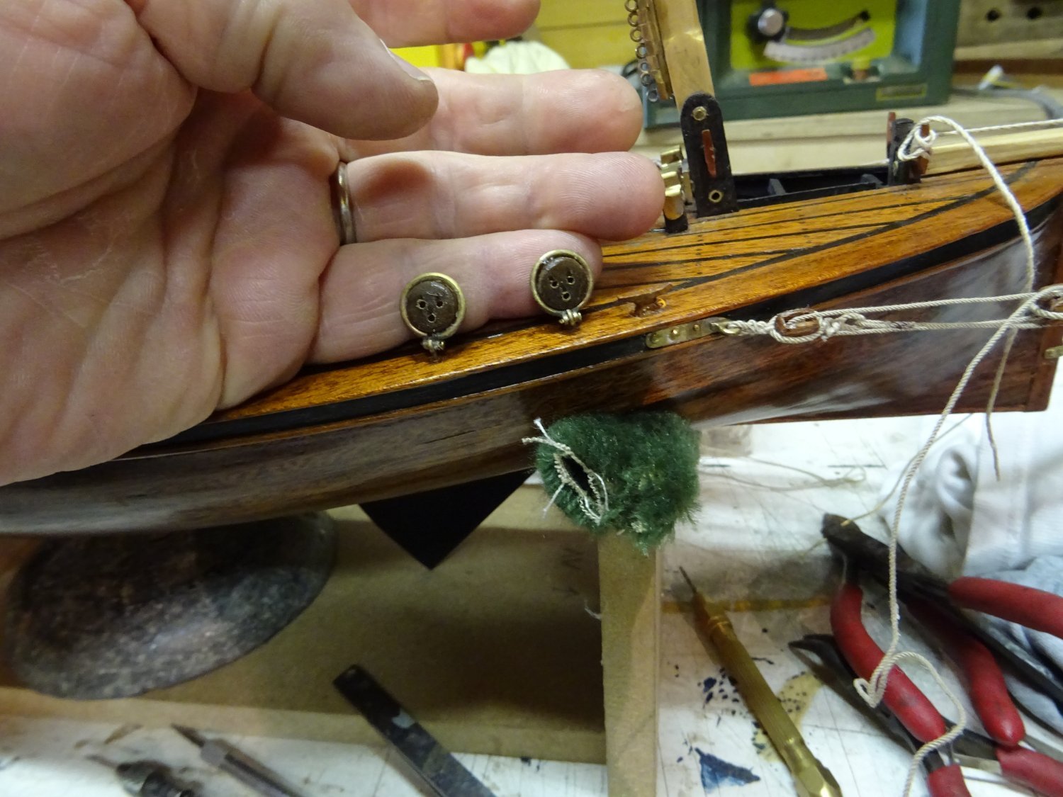
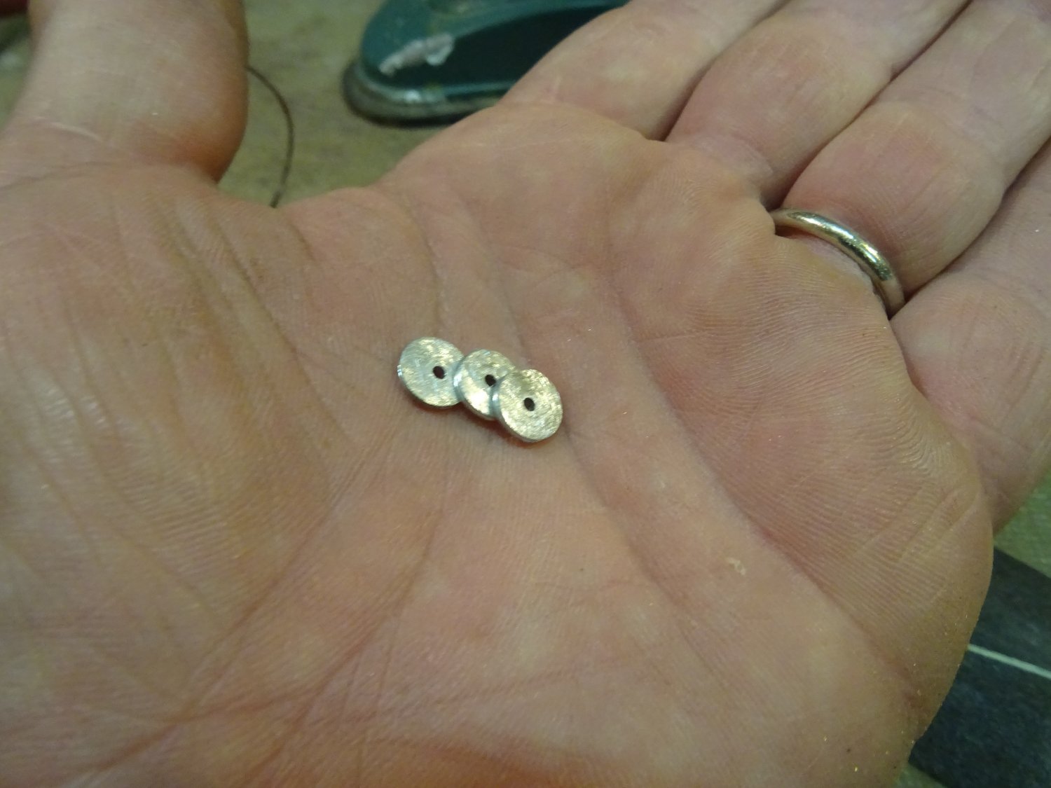
5. Pins
Before continuing on the spars I want to make the pins first. The pins are made of a brass rod over which a brass tube of half the length is soldered.
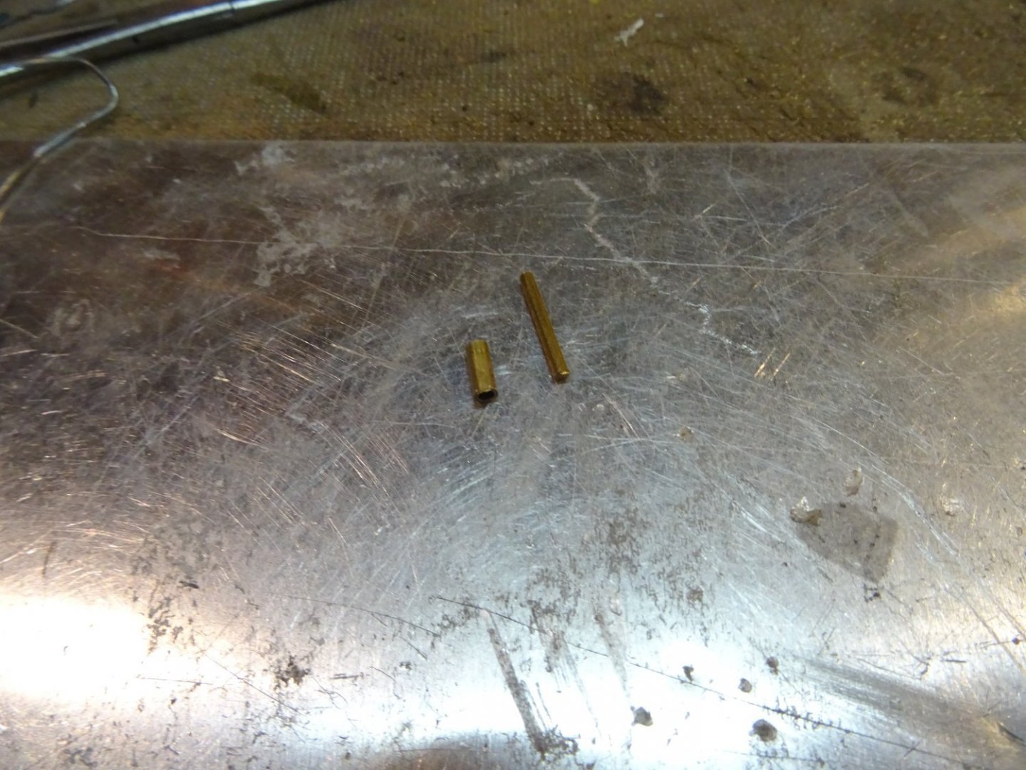

The tube becomes the handle and is filed into shape with different files (not only this big one).

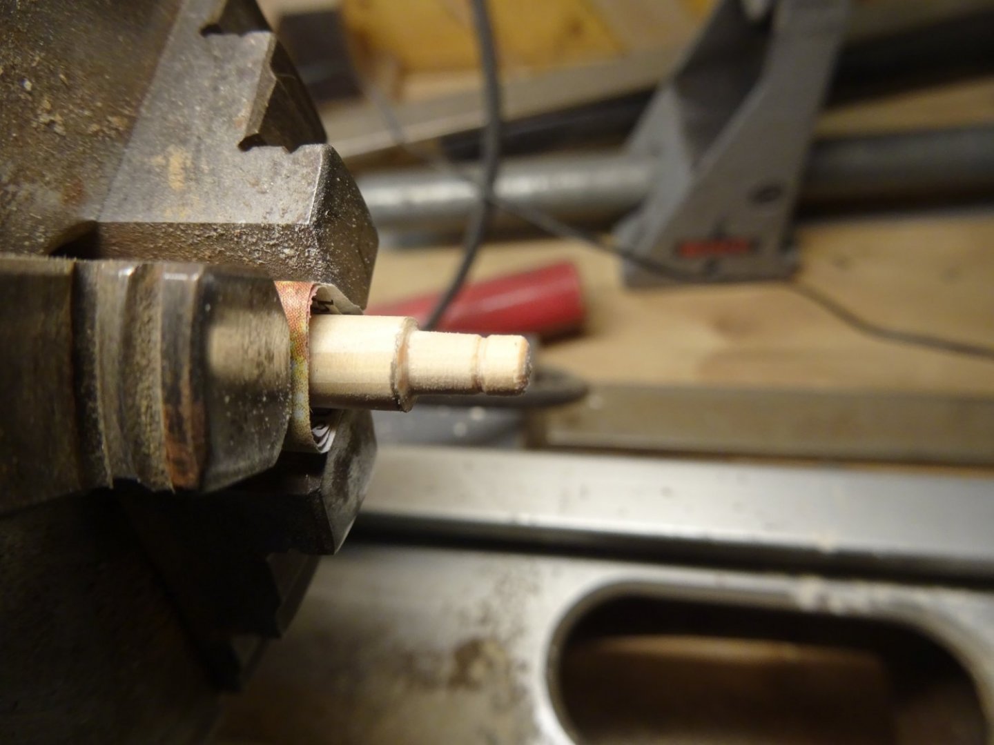
In this photo you can see the three successive steps from left to right.
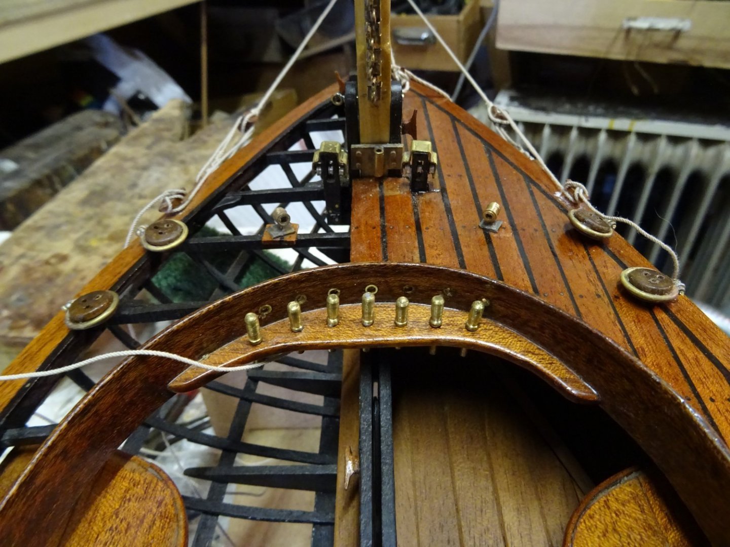
The pins in the pin rail.
- mtaylor, yvesvidal, Wintergreen and 6 others
-
9
-
-
On 3/6/2022 at 1:22 PM, wefalck said:
That's a clever drilling jig for the deadeyes 👍
I am actually quite surprised that such kind of boat still uses deadeyes. Given the quite close connection that the French yachtsmen had with those in the USA, I would have thought, that screws might have been used already. Or hearts and lanyards. Deadeyes look rather 'rustic' on such a boat.
Well I also think turnbuckles seem more normal for this type of boat than dead eyes. There are no dead eyes to be seen in the 19th century paintings of the Seine sailors either, but these are mostly impressionistic paintings in which no details can be seen. Frankly, I'm glad there are dead eyes on the plan because turnbuckles seem much harder to make to me.
- mtaylor and FriedClams
-
2
-
The part of the shrouds that goes around the masthead is served.

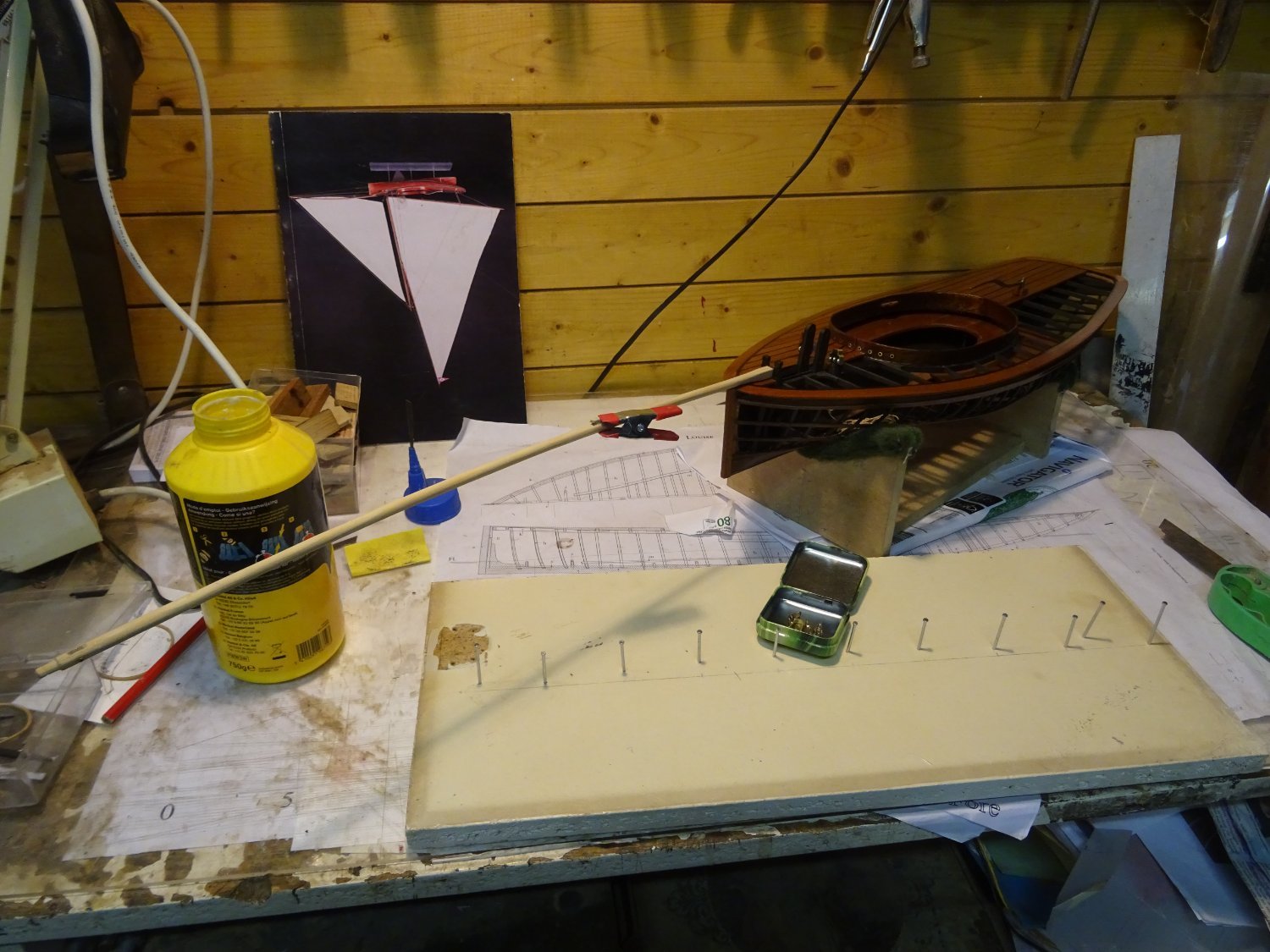
I make a small spacer gadget to help me to keep the space between the dead eyes equal. Two small nails in the top dead eye avoids it twisting.


Now the lanyards go through the dead eyes
and that is the situation as it is now.
Thank you very much for reading this log and for your likes and for your constructive comments.
Till soon!
-
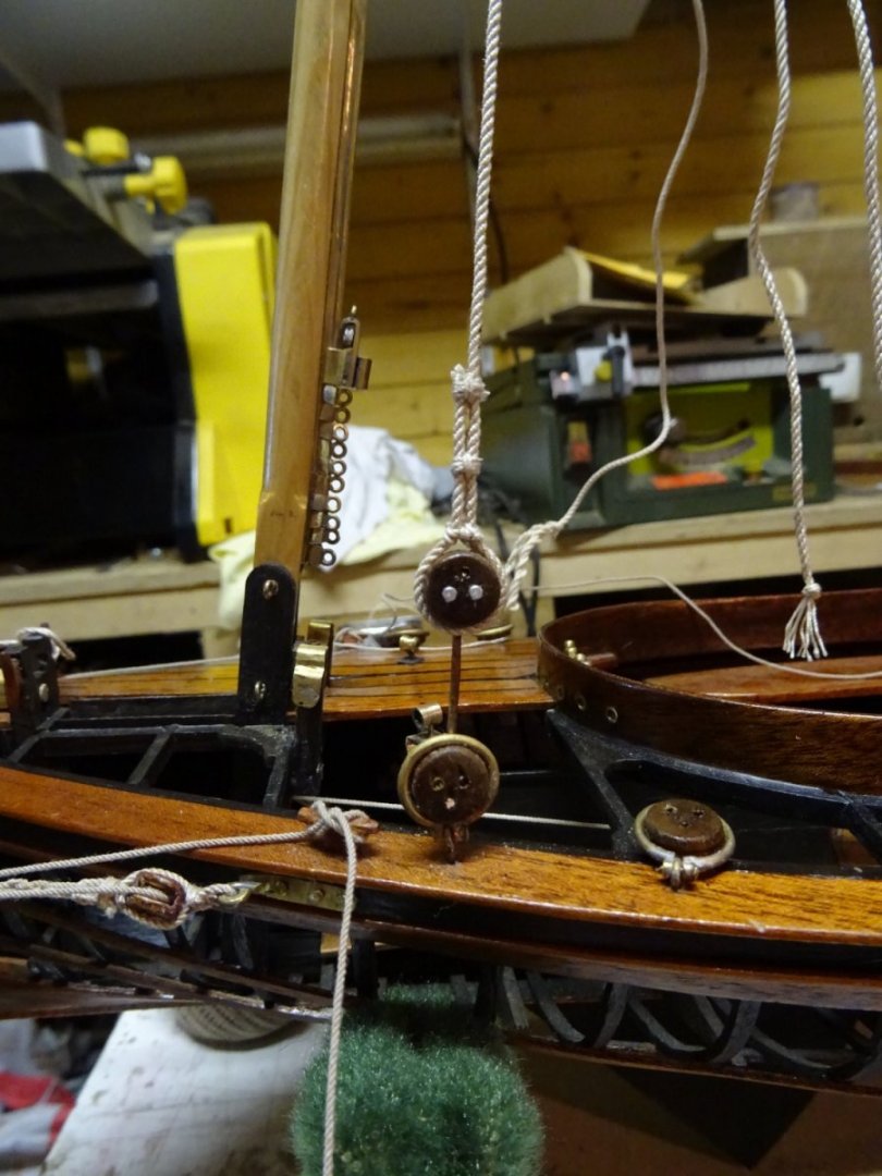
Time to rig the mast.
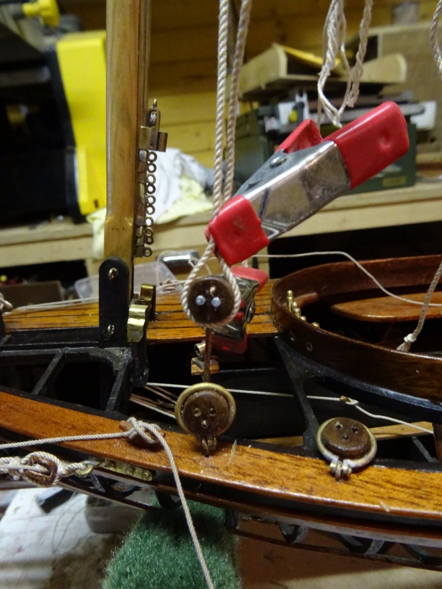
Before rigging the mast, the pulley of the tabernacle must be rigged. The halyard for erecting the mast has already been split at the fixed part of the hoist and must now be passed through the sheaves at the bottom of the mast.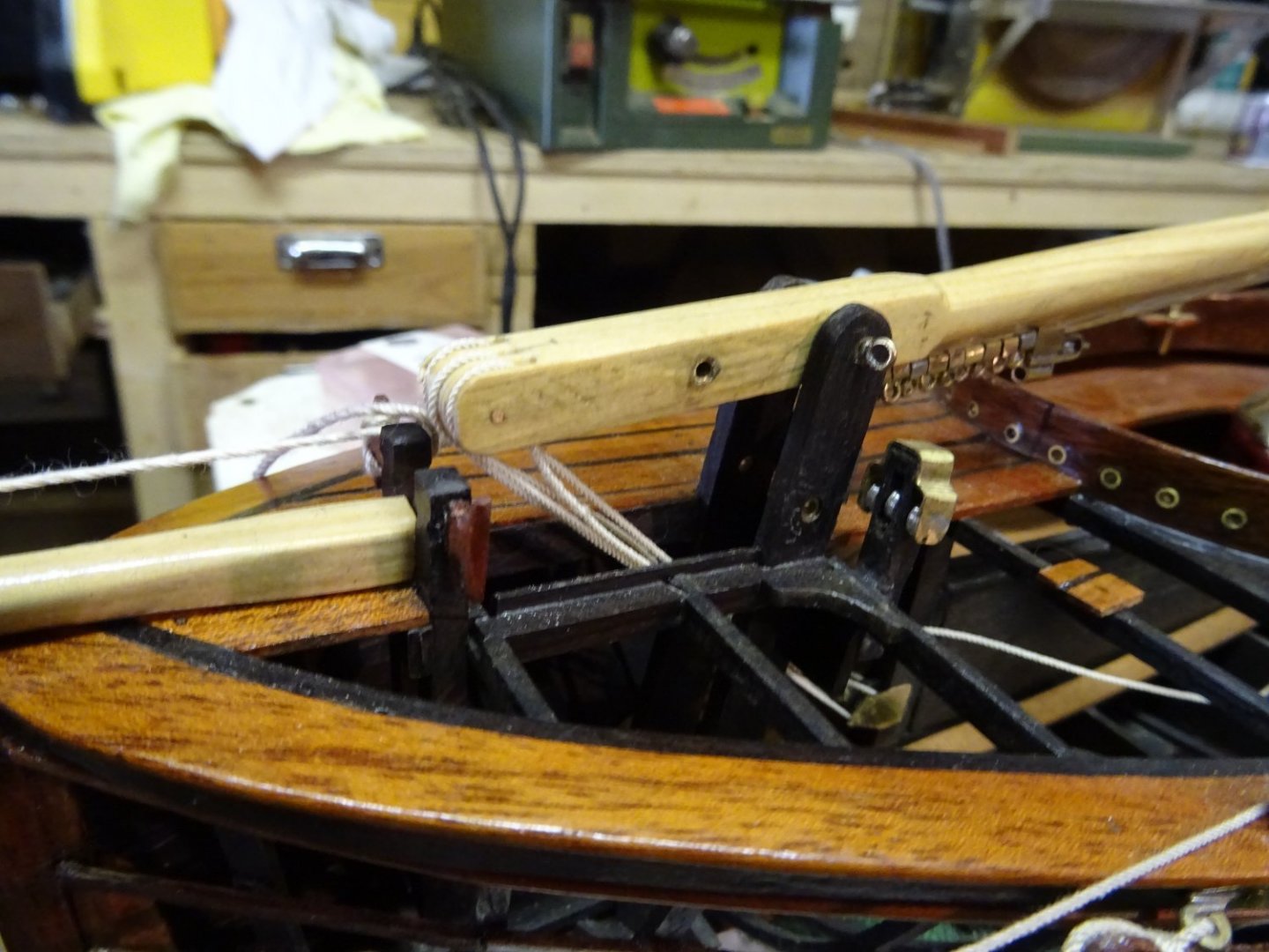
The mast is supported on both sides with two shrouds and dead eyes.
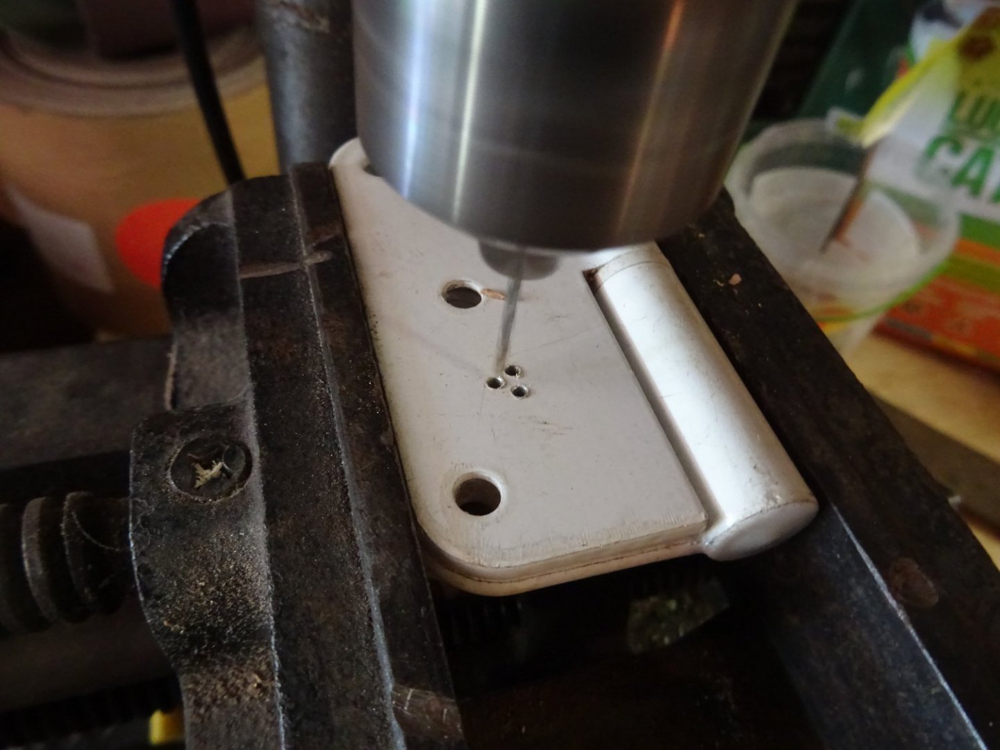
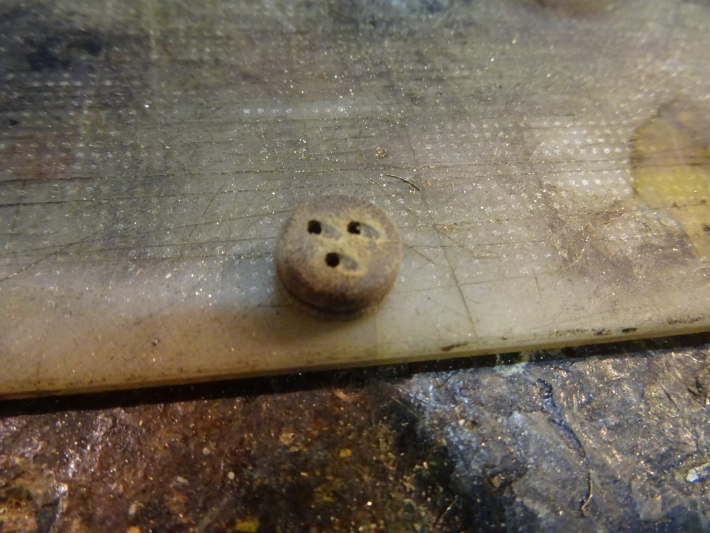
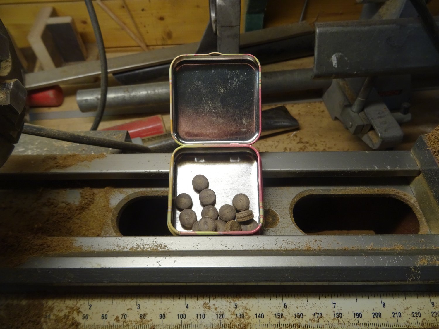
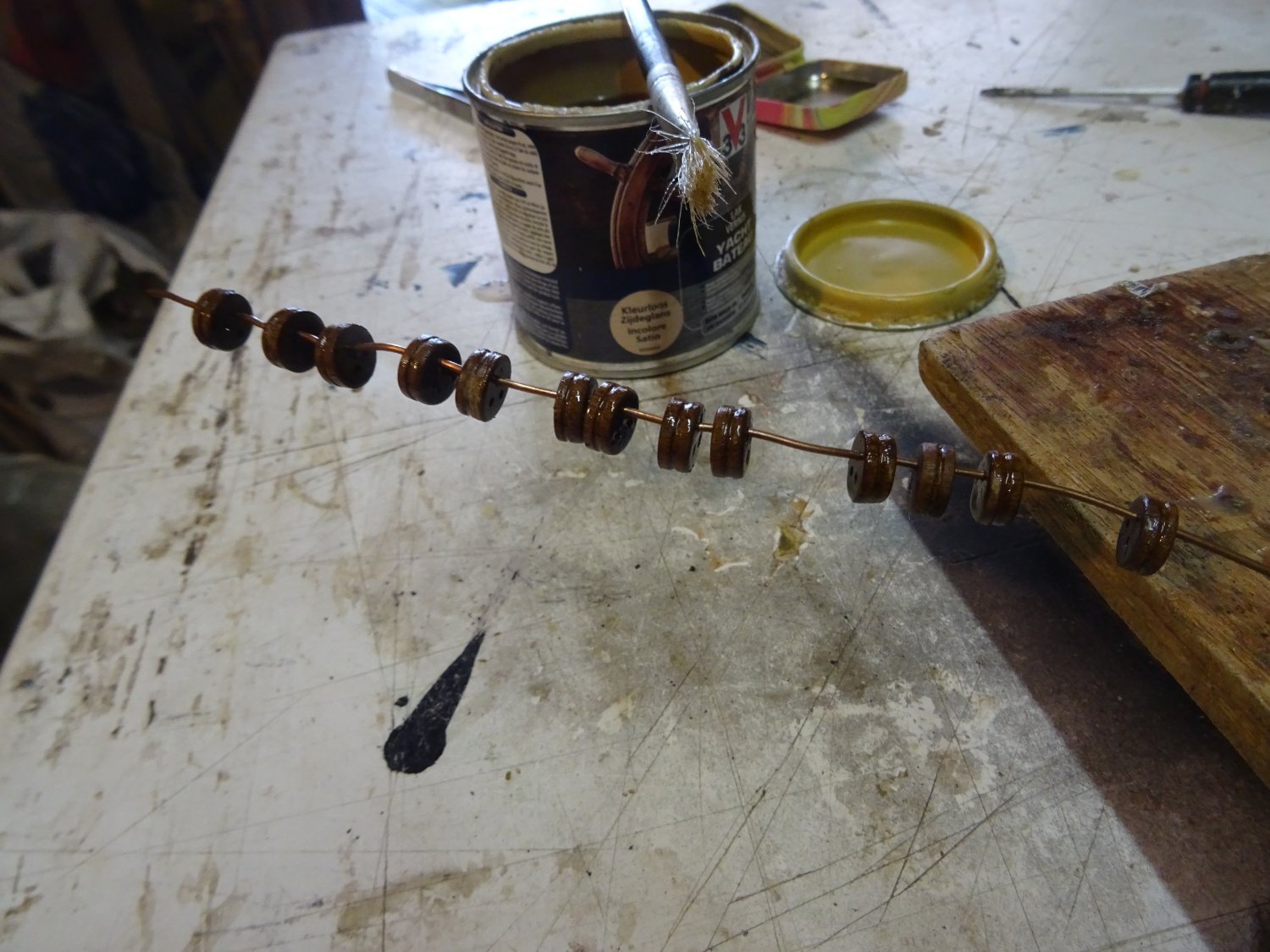
The dead eyes are tuned on the lathe from a piece of hard wood.


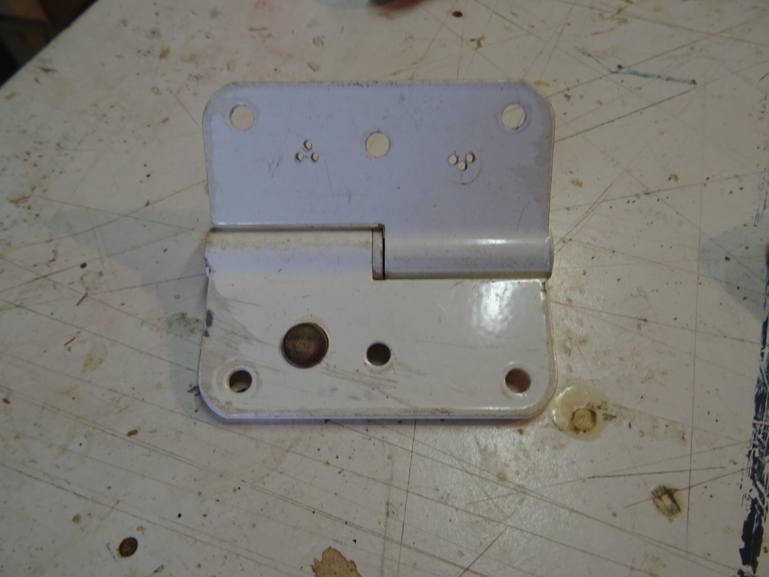
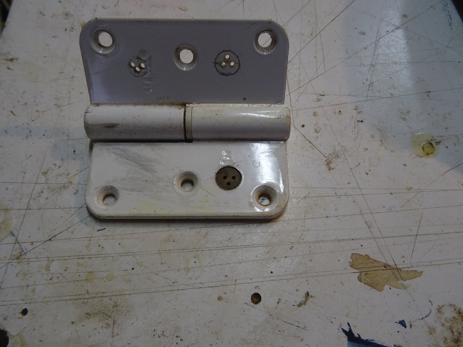
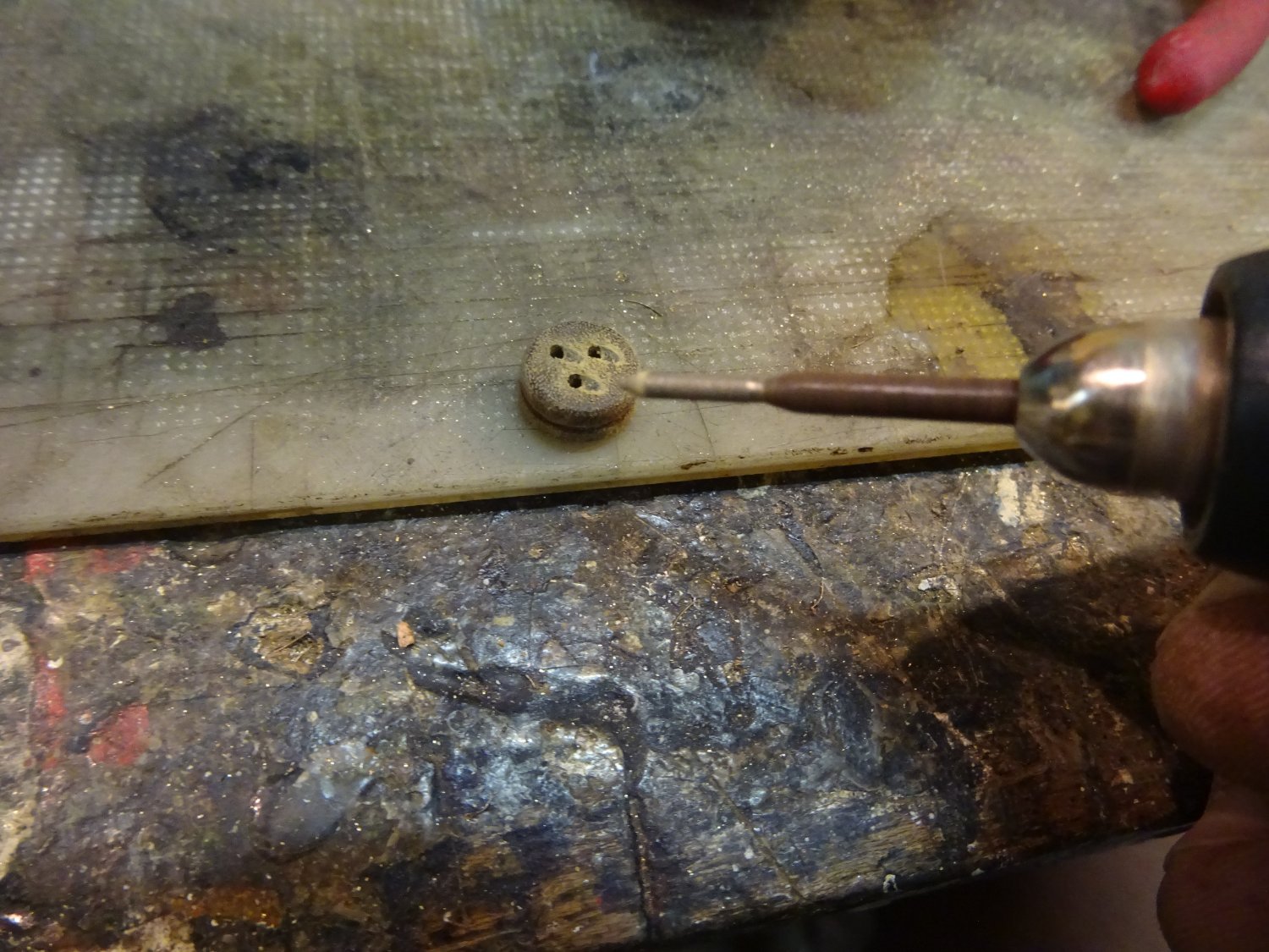
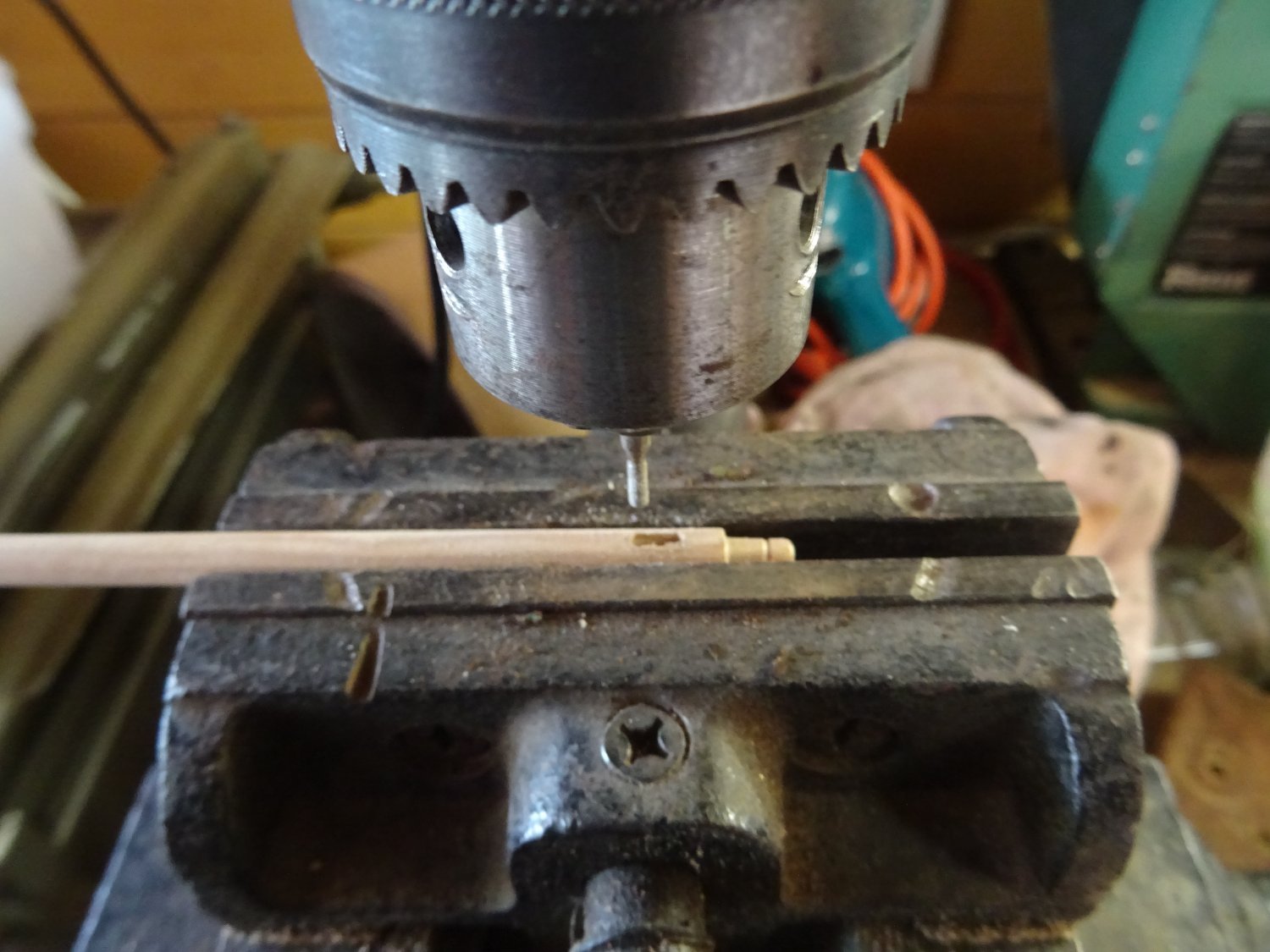
I use my proven hinge method to drill the holes in the right places.


Finishing:

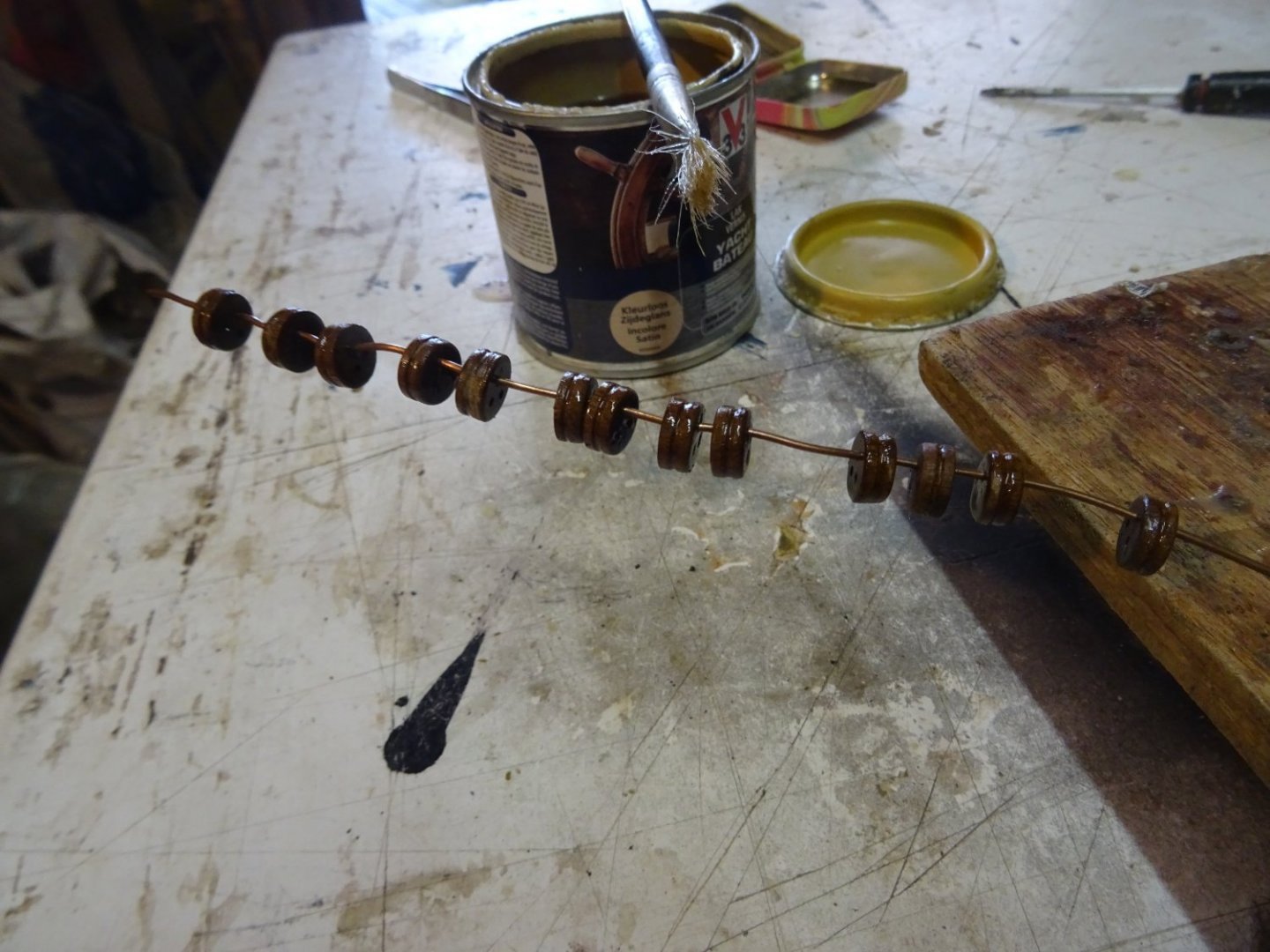
And varnishing
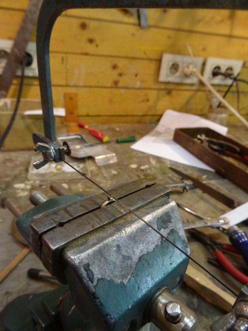
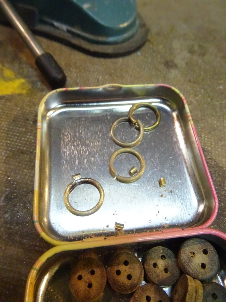
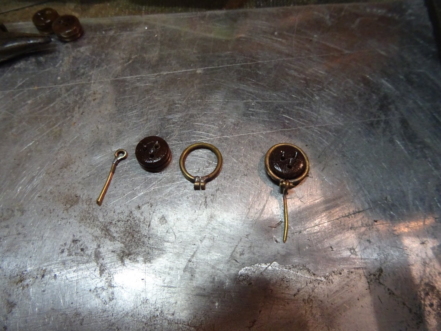
Making the strops


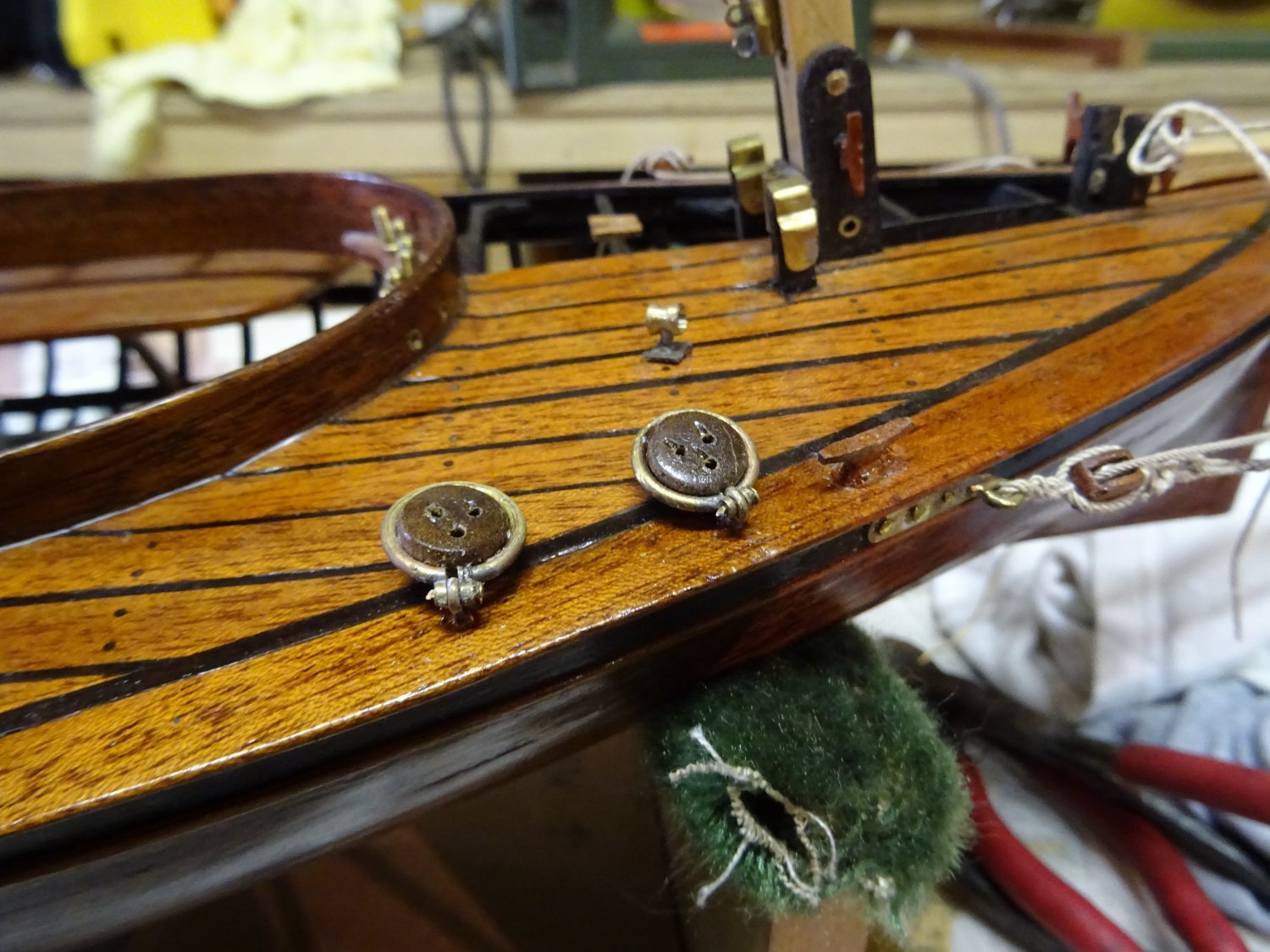
The dead eyes in place.


-
On 2/12/2022 at 6:35 PM, wefalck said:
Nice brass work!
I hope your rail stays put on the mast. I would be a bit worried about differential thermal expansion of the metal and the wood, and about knocking it off by accident. Perhaps glueing it into a slot in the mast would have been more secure?
Ebenhard,
You're probably right, but I don't have a precision milling machine to make a neat slot so I'm just trusting that the rail will only stay on the mast with glue.
On 2/12/2022 at 8:52 PM, jlefever said:Nice metal work indeed! Jim
Thanks Jim.
-
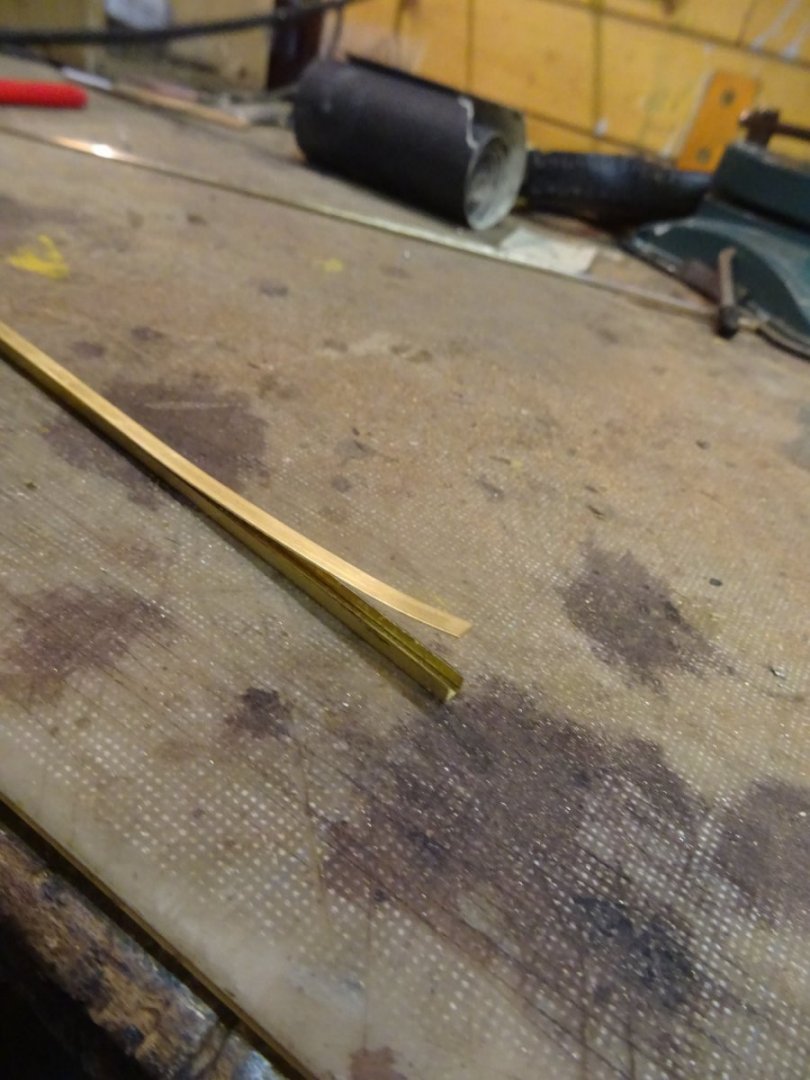
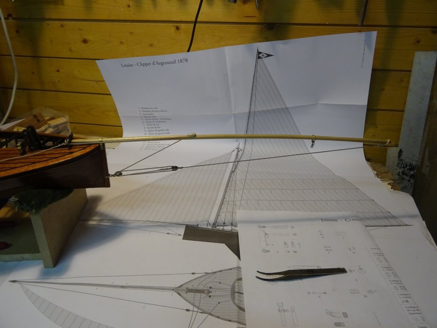
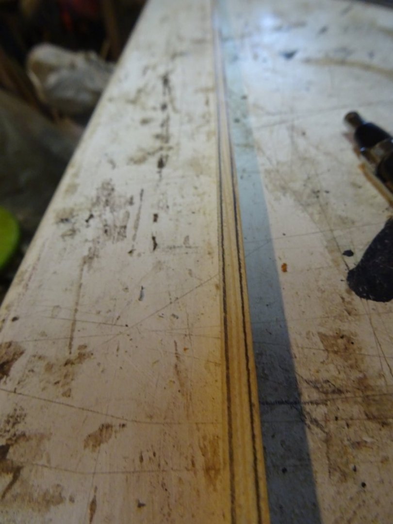
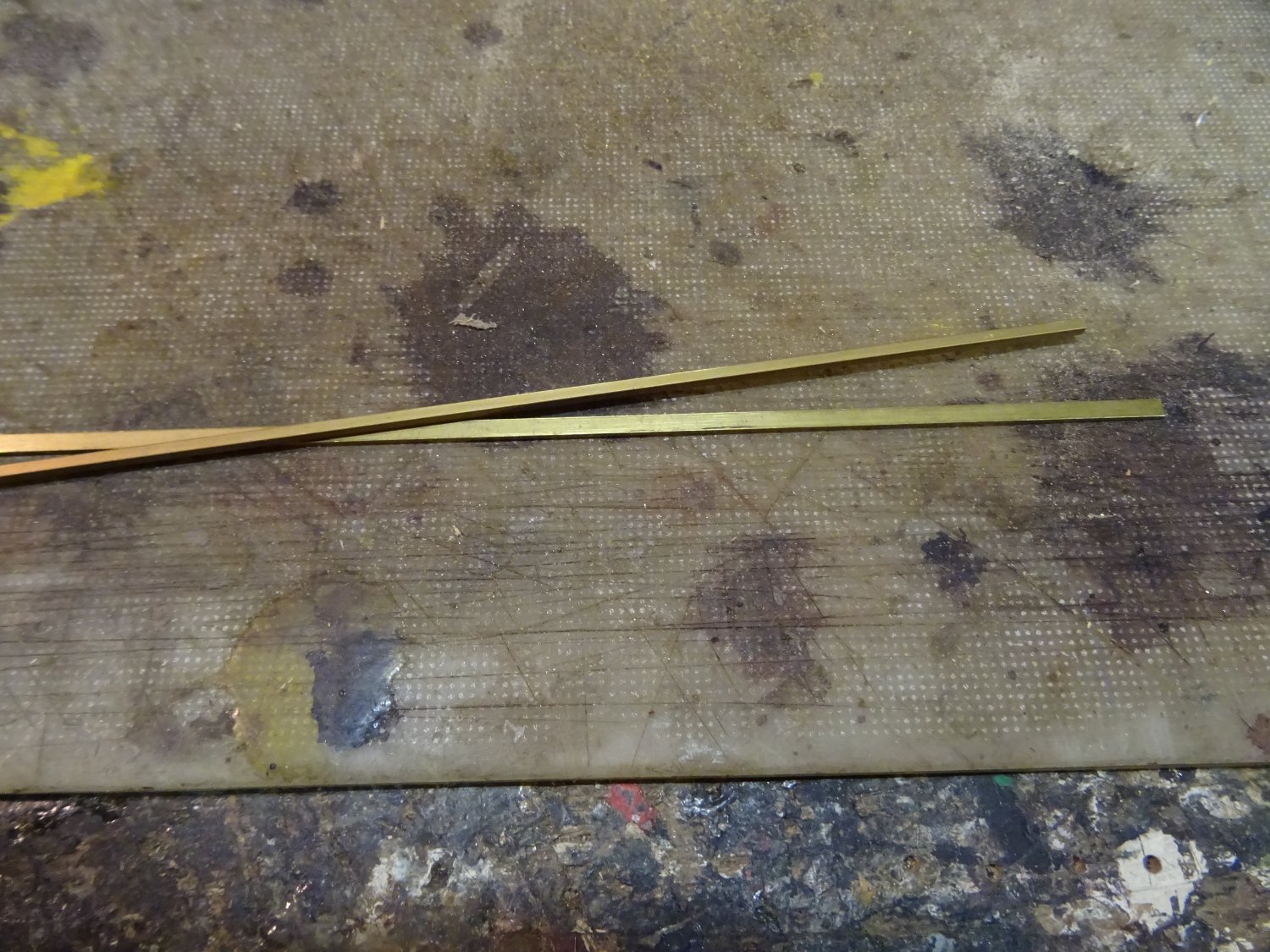
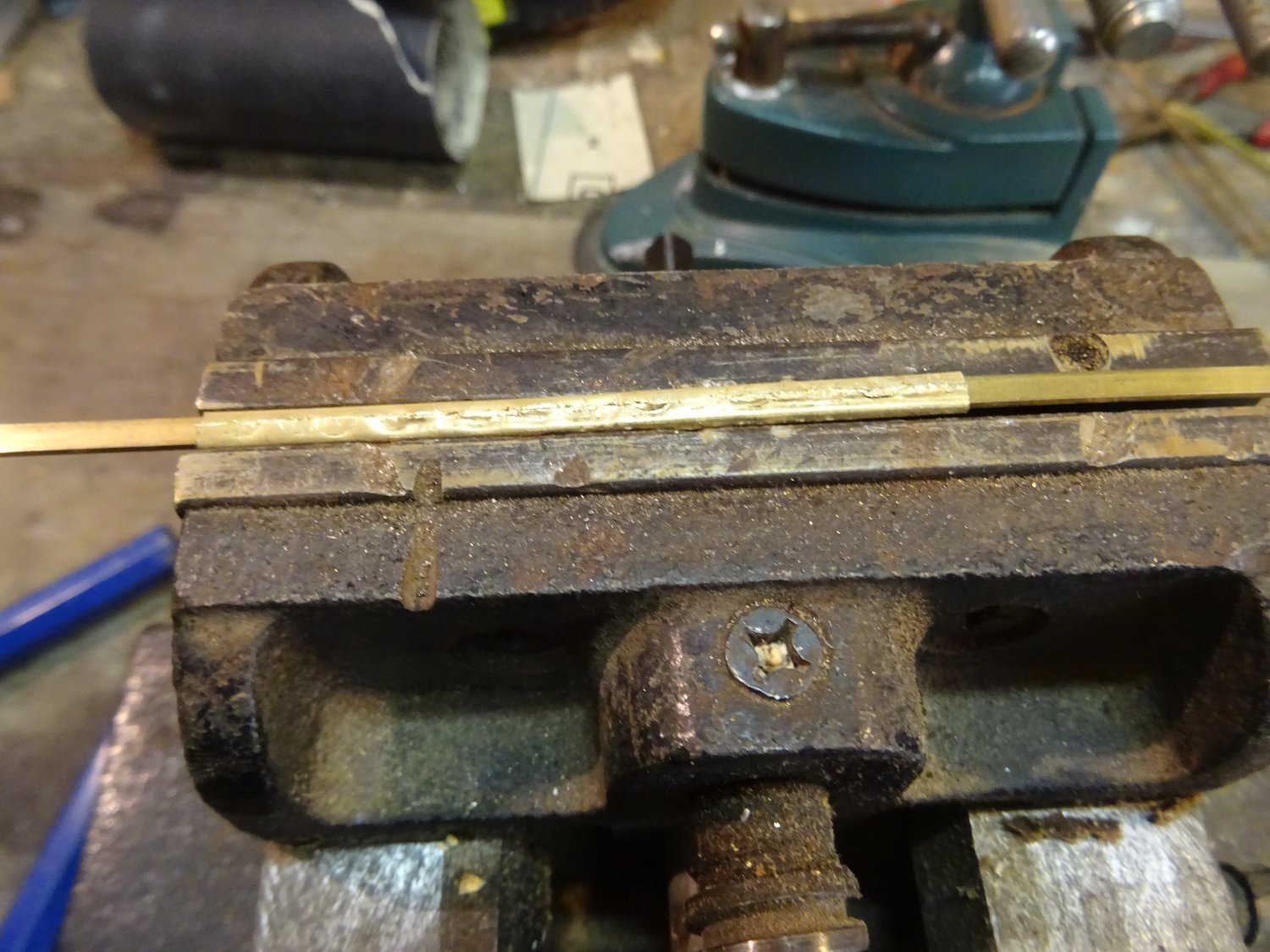
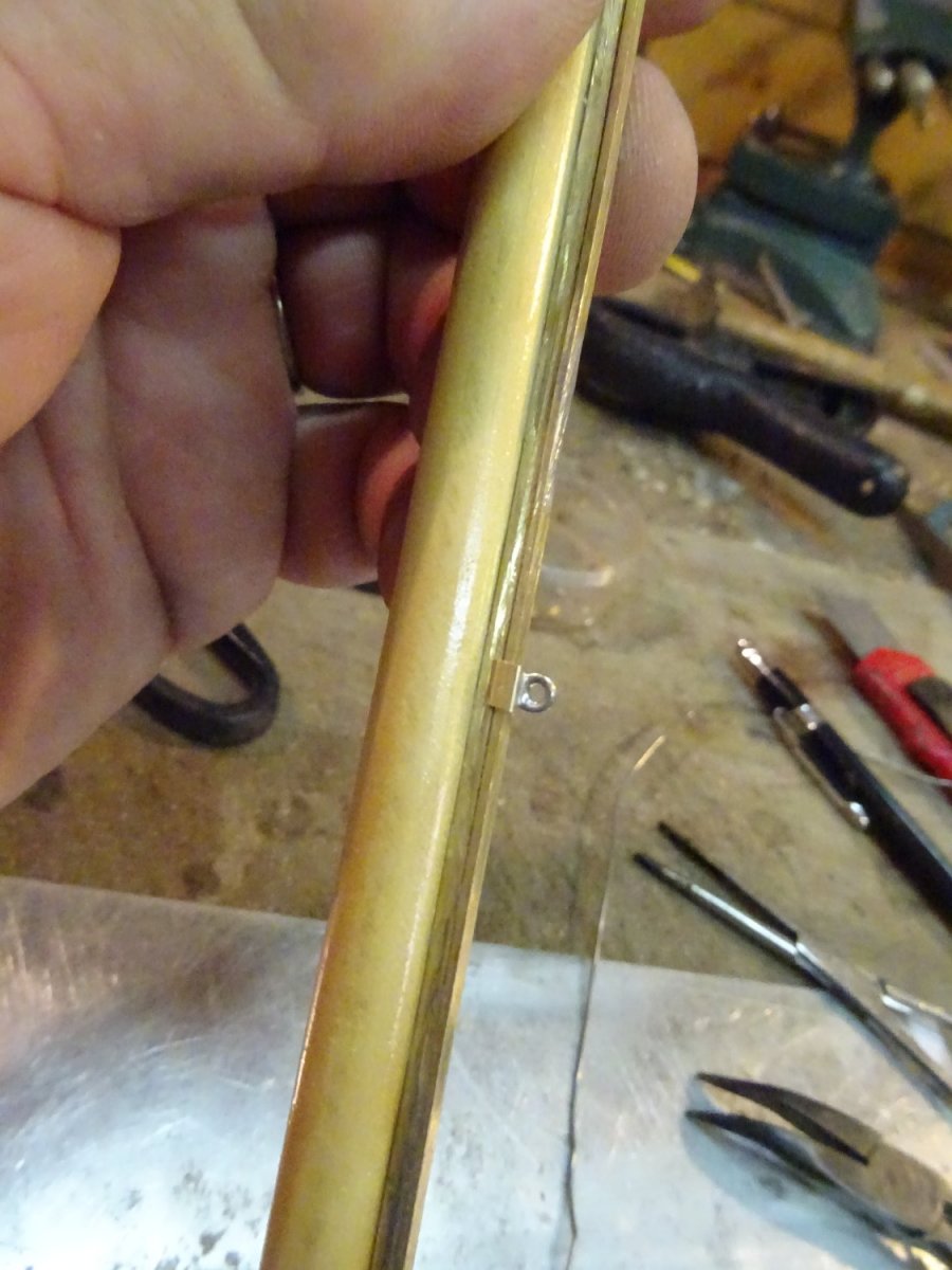
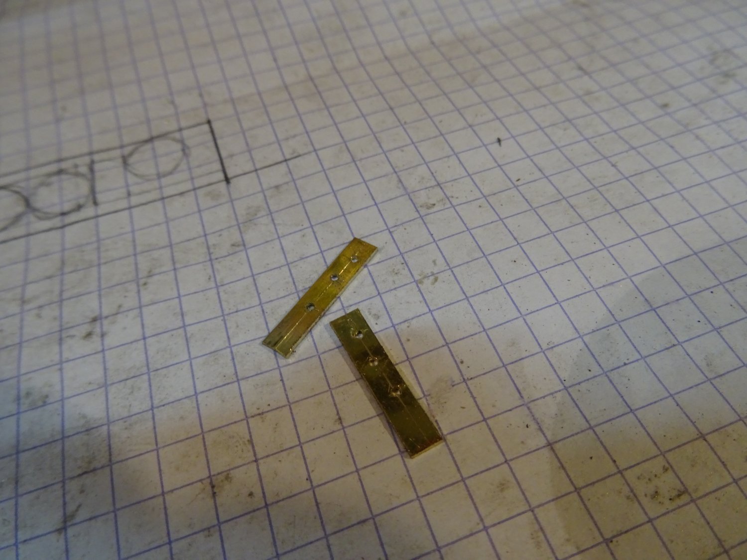
The mainsail is attached to the mast with slugs that run over a rail. To make the rail I solder two brass strips together. One with a flat profile on top and one with a square profile. It's hard to see in the picture but the drawing next to it shows what I mean.

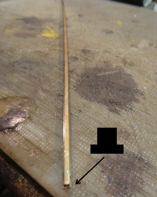
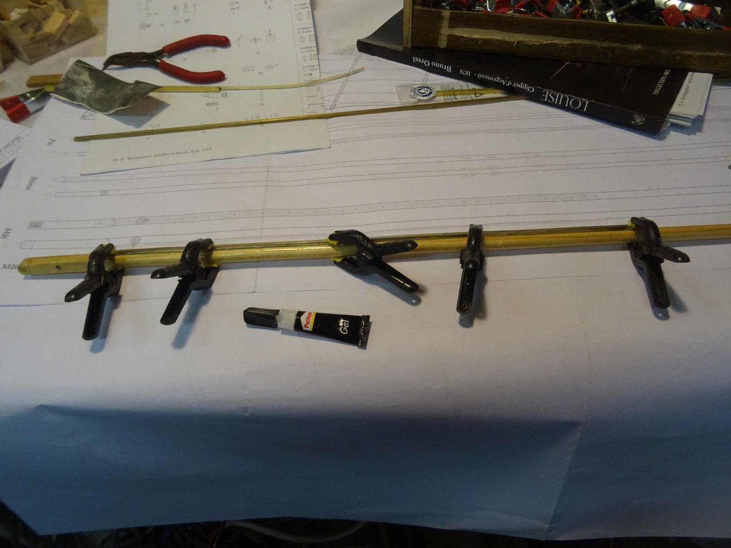
The rail is then glued to the mast.

Making the slugs is another matter. For some of you that is a piece of cake, but first I had to think about the method to follow. Finally I solved it like this: I saw off one side of a brass square tube with the same internal dimension as the rail.
Then I knocked the raised edges of the tube flat around a strip like the rail.

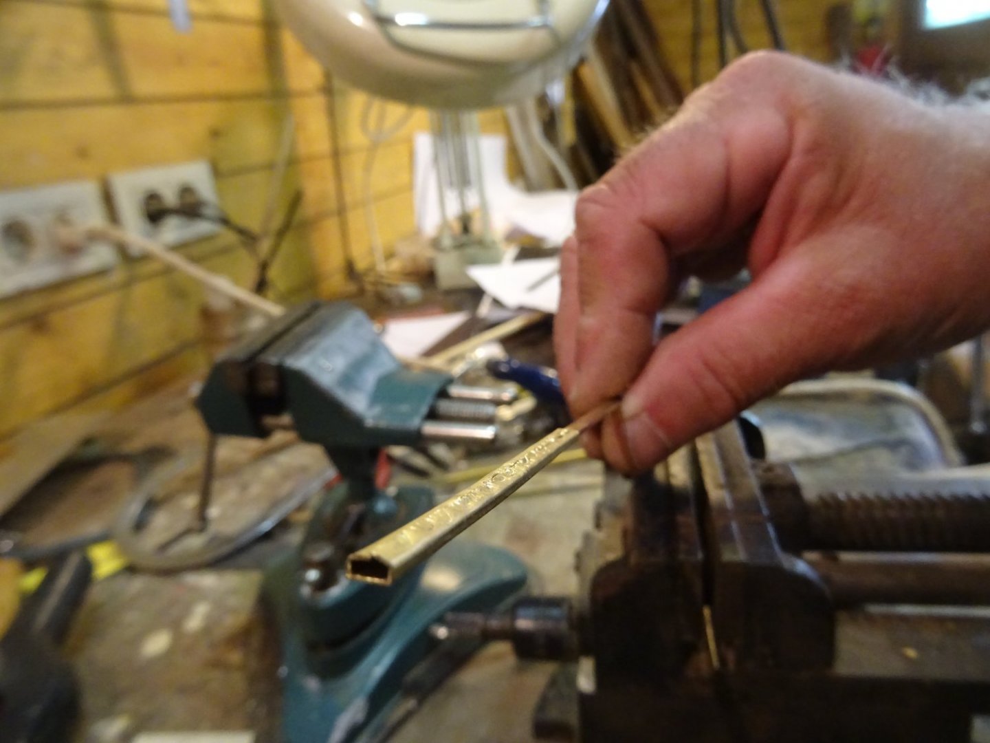
Next I saw a slit in the slammed side.
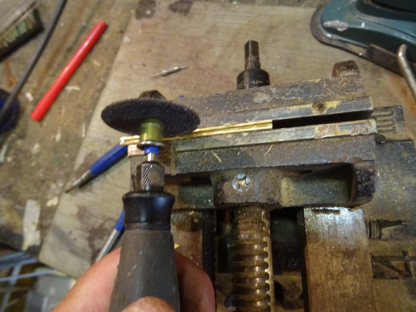
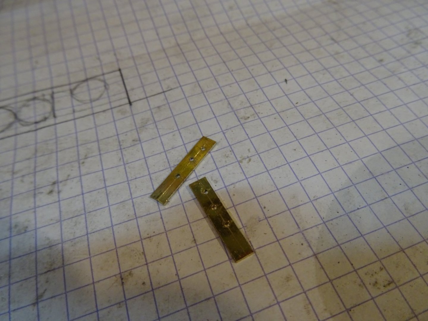
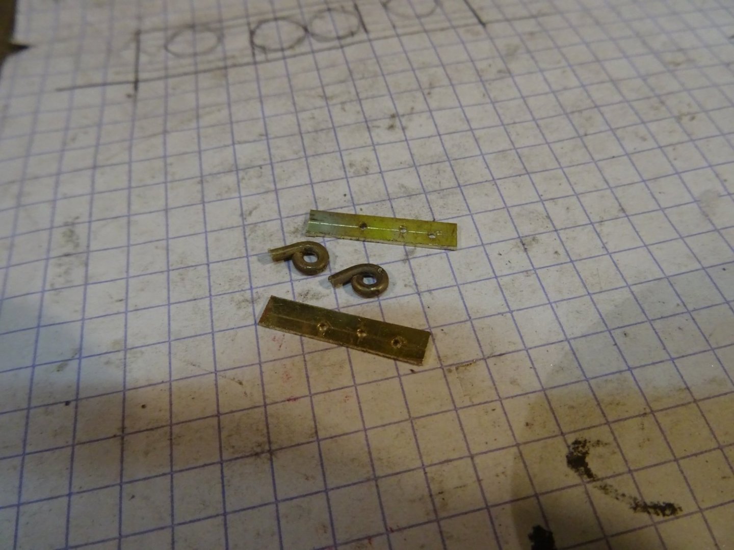
I saw my slug profile into pieces and also make small brass rings.
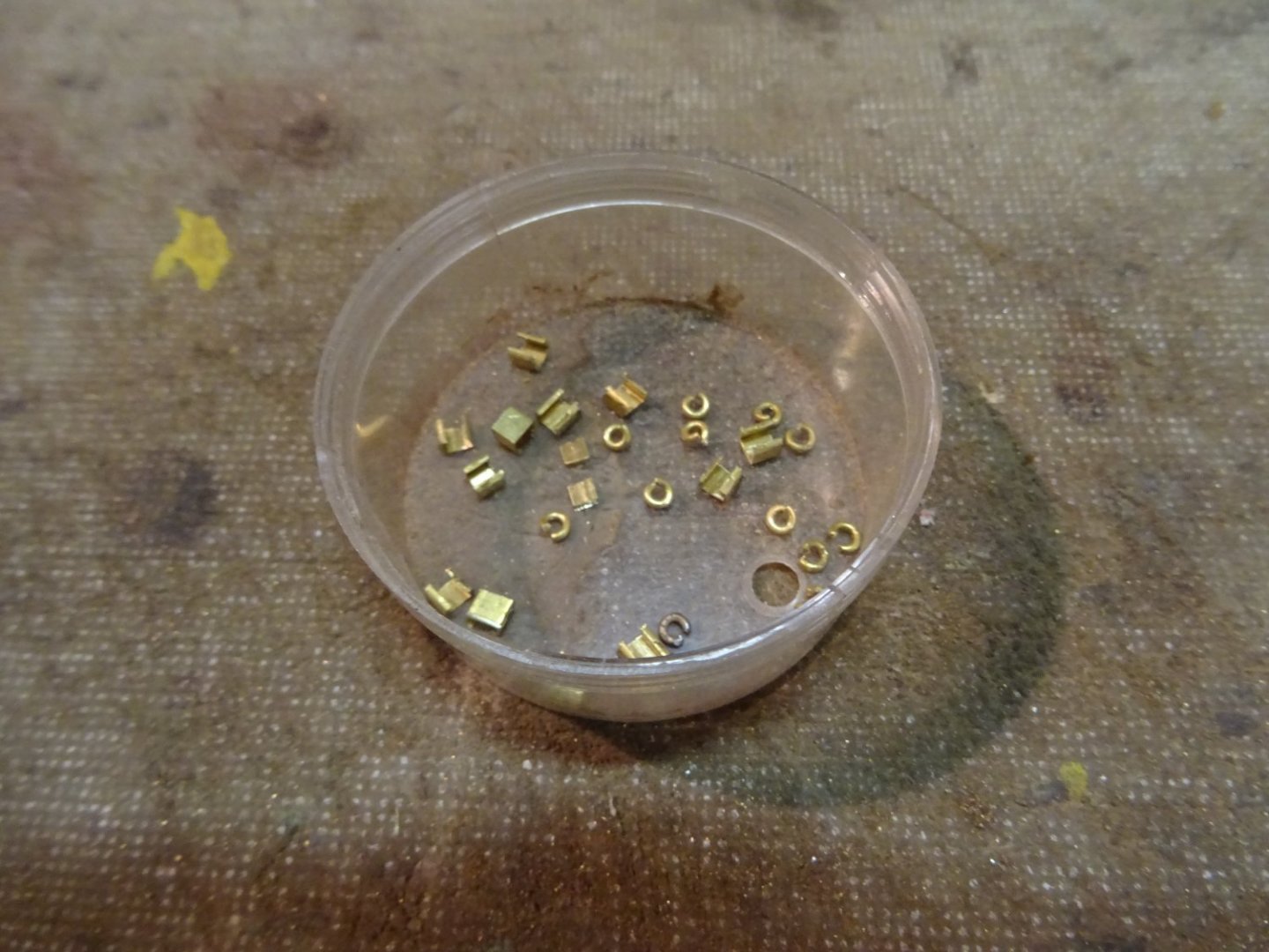
When I solder both together, I have a slug.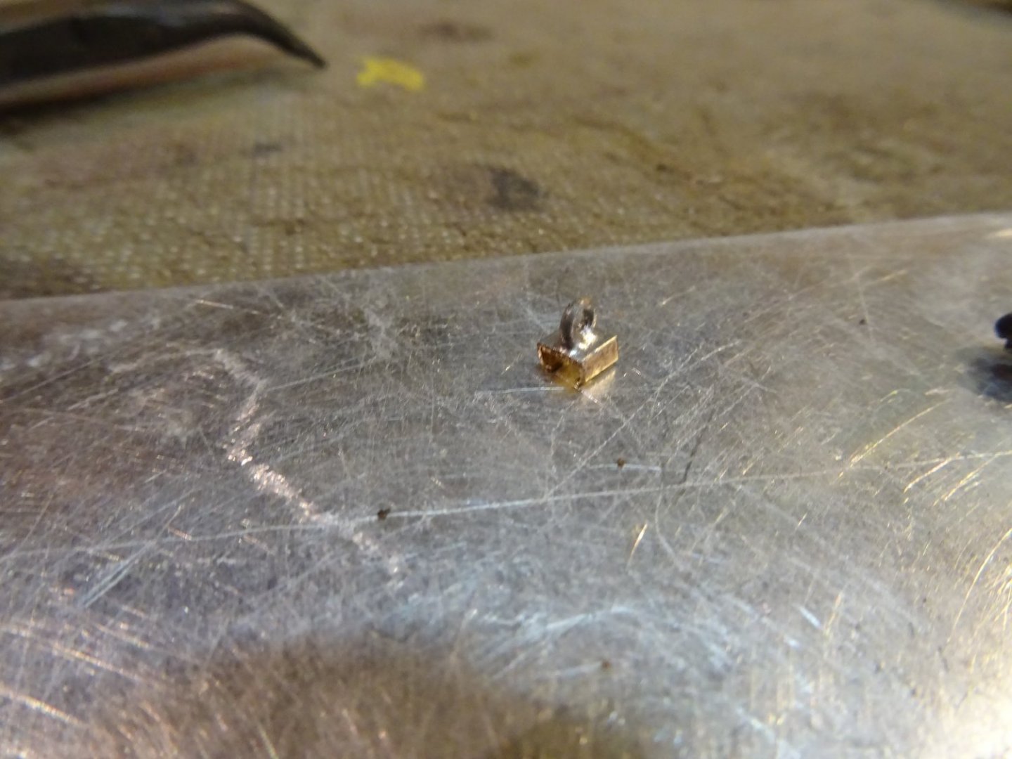
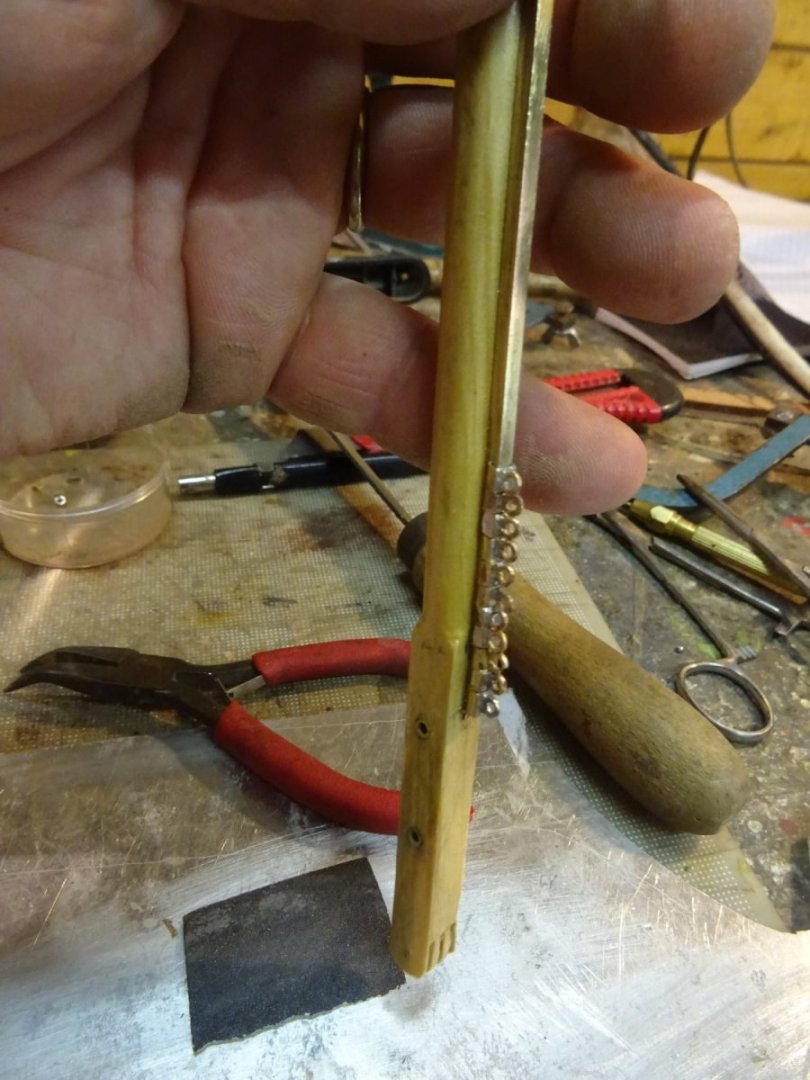
A slug on the rail.

All slugs on the rail.
Thank you very much for reading this log and for your likes and for your constructive comments.
Till soon!
- vaddoc, BobG, GrandpaPhil and 11 others
-
14
-
-
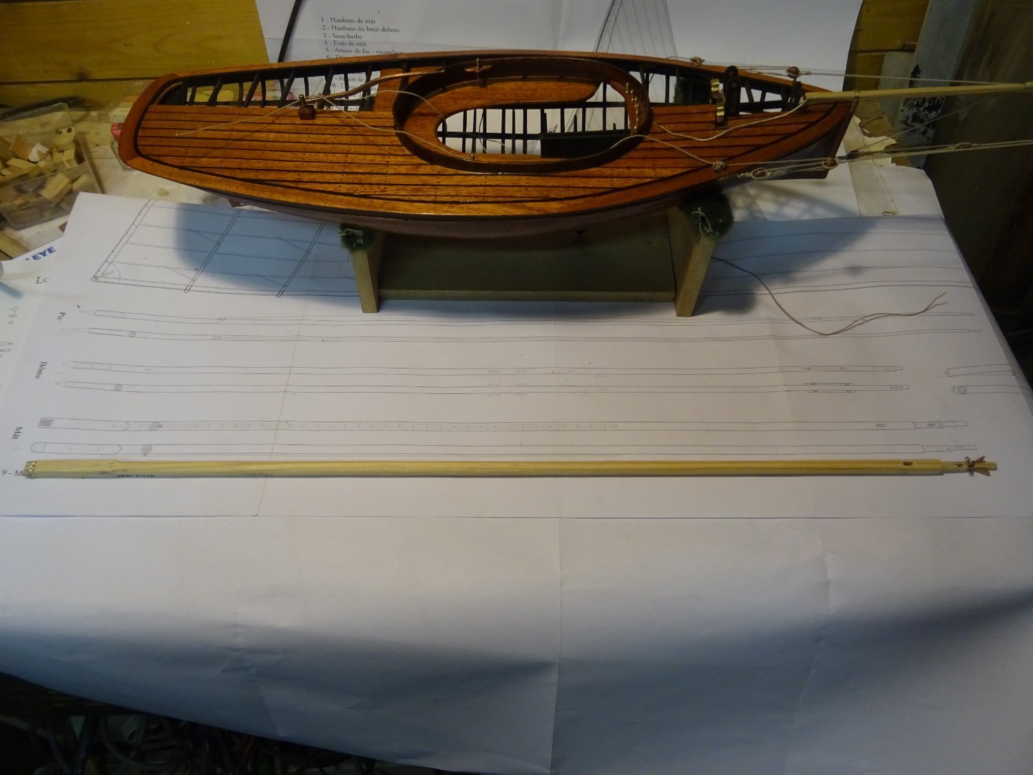
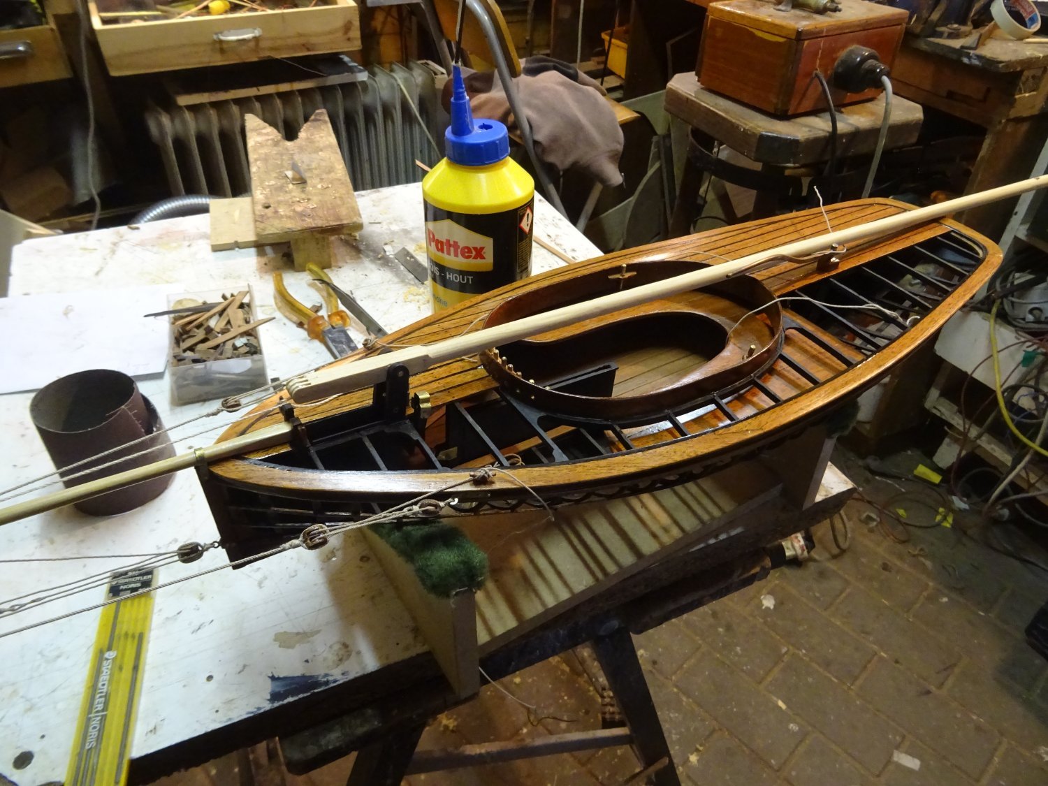
4. Mast
To make the mast, I first saw a square stick to the appropriate length. Here it stands in the tabernacle:

At the bottom of the mast step there are three slots in which the sheaves for the mast raising pulley come.
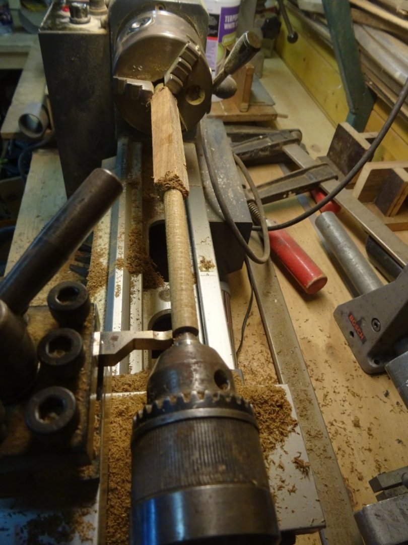
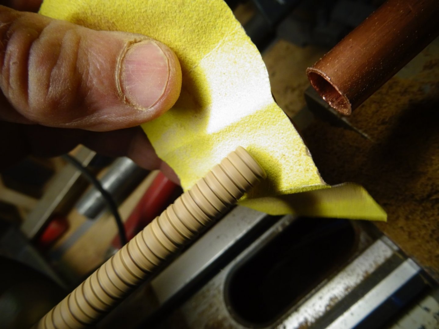
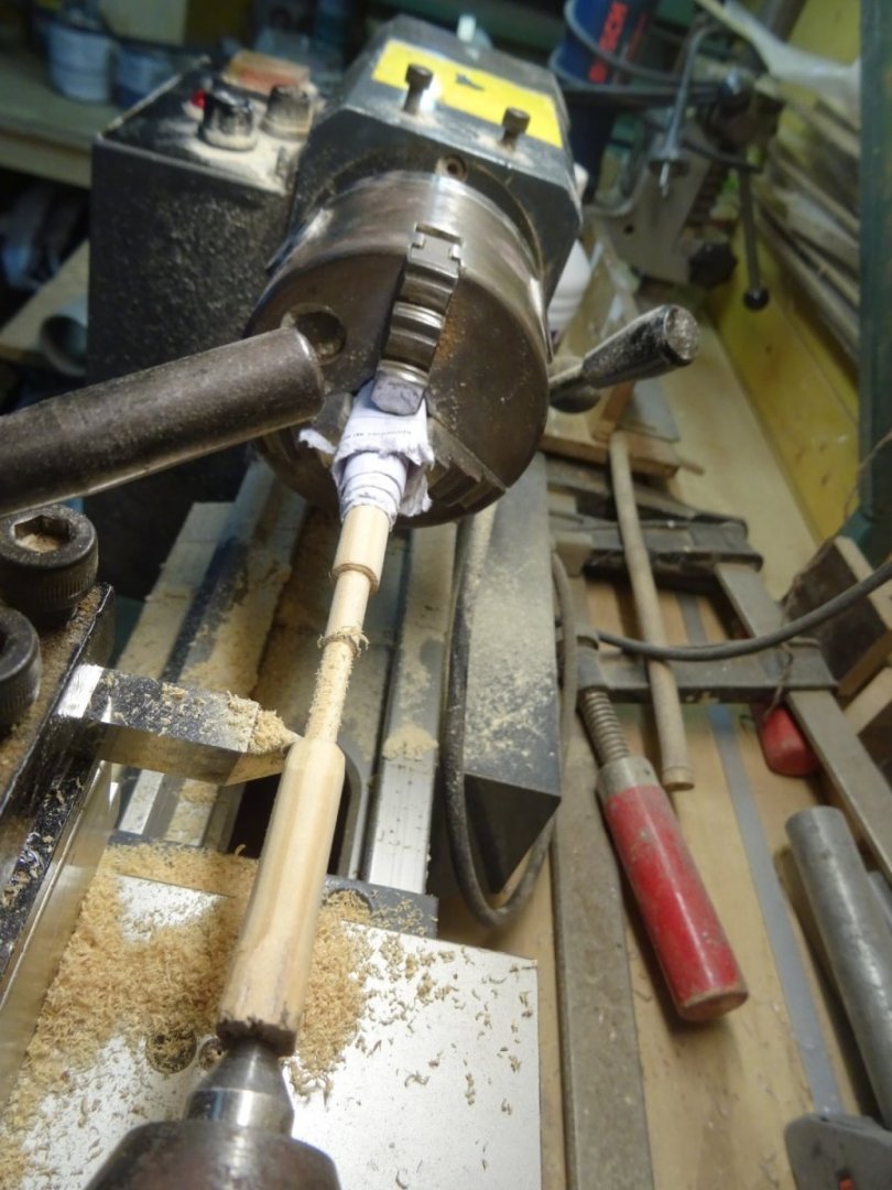
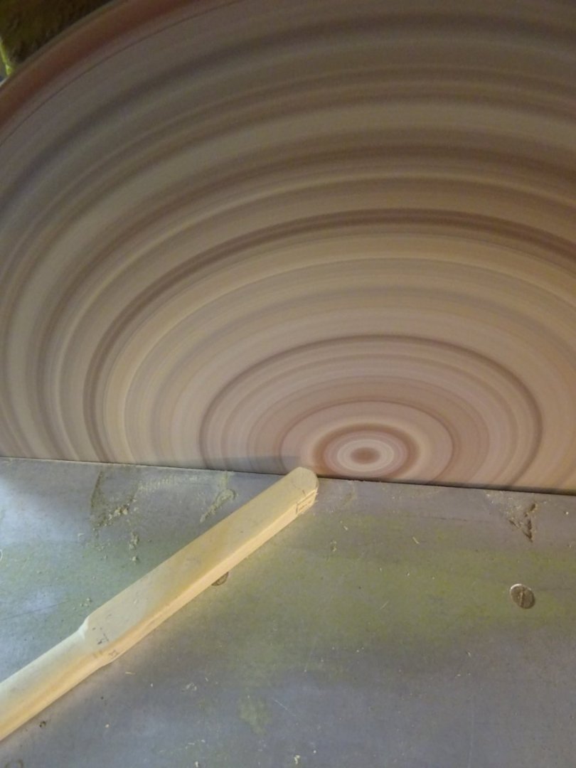
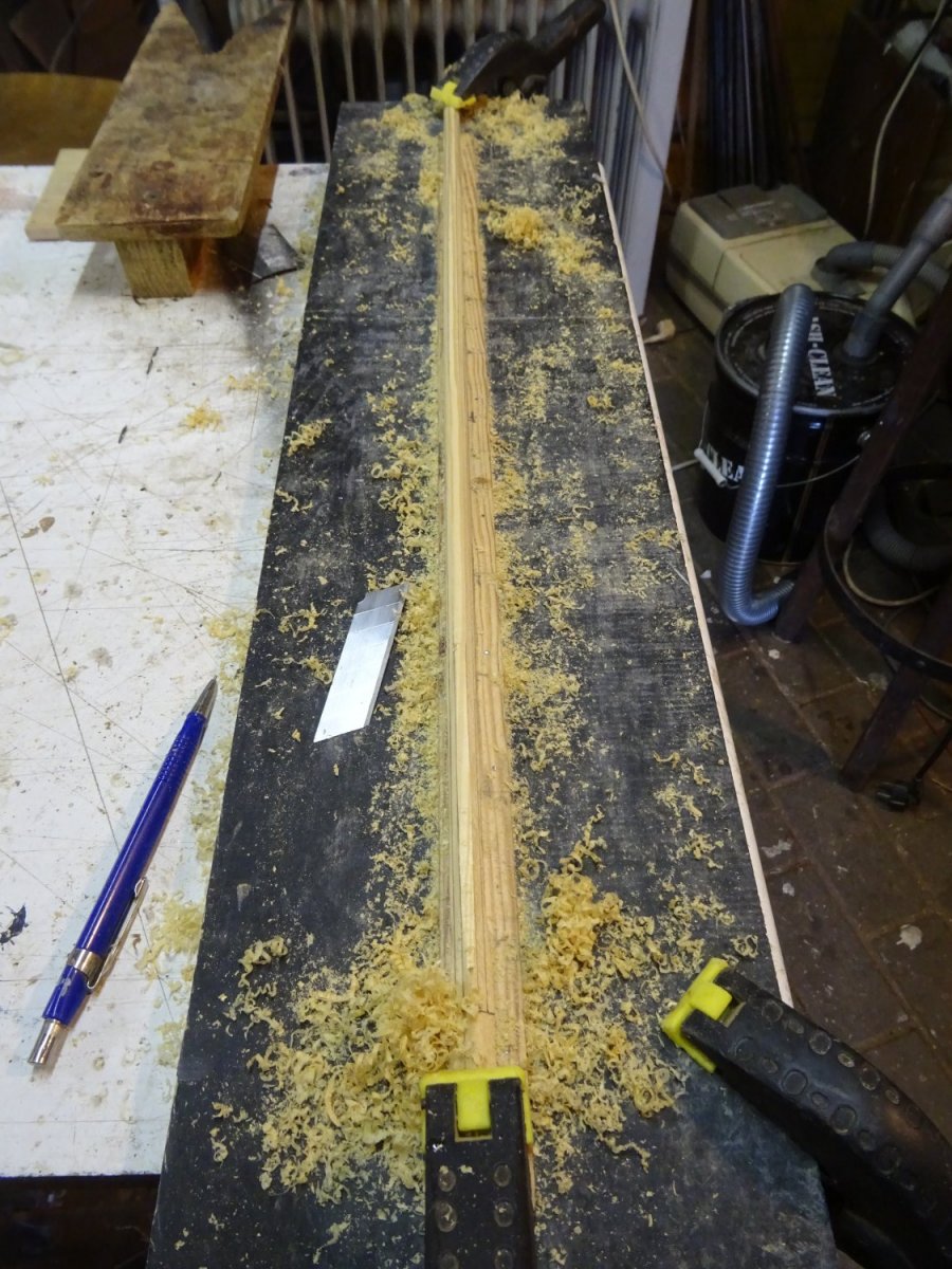
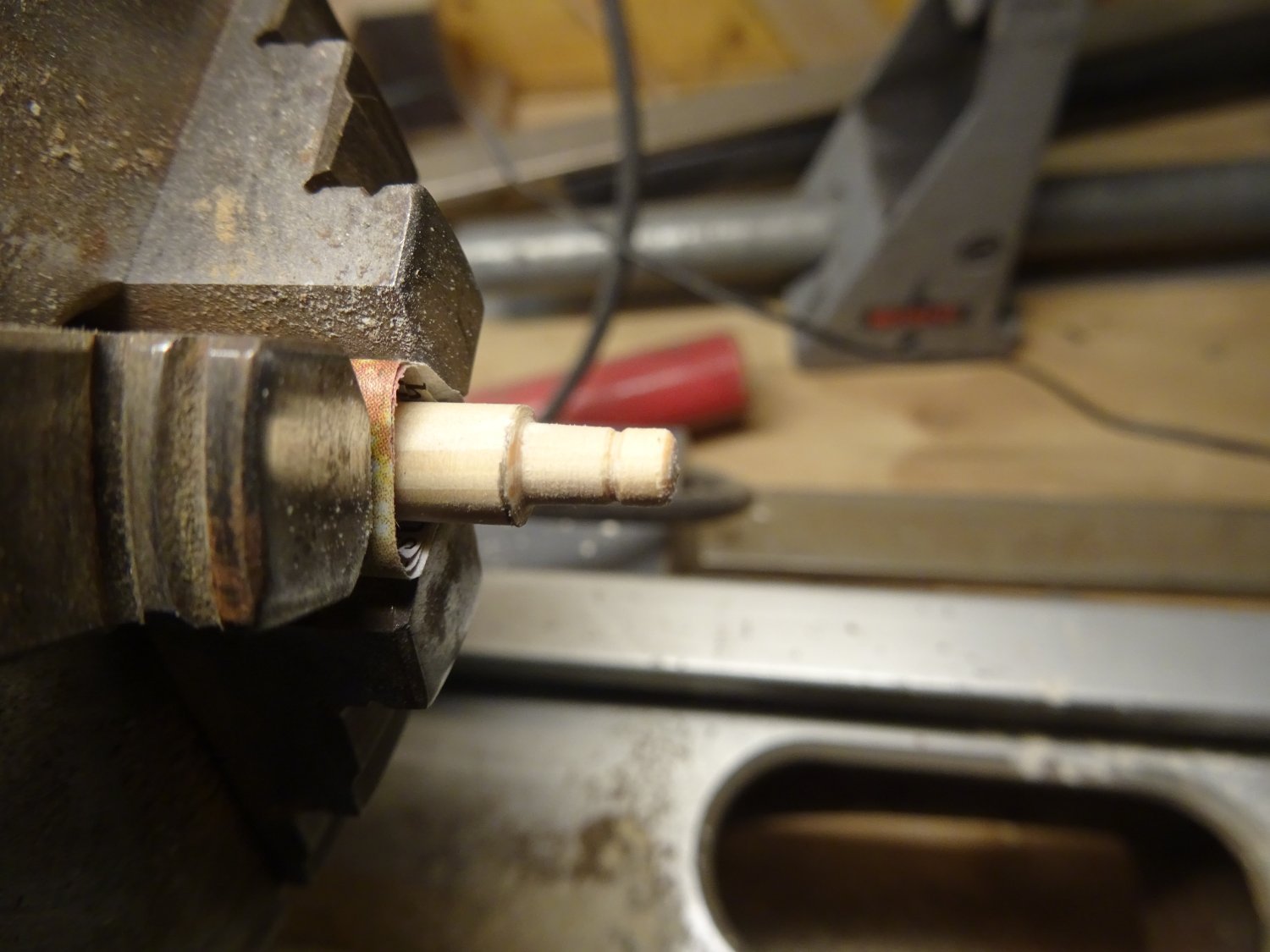
The mast is made in the same way as the jib boom. First I scrape it into an octagonal shape and then I sand it around.

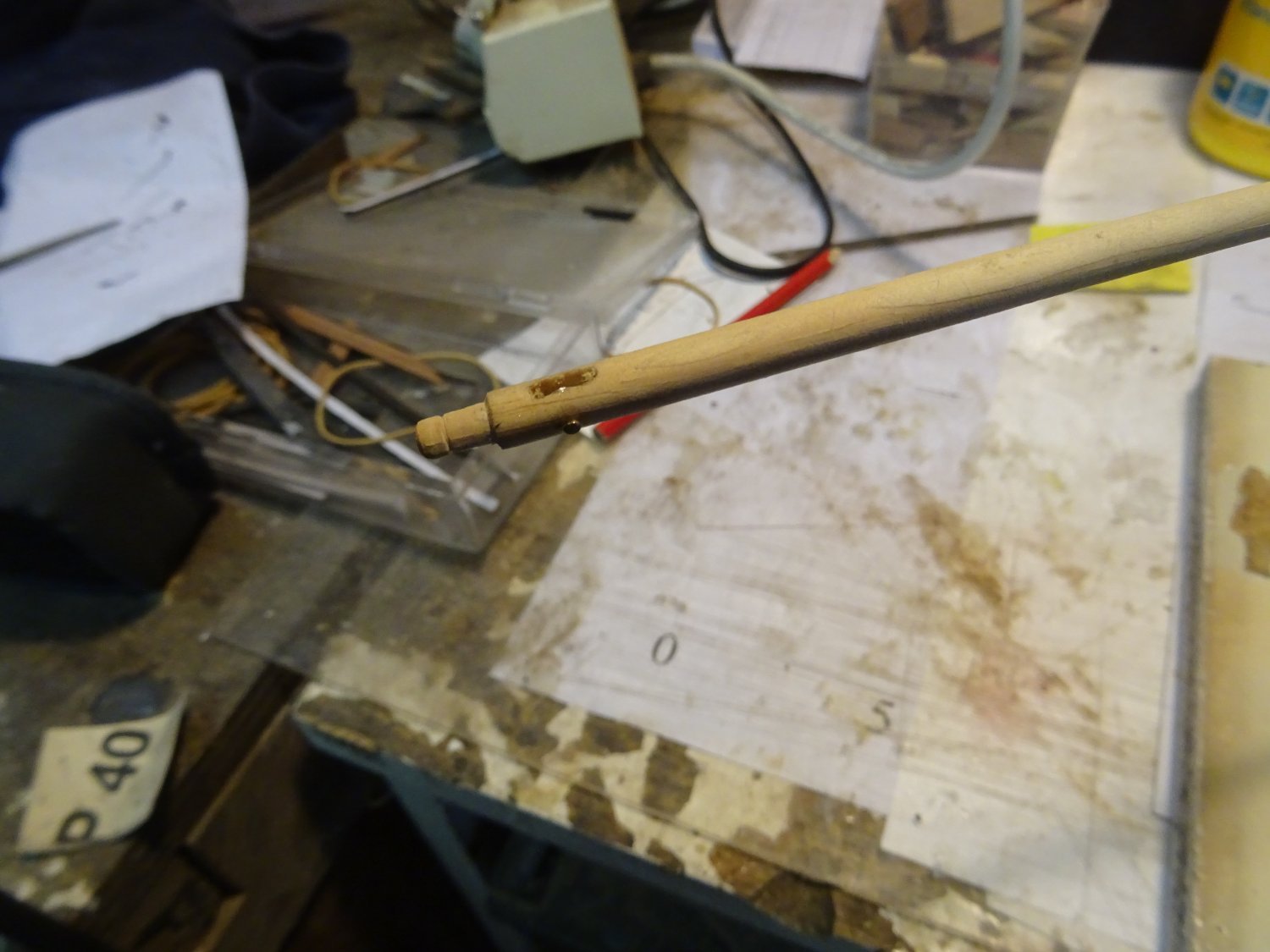
The top of the mast narrows in two steps. I make the tapers using the lathe.
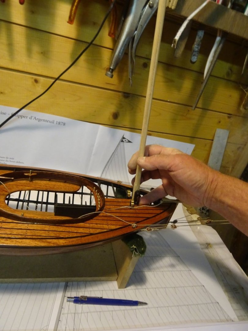
Fitting the mast in the tabernacle.
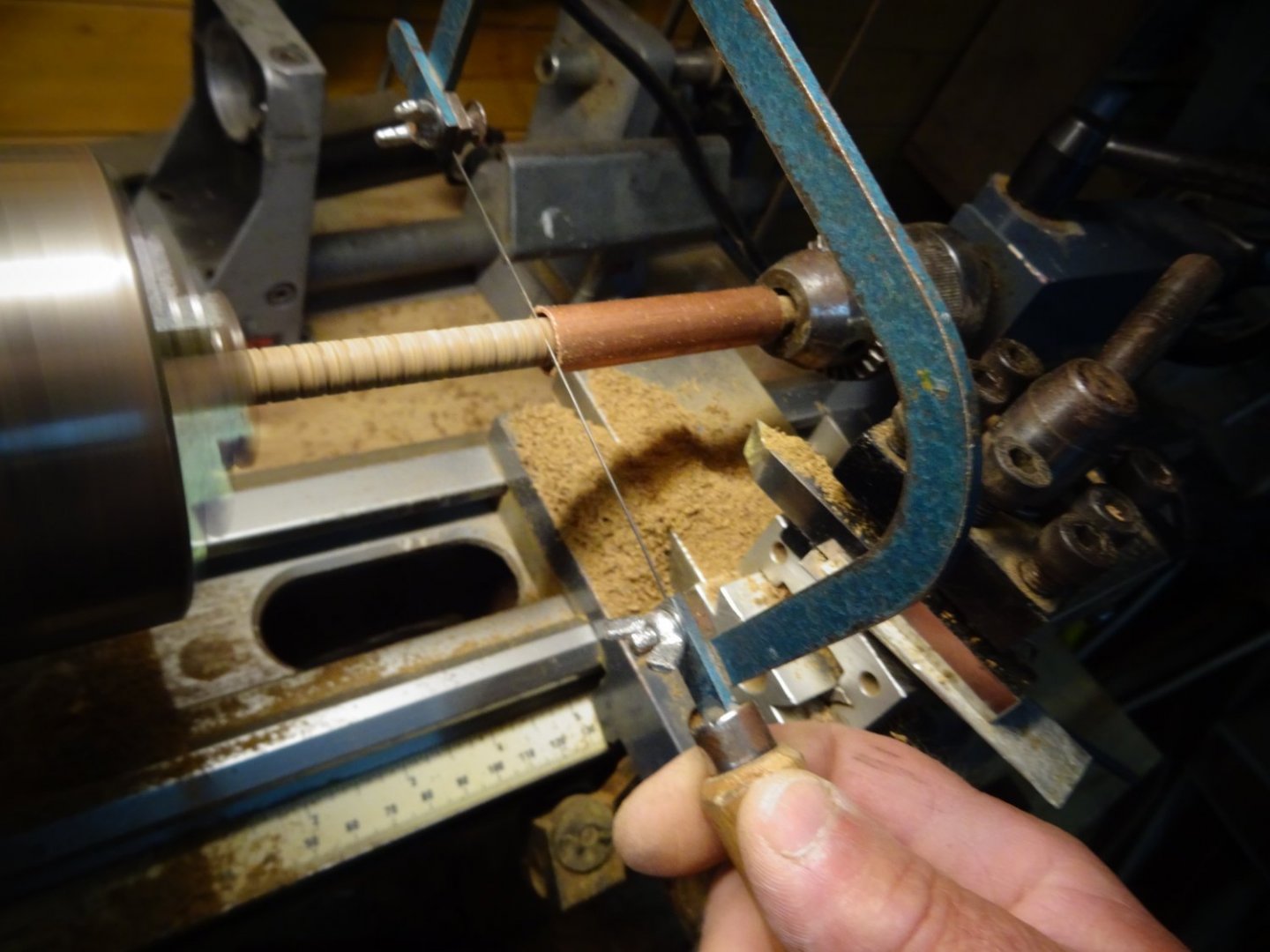
I sand the mast step around where the sheaves have to be placed.
The sheaves:

The mast, ready to be varnished. Two more sheaves are incorporated in the top and two mouse cleats have been fitted.

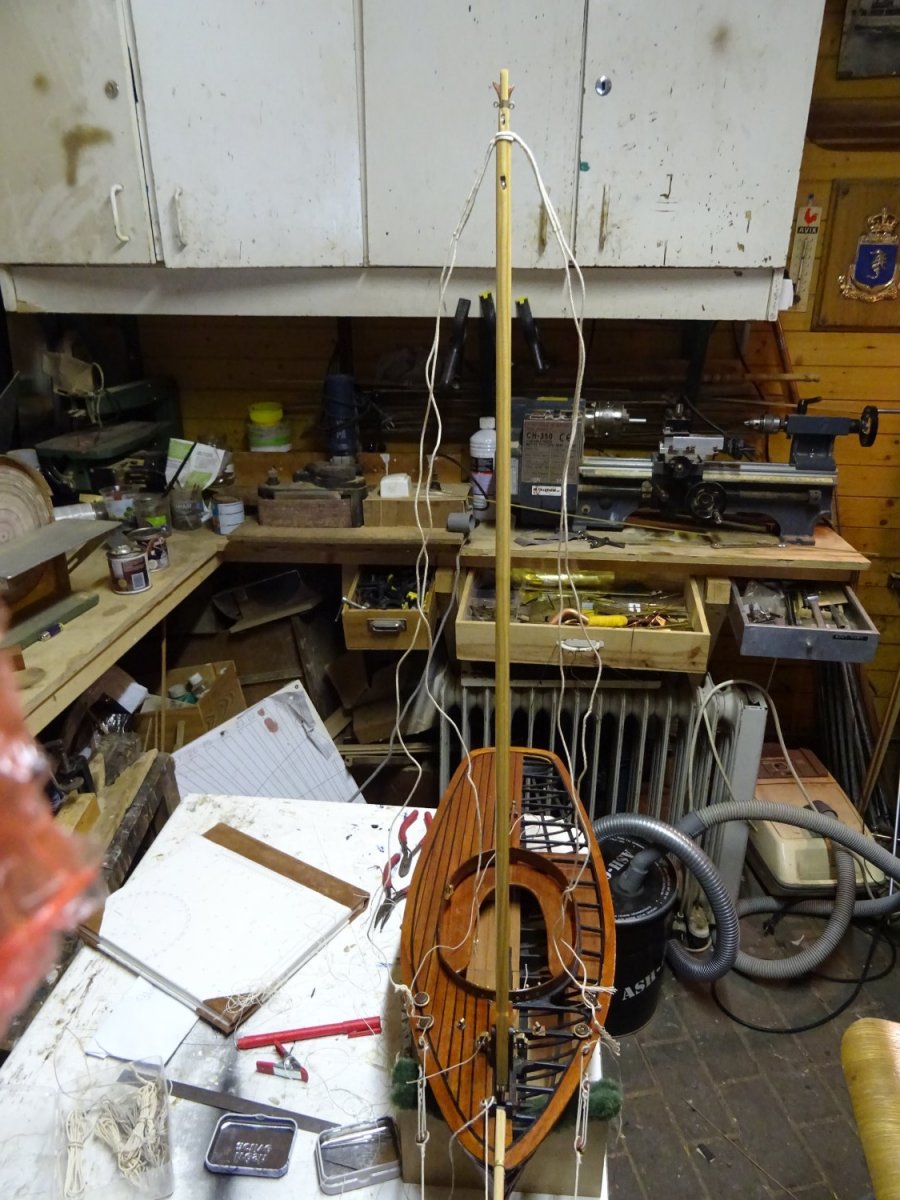
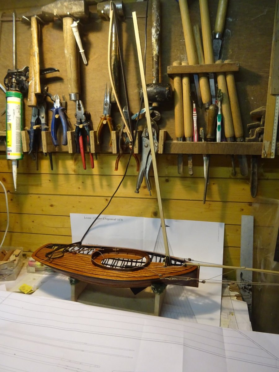
The mast on the model:
Thank you very much for reading this log and for your likes and for your constructive comments.
Till soon!
- GrandpaPhil, gsdpic, bolin and 10 others
-
13
-
On 1/23/2022 at 10:55 AM, wefalck said:
These boats had indeed a very lofty rig. There is not a loft of wind here in the Paris region and in addition the Bassin d'Argenteuil is surrounded by high trees (e.g. poplars as can be seen on many of the Impressionists' paintings). Plus, the main westerly wind direction is blanketed by the range of wills to the South and West of the river. I gather that these hills also make the winds blowing downwards with eddies forming in the valley. The Northern side is mostly flat, but the Seine has cut into the old flood-plain a few metres. Overall not a good sailing range, but it was easily accessible from Paris.
While in later years 'real' yachts with quite deep keel were sailed on the Bassin, a boat with a drop-keel and 'live' ballast is more appropriate for a river, such as the Seine. This limits how high you can make the rig in order to not create a too big fulcrum - although a high rig might catch more wind in the valley. I gather that is is why they extended the length of the rig, in order to be able to set more sail. During races these boats needed quite a bit of live ballast. I seem to remember seeing photographs that showed four people on board, but I don't remember, whether sandbags were still used on the Clippers.
Nice 'iron'-work on the bowsprit, btw 👍
Thanks for the compliment. Also nice to get some information about the sailing area from someone with local knowledge.
On 1/23/2022 at 11:25 AM, KeithAug said:Quite a complicated bowsprit rig, very interesting. I'm not sure it is a boat for a squall?
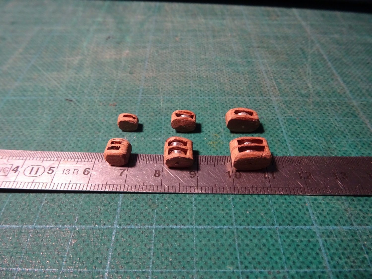
Thank you for the block size details. I need to make many in 3 sizes
large 7mm,
medium 6mm,
small 5mm.
Looks like being a lot of fun but i will need to think about simplicity of production.
Thanks Keith. Knowing your sense of detail, your blocks will be more detailed than mine.
-
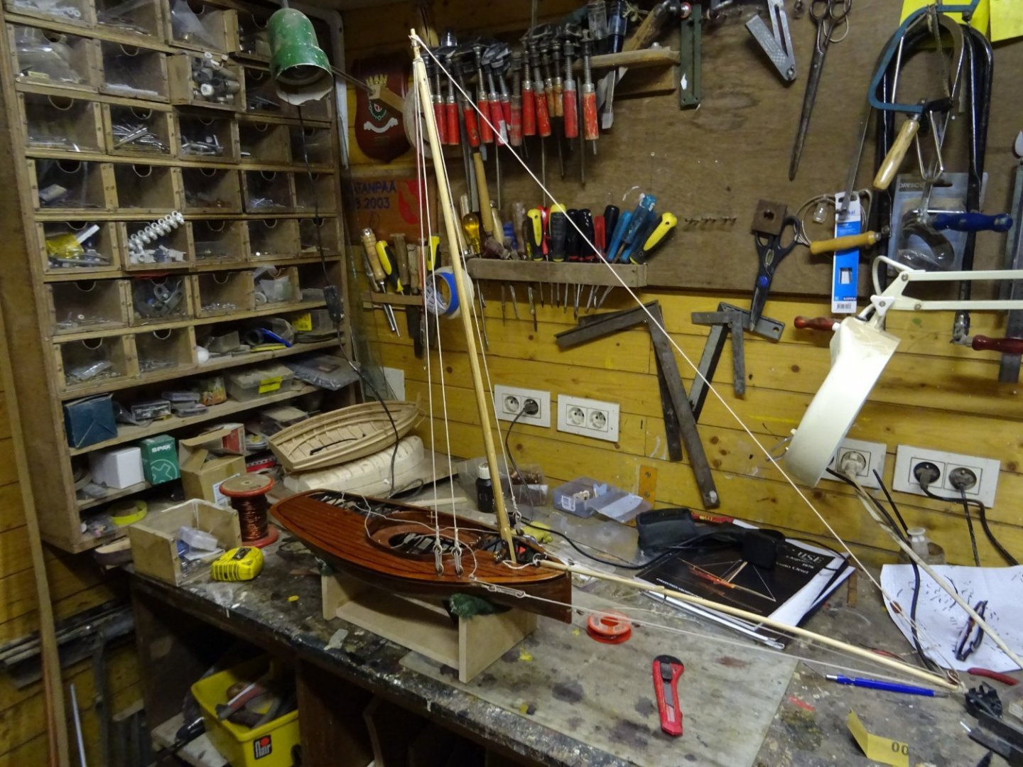
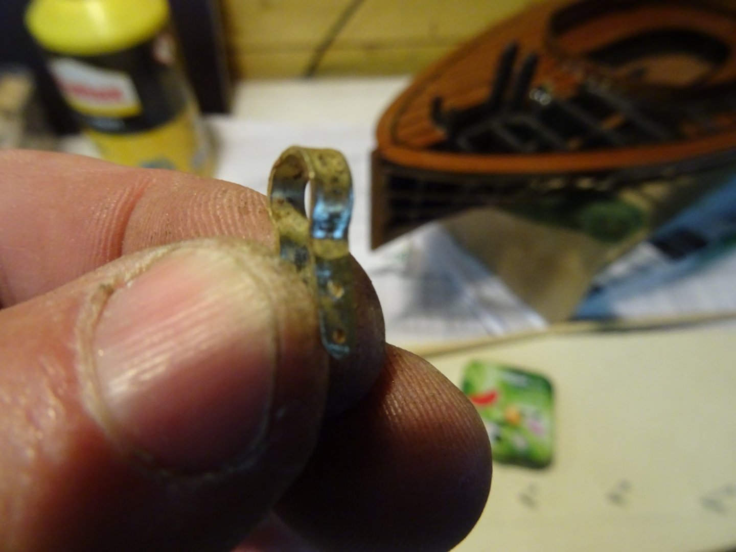
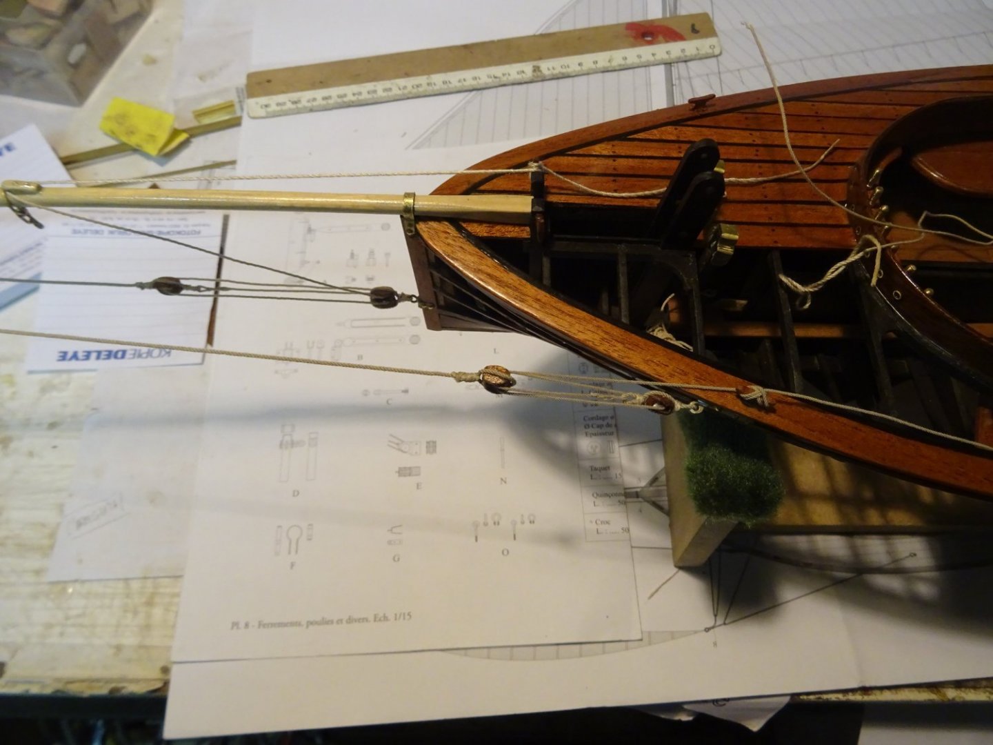
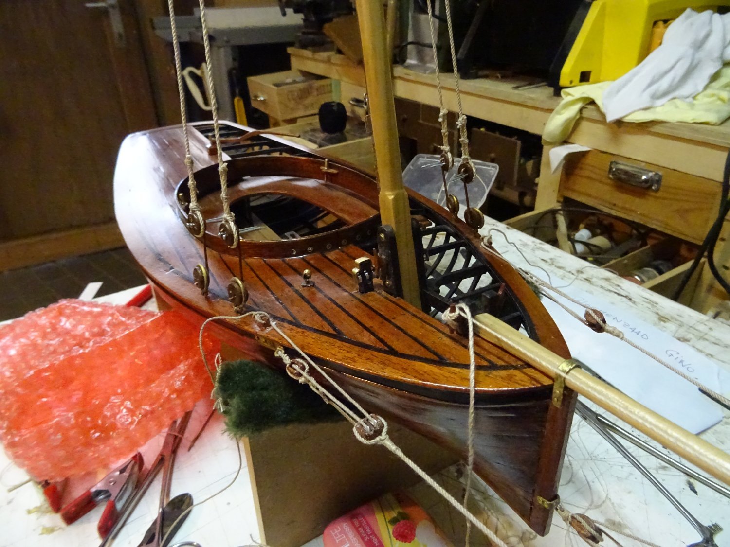
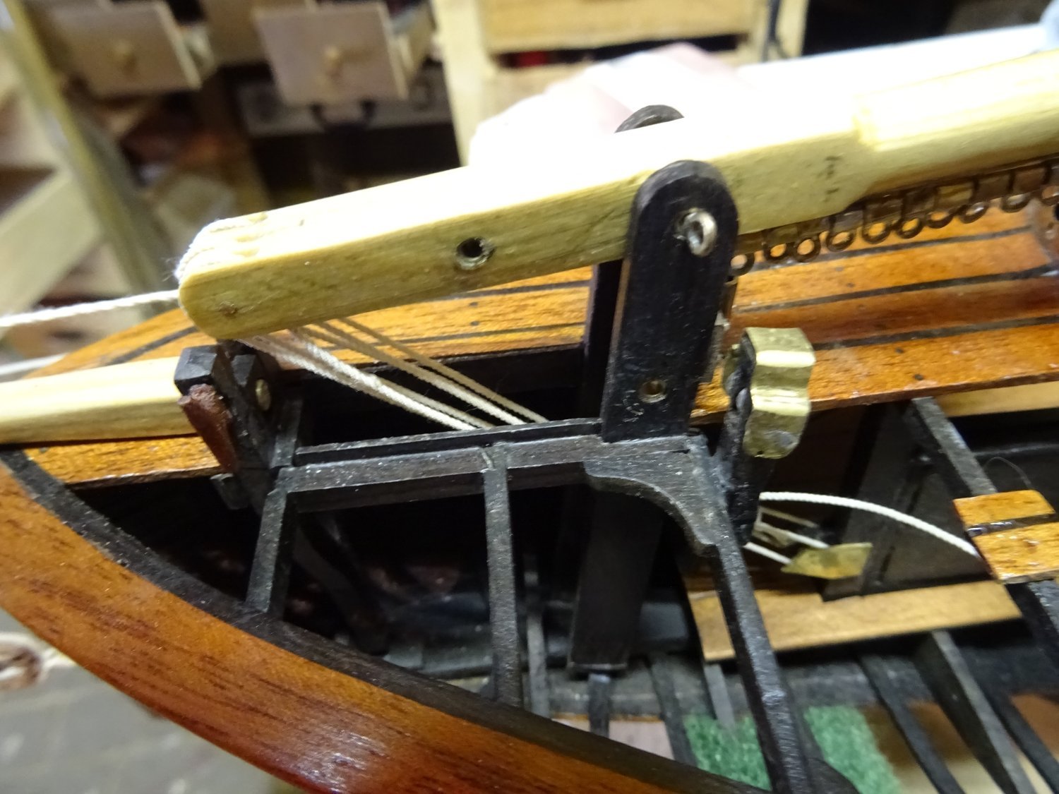
After the bowsprit is varnished and dry, it can be rigged.
In addition to the securing tap in the bits, the bowsprit is also held in place with a metal ring over the bow.
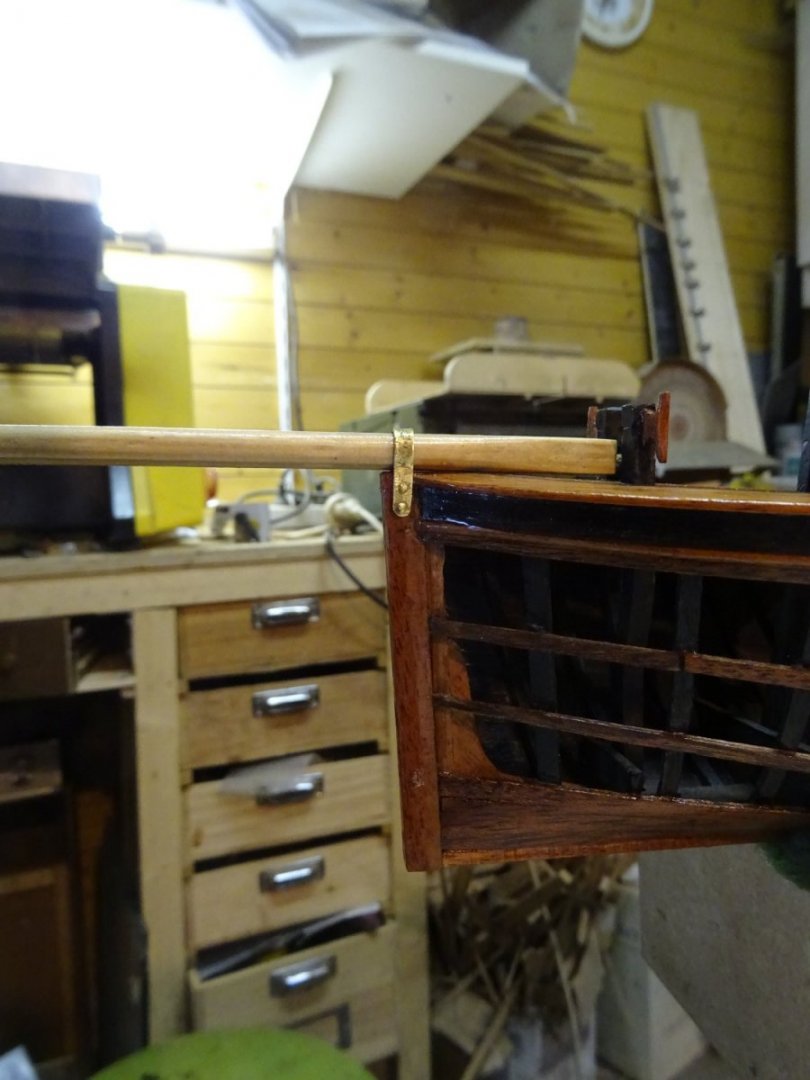
Before rigging the bowsprit, the jib traveler must first be made and placed.

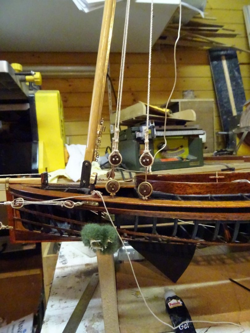
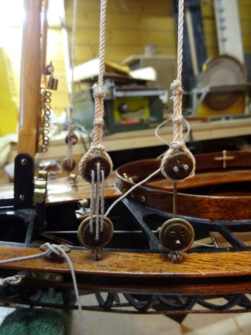
The bowsprit is also supported by three pulley systems, one amidships, one on the port side and one on the starboard side. I suppose pulley systems are used here to allow for trimming the bowsprit for each regatta.
For the midship pulley system, a double block is placed just above the waterline on the bow.
a line with a noose over the top of the bowsprit and with a single block at the other end forms the second part of the pulley.

The rigging of the midship pulley.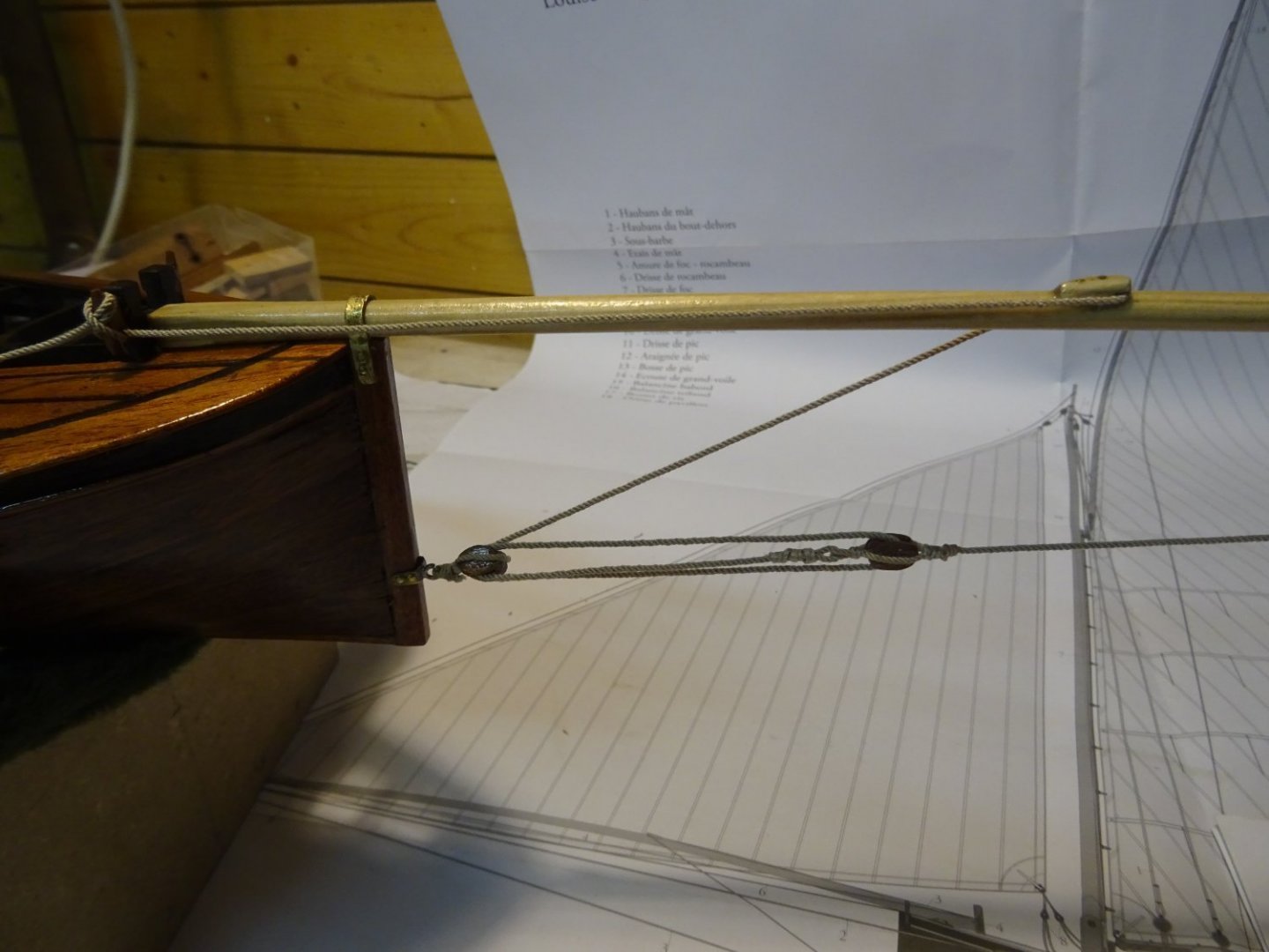
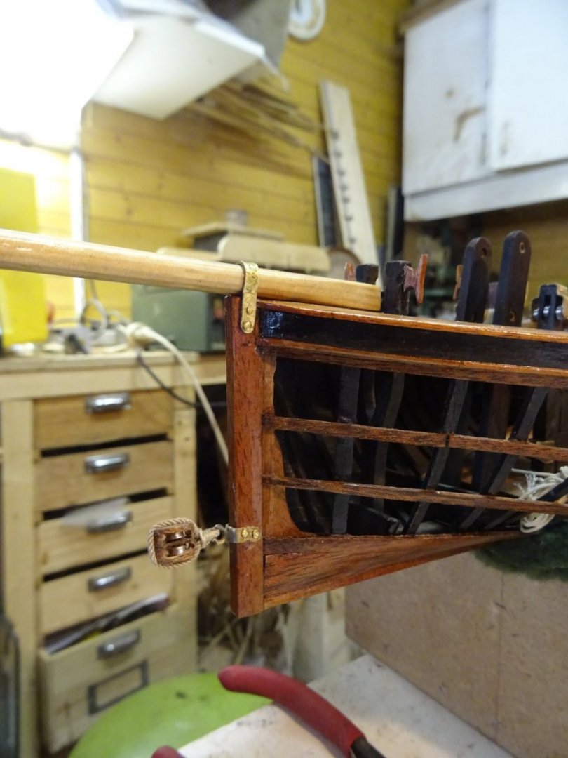
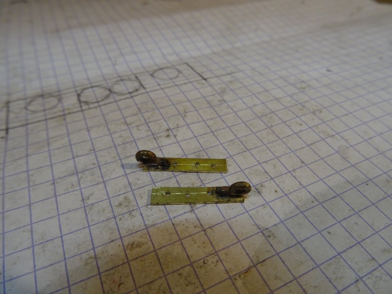
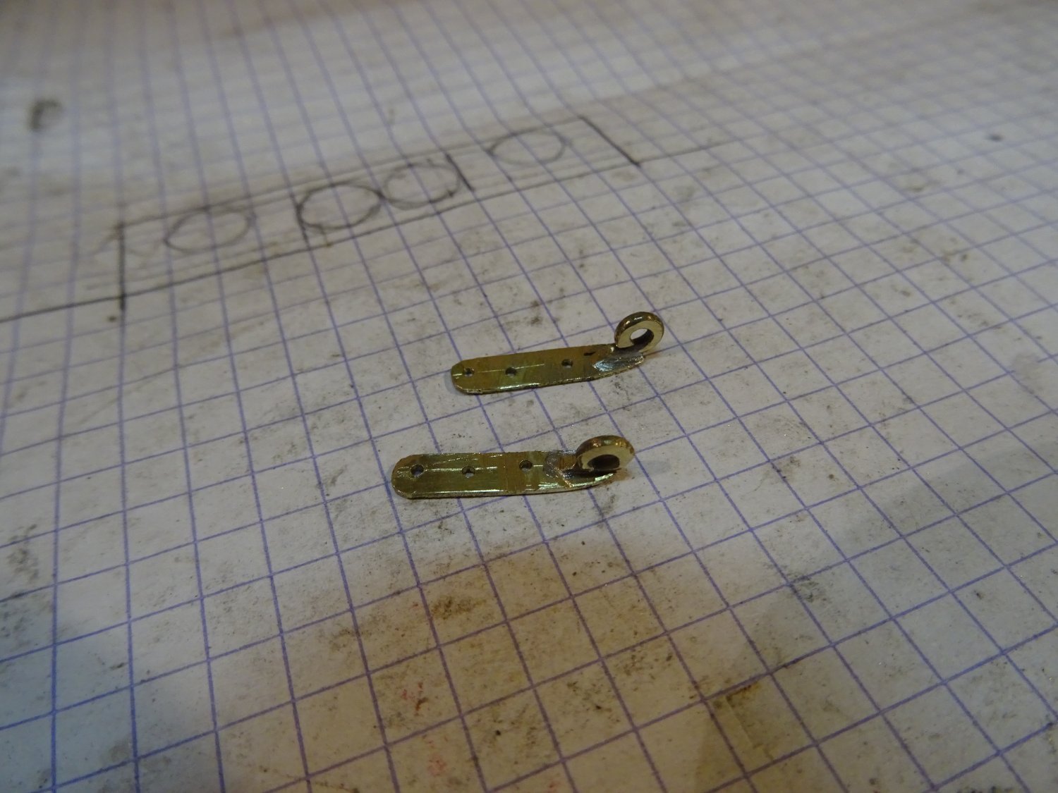
In addition to the midship pulley, the jib boom is also supported on the left and right by a pulley. The hoist is attached to the hull to an eye plate bolted to the wale.
Making the eye plate:
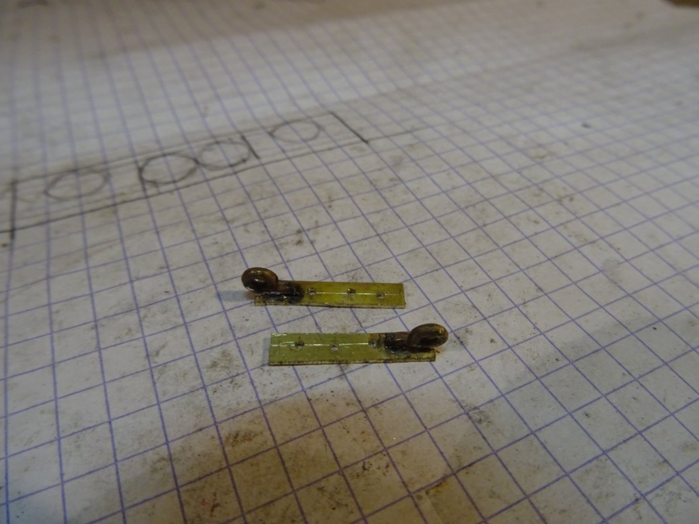

Rigging of the side pulleys: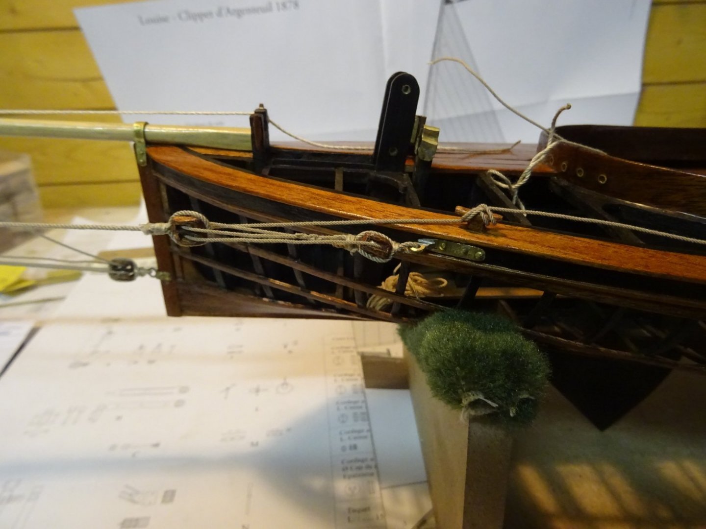

Thank you very much for reading this log and for your likes and for your constructive comments.
Till soon!
- Ekis, FriedClams, gsdpic and 10 others
-
13
-
On 1/15/2022 at 6:45 PM, KeithAug said:
Interesting process for making the blocks, they turned out very well. What are the dimensions for the 3 sizes please?
Hi Keith,
The big blocks: 10 mm
The medium blocks: 8 mm
The small blocks: 6 mm

The blocks still have to be provided with a strop. For some it is rope and for others metal. I'm waiting for the rigging to put them on and varnish the blocks
-
On 1/15/2022 at 6:35 PM, Wintergreen said:
That is a seriously long bowsprit! 😮
Looking good GL. 🙂
Thank you Hakan,
Yes, it is very long. My model has already become almost twice as long. There will be also a boom that extends far behind the model.
- mtaylor, BobG and Wintergreen
-
3
-
-
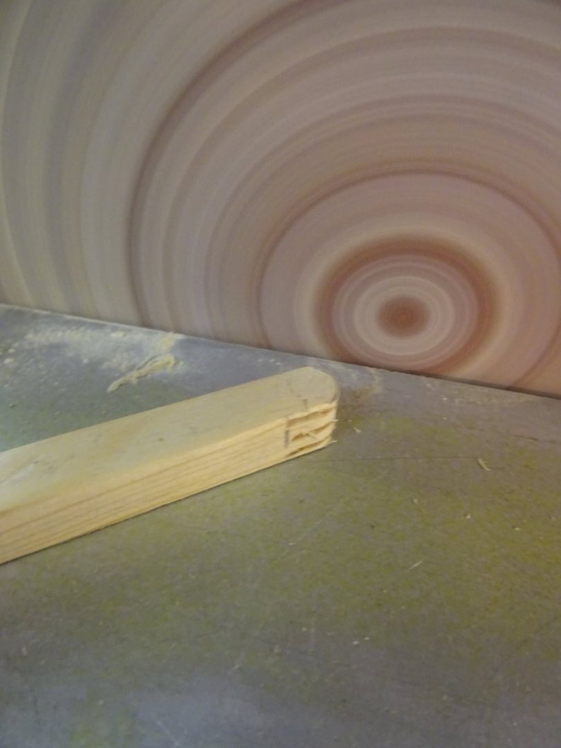
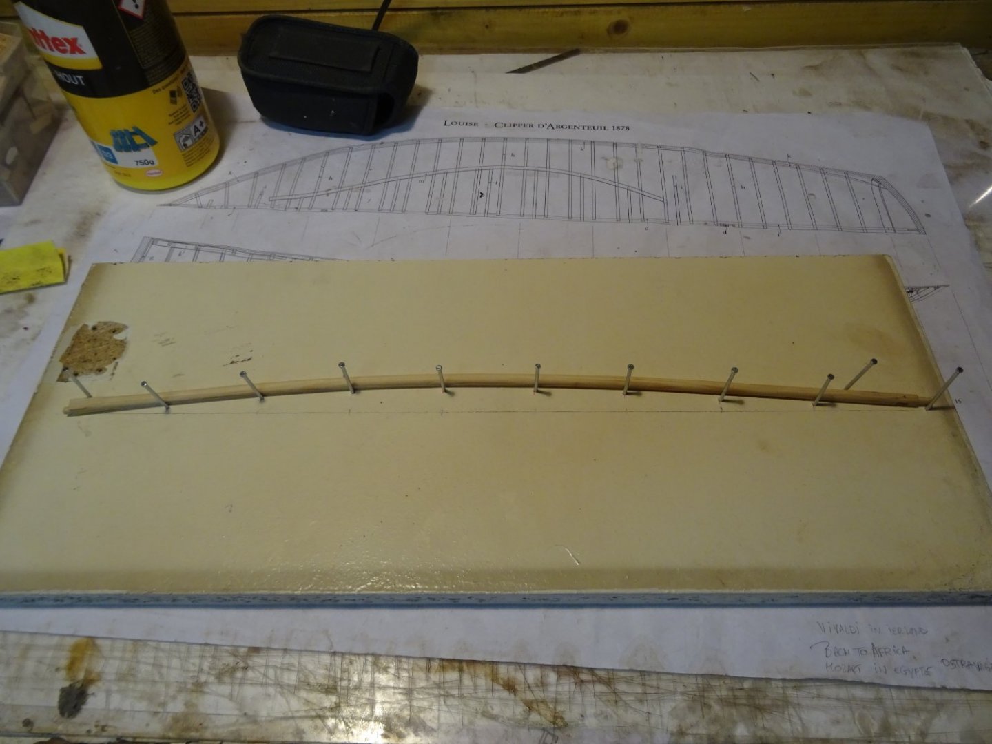
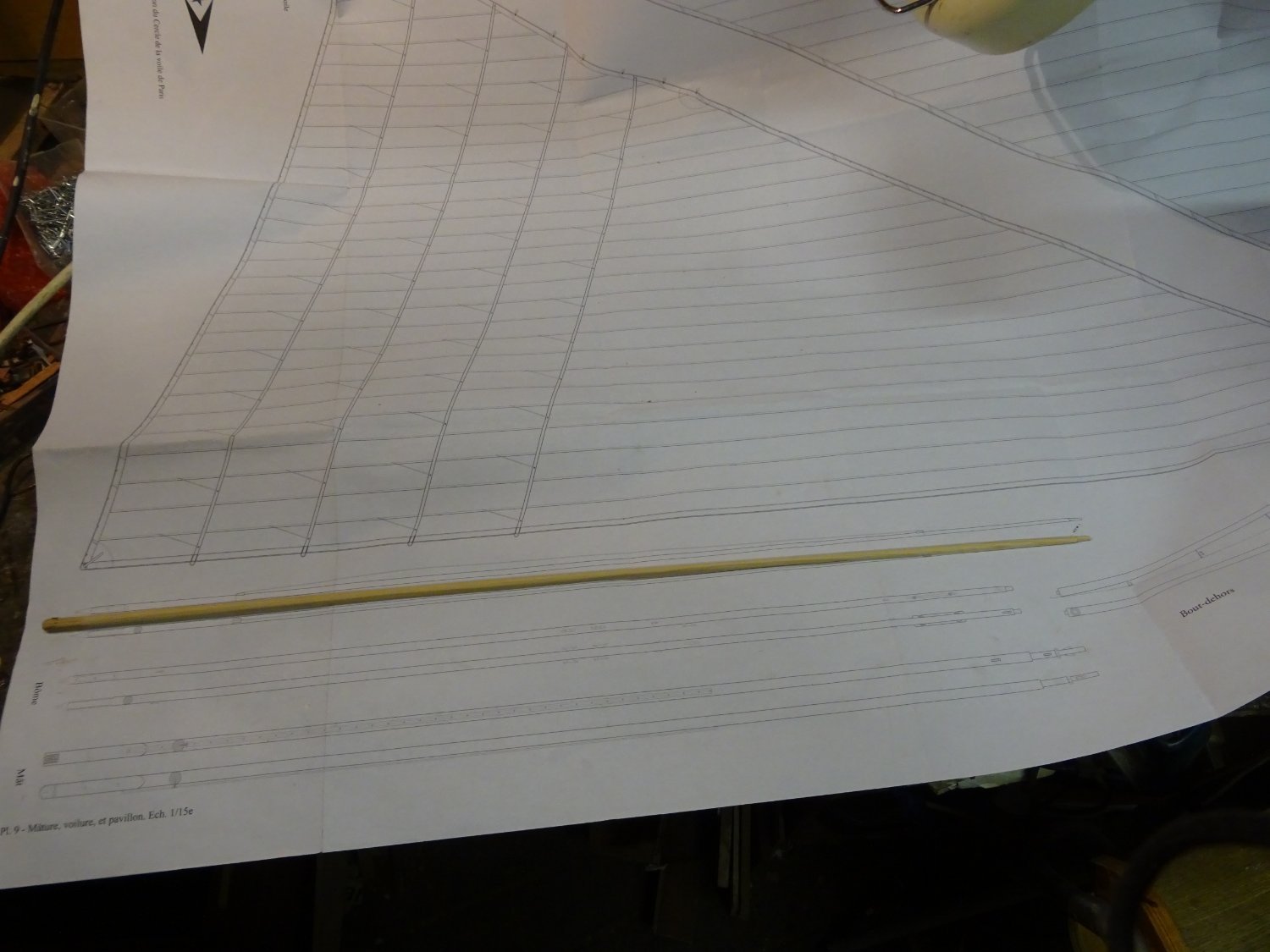
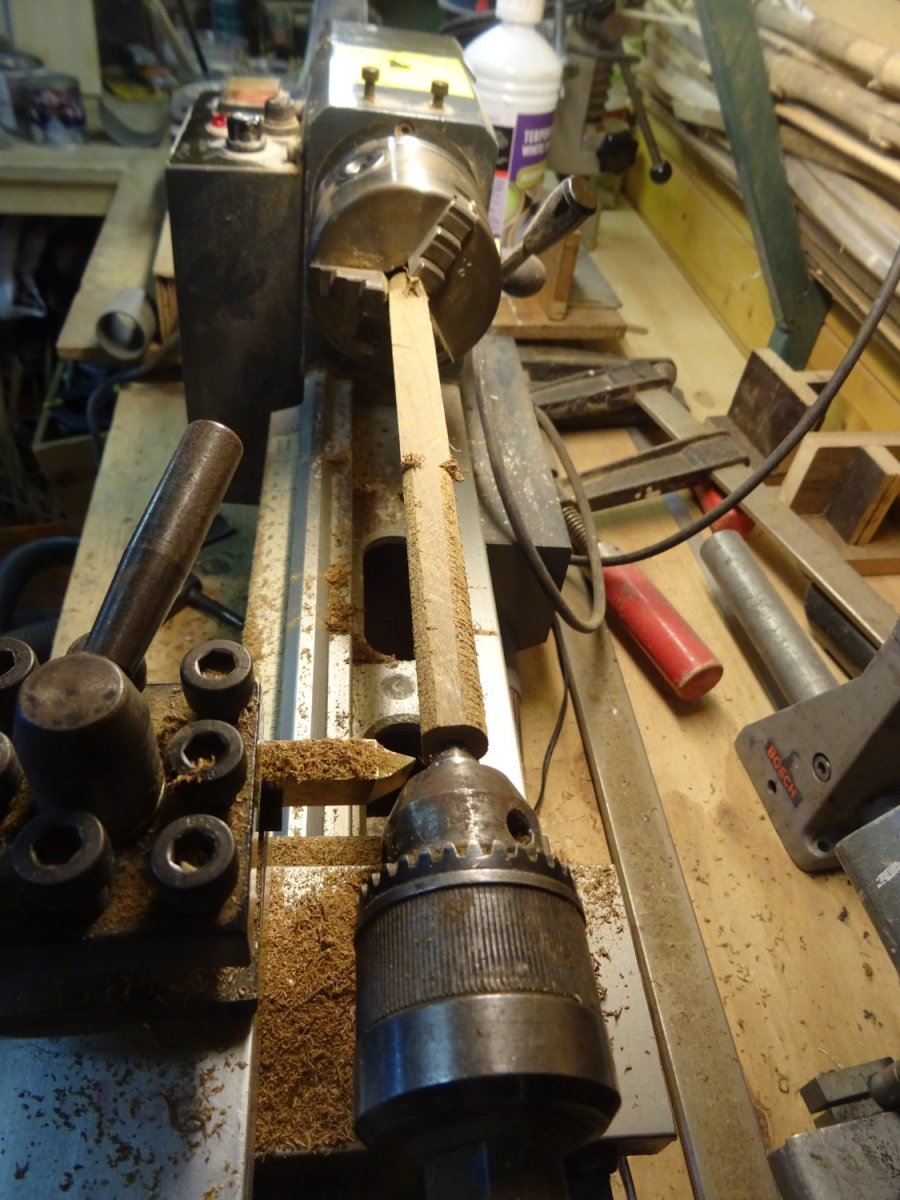
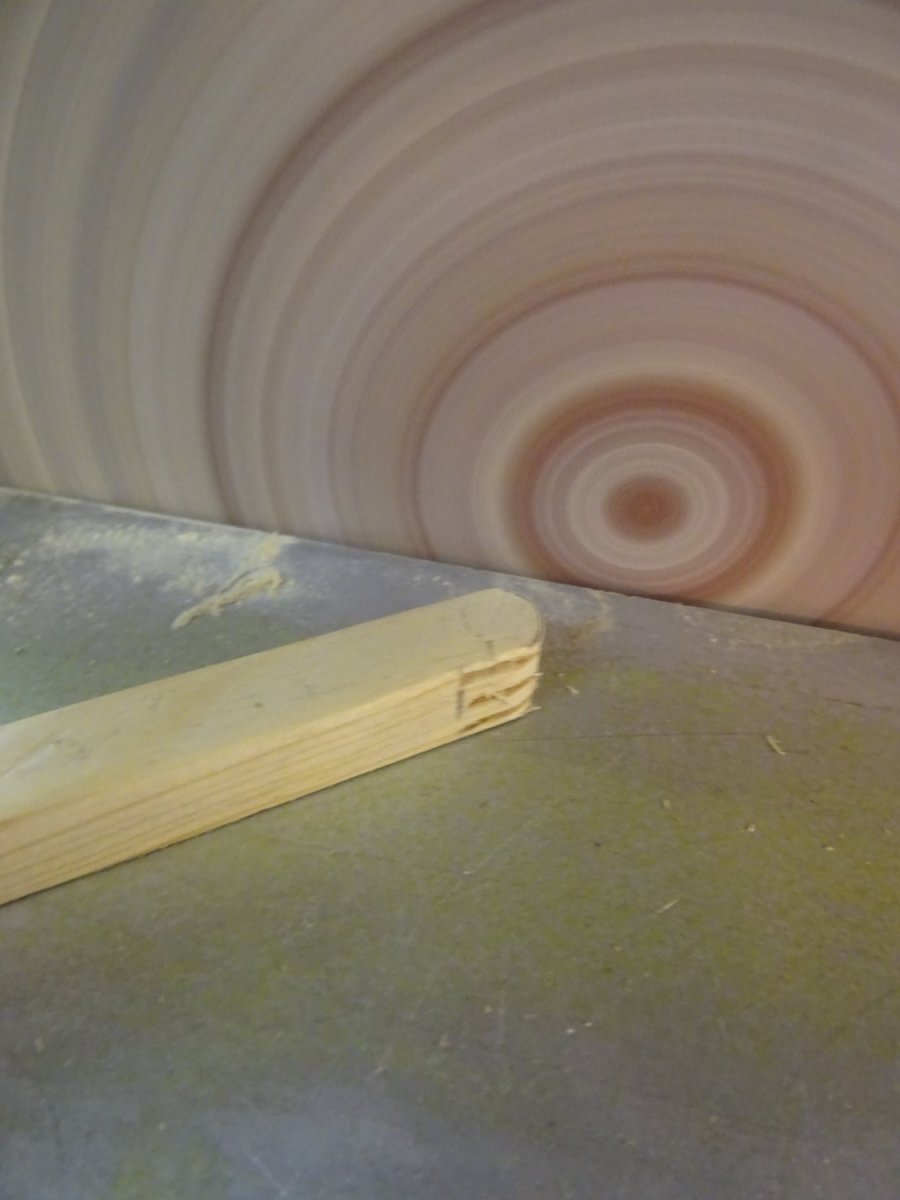
3. Bowsprit (jib boom)
The bowsprit is made of pine wood.
I start from a square piece.
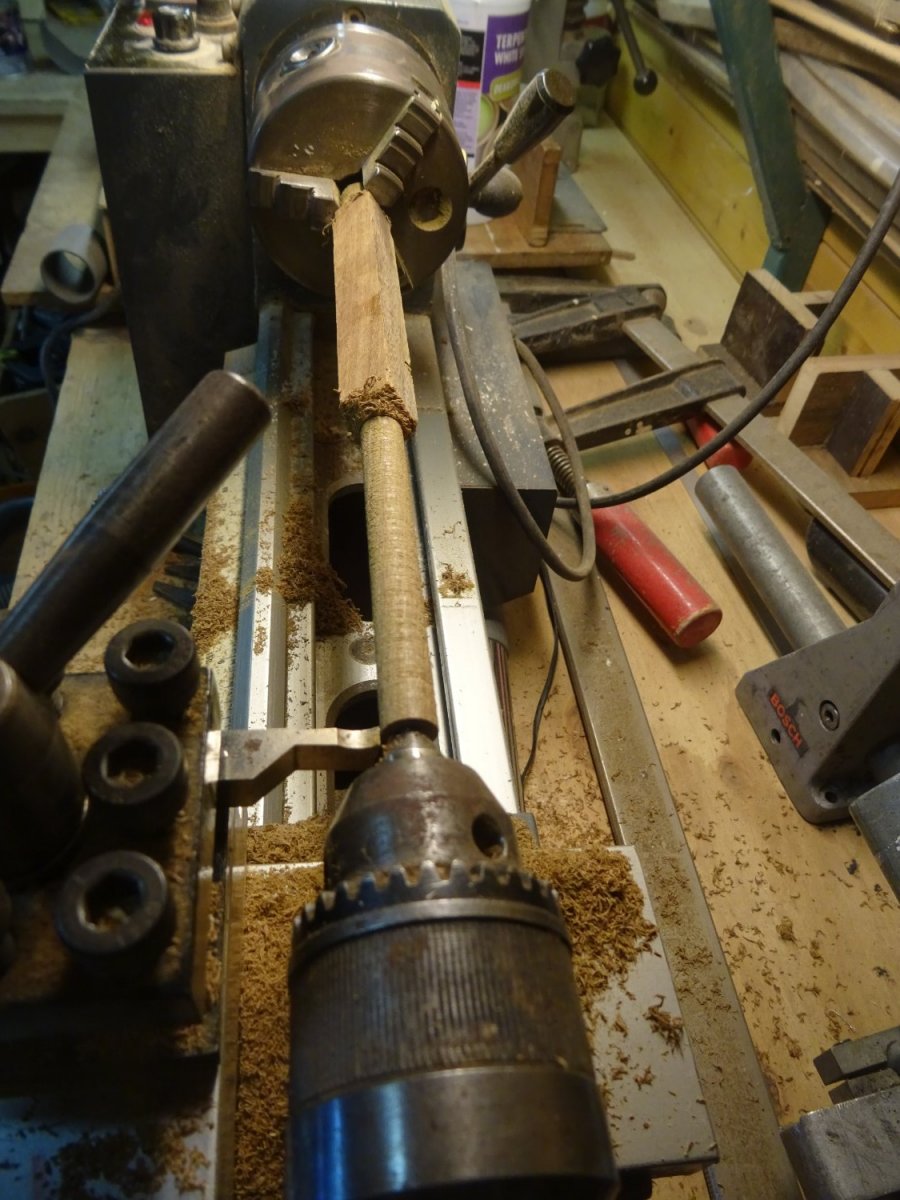
I scrape it into an octagonal shape first ...
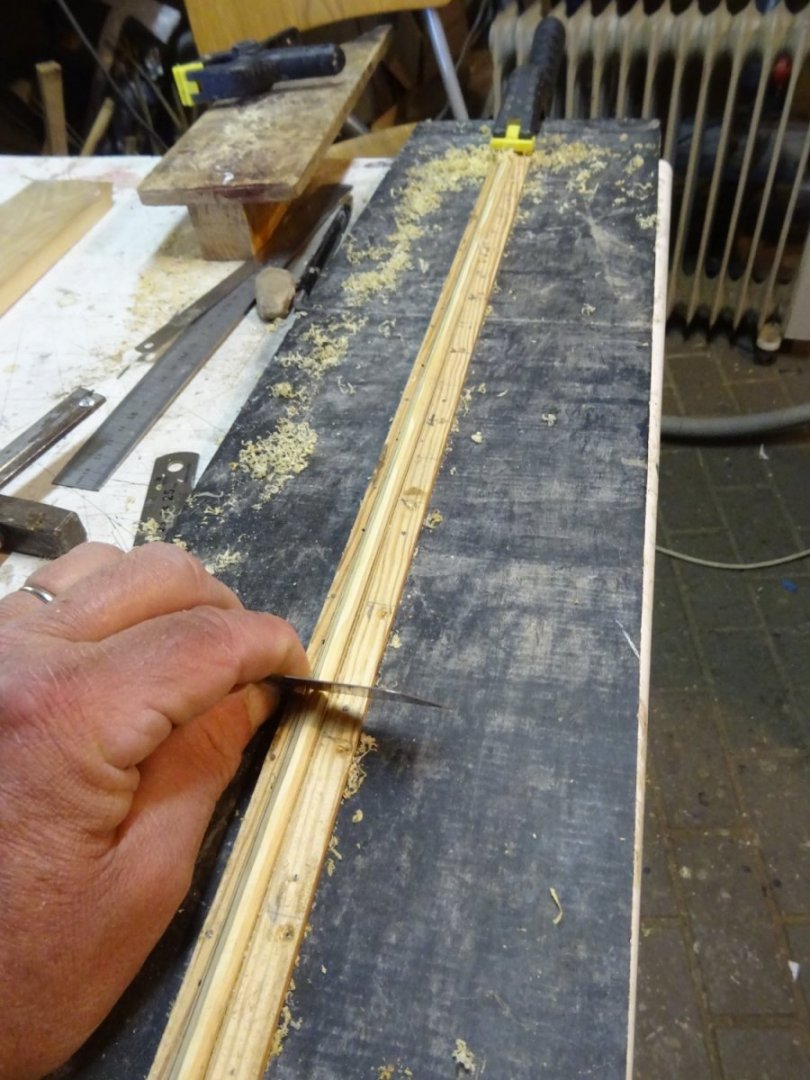
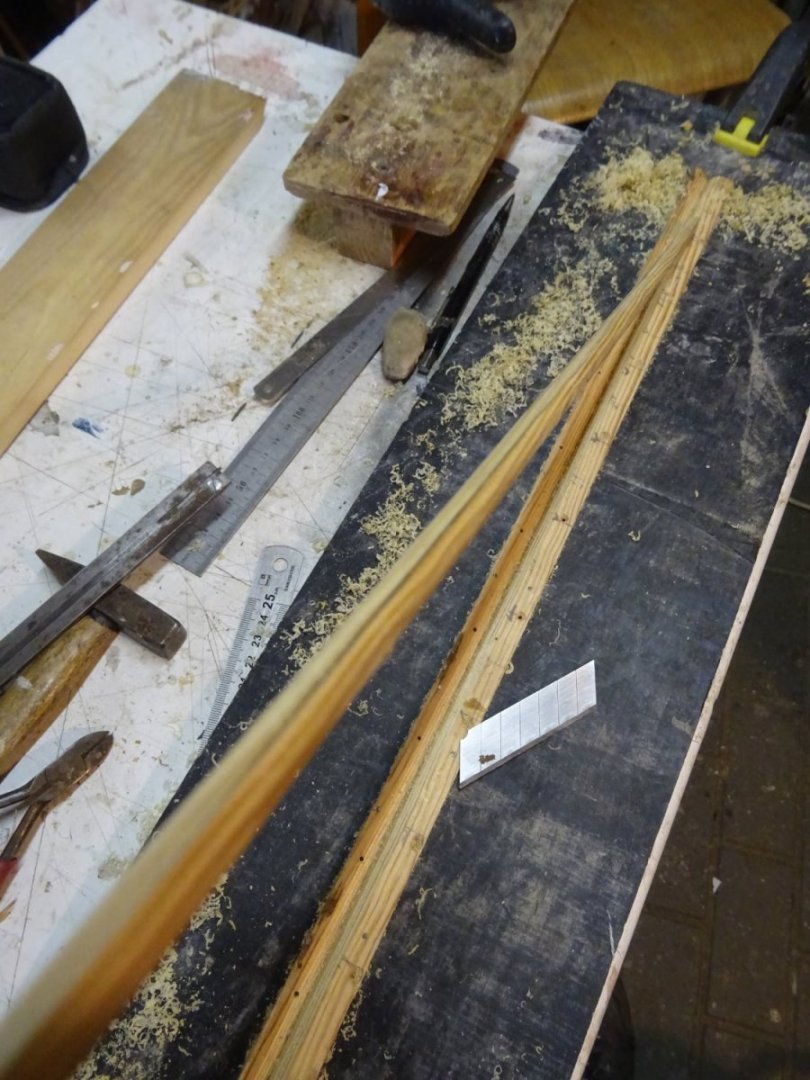
... and then sand it into round shape.
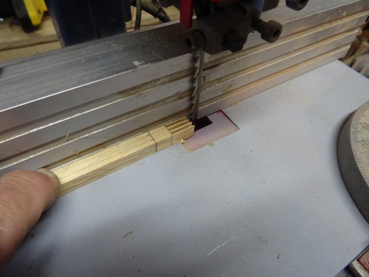
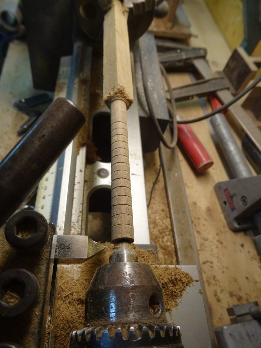
The very top of the bowsprit ends in a short thin part.
just behind that a slot is made in which the sheave for the jib traveler will be placed.

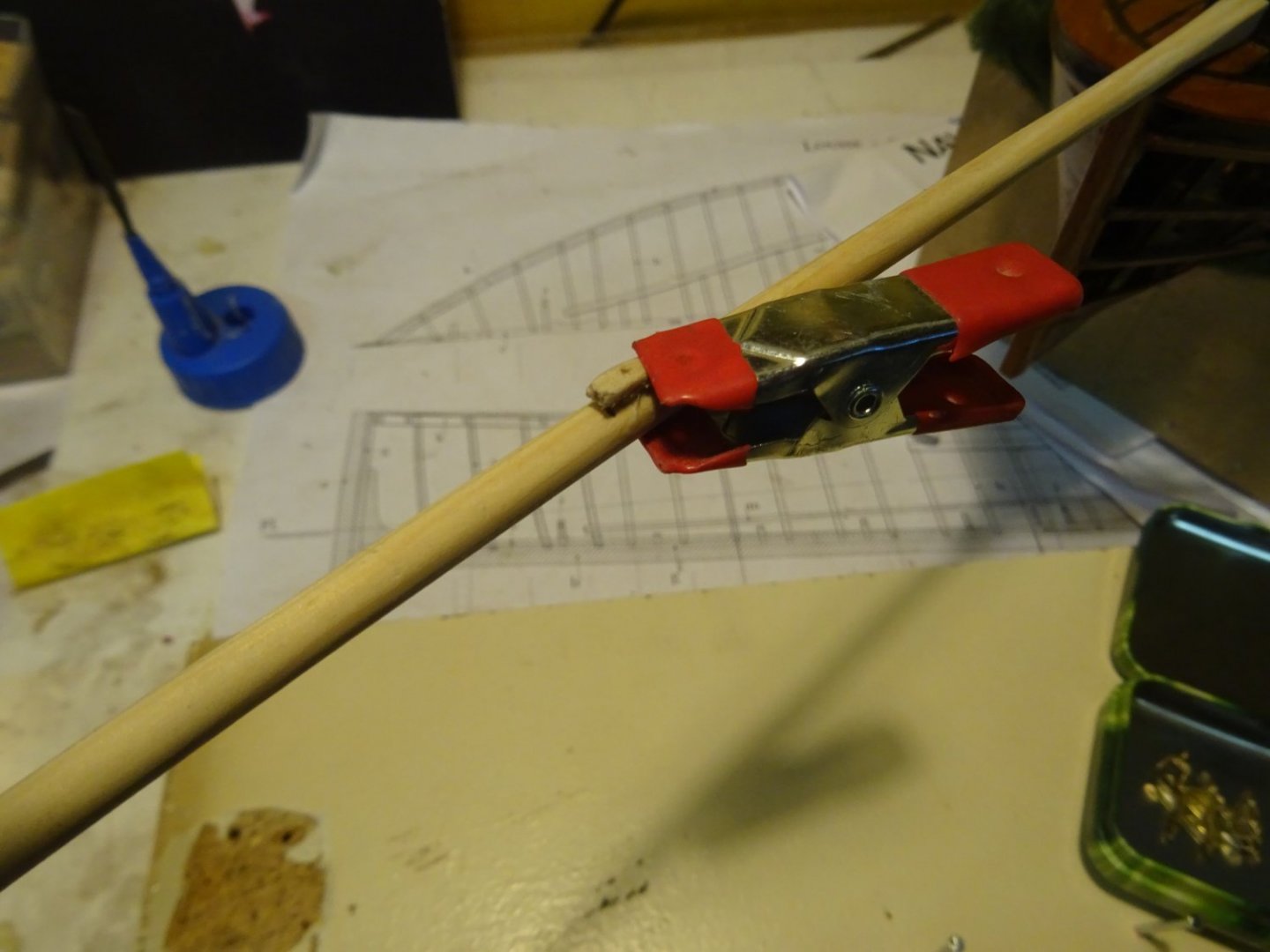
The bowsprit must be bent. So I wet it and place it in a simple jib for a few days to keep its curved shape.
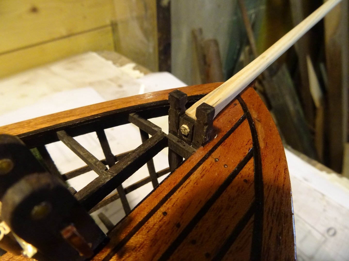
The heel of the bowsprit ends in a tap ...
... which secures it in the bits.
The sheave to operate the jib traveler.

On top of the bowsprit comes a mouse cleat.
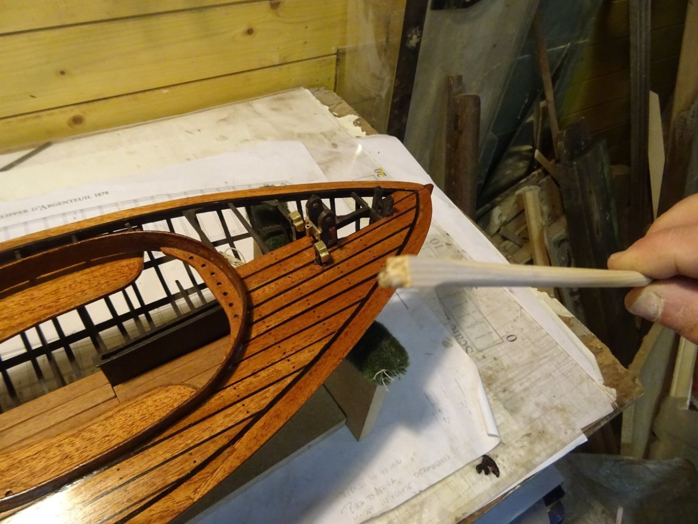
Fitting the bowsprit.
Thank you very much for reading this log and for your likes and for your constructive comments.
Till soon!
-
-
Very well done model, Hakan, congratulations.
Looking forward to your log of the Atlantica.- Wintergreen and mtaylor
-
2
-
13 hours ago, wefalck said:
(Grrr … this close-up show every speck of dust and all imperfections)
Imperfections? ... I only see perfection.
Beautiful work!
- FriedClams, mtaylor, mbp521 and 1 other
-
4
-
The start of a new project is always an exciting moment. I signed up to follow your log.
Zeer veel succes toegewenst (Wishing you a lot of success)!- Keith Black and dirkske
-
2
-
Hello Dirk, welcome to the MSW forum. Where in Belgium are you from?
- mtaylor, Keith Black, Ryland Craze and 1 other
-
4


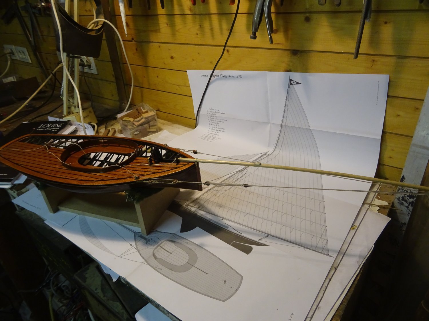


Clipper d'Argenteuil by G.L. - POF - scale 1/15 - SMALL
in - Build logs for subjects built 1851 - 1900
Posted
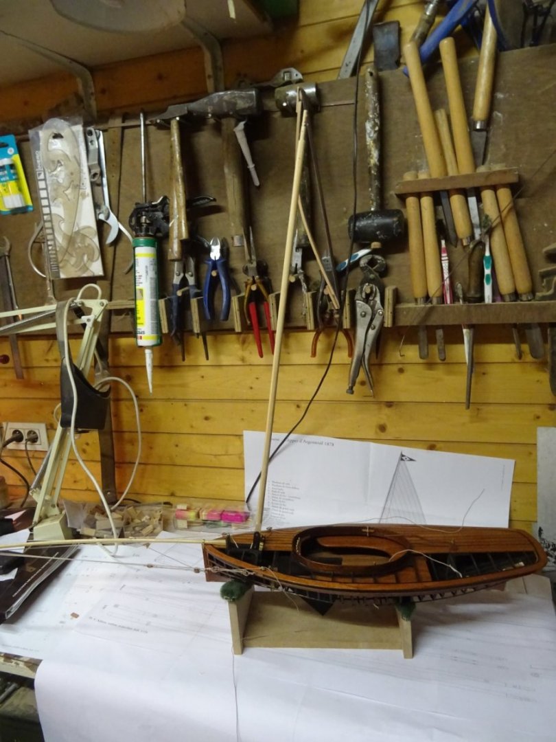
Hello Ekis,
The project is currently dormant. I rigged the mast and spars, but waited to put the sails on it because then the model would be almost impossible to transport by car. My intention was to first take the model to the model discussion of my modeling club. That happened in November last year.
In the meantime I have started a new project: a kind of triptych of the sloop that we used to row during our nautical training in the navy in the seventies. I want to build a rowing version and two sailing versions of it. The rowing version is now ready, I am now making the sails of the first sailing version. Unfortunately I didn't get around to writing about it on this forum.
But now to answer your question: Yes, I intend to finish the clipper. And the story on the forum will take its course. It just might take a while.