


G.L.
-
Posts
1,553 -
Joined
-
Last visited
Content Type
Profiles
Forums
Gallery
Events
Posts posted by G.L.
-
-
Looks perfect, Giampiero. Have you had the help of some spiders
-
What a relief! I was already afraid that you had crashed with your Fokker D VIII.
- mtaylor and aviaamator
-
 2
2
-
3. Keel, stem and rudderpost
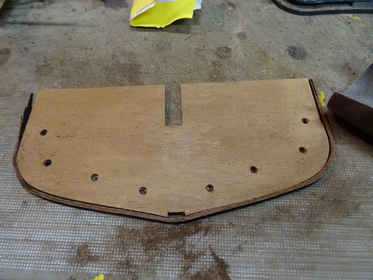
Before placing the frames definitively, the keelson has to be made.
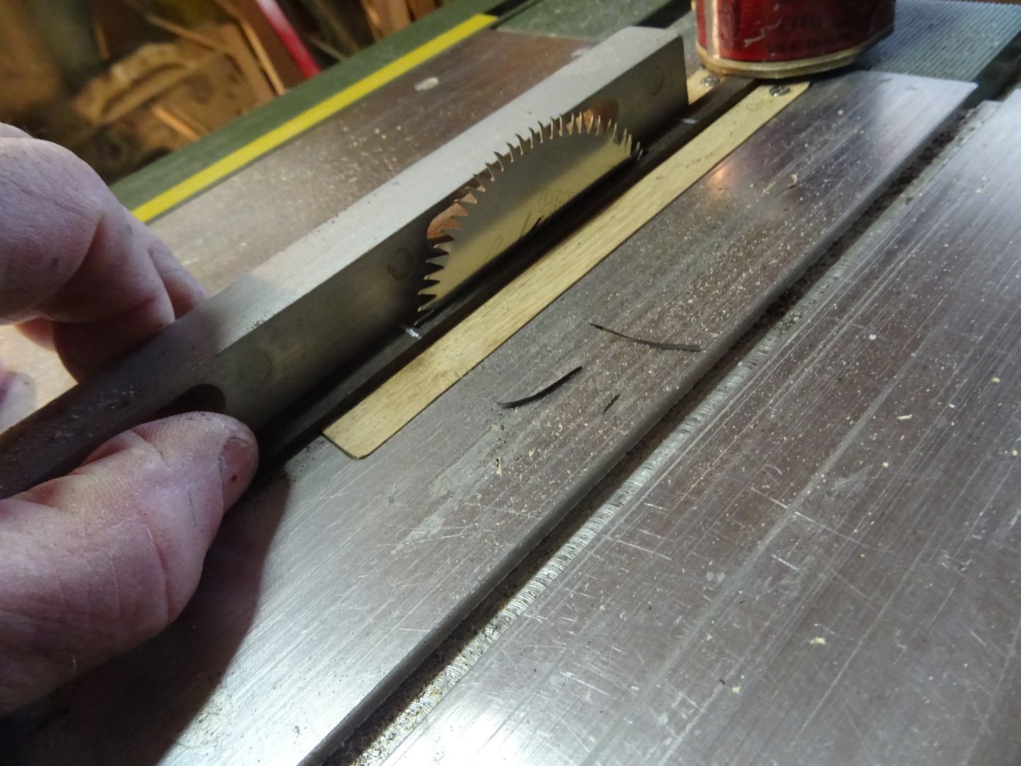
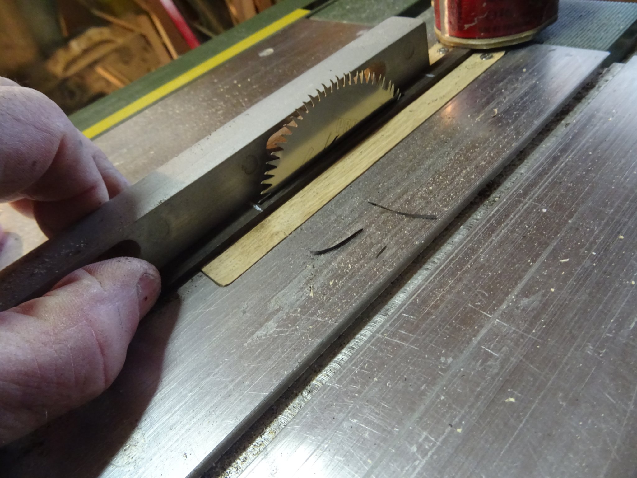
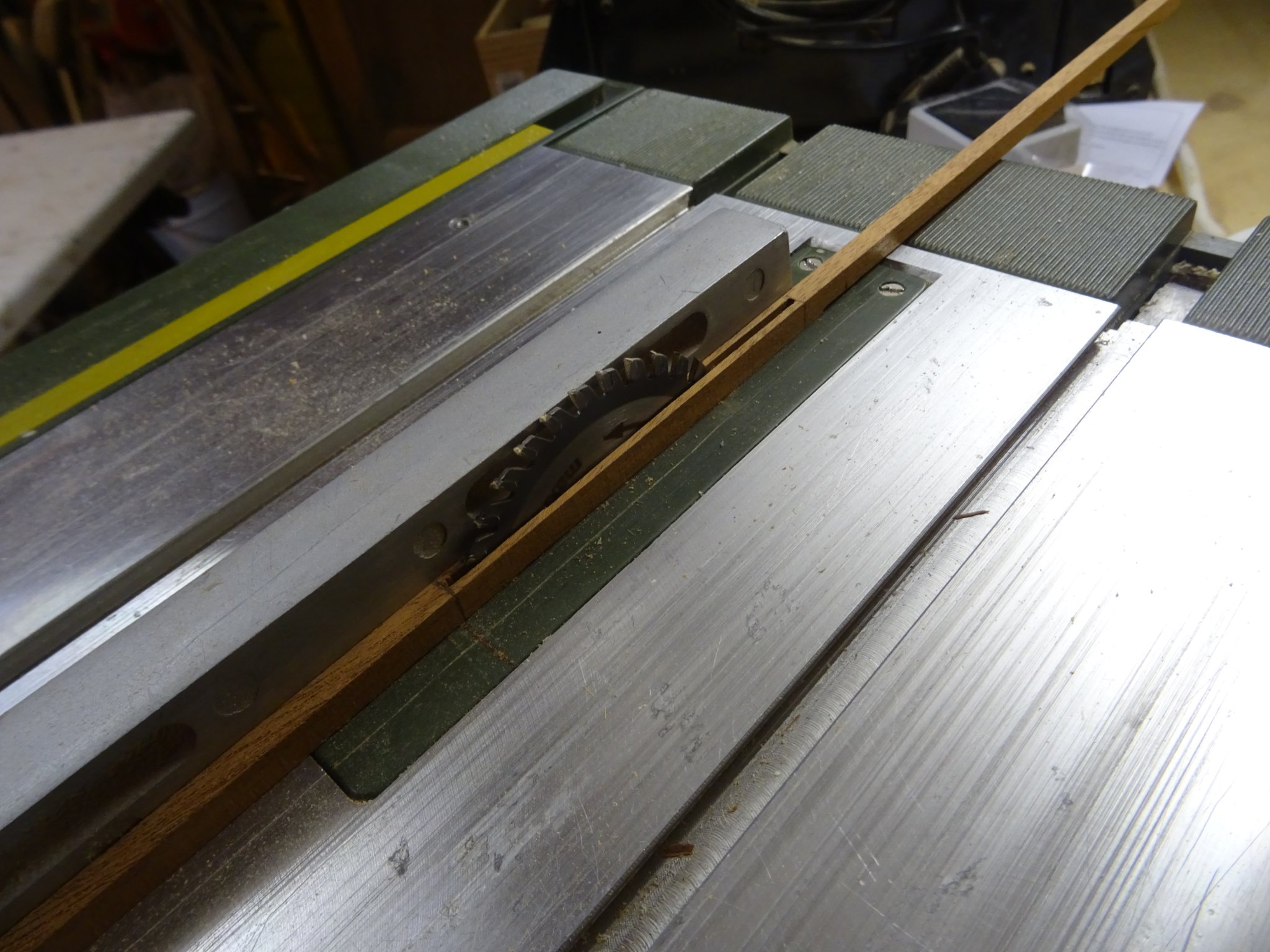
The keelson is made of ebony. To make the slot for the centre board I lay the keelson on the saw table with the saw blade fully turned down.
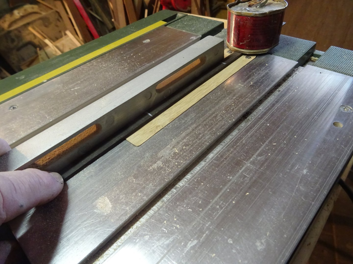
Then I turn up the running saw slowly until the desired length of slot is reached.
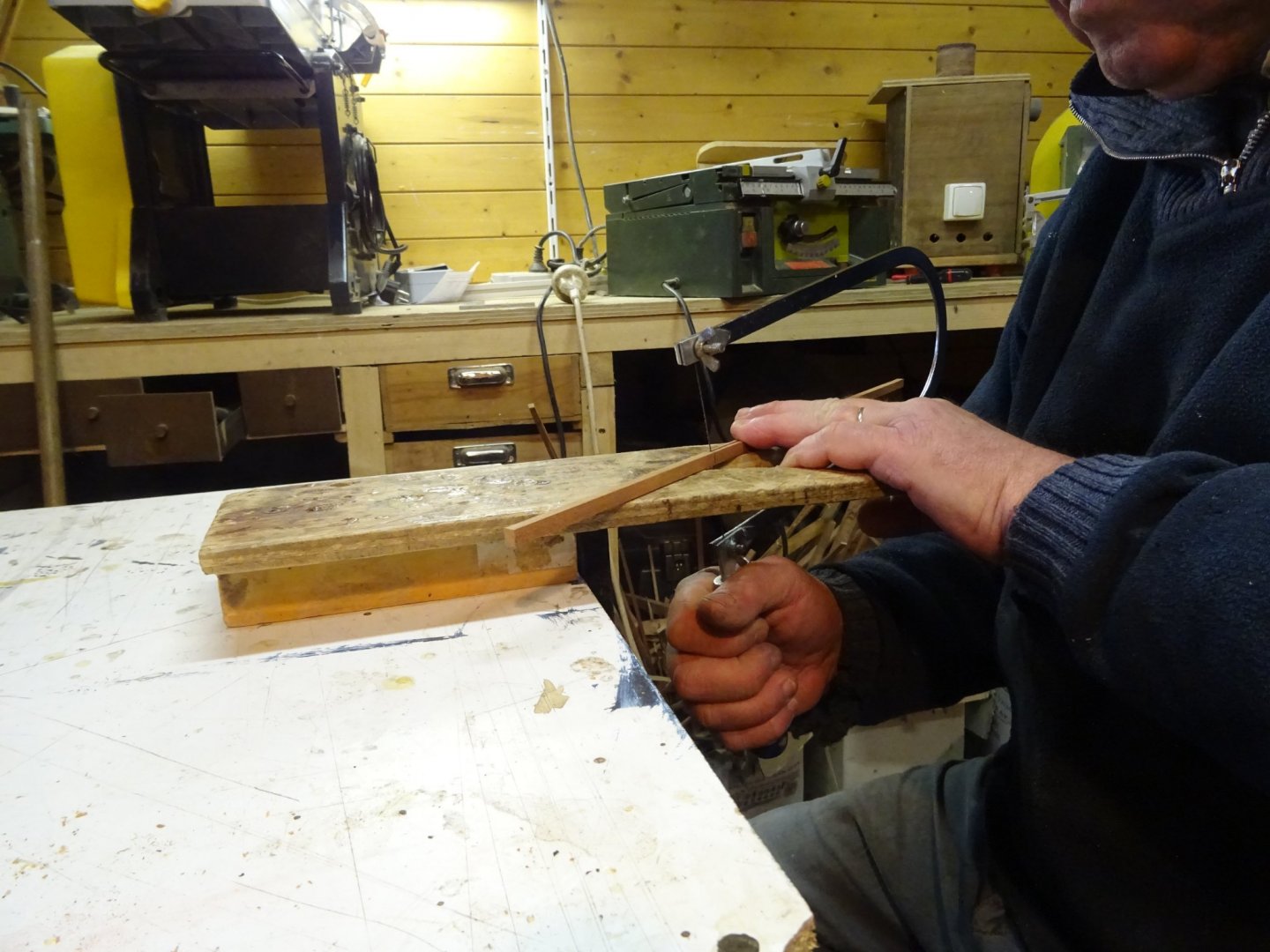
The ends of the slots still have to be cleaned up. I do it with the fret saw.
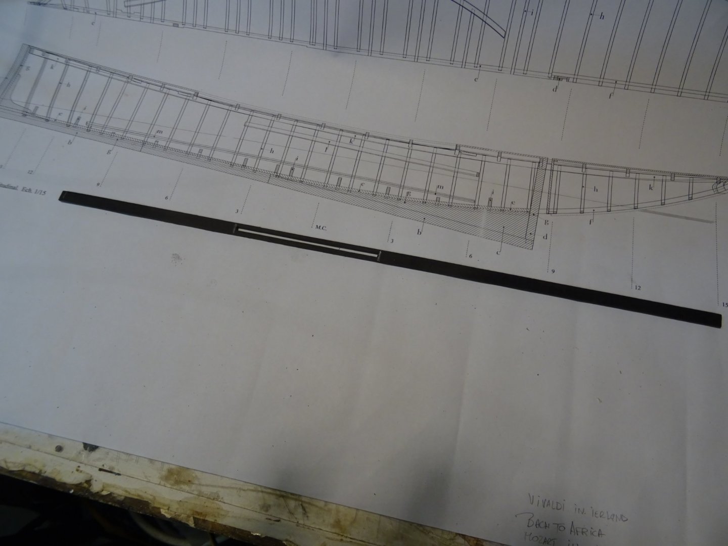
The keelson is ready to be placed
The keelson attached on the building board. The frames involved are removed in advance.

The keel is made of mahogany. The slot for the centre board is made as described above.

Cleaning up the ends of the centre board slot.
Gluing the dead wood.
fitting the keel on the keelson.

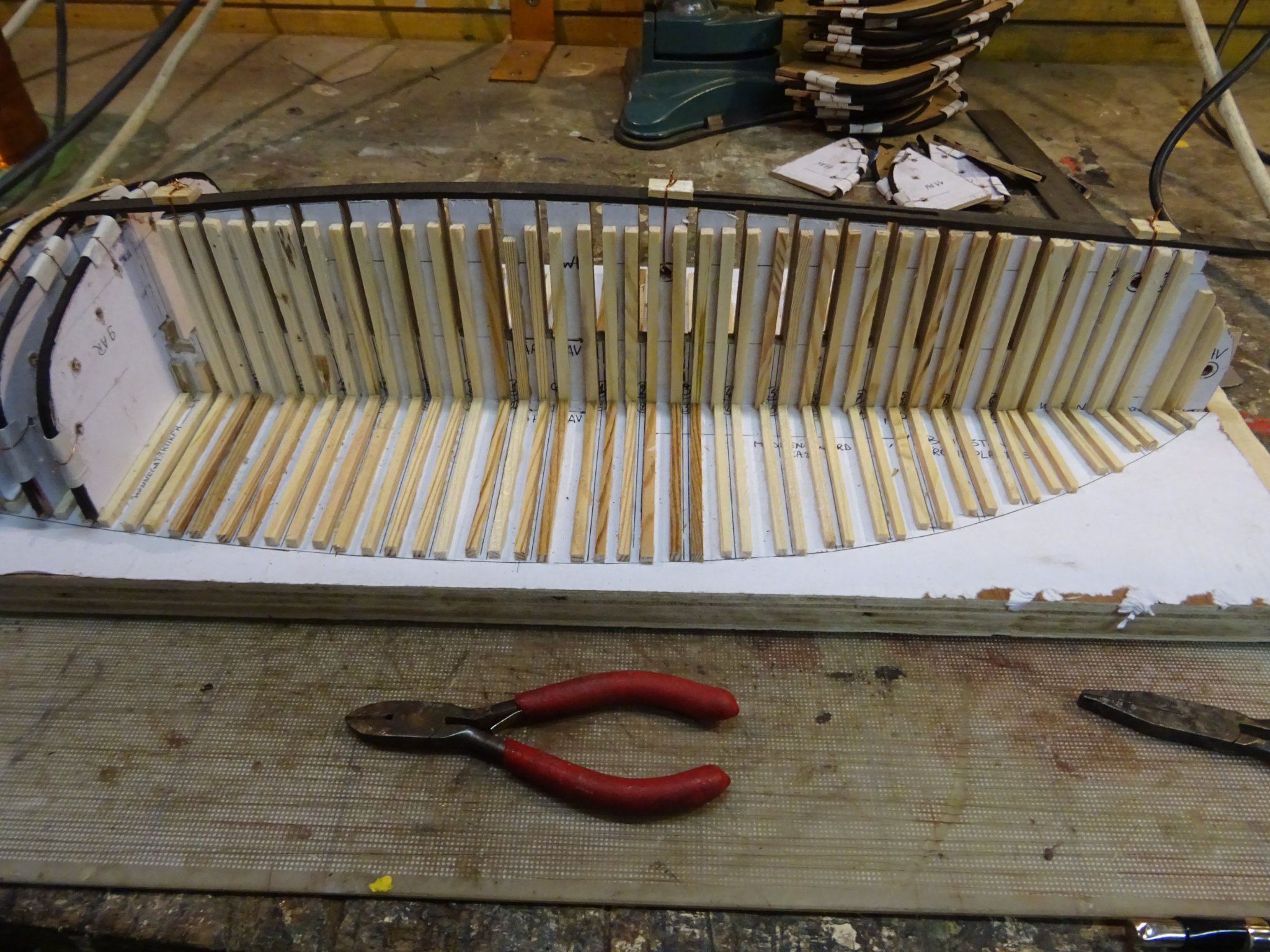
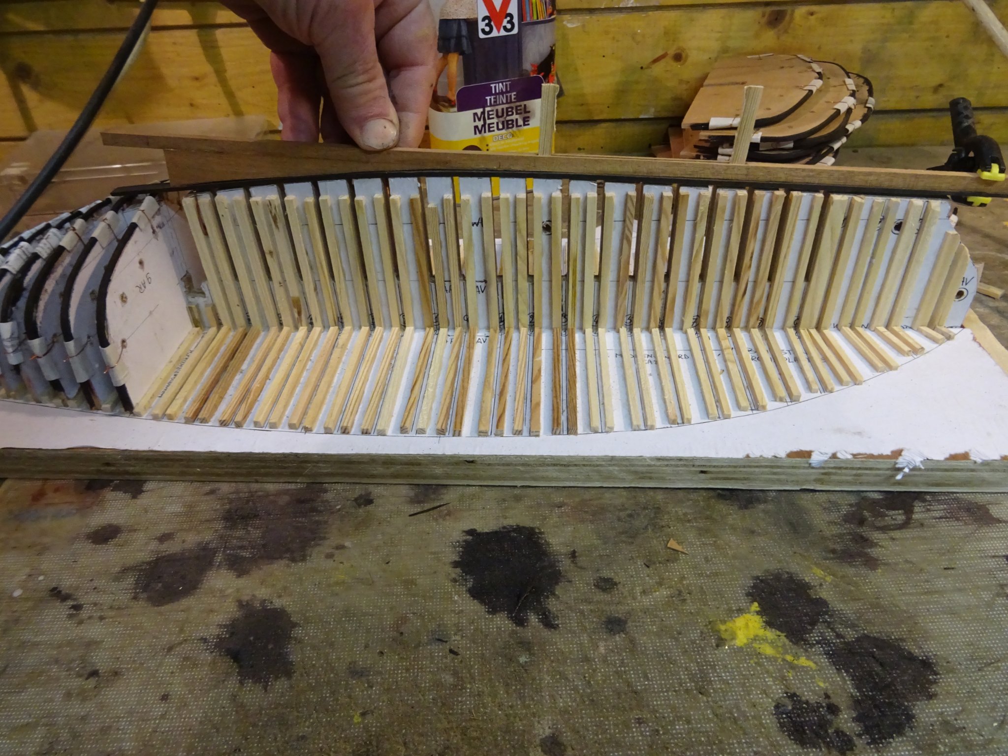
Getting ready to glue the frames on the kelson: the involved frames are removed from their templates. I label them to make the puzzle afterward easier.
I reattach now the frames on their templates and glue them on the keelson.
As the some frames now run over the slot of the centre board, the middle pieces have to be cut to give space for the keel.

The other frames go through the keel. Marking and sawing the slots for them.

Fitting the keel

When the rudderpost and the stem are glued on the keel, it can be glued into position.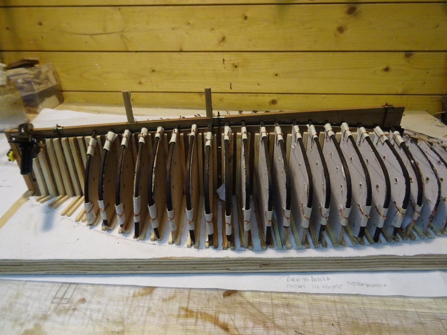
Thank you very much for reading this log, for your likes and for all your interesting reactions.
Till next week!
-
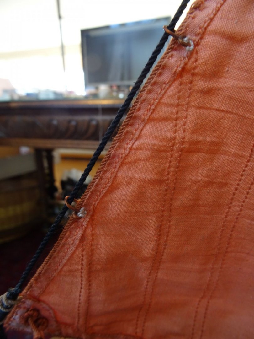
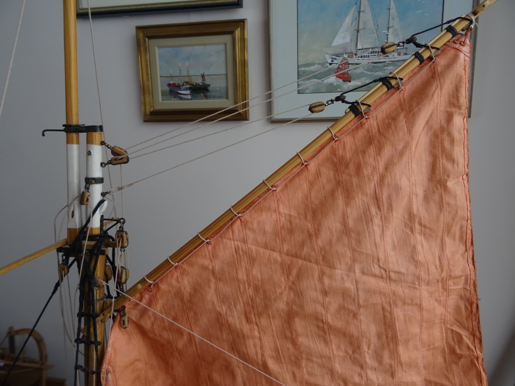
Rigging the top sail.
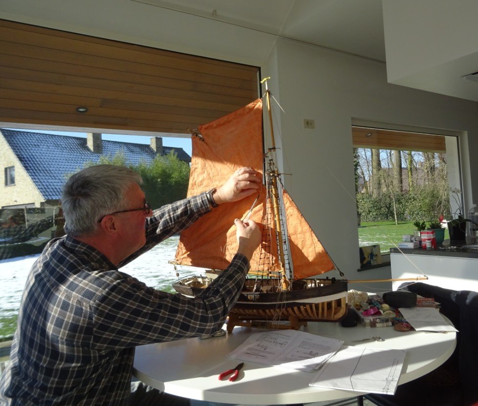
Attachment of the topsail to the gaff.
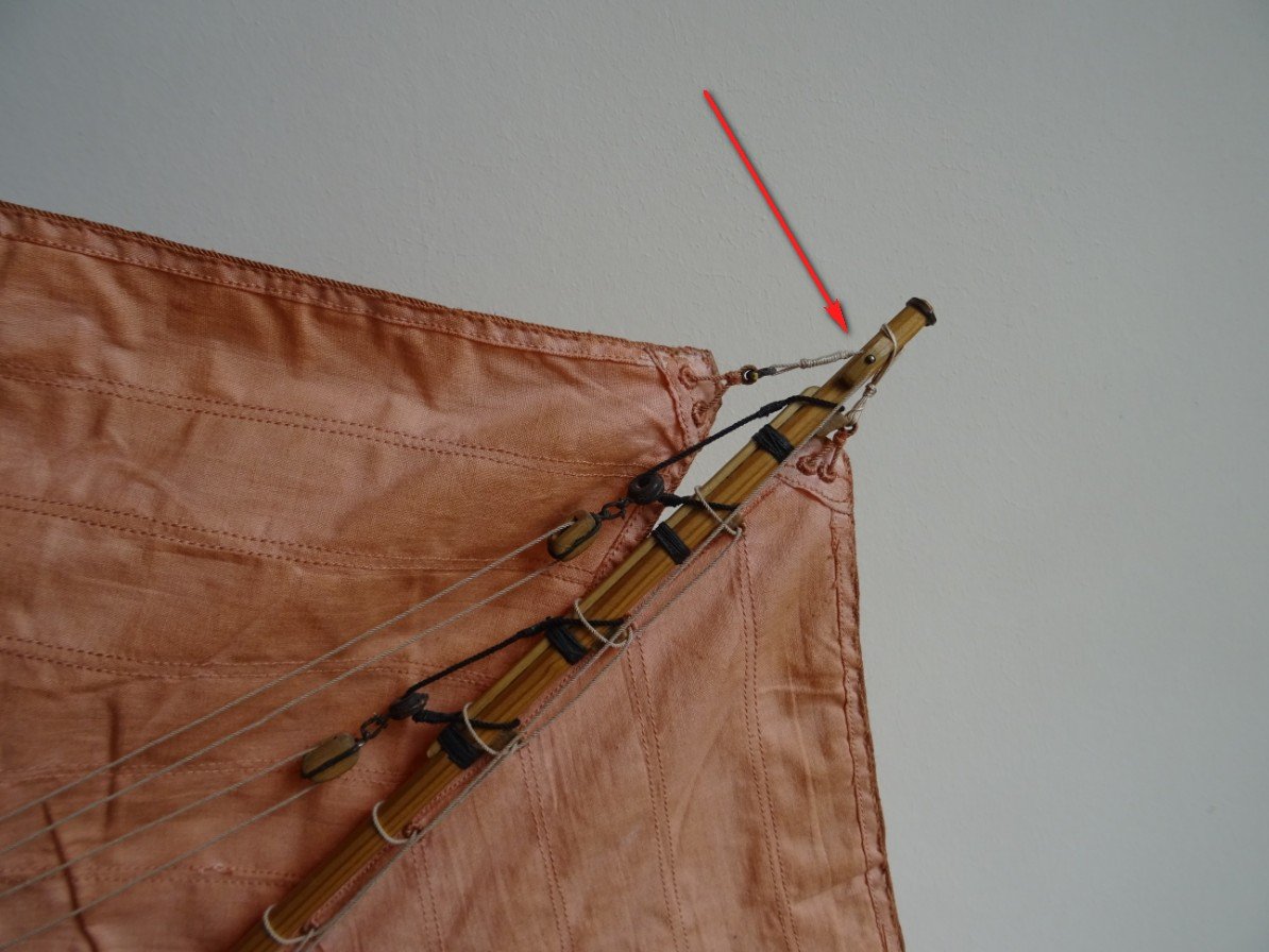
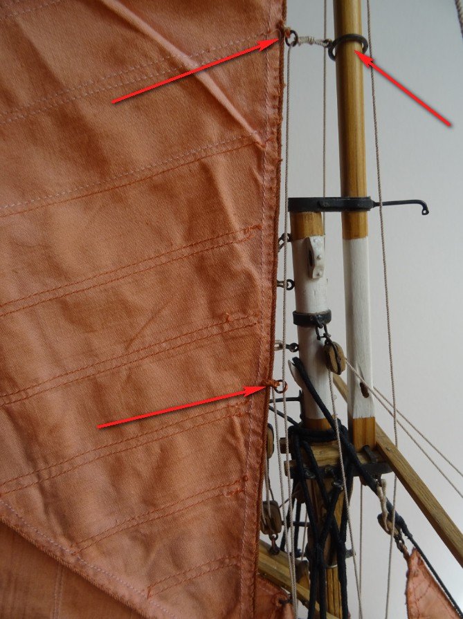
The topsail is held against the topgallant and mast by a rope that is attached to a traveler which can travel over the topgallant and that is going down through two rings at the forward leach of the top sail.
The top sail is hoisted.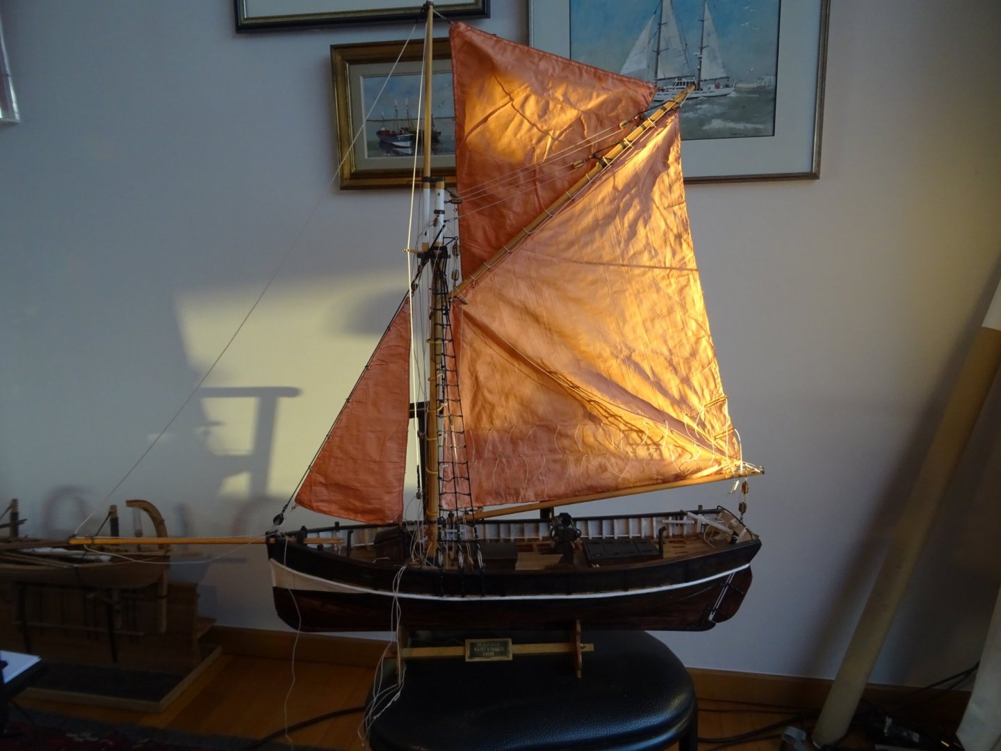
Thank you for reading this log, for your likes and for your constructive comments.
Till next week!
- tarbrush, Thukydides, mtaylor and 6 others
-
9
-
-
Whaw, just like the real one!
- FlyingFish and neilm
-
1
-
 1
1
-
-
-
Very interesting log, Hakan. I signed in to follow.
-
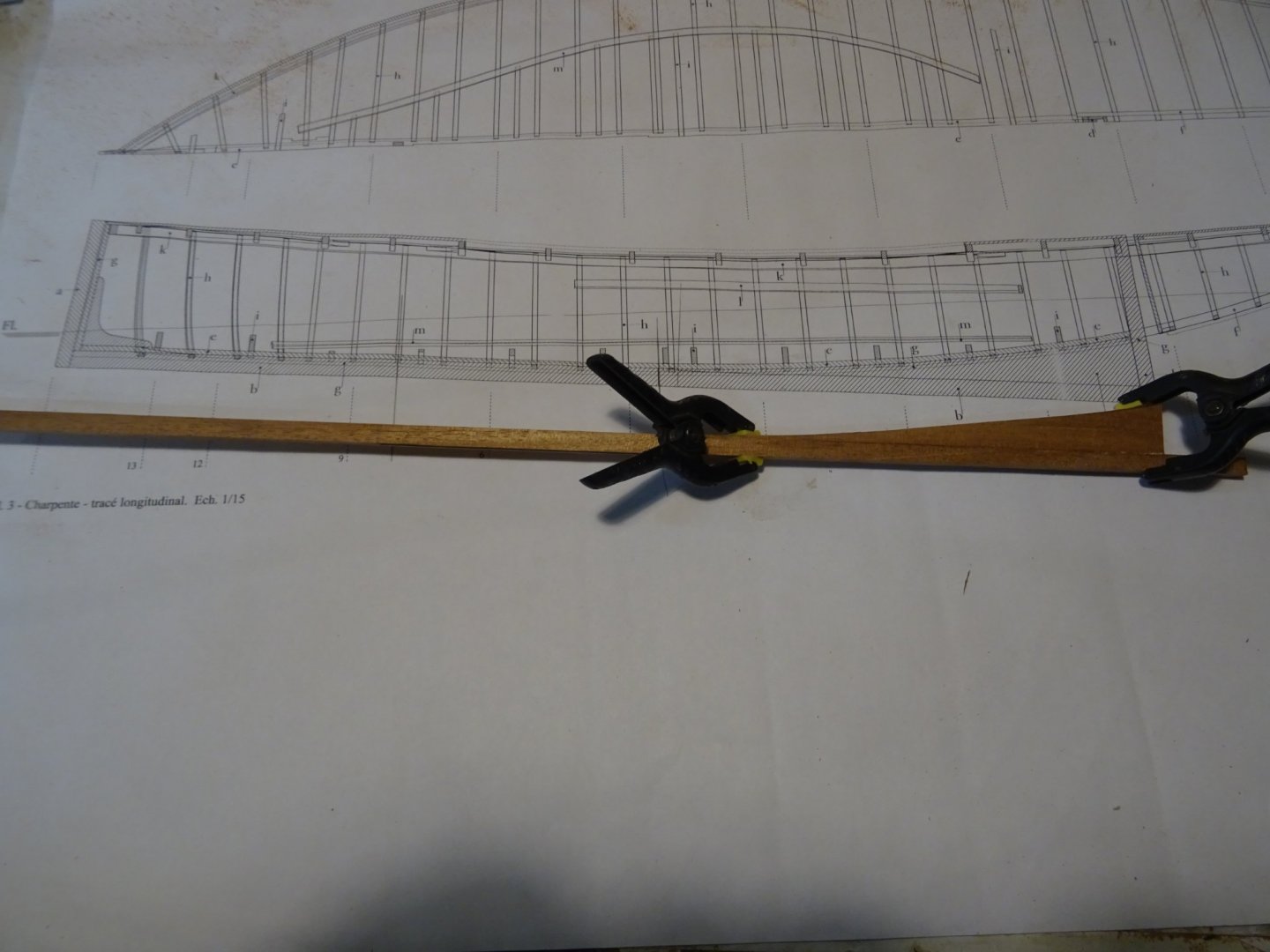
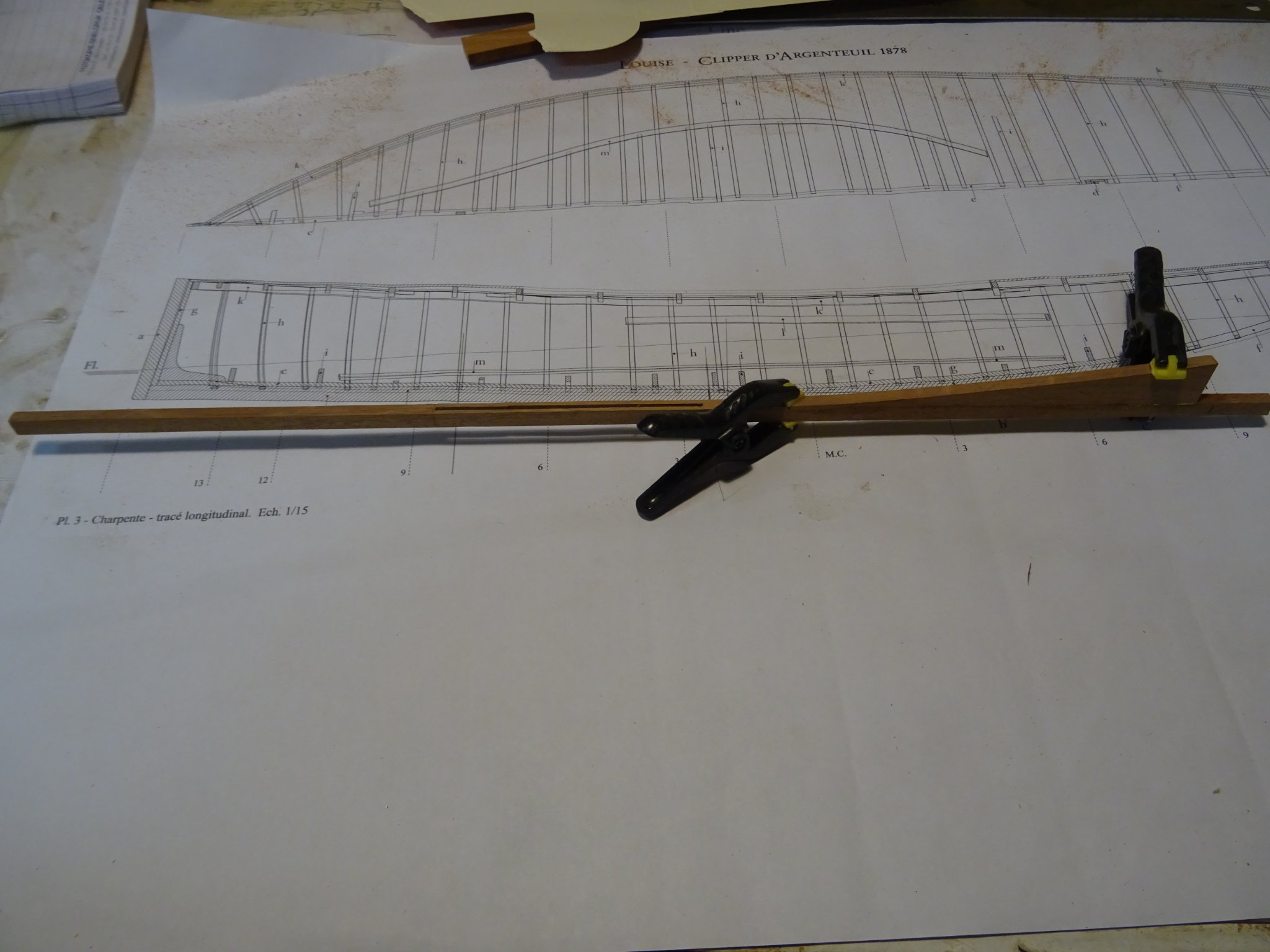
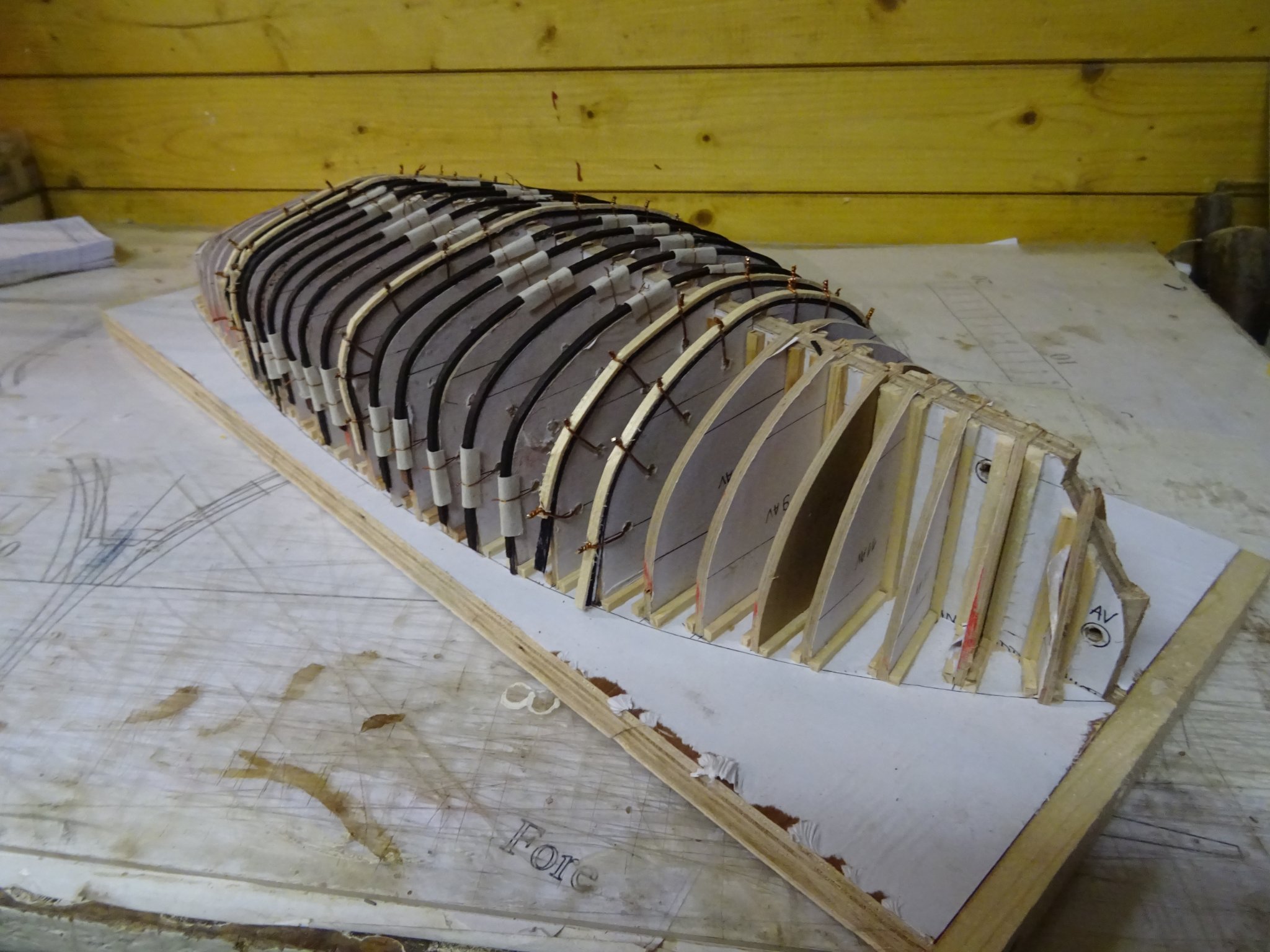
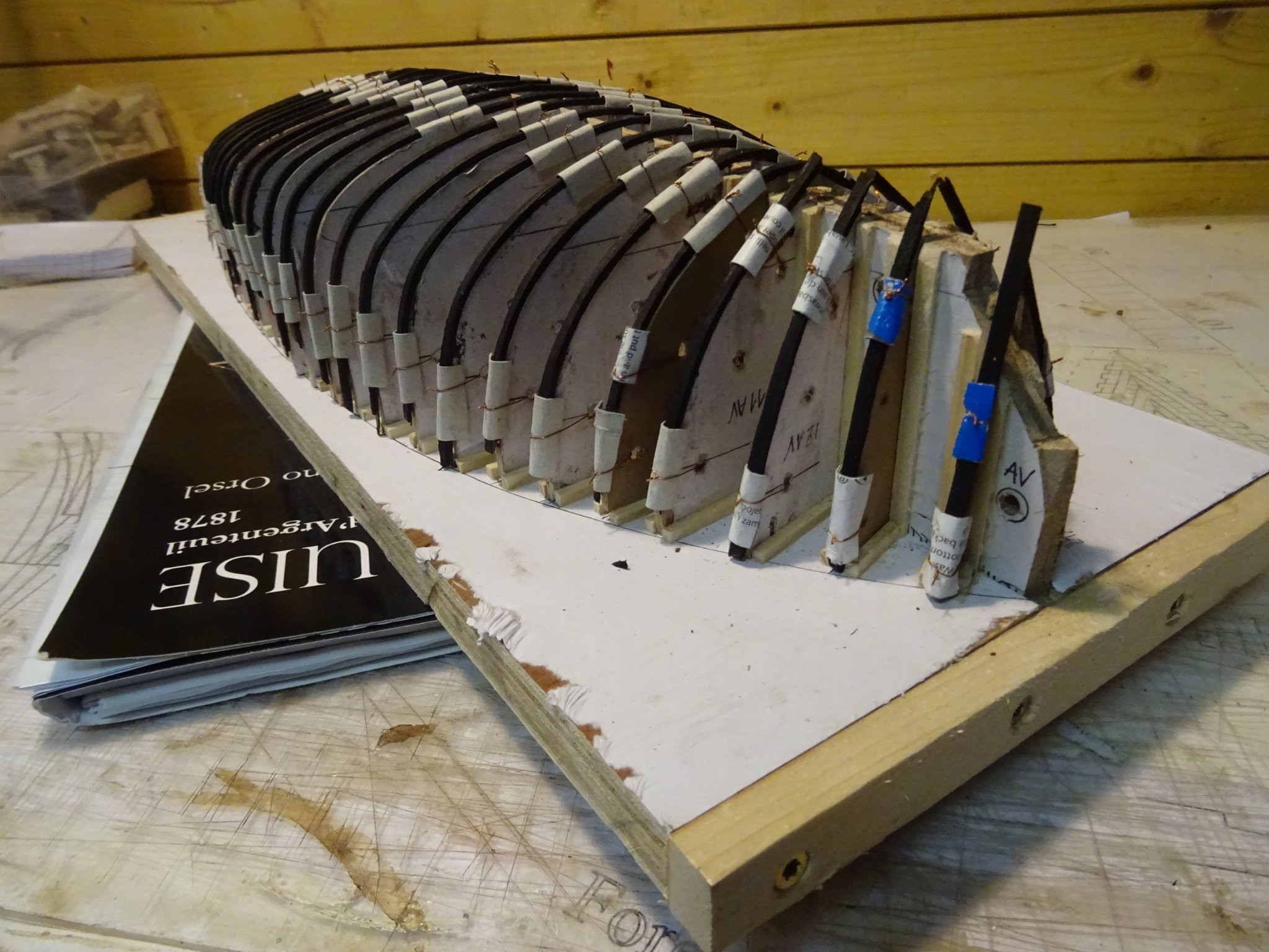
The closer I get to the bow and the stern, the greater becomes the slope of the frames. To my pleasant surprise, I can bend the veneer strips nicely along the template without breaking them. This probably wouldn't have been possible with the stiffer ebony.


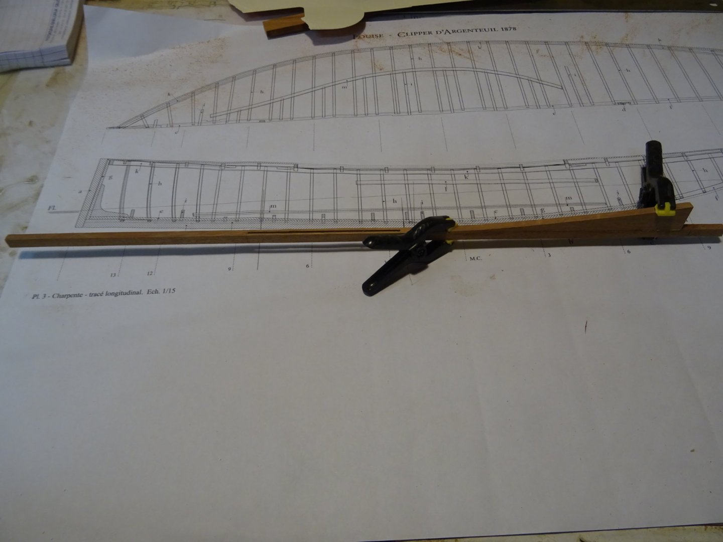
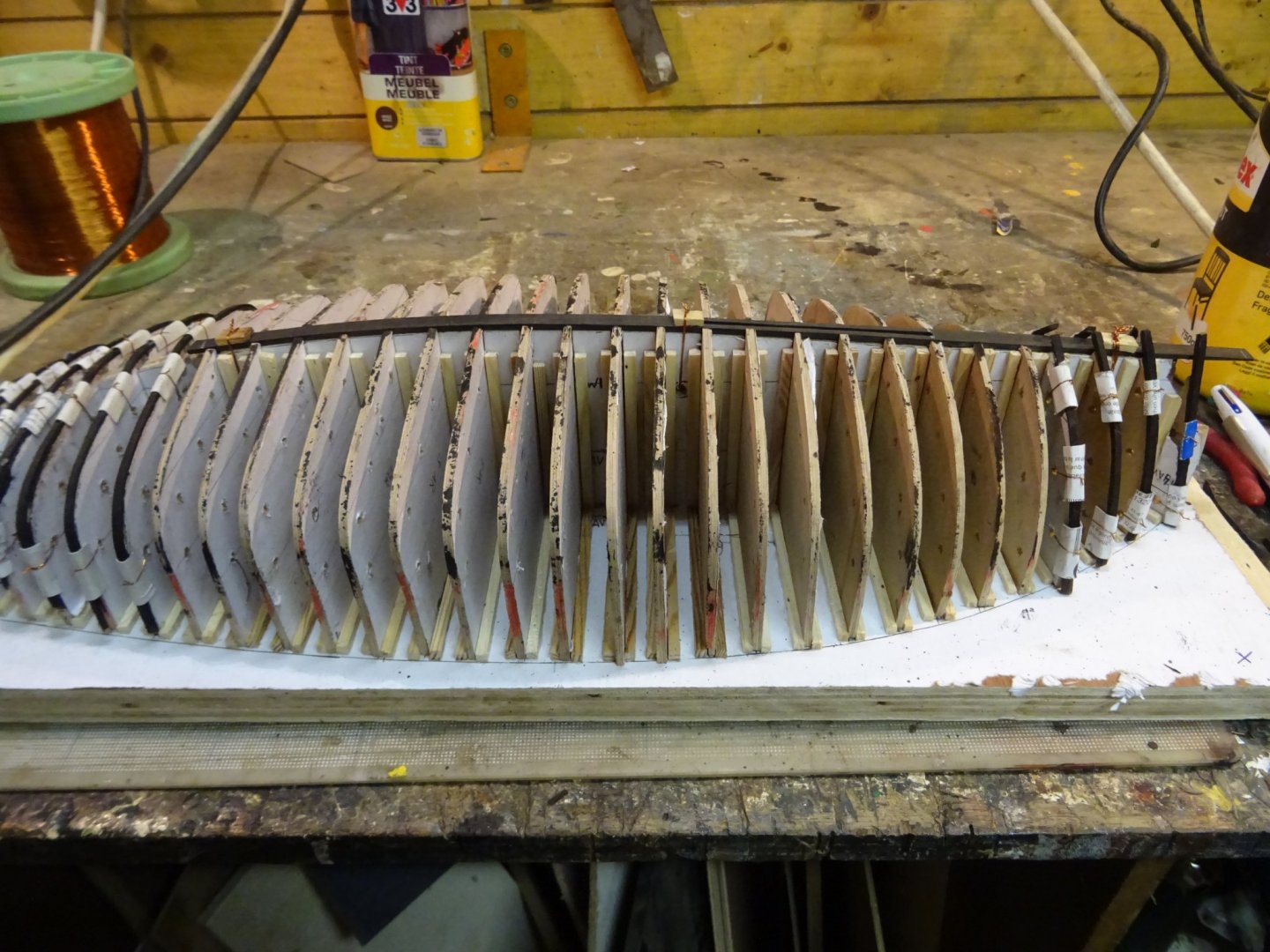
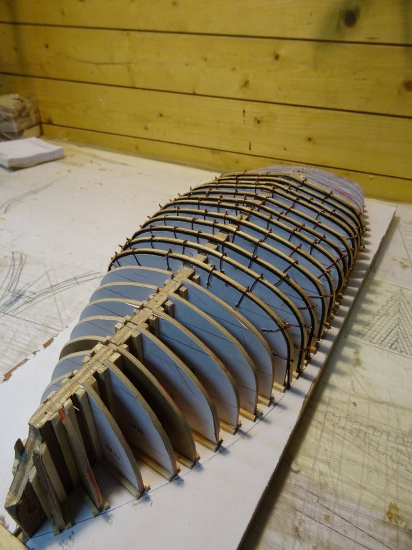
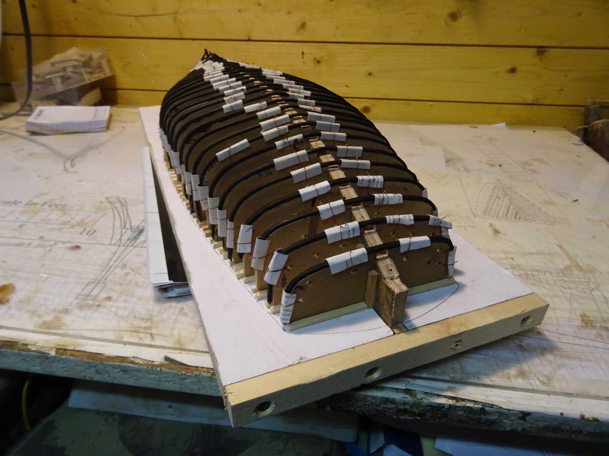
The frame production continues steadily.

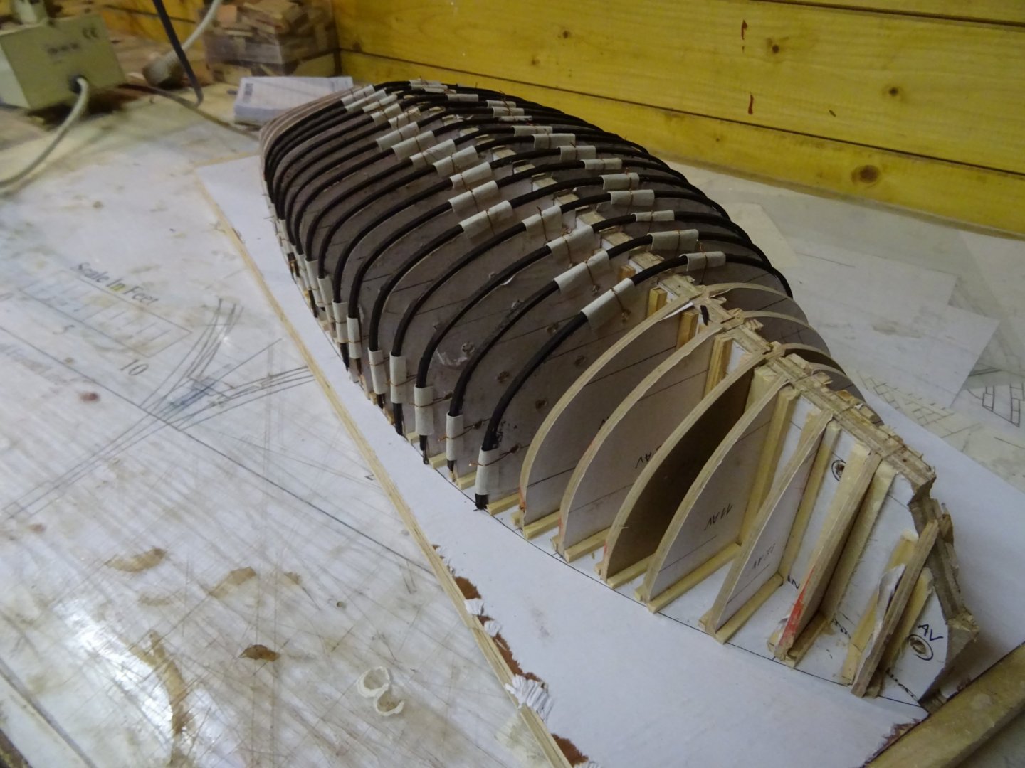
This week all frames are made.

Thank you very much for reading this log, for your likes and for all your interesting reactions.
Till next week!
-
-
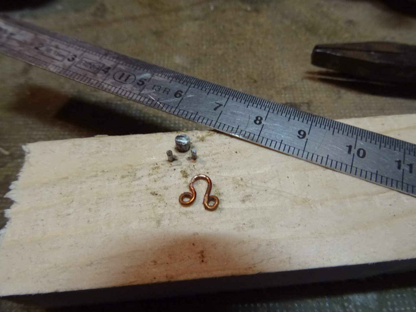
The fore sail is attached to the fore stay with hanks. Making the hanks.

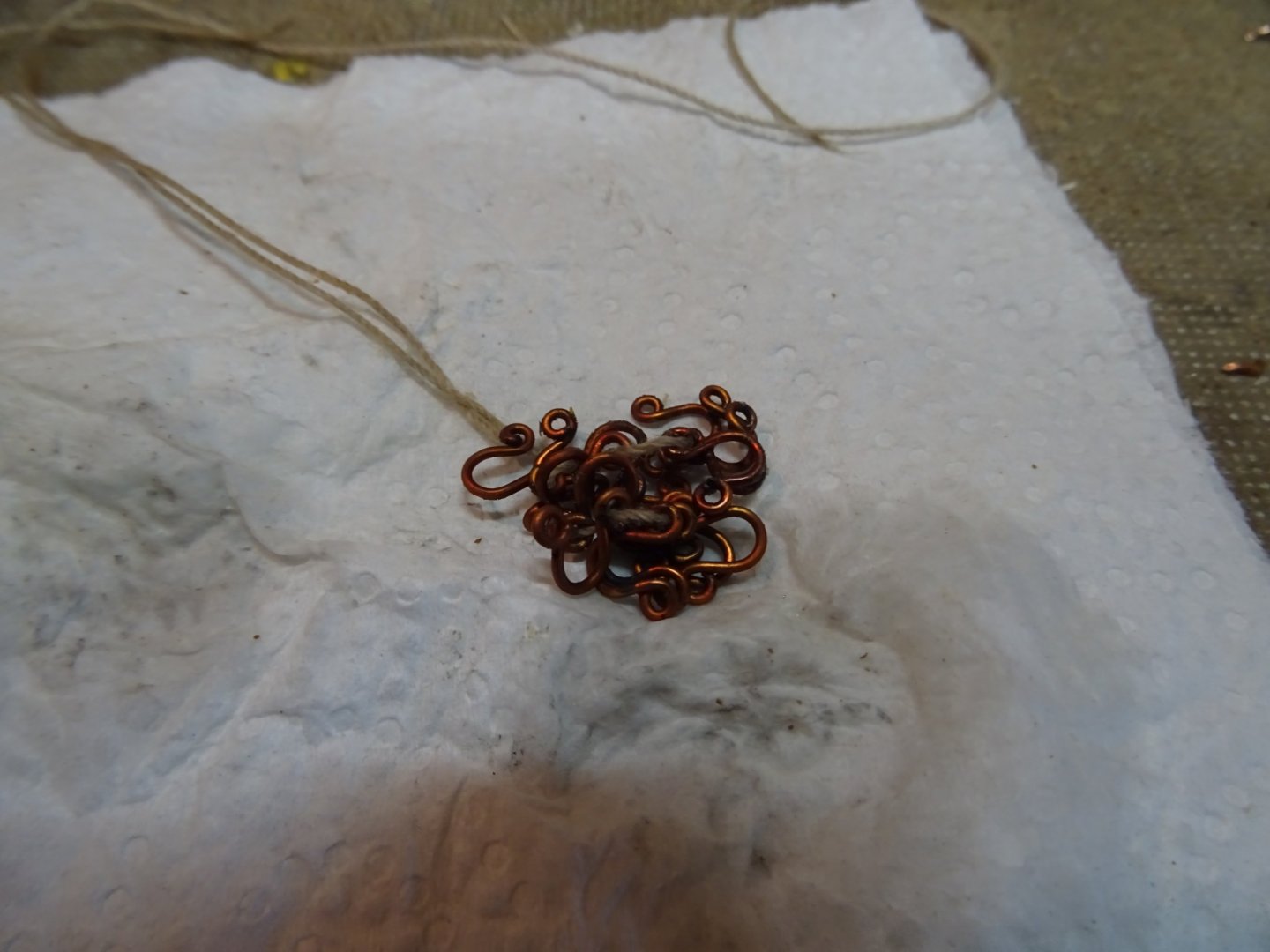
Sewing the hanks to the sail and the forestay.
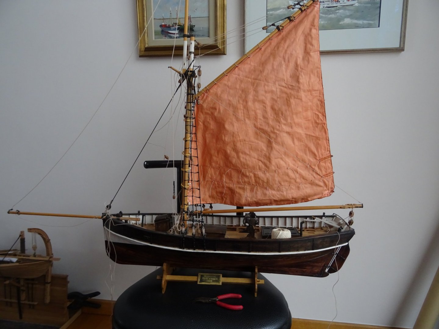
Rigging sails is serious business.
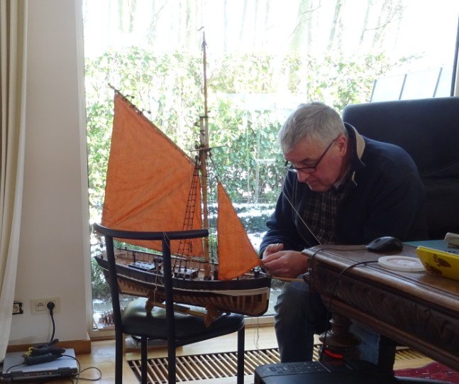
The shrimper with main sail and fore sail. Two more sails to go.
Thank you for reading this log, for your likes and for your constructive comments.
Till next week!
- Roger Pellett, Baker, Geowolf and 6 others
-
9
-
-
-
On 4/3/2021 at 12:12 PM, wefalck said:
Be cautious when working with ebony. It seems that ebony dust is not very healthy ...
Thank you for the advice, Eberhard, I was not aware of that.
- Mirabell61 and mtaylor
-
2
-
-
-
2. Making of the frames
Before making the frames, something about the wood. Mr Bruno Orsel states that mahogany for old models is often associated with pleasure craft. He recommends to use mahogany for the exterior and ebony for the interior, included the frames, and indeed his model is a real beauty.
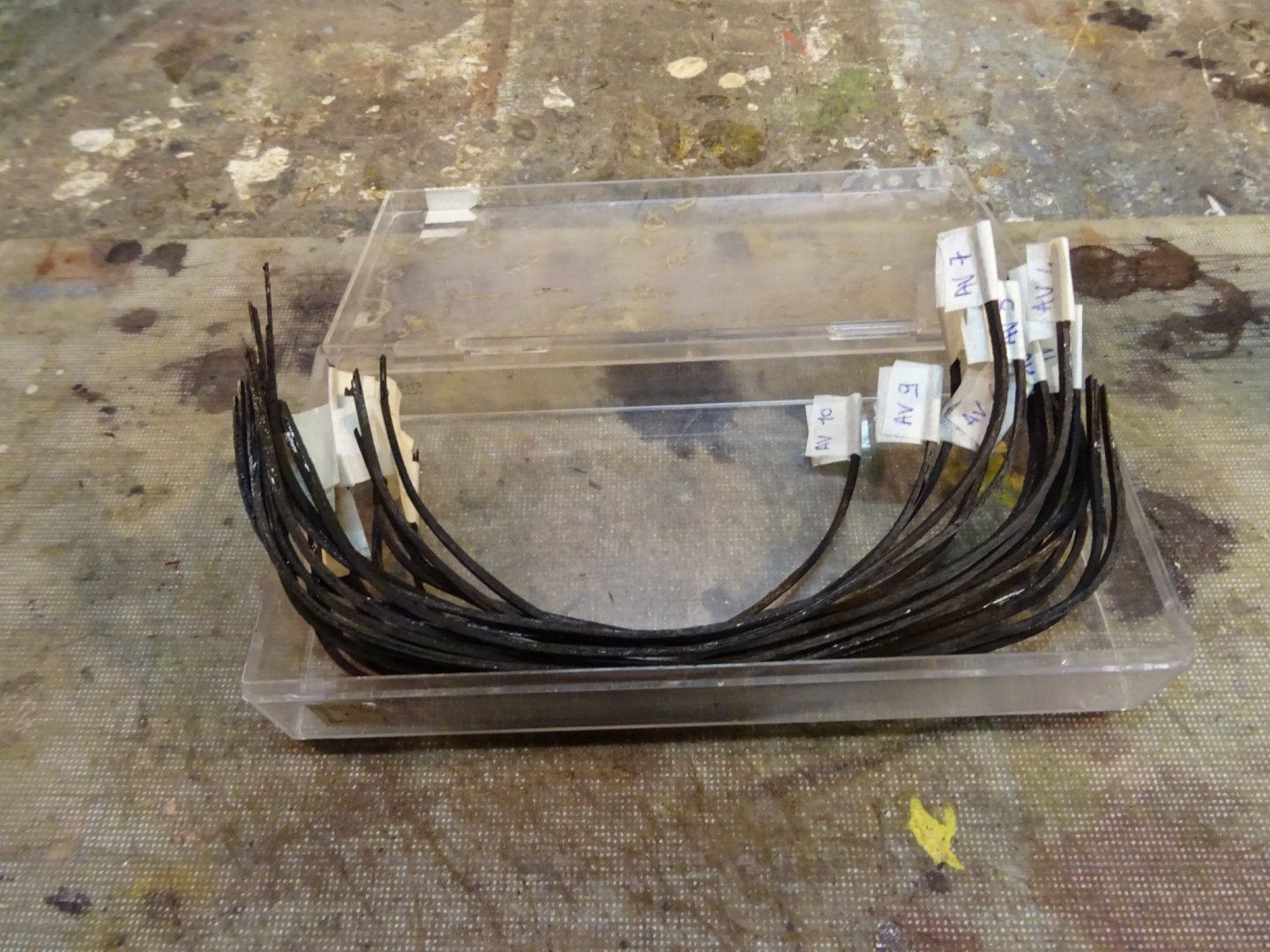
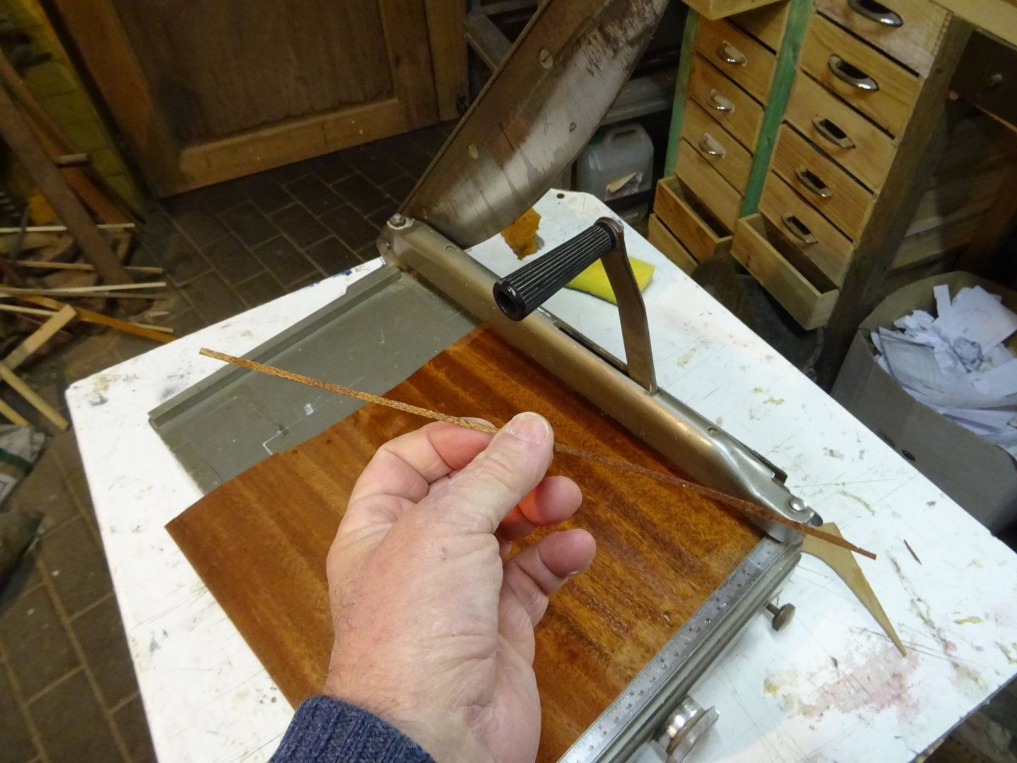
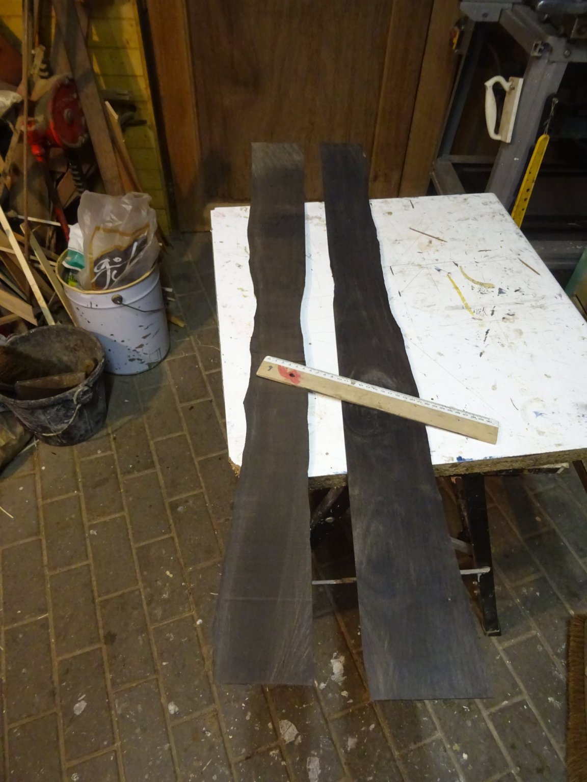
The frames are laminated with ebony veneer, thickness 0.6 mm. To find the necessary mahogany was not a problem. Ebony beams are more difficult to find but also available. Ebony veneer on the other hand is another story. The only ebony veneer that I could find (picture below) has an average thickness of three mm, not really veneer, but rather planks.

They cost also about 50€/500 grams. That means that you see about 100€ wood above. I will not plane those planks from 3mm to 0.6mm, that would be a waste. They will be used for making more structural parts. But I also need black 0.6mm veneer. I have 0.6mm mahogany veneer and decide to use that for making the frames.
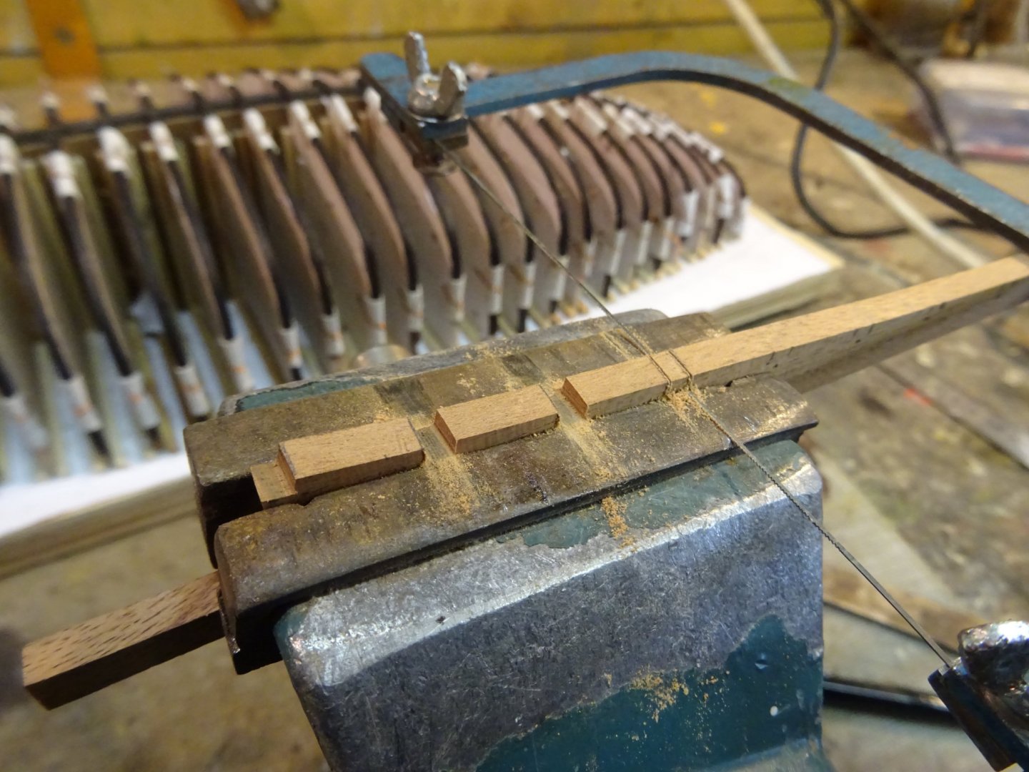
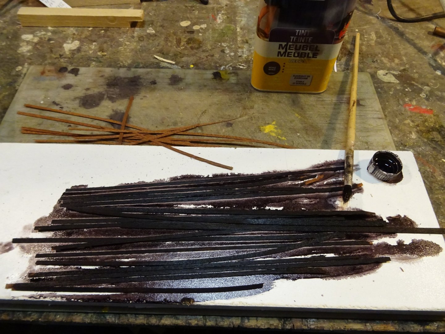
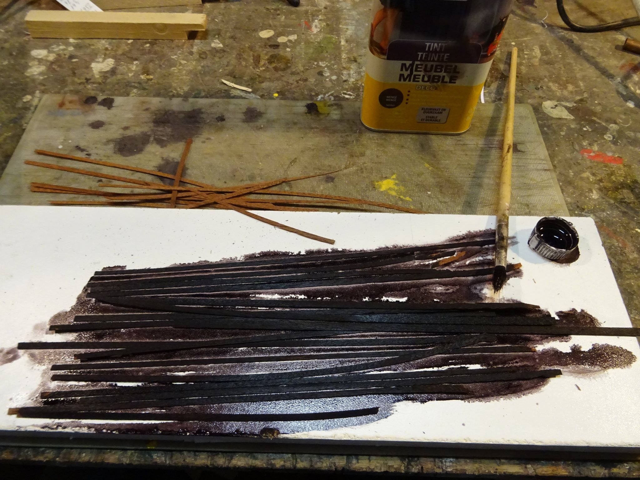
I start with cutting an amount of mahogany veneer strips with a paper cutter ...
... and stain them black (color: wenge).
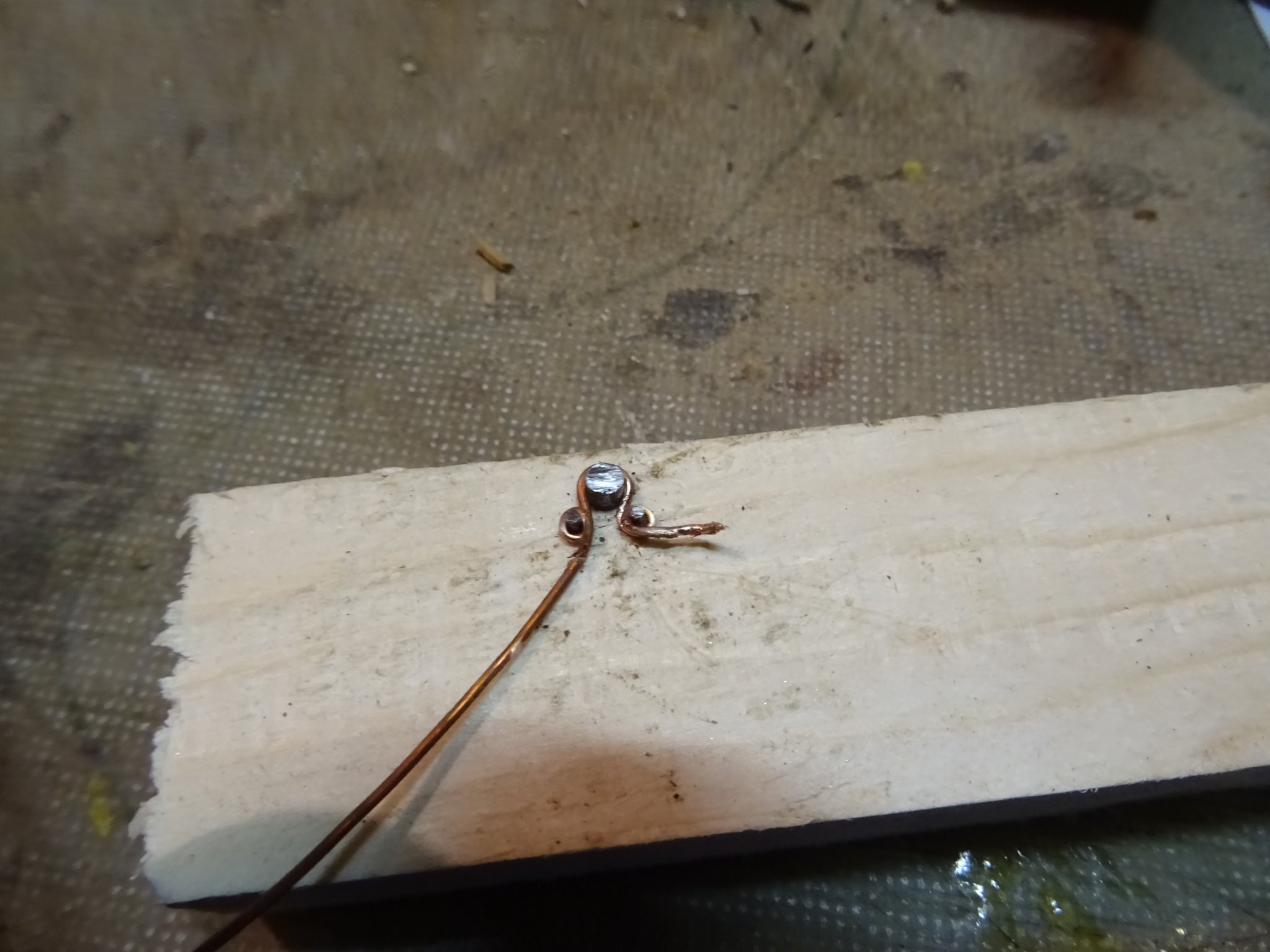
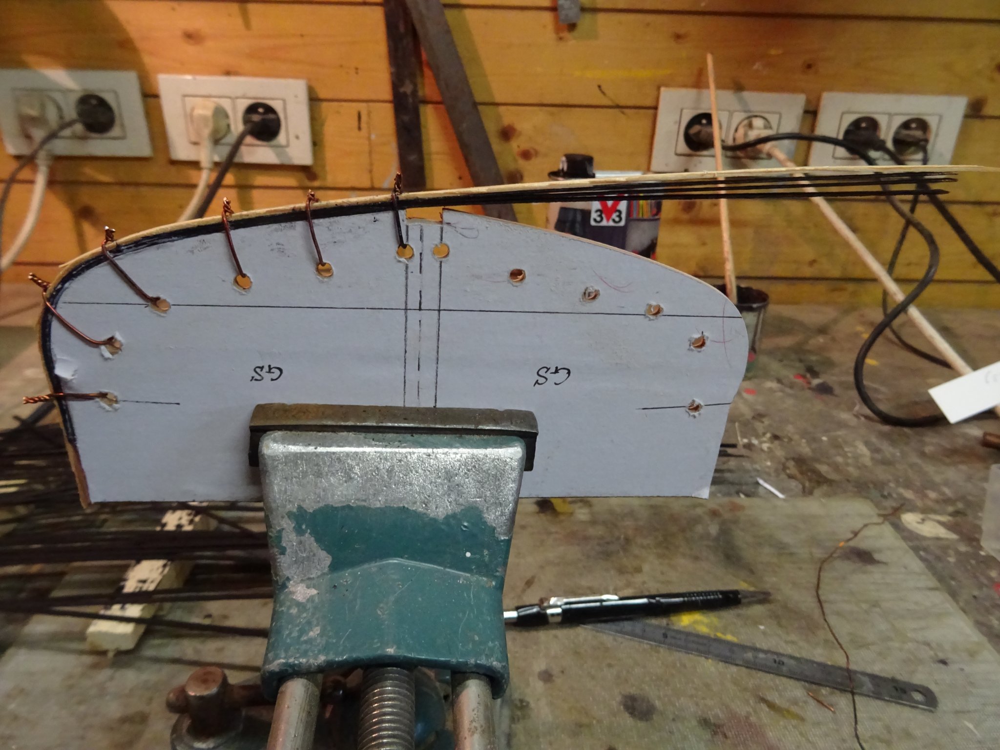
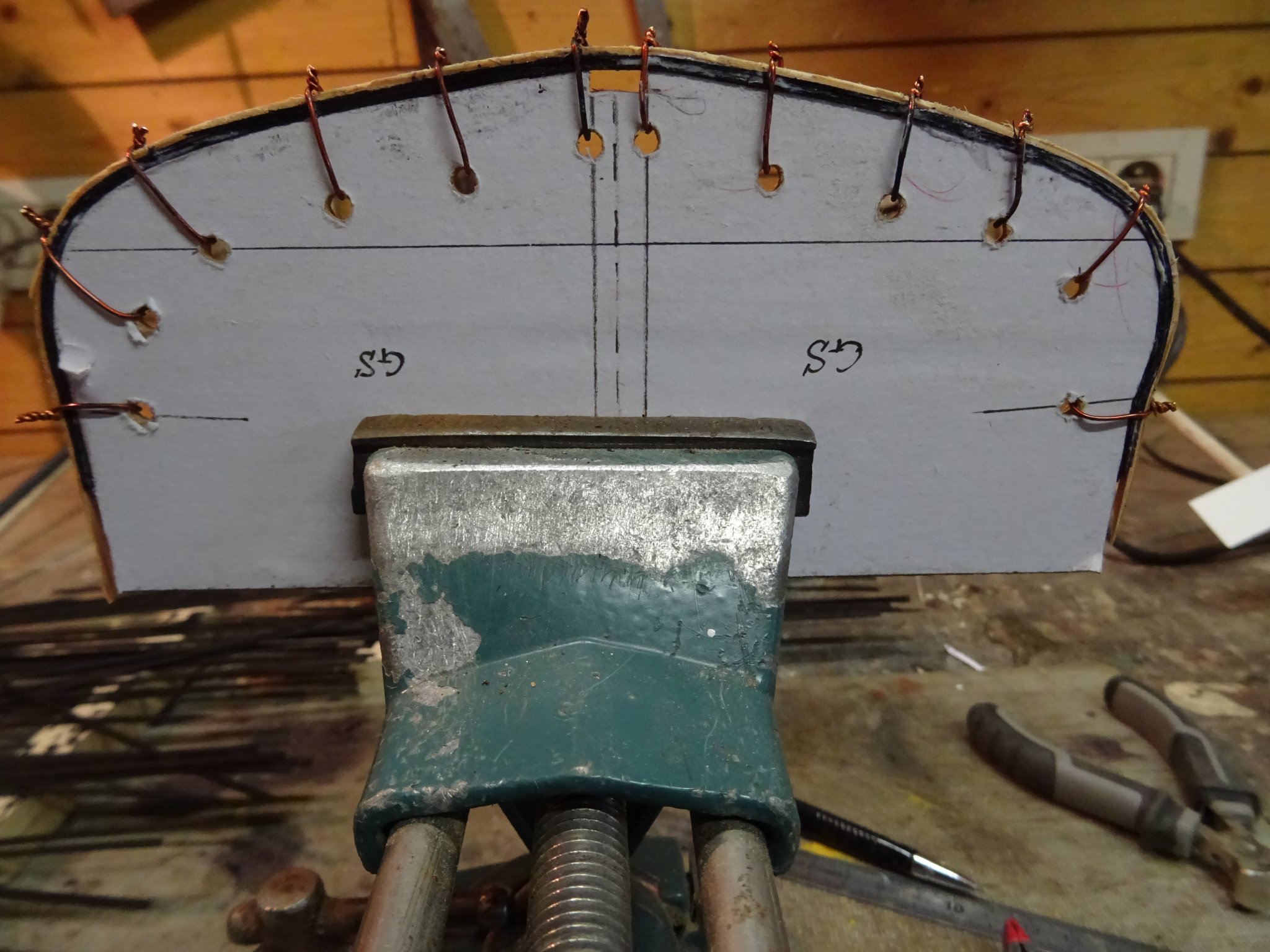
To make the laminating easier, I drill holes around the templates.
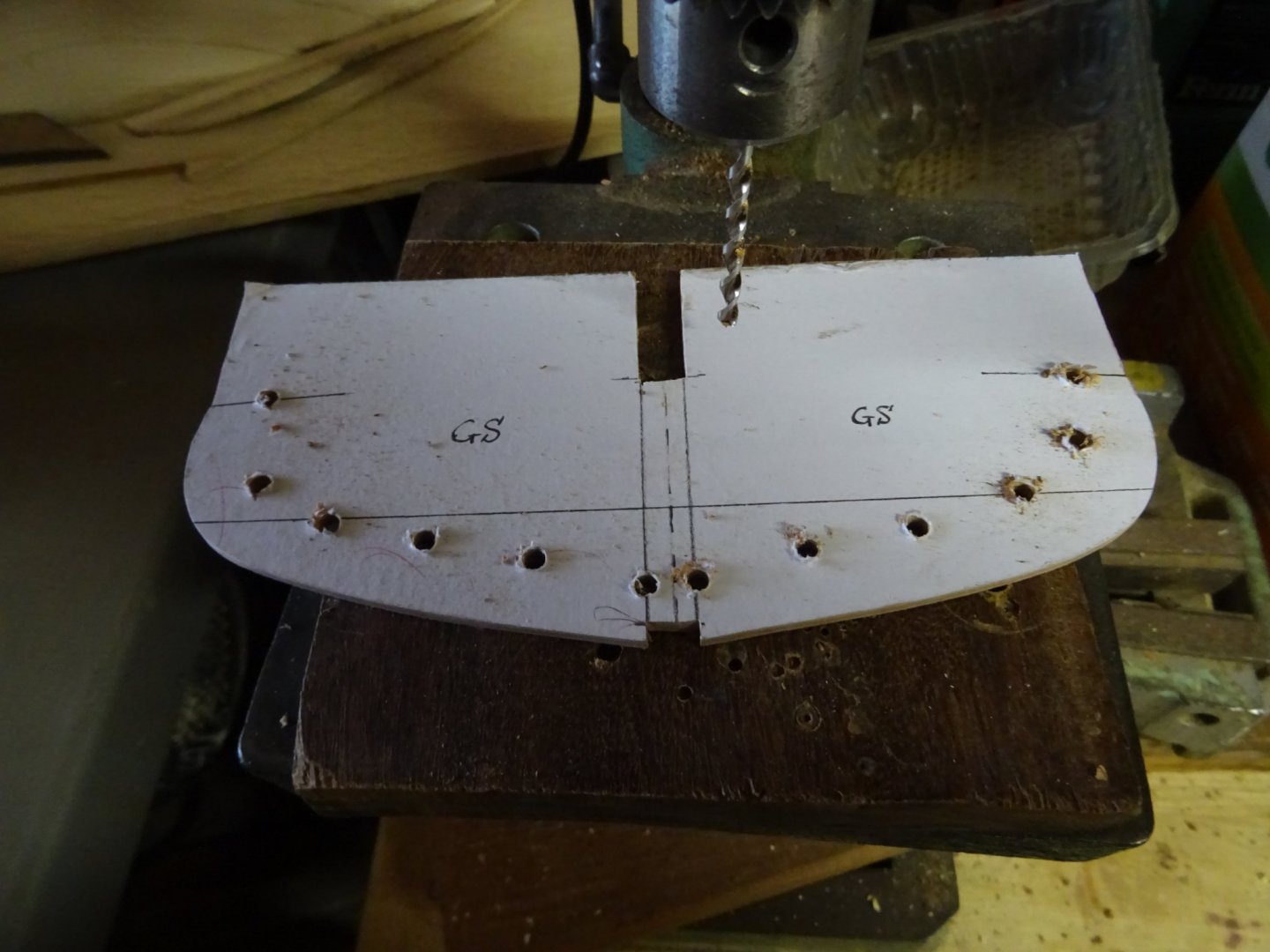
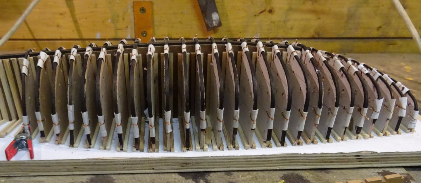
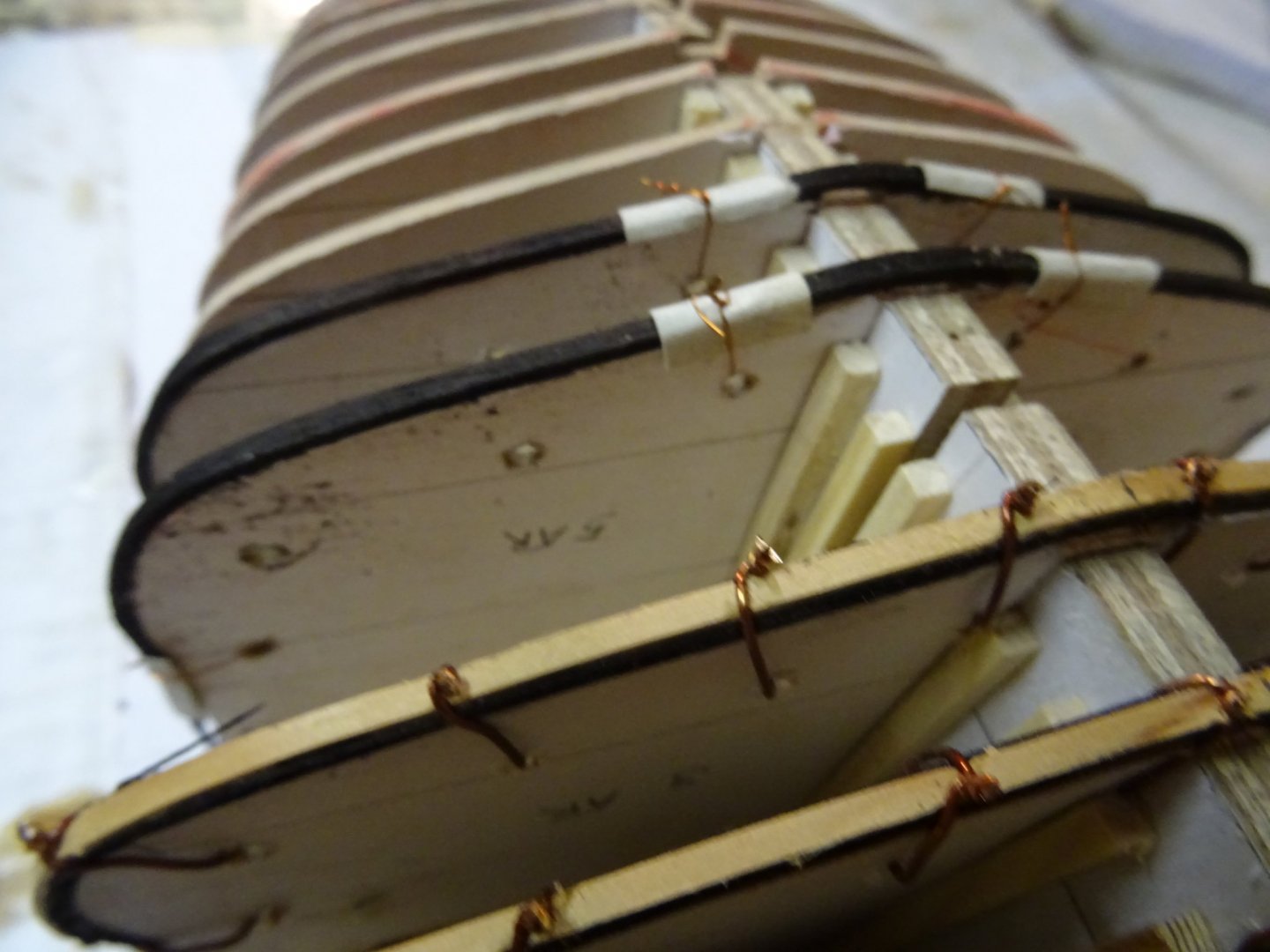
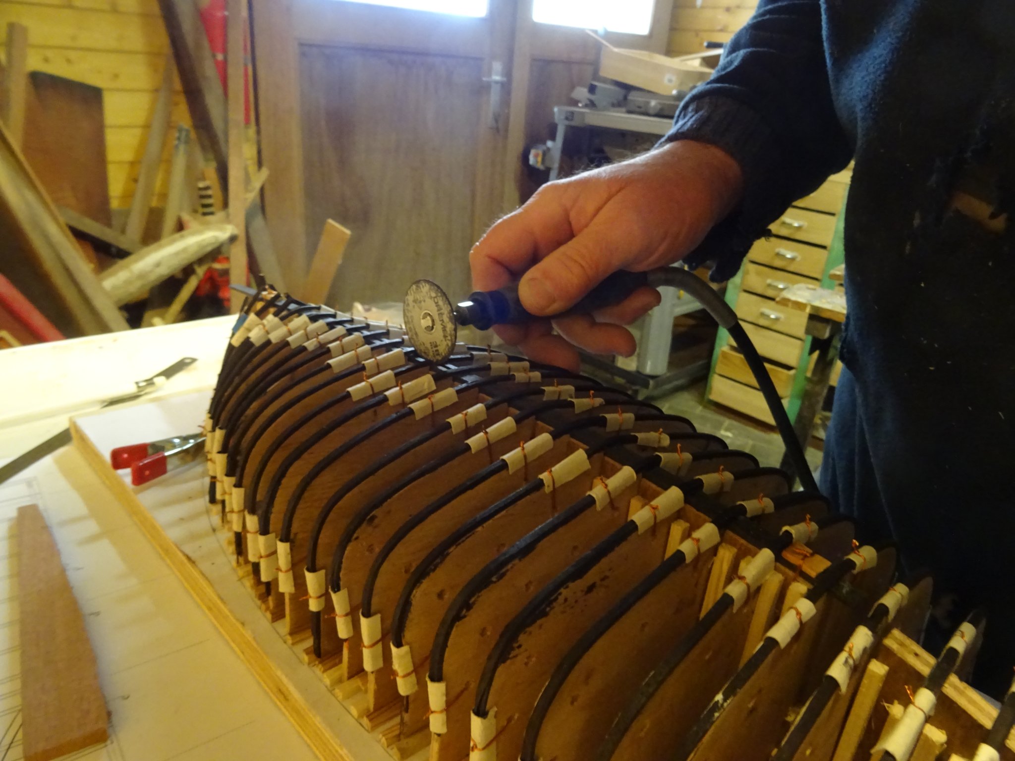
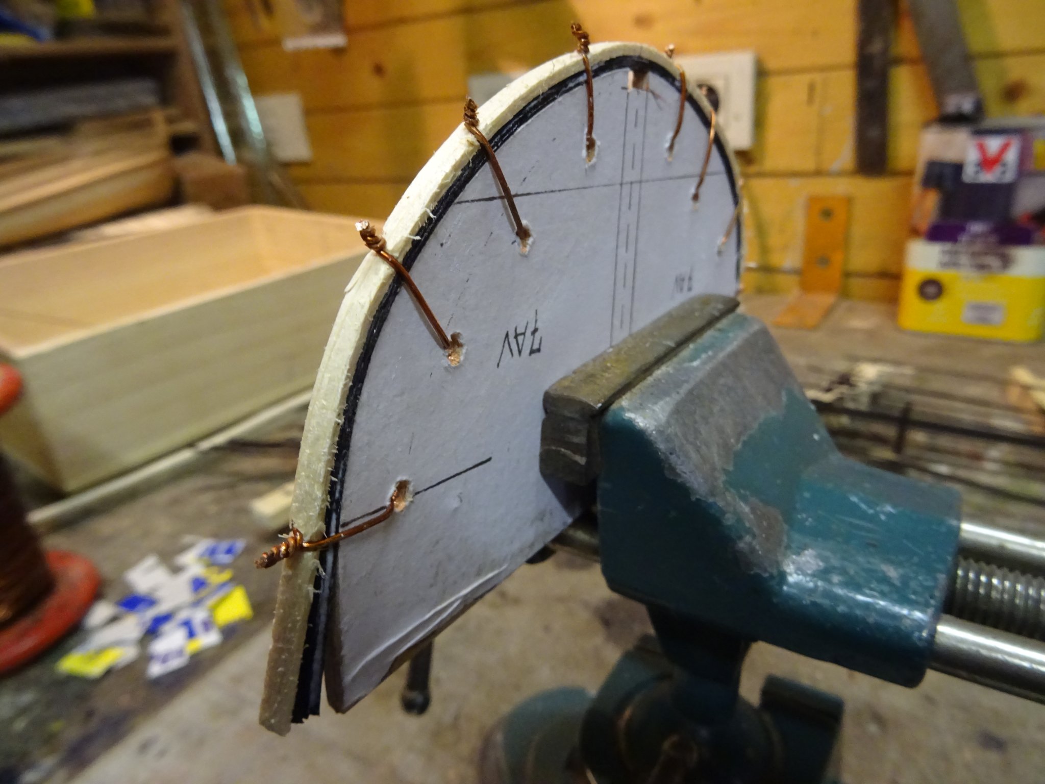
The frames are built up from three veneer strips which are glued together round the template. I fix them with wire. On top of the frame I lay a thin wooden strip to prevent the cracking of my veneer strips when bending them around the template and also to protect them from being damaged by tightening the wire.


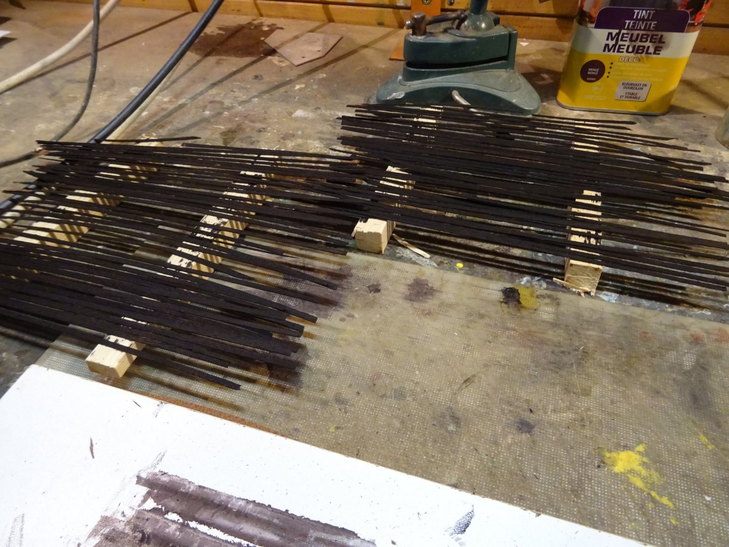
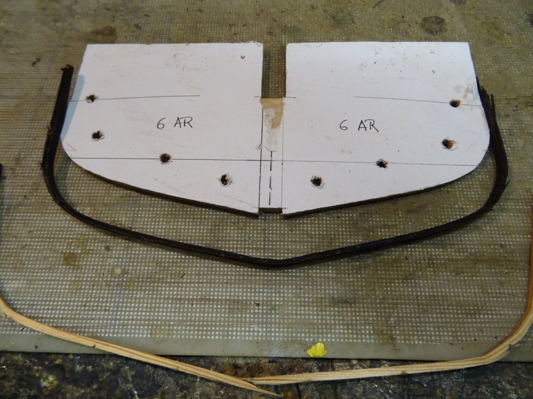
I place them on the building board to dry.
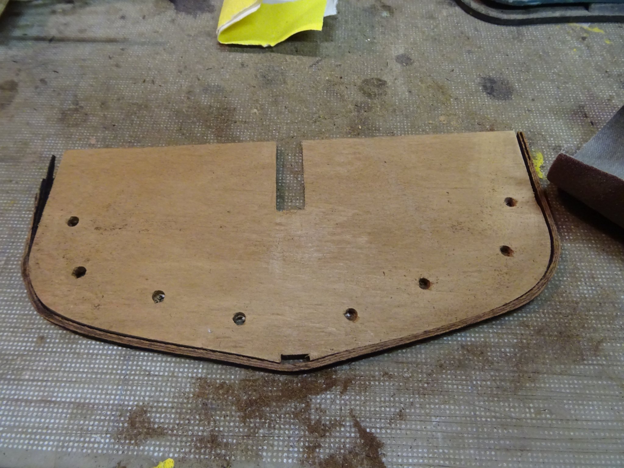
Next day I can remove the laminated frame from the template. It nicely keeps its shape.

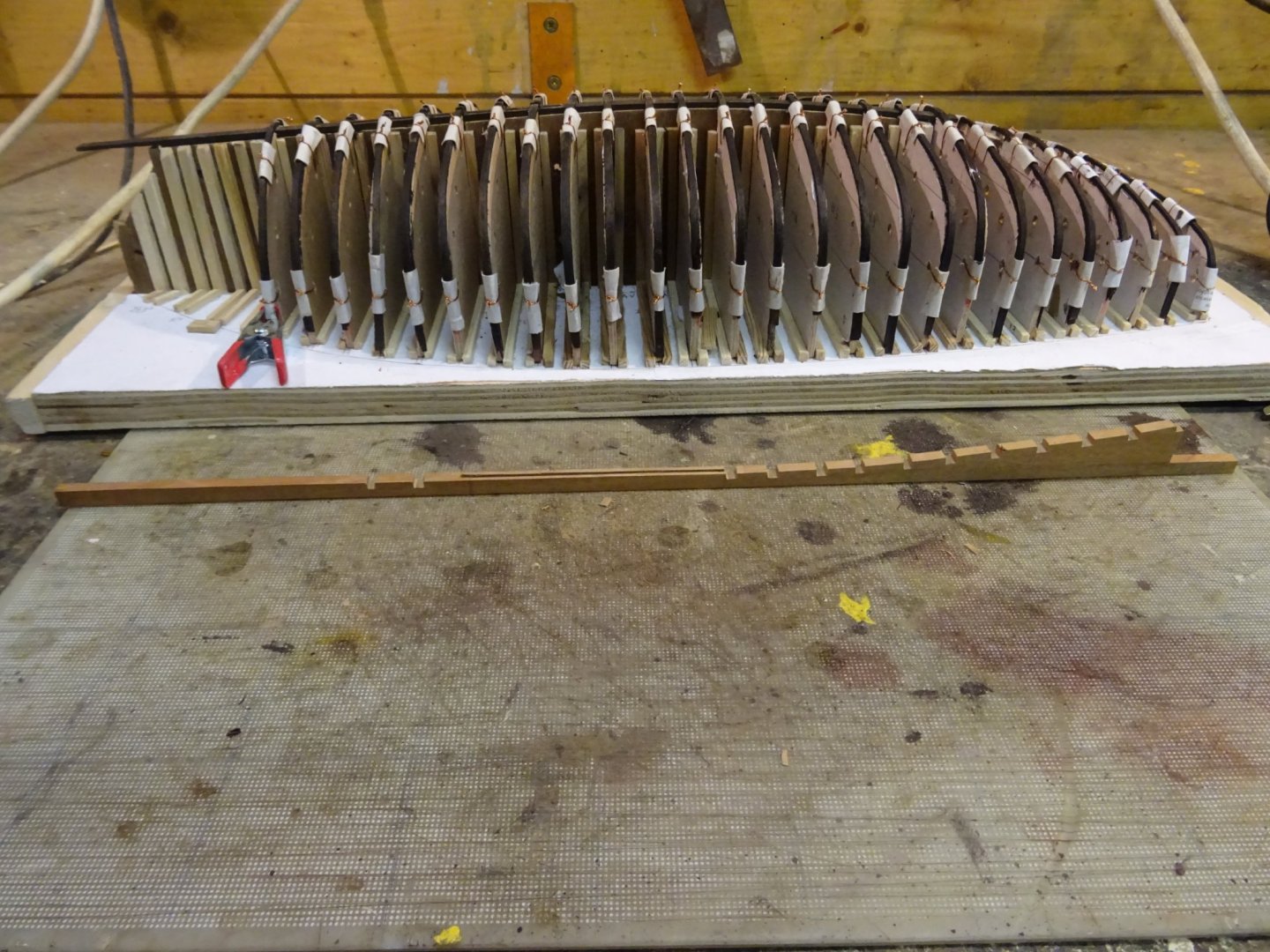
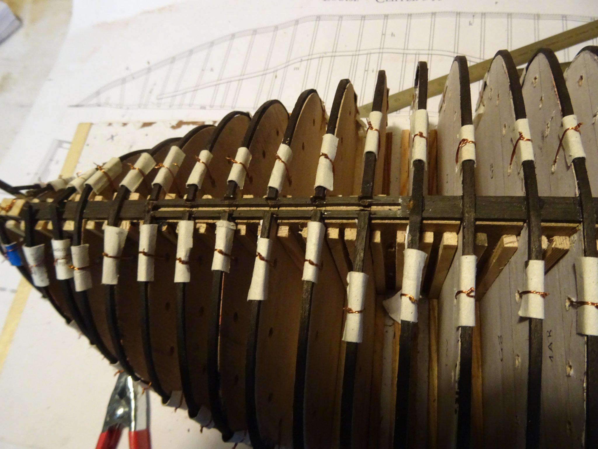
It can now be sanded. I use the 3mm thick template as thickness jig.
With the sanding some of stain disappeared. When it is re-stained, I place the frame back on the template and on the building board. A piece of card protects the spots where the wire is tightened.
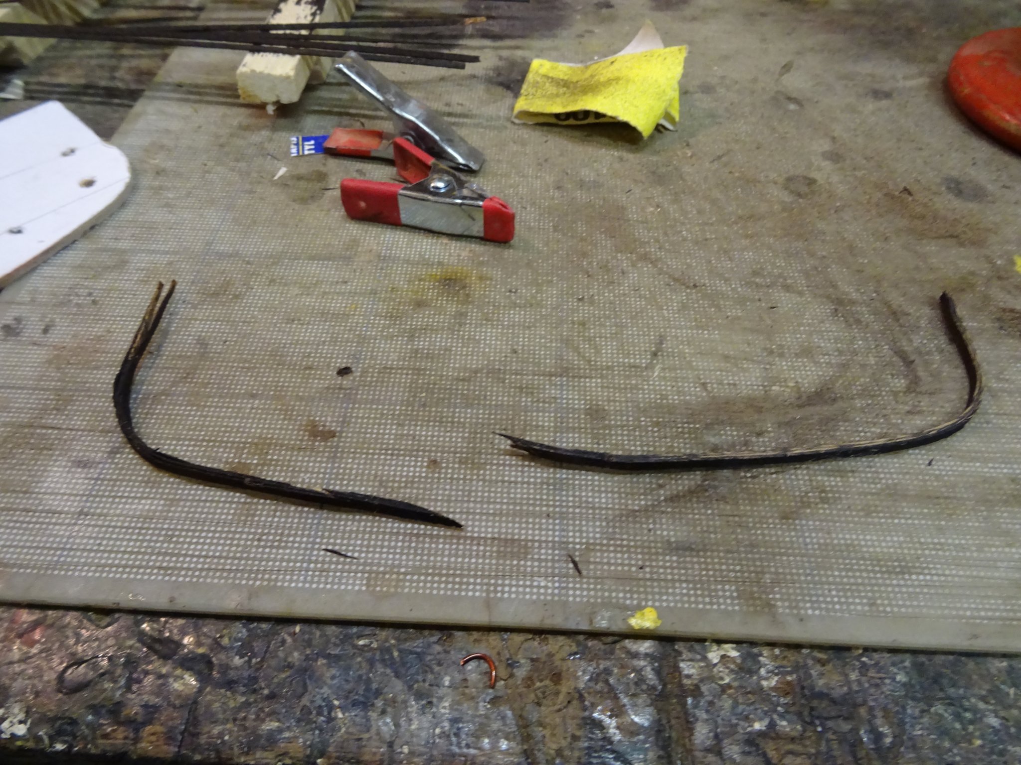
Oops! Not been careful enough when sanding.

That's it for this week. Nine frames are finished and two re-laminated after being broken during the sanding.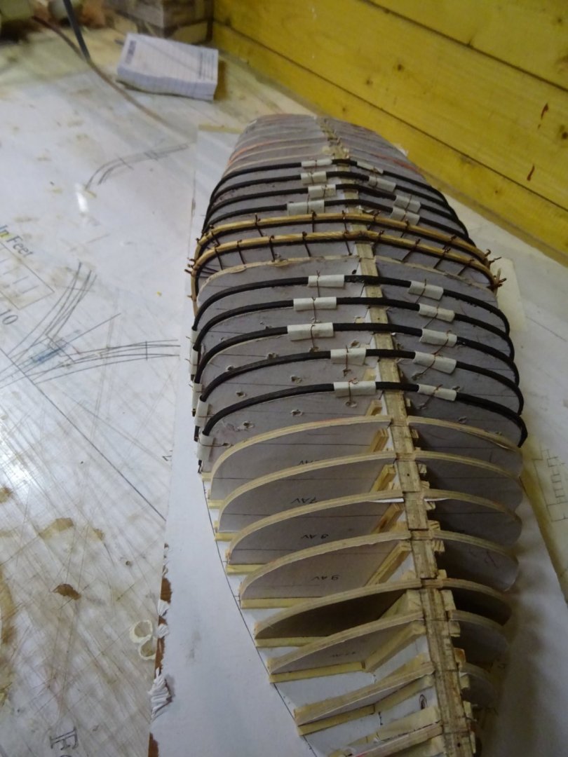
Thank you very much for reading this log, for your likes and for all your interesting reactions.
Till next week!
- JpR62, Wintergreen, Baker and 12 others
-
15
-
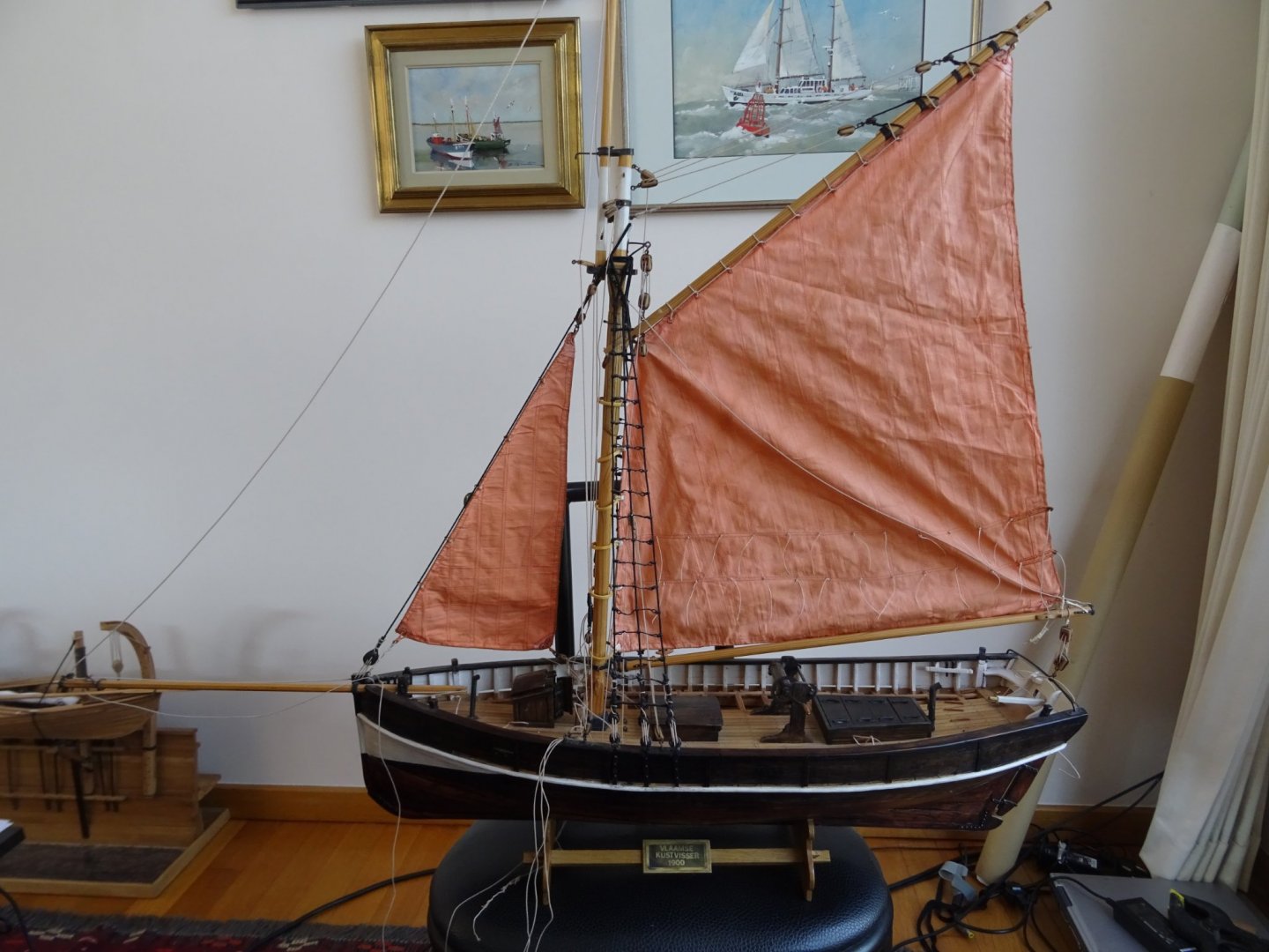
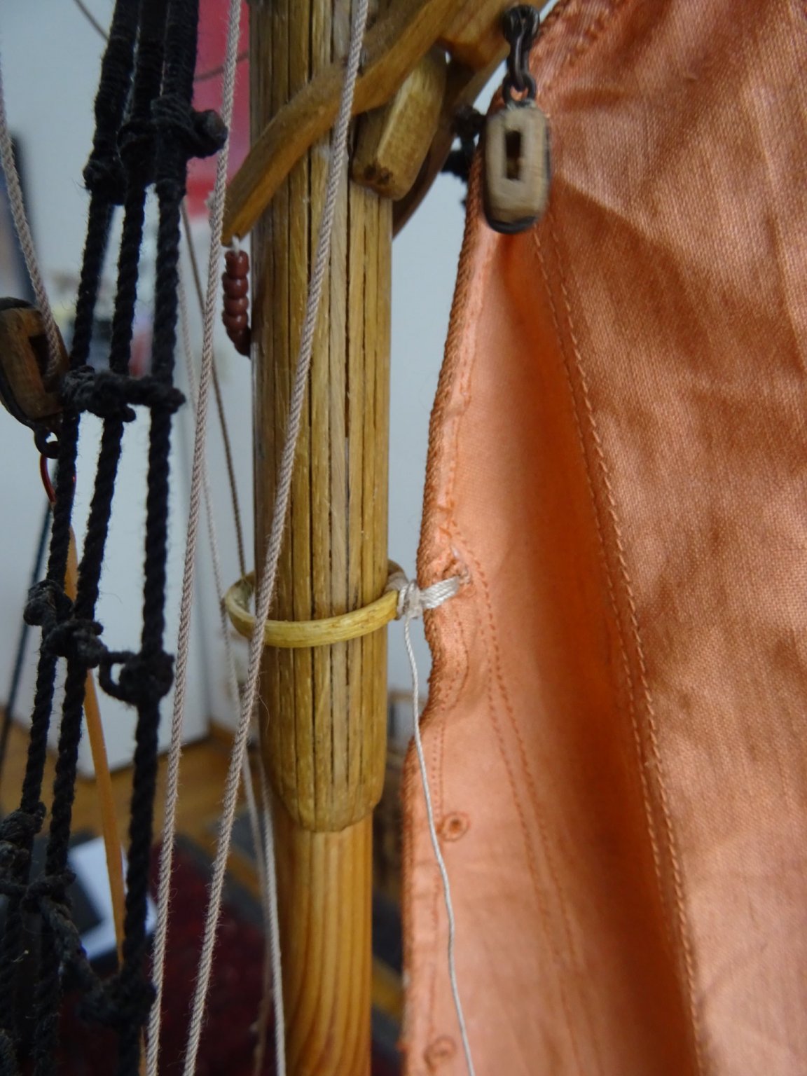
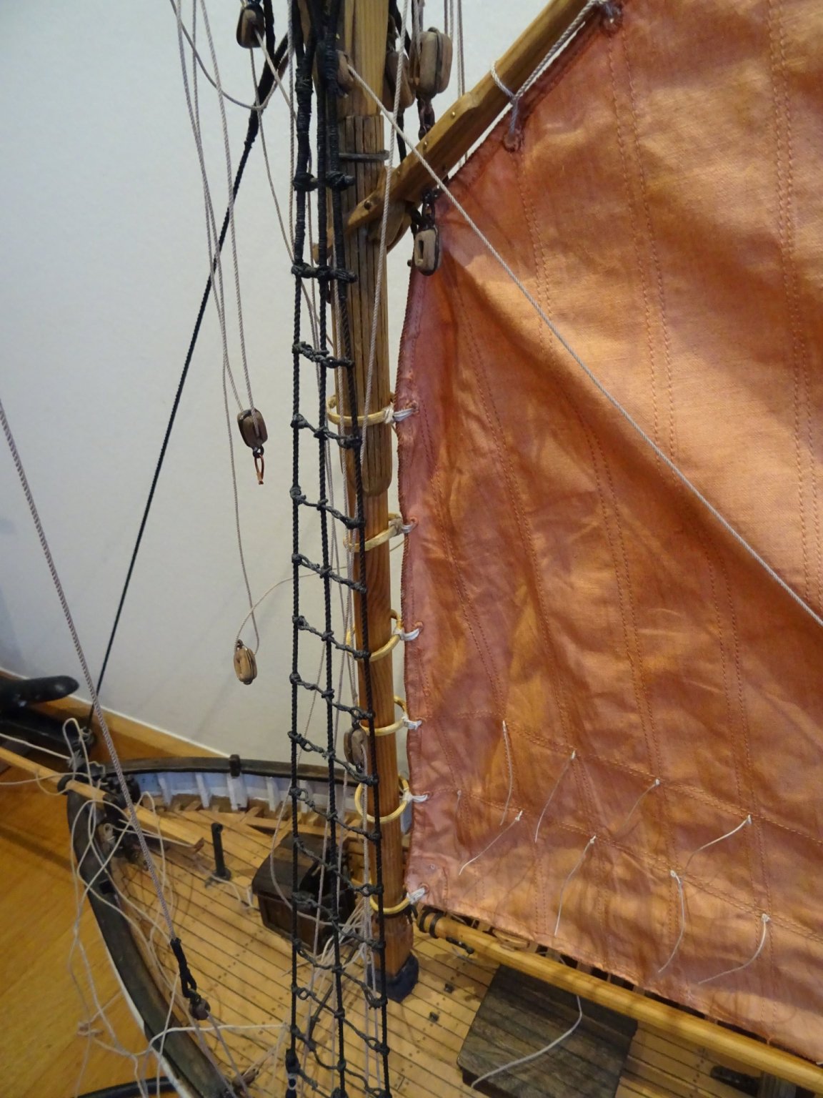
Now it is time to hang the main sail on the spars. I fix it first to the gaff. It is marched with a rope.

The main sail is attached to the mast with six mast hoops. Sewing the sail to the hoops.

All six hoops are sewn.

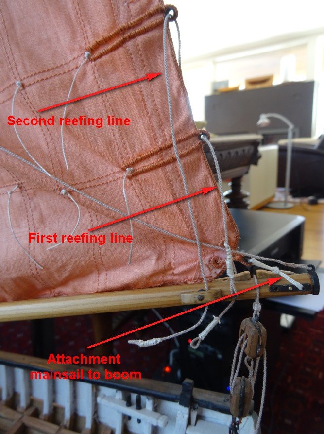
The mainsail is secured to the end of the boom with a ligature. On the picture you see also already the two reef fair lines, but I will finish the reefing installation a bit later and describe it then.
Thank you for reading this log, for your likes and for your constructive comments.
Till next week!
-
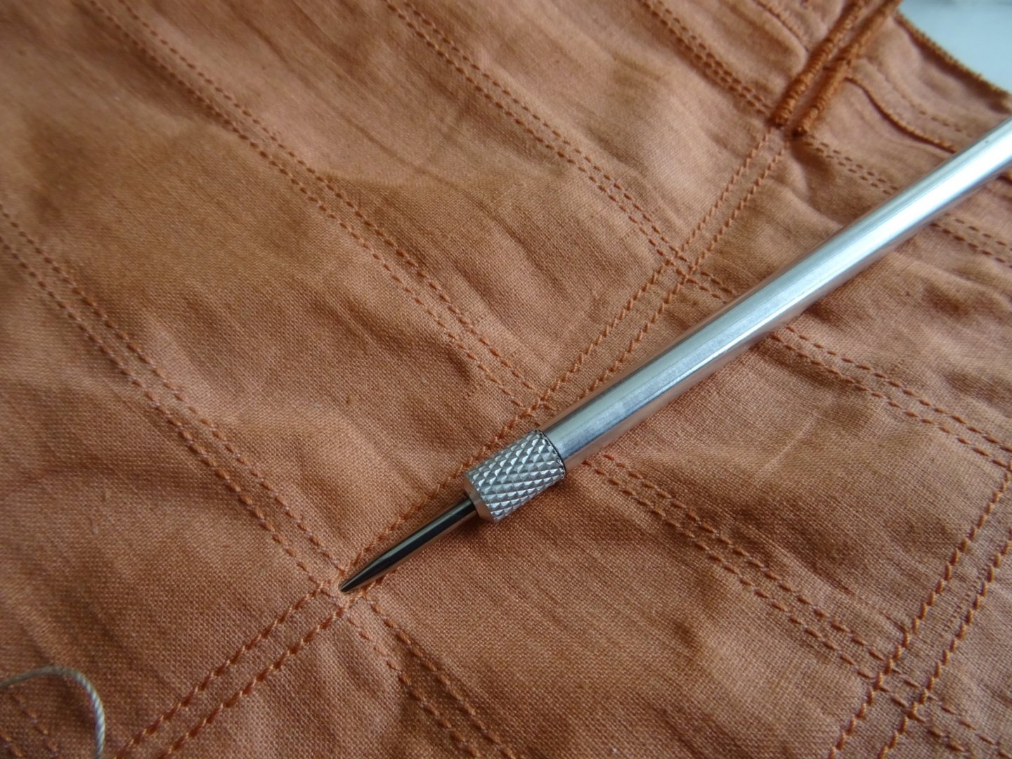
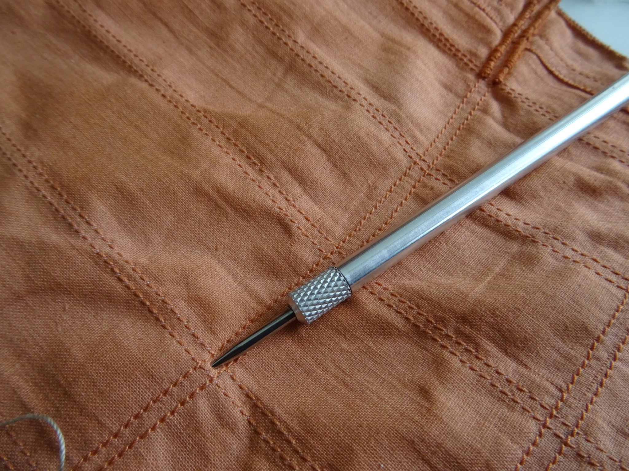
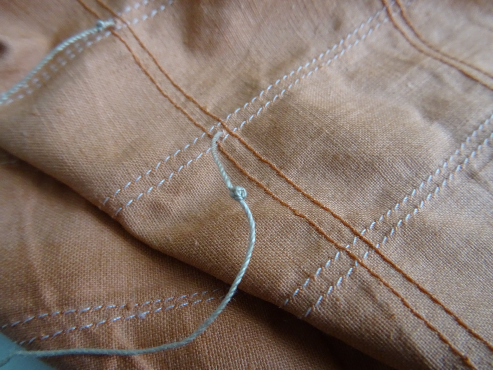
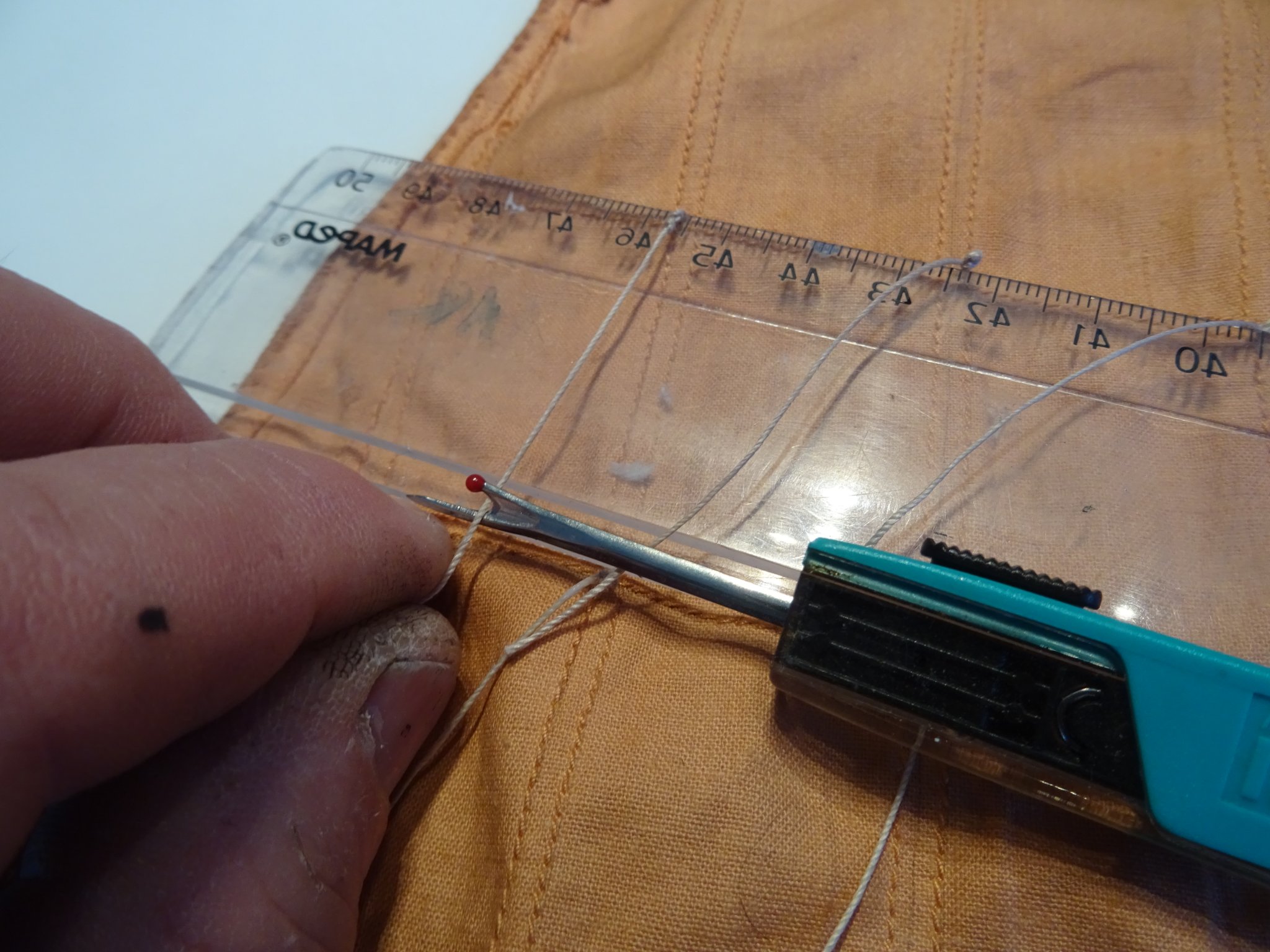
Before hoisting the main sail, I have to fix the reef lines. I punch the holes for the lines through the sail with an awl.
I put the line through and tie a knot to block it. At the other side of the sail comes also a knot.
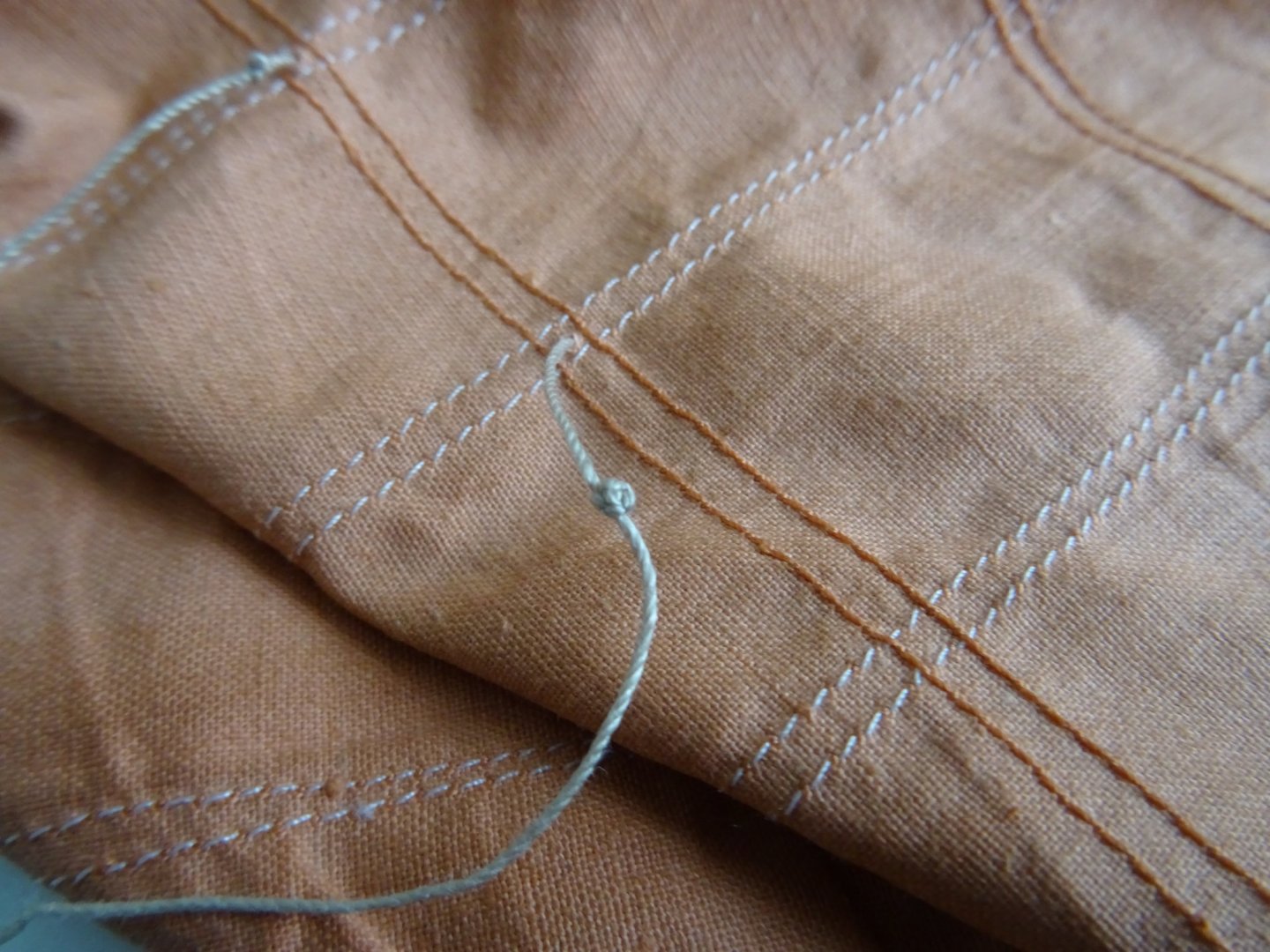
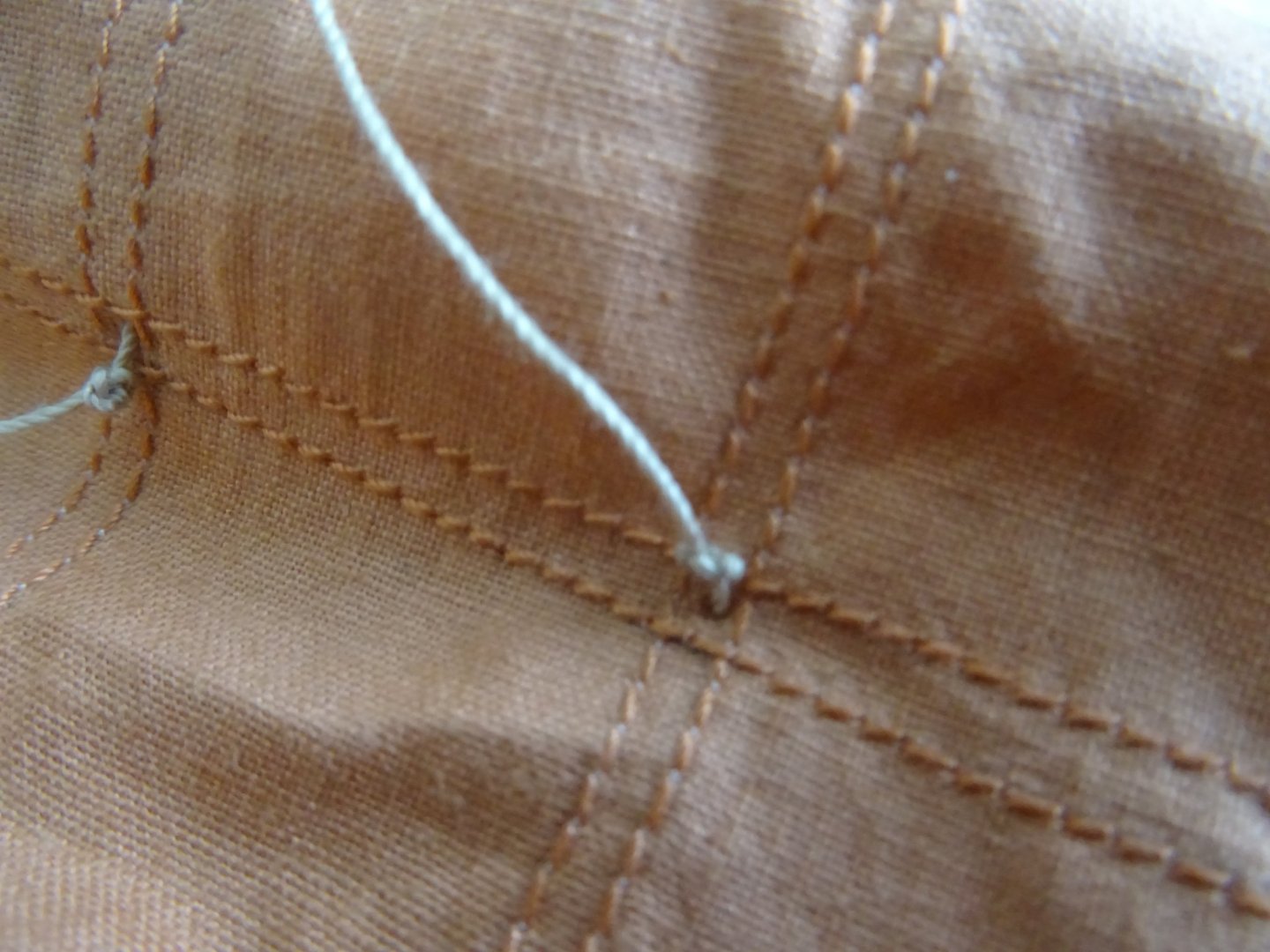
I stretch the lines and fix them with textile glue.
Then I cut them to length.

- Baker, GrandpaPhil, wefalck and 1 other
-
4
-
13 hours ago, Redshirt said:
Thanks for the answer. The problems that frames which have been reconstructed from the waterlines do not fully match the frames given by the monograph as well as inconsistencies between different plans of a single set are something i have experienced far too often with some of the more recent Ancre monographs.
In the age of cad software this should no longer happen.
Perhaps it is a phenomenon that has occurred since the use of CAD technology?🤔
-
13 hours ago, Redshirt said:
What a beautiful start for a beautiful boat.
Allow me a question. Most of the recent Ancre plans left me somewhat (or in some cases, very) disapointed. How is this one?
Was it easy to draw the frames or did you had to correct much?
Redshirt,
I want to be a little careful with my answer to this because it is my first time working with Ancre plans and I have a lot of friends who are very satisfied with Ancre.
I find the plans very detailed and suitable to work with, but now that you mention it here, I remember a few things that struck me:
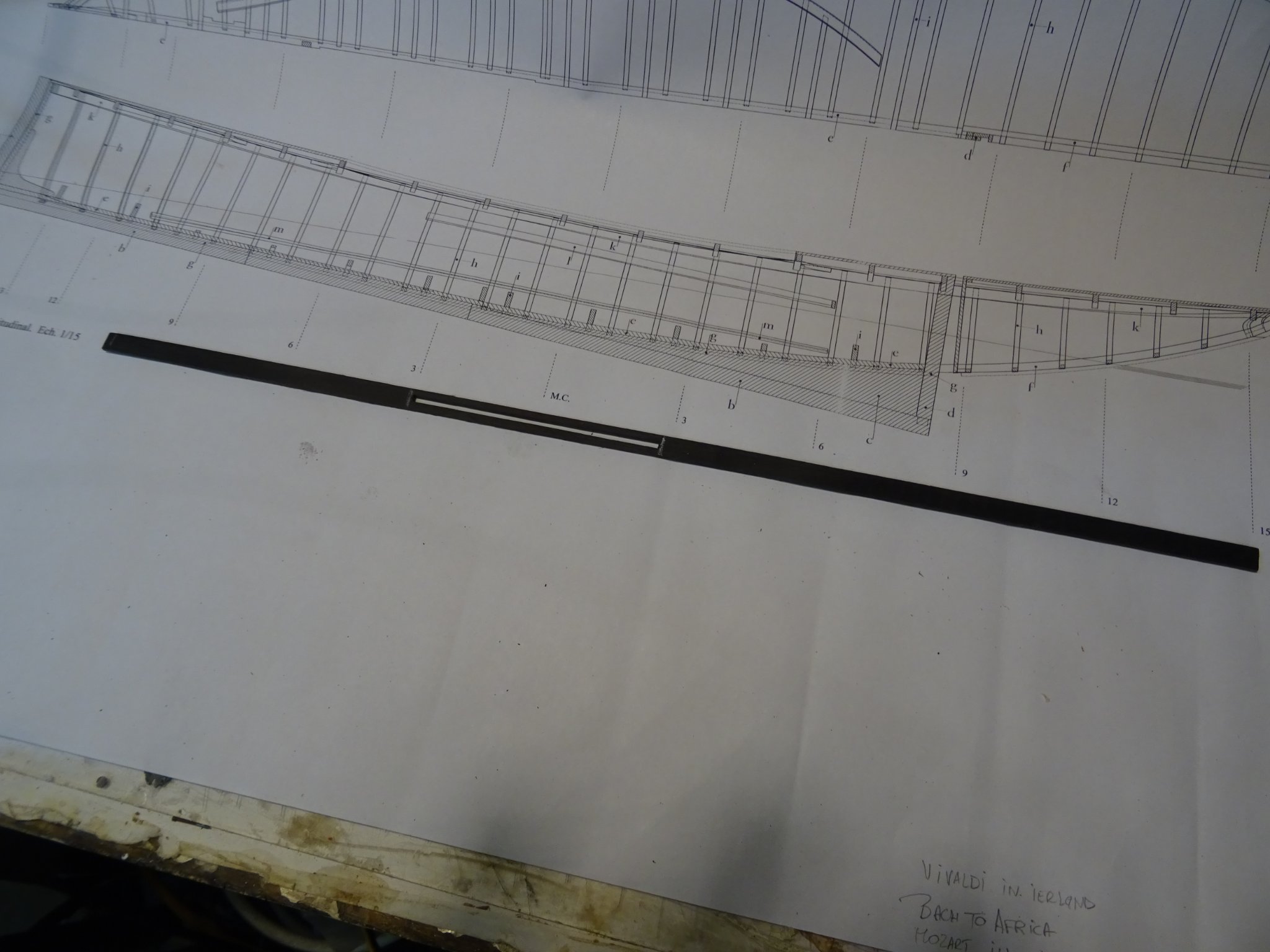
- To make 29 frames, 29 templates have to be made, which is why I expected that all 29 drawn out would be found in the plans. However, only 11 frame drawings are available. The rest must therefore be drawn yourself.
-
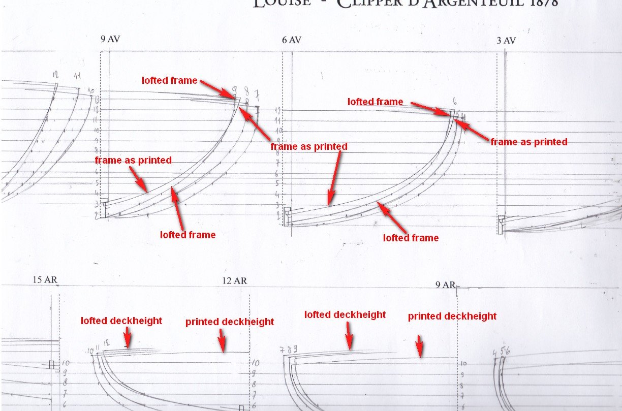
When drawing the frames, I arrived at a slightly different shape from the one in the plans. On my first frame I thought the fault was mine, but it occurred with every frame. I also noticed that the deck heights behind the main frame on my drawings were a few mm higher than those on the plan. I do not rule out that I drew the frames incorrectly, but I still have my doubts about that.
-
What I don't have doubts about:
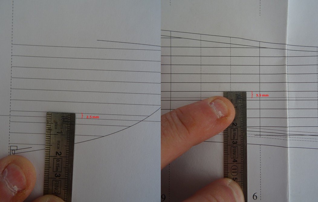
There is an inaccuracy in the height of the waterline on the plan. On the frames in front of the main frame, the waterline on the frame plan is 1 mm higher than behind the main frame.
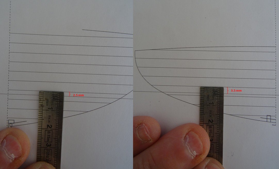 In the lines plan, the waterline is at the same level as for the frames behind the waterline. I have therefore assumed that height as correct.
I think it is a pity that the monograph does not give any indication about the method and techniques to be used to build the model.
In order not to present it all negatively here, I would like to emphasize that despite what I wrote above, the plans are very useful and that I enjoy working on this model so far and that it will undoubtedly still have many challenges for me in store.
-
On 3/30/2021 at 8:21 AM, Backer said:
Are "sea tourists" with experience on ferry boats and cruise boats also allowed to follow 😉.
As always, a very instructive and educational build 👍
Patrick, sea tourists with experience on ferry boats and cruise boats are the perfect audience for this log, welcome!
-


Golden Hind (ex-Pelican) by Baker - FINISHED - scale 1/45 - Galleon late 16th century
in - Build logs for subjects built 1501 - 1750
Posted
Looks like you've had a busy week, Patrick.