


G.L.
-
Posts
1,553 -
Joined
-
Last visited
Content Type
Profiles
Forums
Gallery
Events
Posts posted by G.L.
-
-
Conclusion
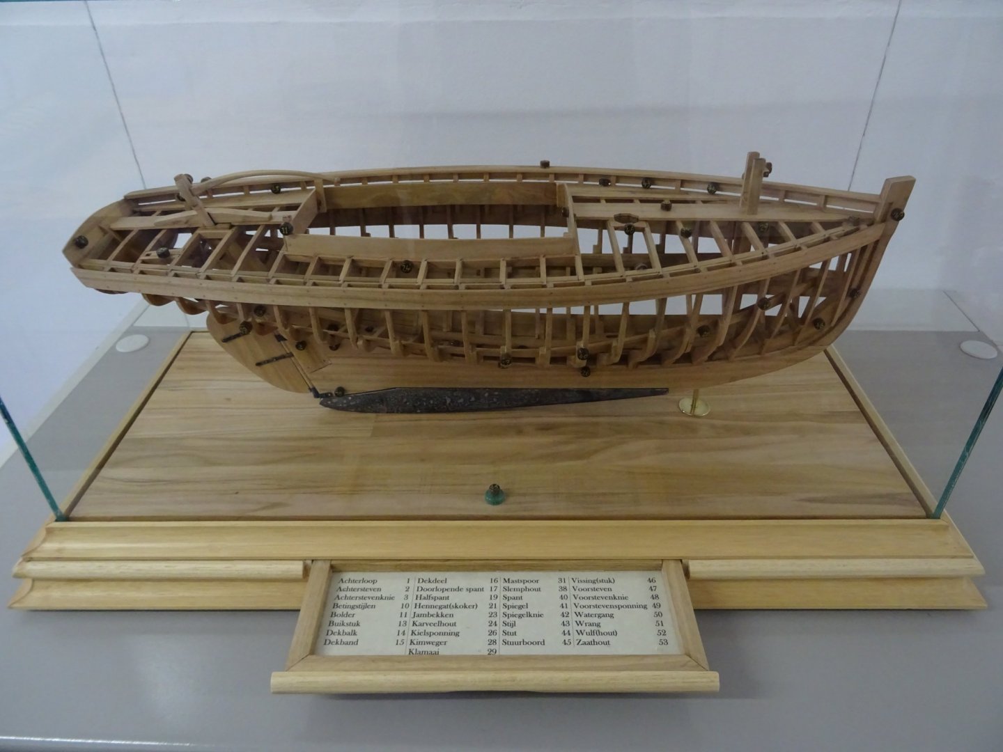
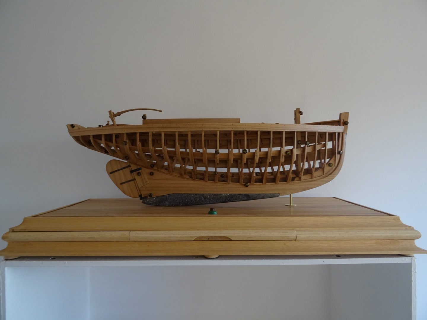
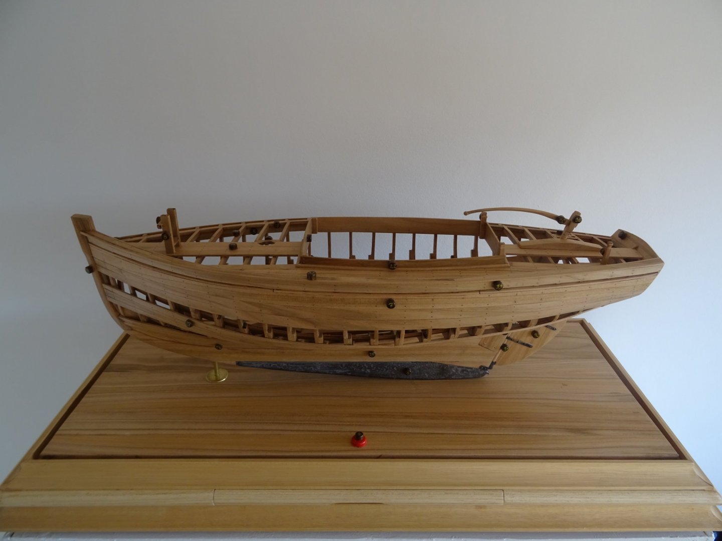
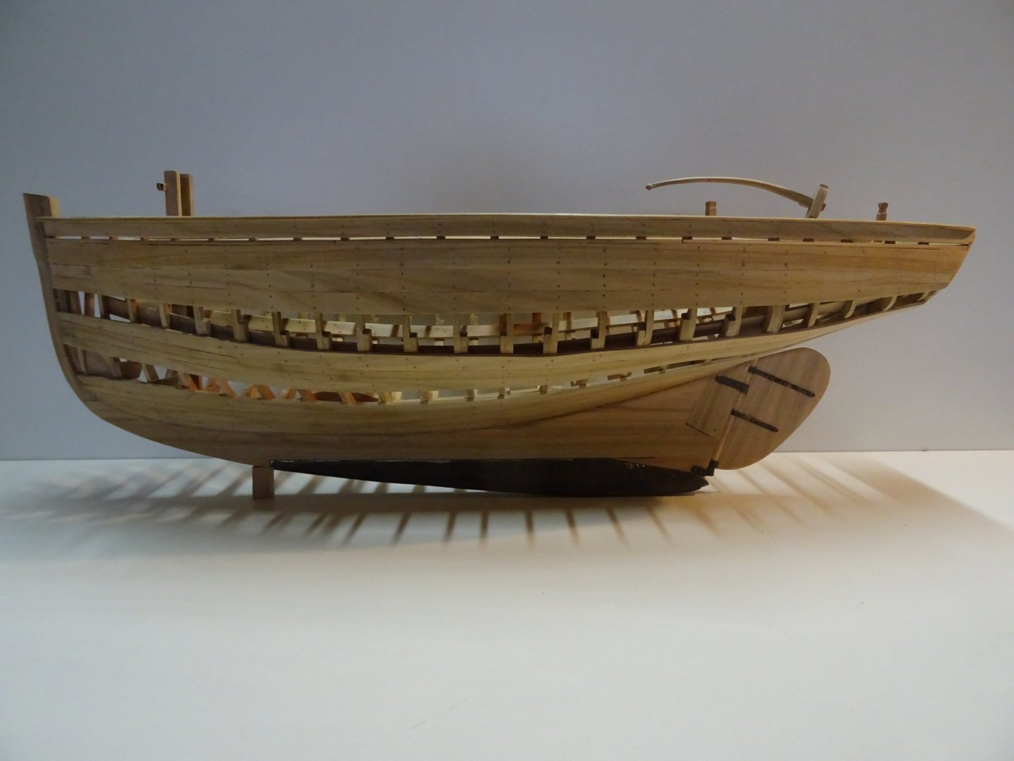
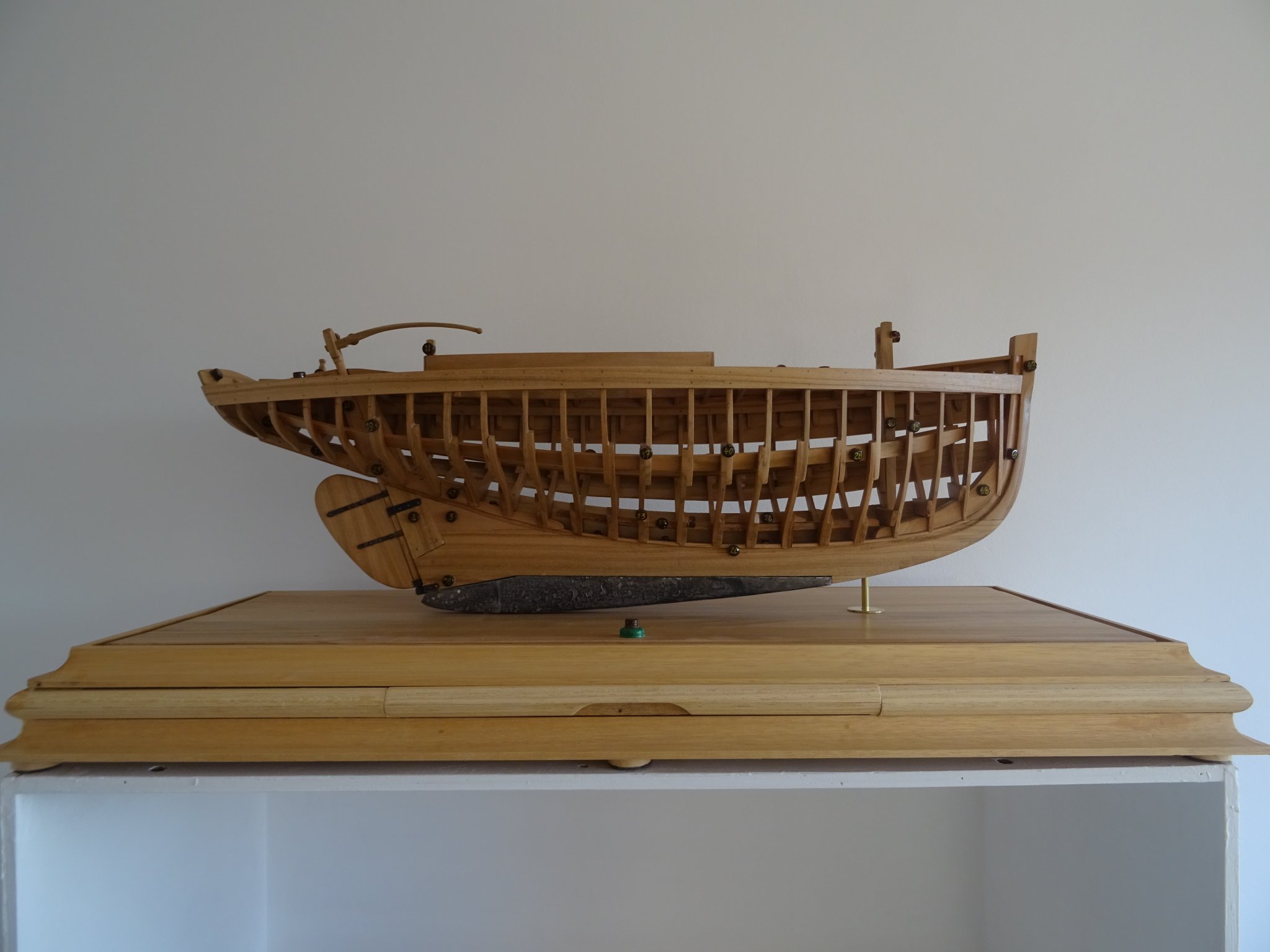
Here my project ends: Anatomy of a boat.
This model has been built for nostalgic reasons to the era that the ship model was a common didactic tool in maritime education.
The vessel that was the subject of my project is a small Breton mackerel cutter. A detailed practicum and construction drawings to build this model are made by Mr. Gerd Löhman and published in the book 'Apprendre le modélisme naval' of Le Chasse-Marée/ArMen. New editions of the book are out of stock, but it can currently be found on the second hand market.
The model was a real pleasure to build, a real recommendation.
I thank you all who read my log. Your interest and your encouragement gave me a positive boost. Thank you all for that.
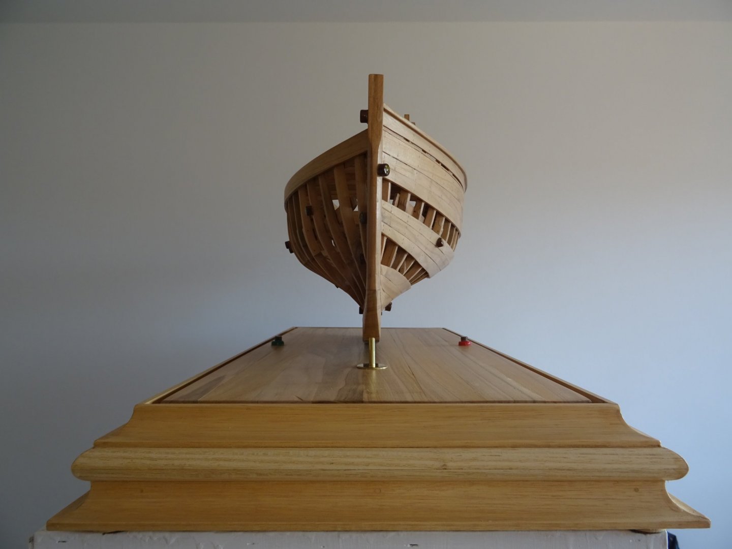
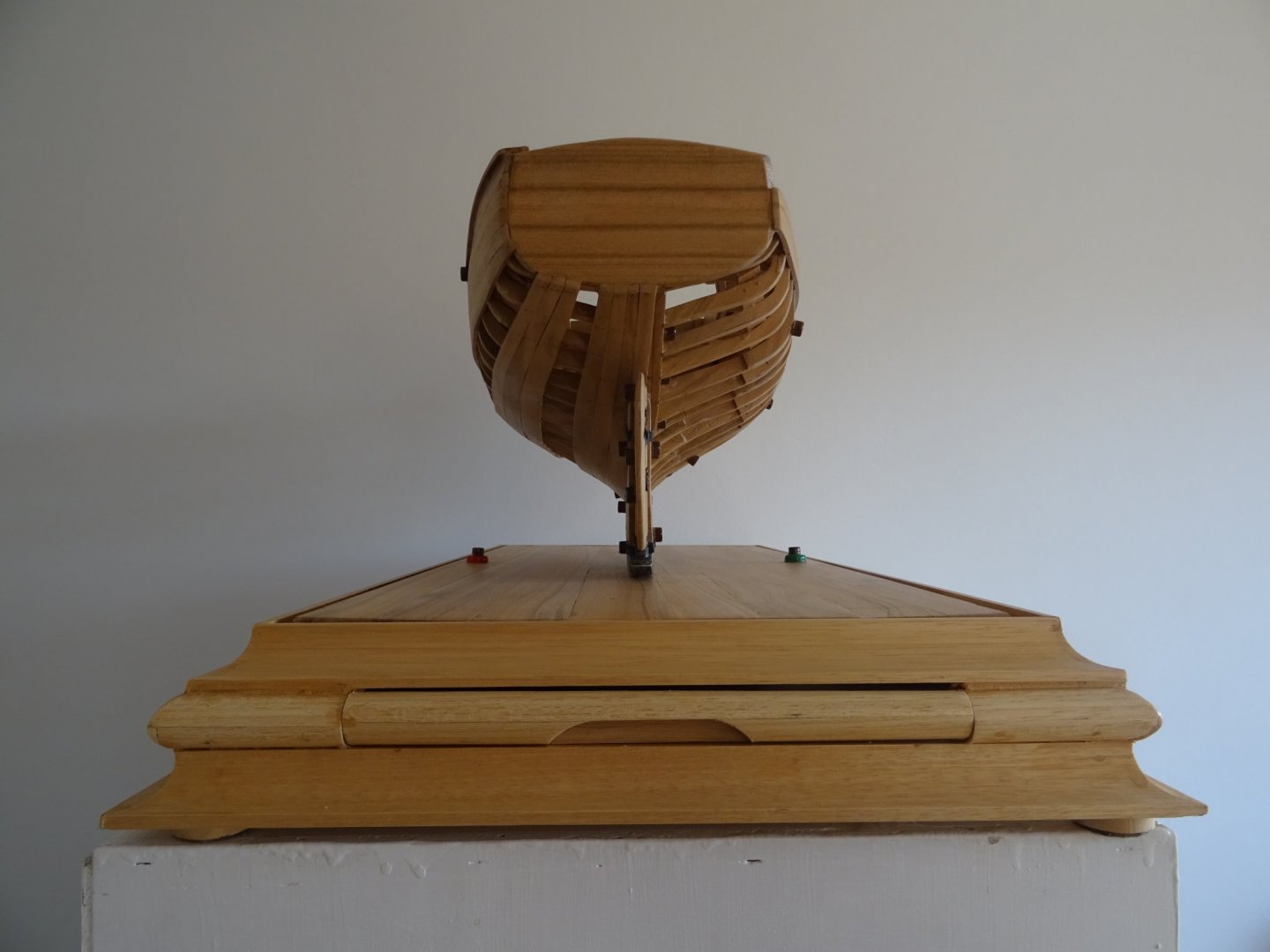
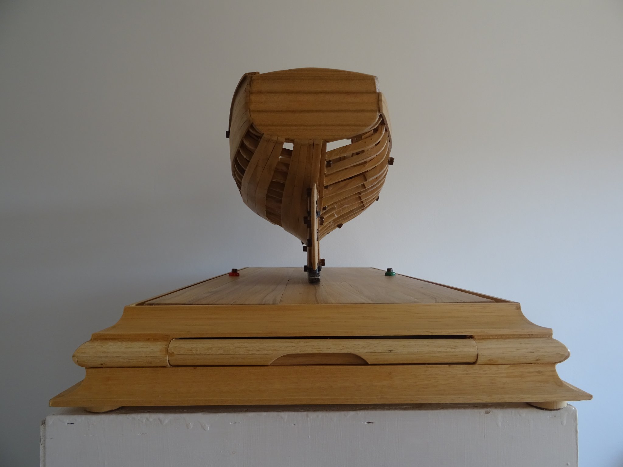
Below some more pictures of 'The anatomy of a boat'


-
Thank you very much Ward, Keith, Mark, Druxey and Patrick. Thanks a lot also for all who pushed the like button.
Let's make a run the the end of this project now:
CHAPTER III: The Encyclopedia.
It would be nice that my students can name the 54 listed parts, but I am a demanding teacher, so naming the parts is not enough for me. My students must also be able to describe the parts and they have to know the function of it.
During the build of the model I kept a list in MS Excel of the different parts of the boat. I include in the list the translation of the named parts in English and in French because that are the languages of the reference works that I use most beside the Dutch. For each part I note also a detailed description of the purpose and/or the structure.
The table in MS Excel makes it easy to sort the different components and to export the columns to other applications such as MS Word.

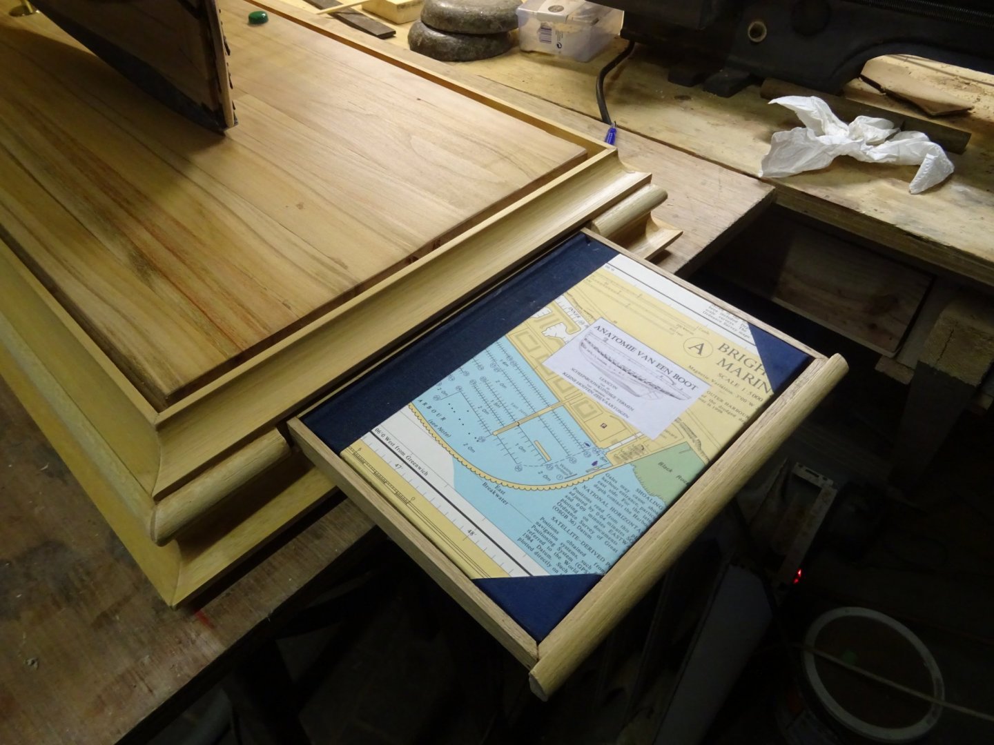
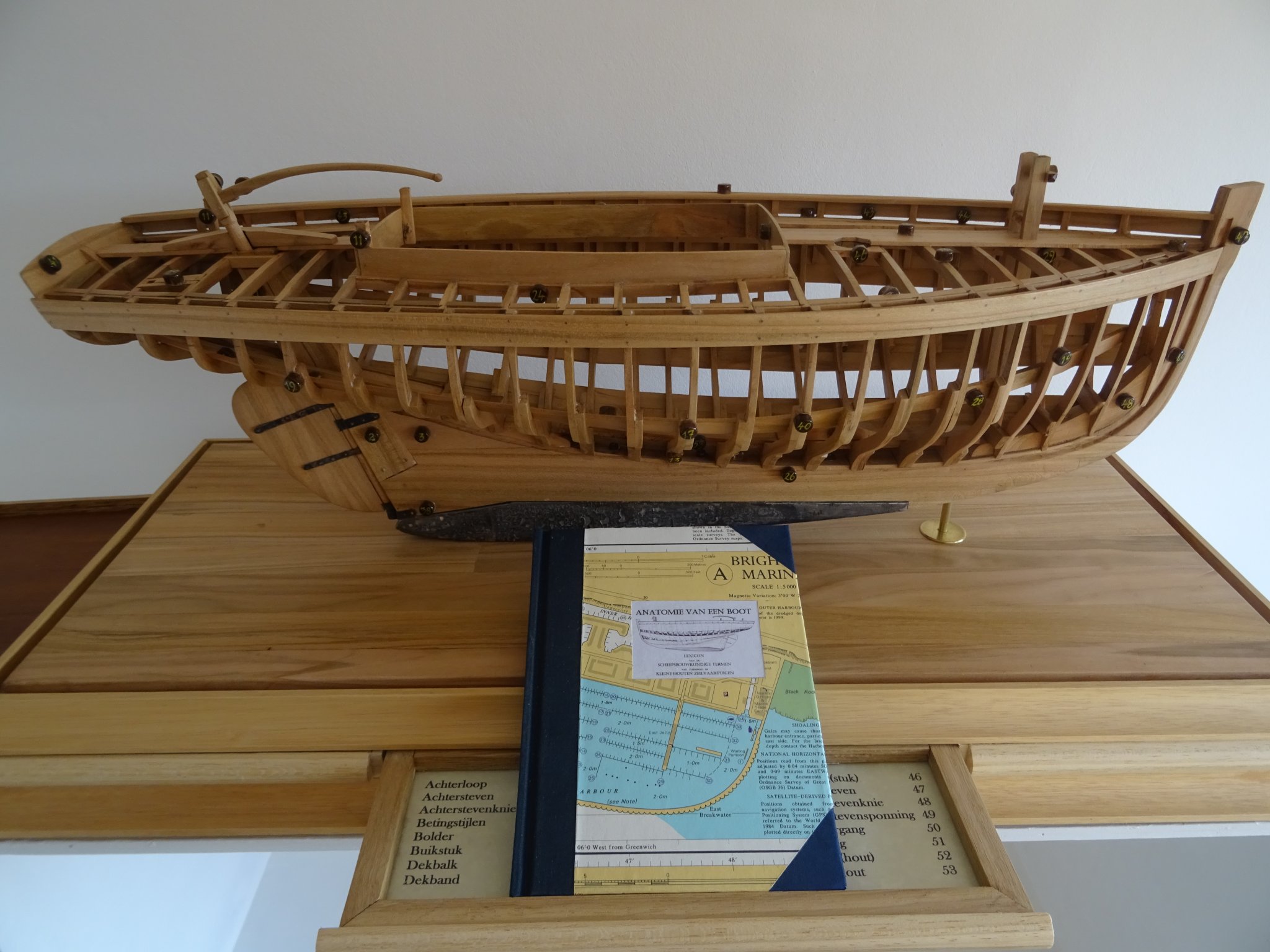
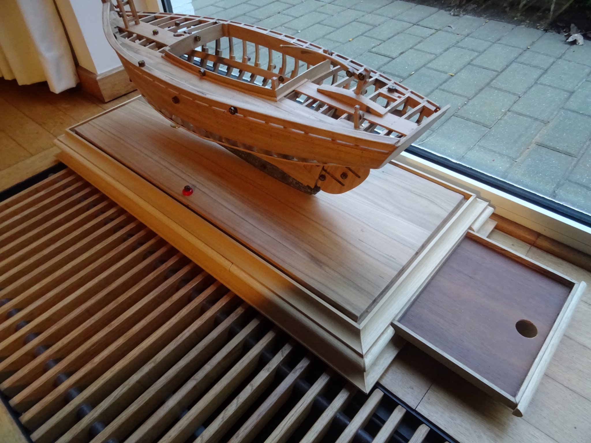
A third drawer in the display board is reserved for the encyclopedia. My encyclopedia will be a book, or better a booklet. The round hole in the drawer serves to lift the booklet easily out of it.

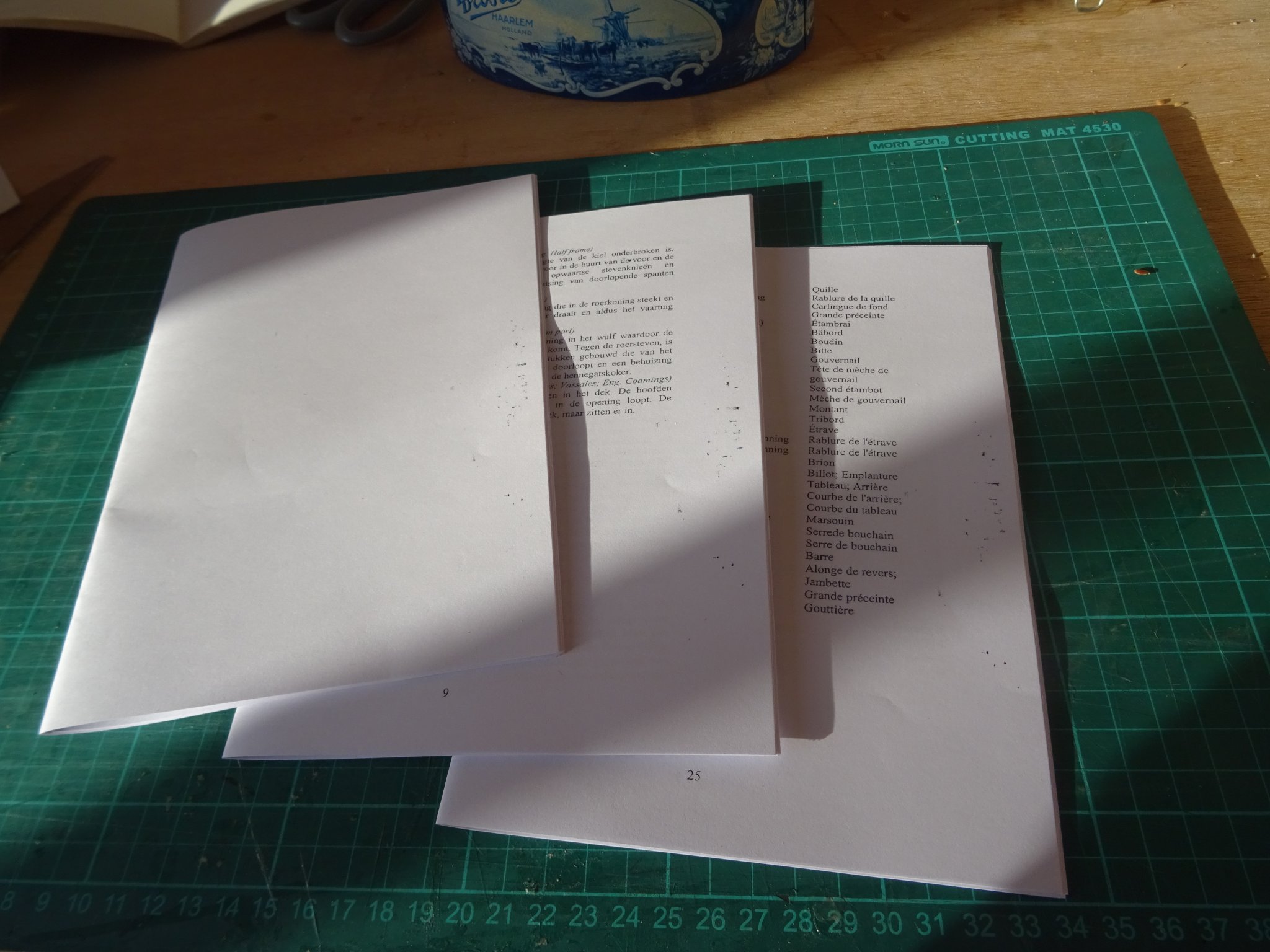
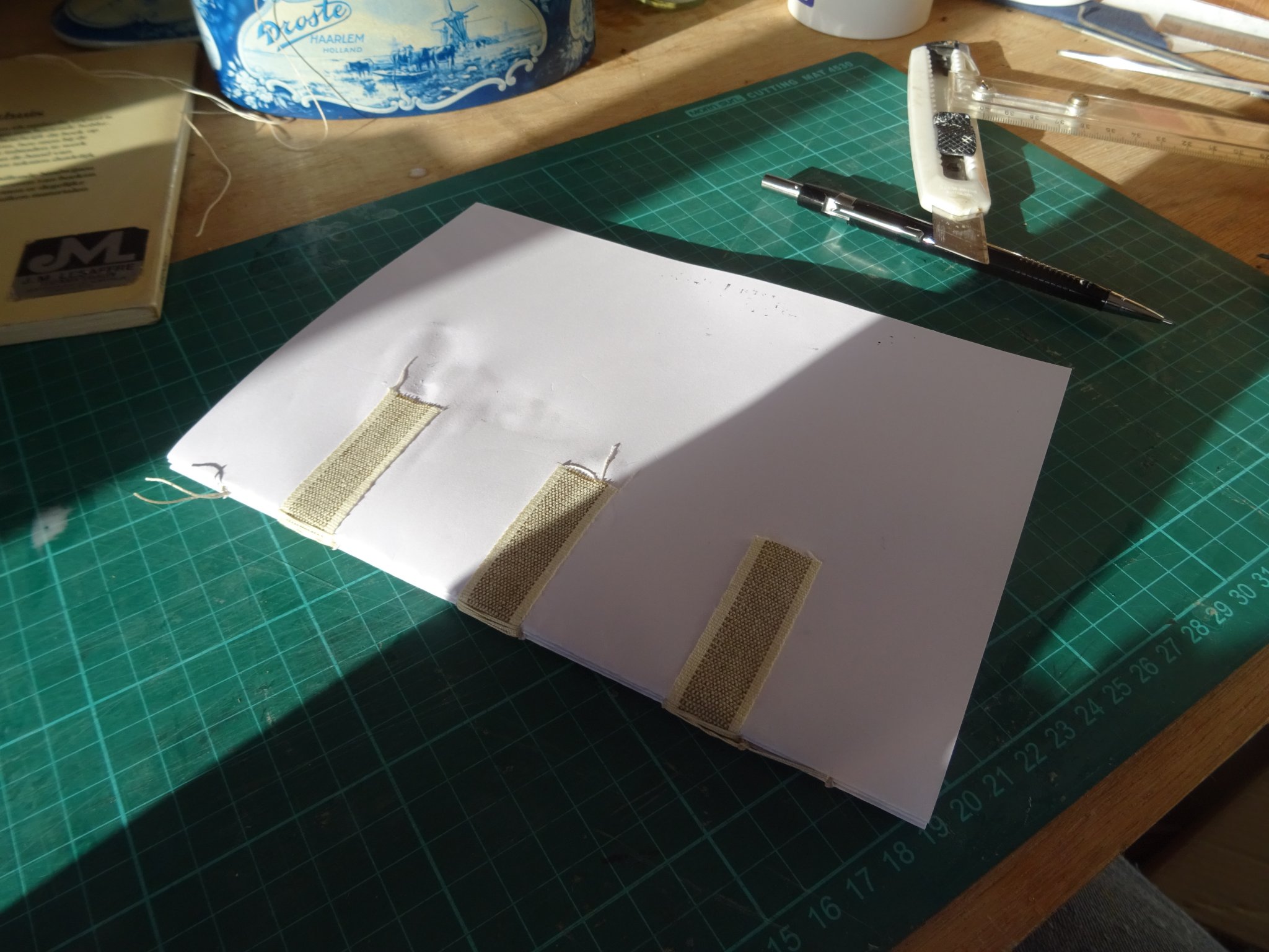
My Encyclopedia contains all the information of my Excel table an consists of three booklets of 12 pages.
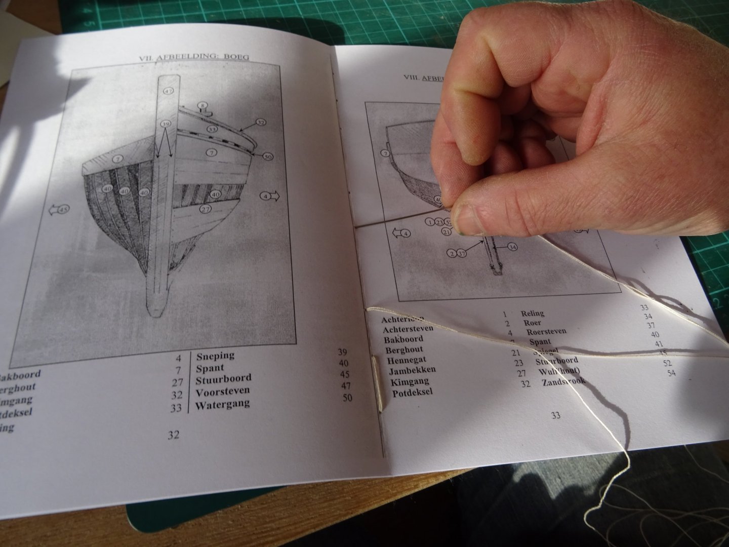
I sew them together on ribbons.

On the previous pictures you can see that my encyclopedia is illustrated. Before you start to think that I have an exceptional drawing talent, I will explain how I made the drawings.
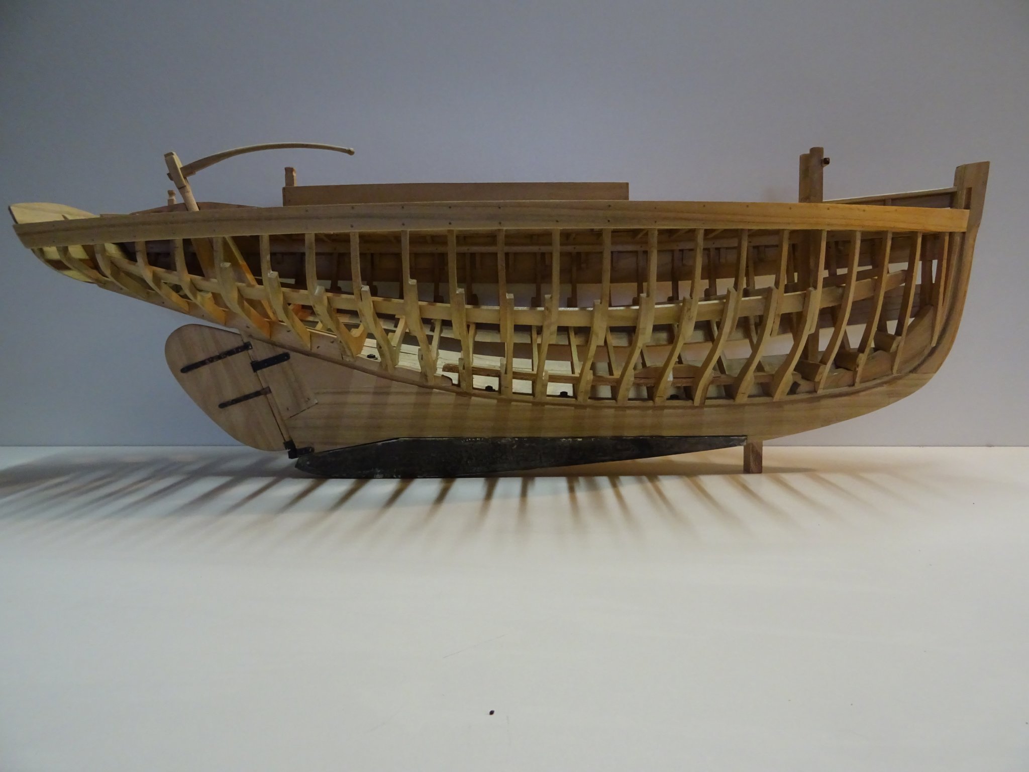
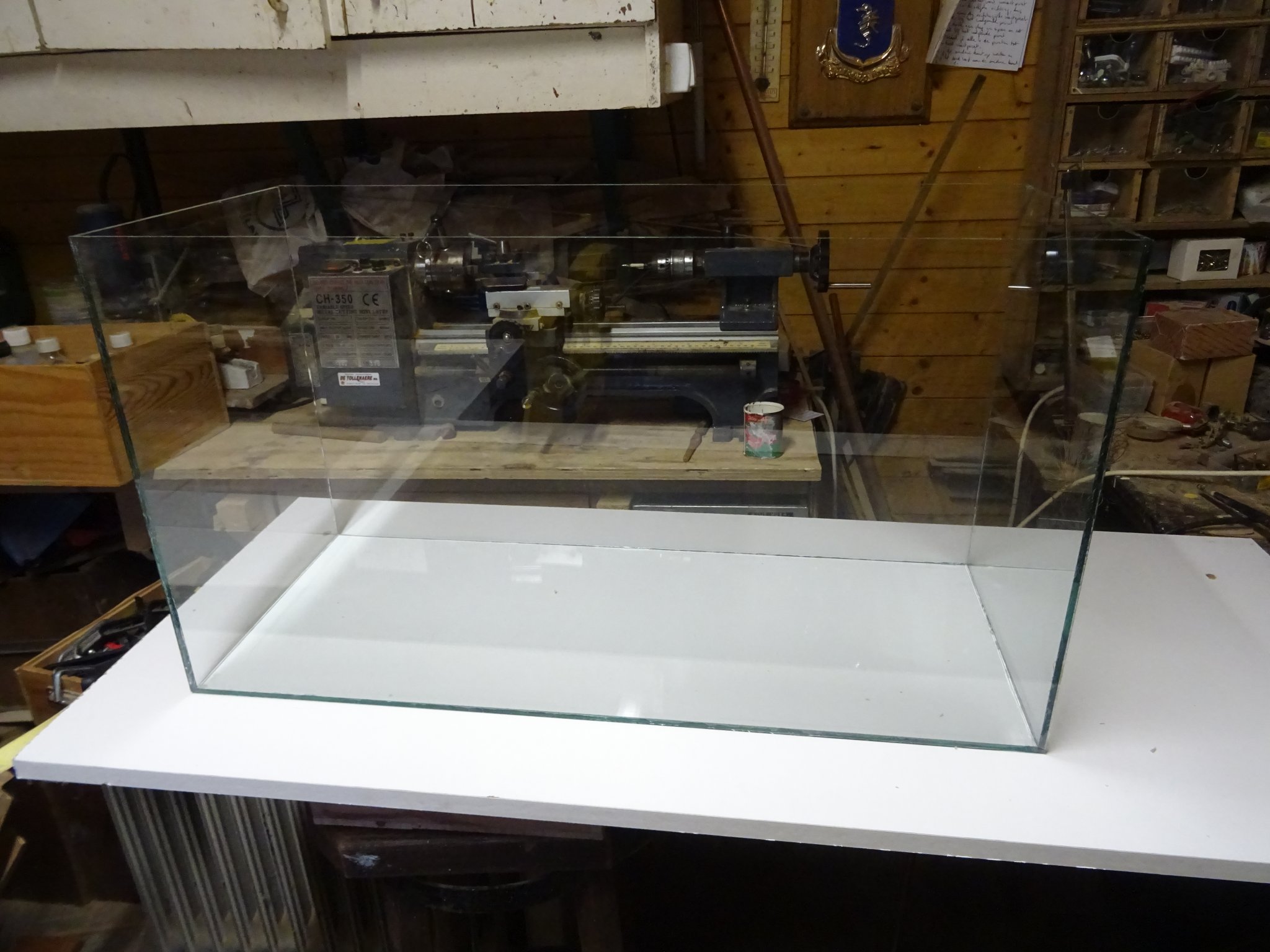
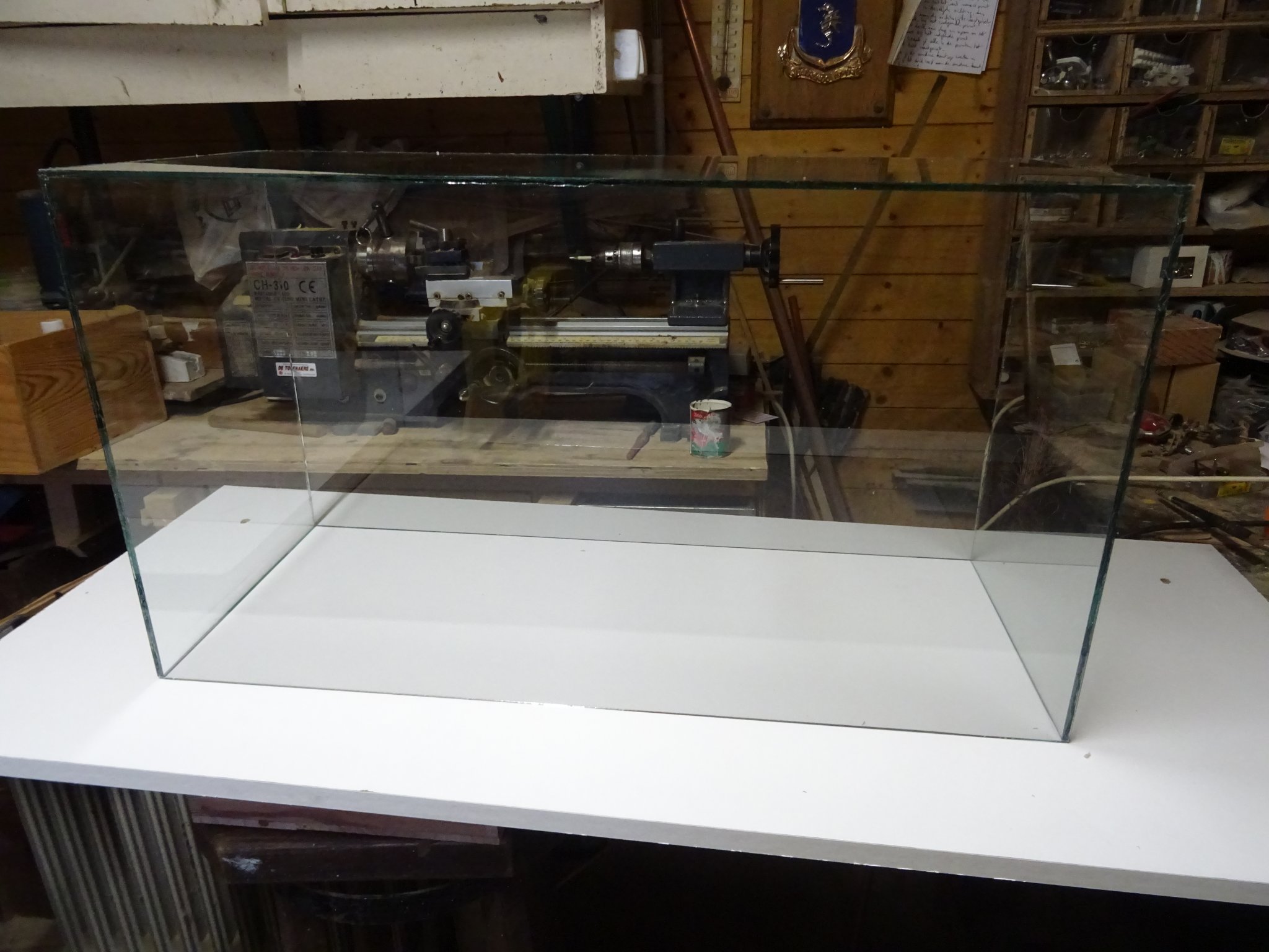
First I converted my workshop in an improvised photo studio to make some pictures of the model with a white background.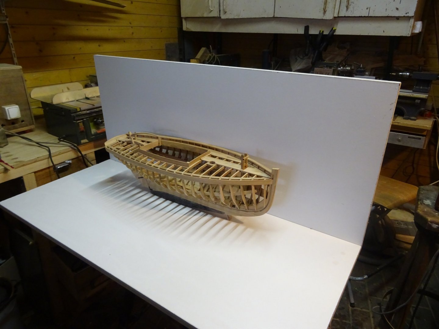

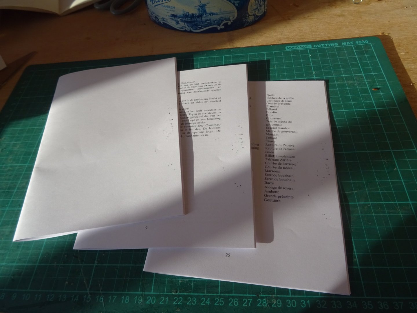
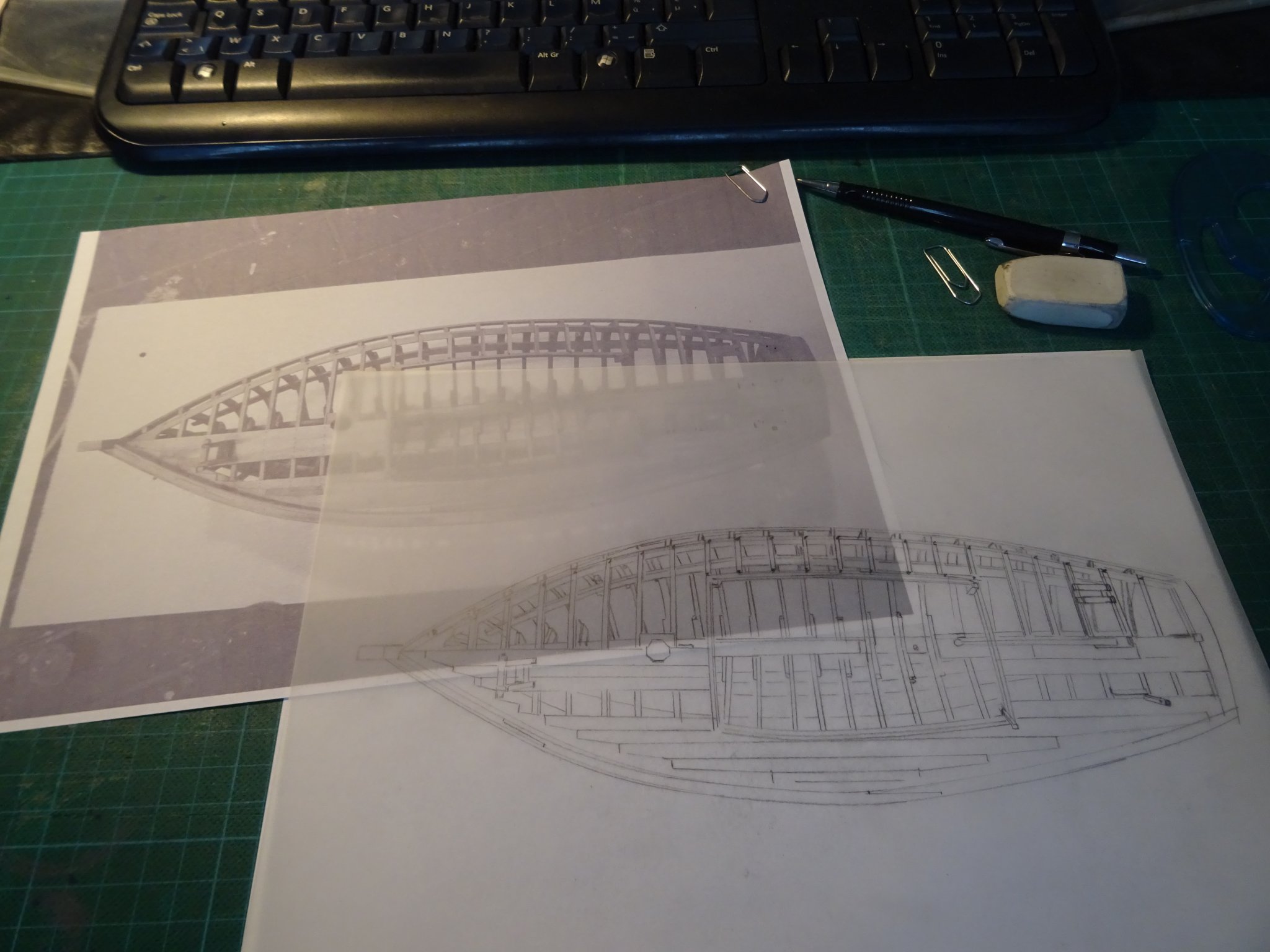
I print out the pictures and trace them over on tracing paper.
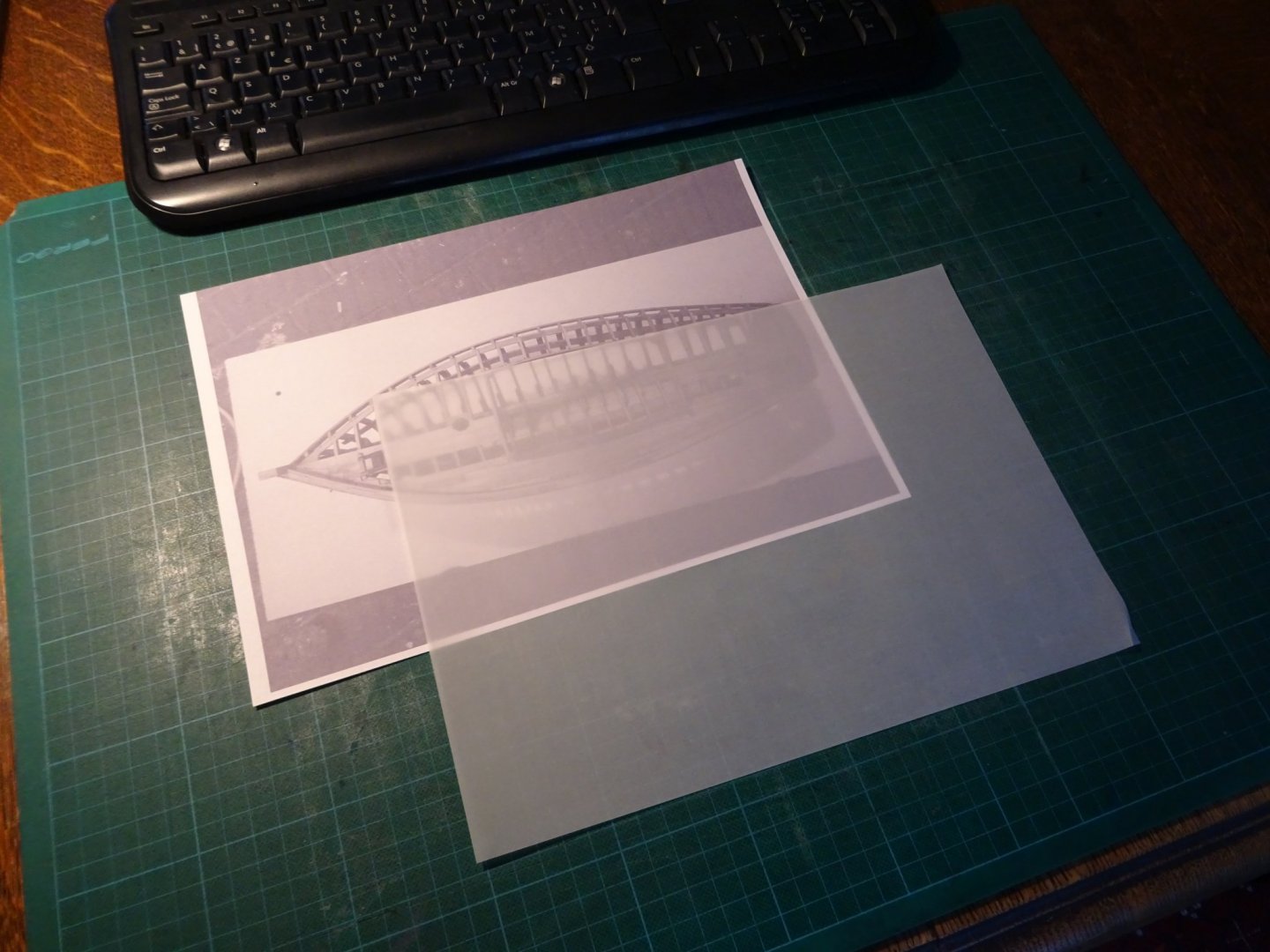

Then I ink the pencil drawing and my illustration is ready.
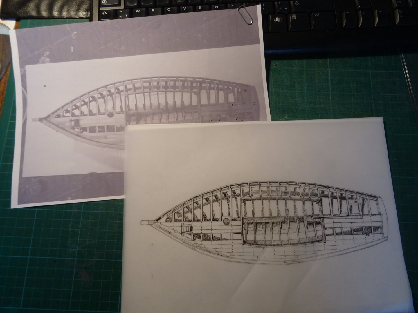
For those who wonder why I don't use the photos as illustration to save me the work of drawing. I Think that pen drawings fit more with the retro character of my instruction model than photos.
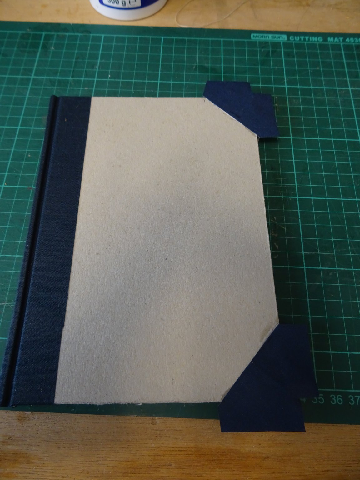
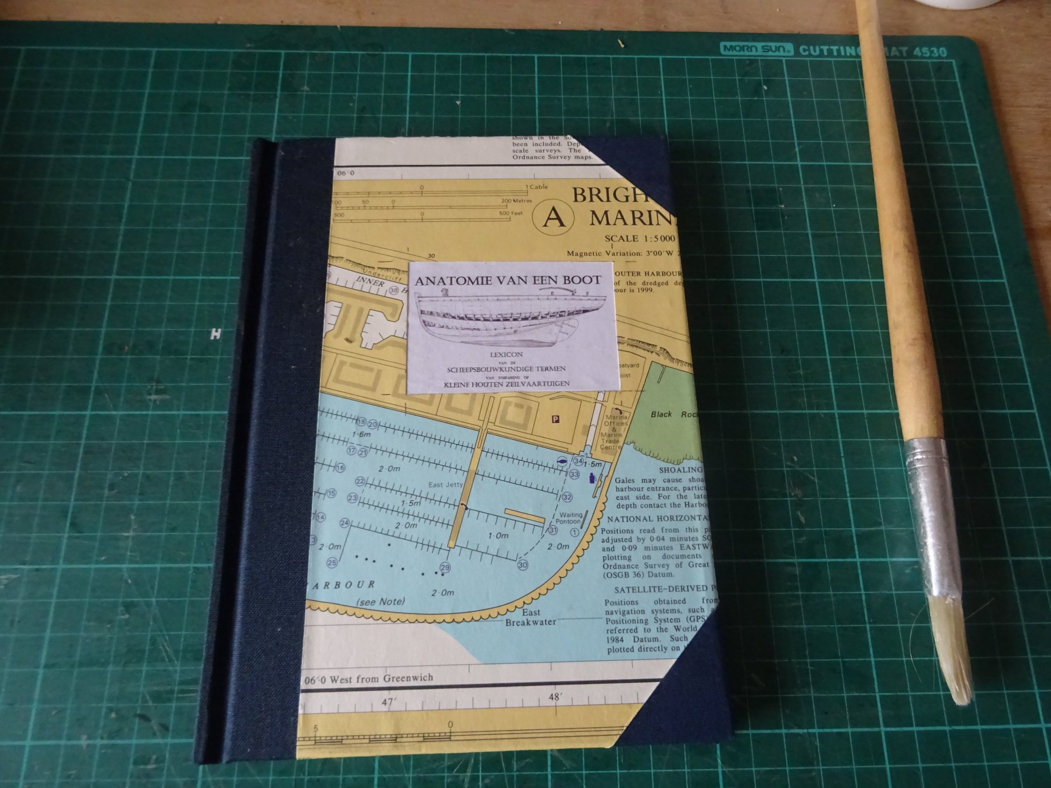
I finish the booklet with a cardboard cover and linen reinforcements on the back and on the corners.
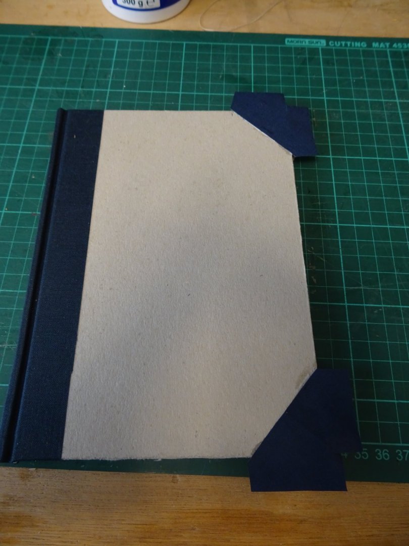
The final touch is a cover with a piece of old navigation chart.
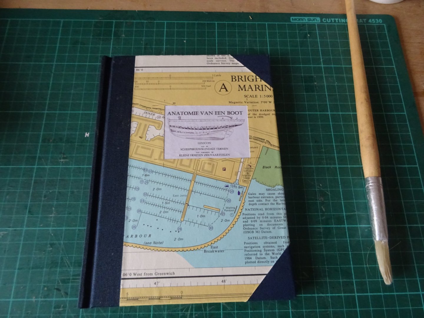
The Encyclopedia in its drawer.
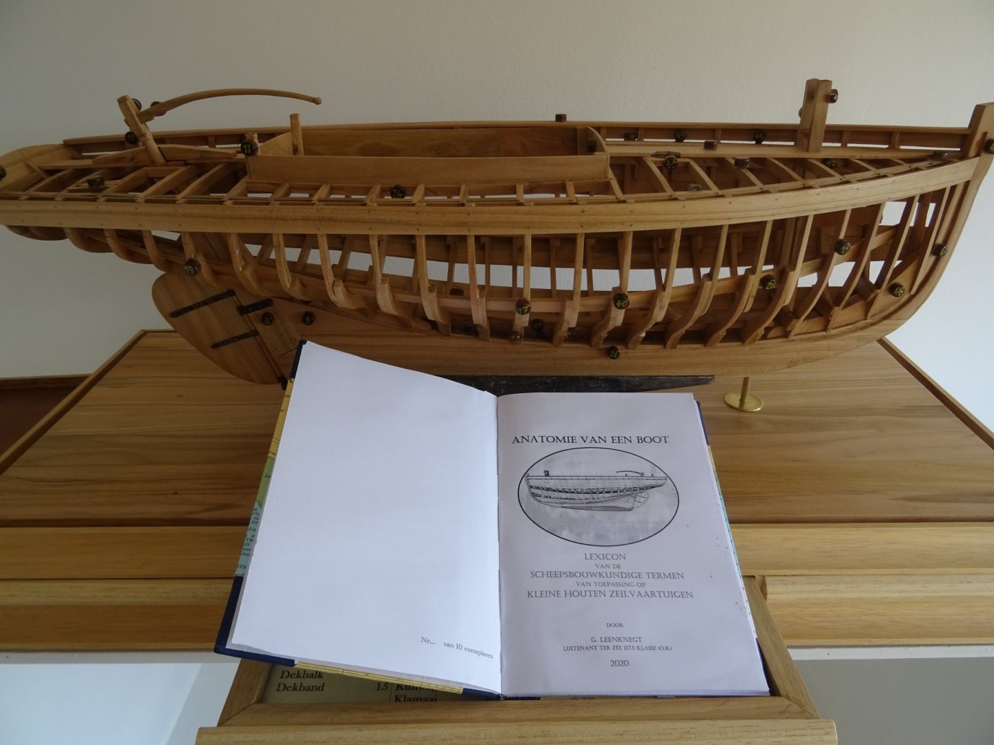
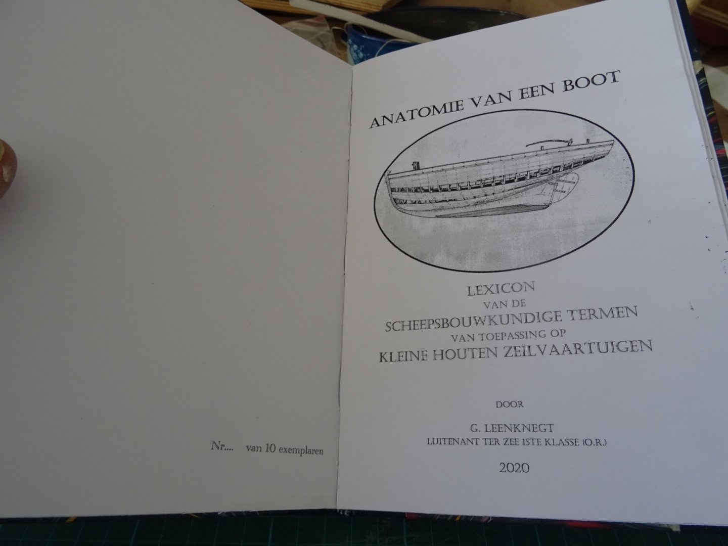
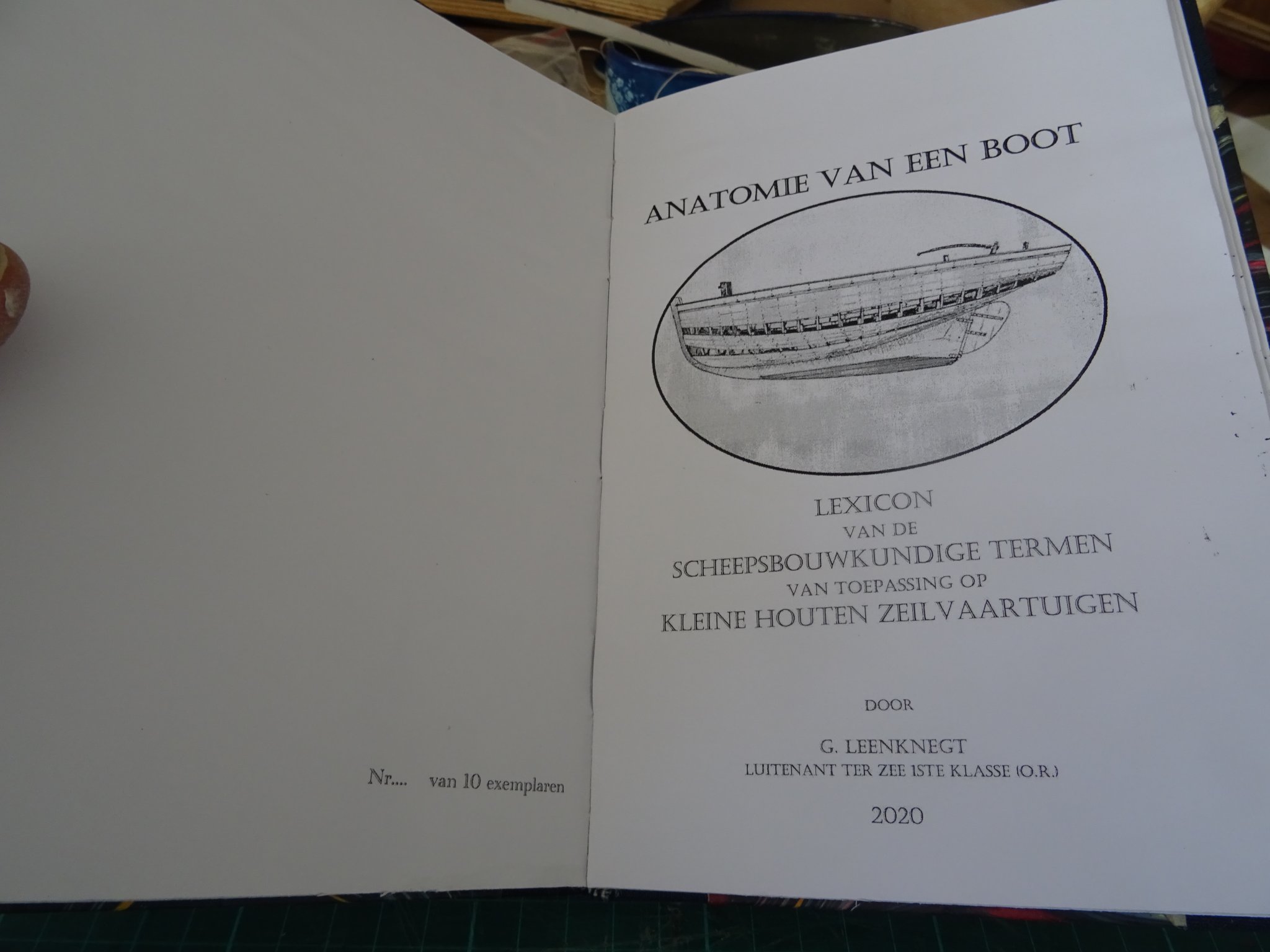
A quick look inside the Encyclopedia.
The title page:
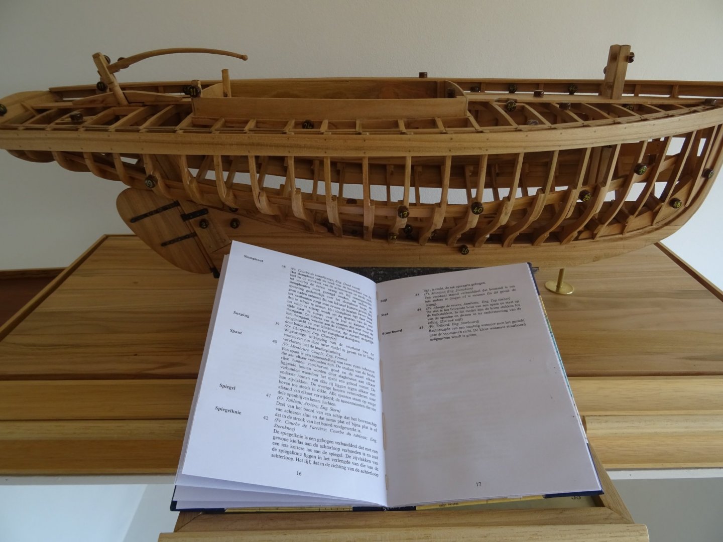
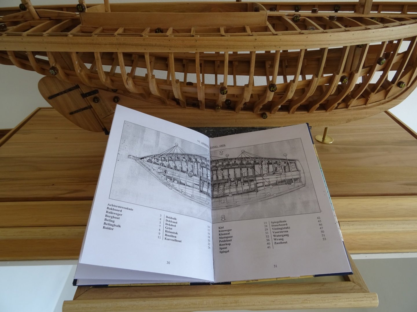
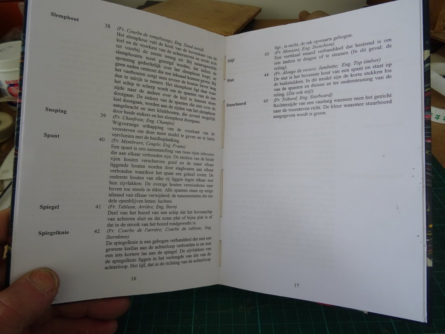
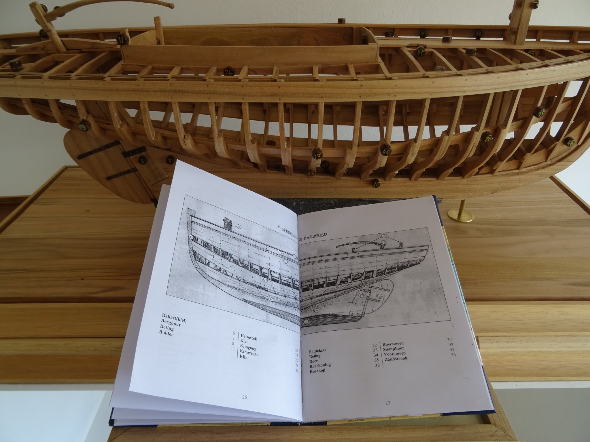
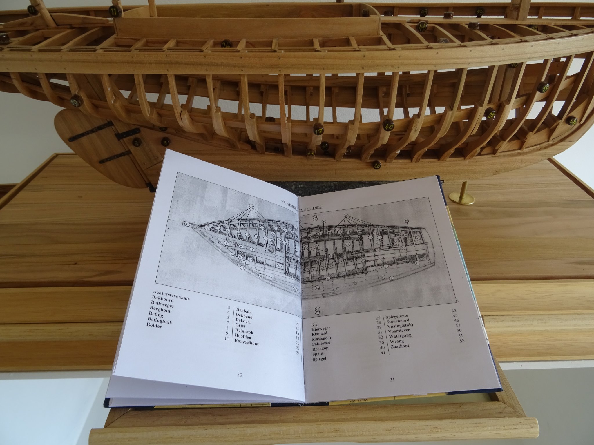
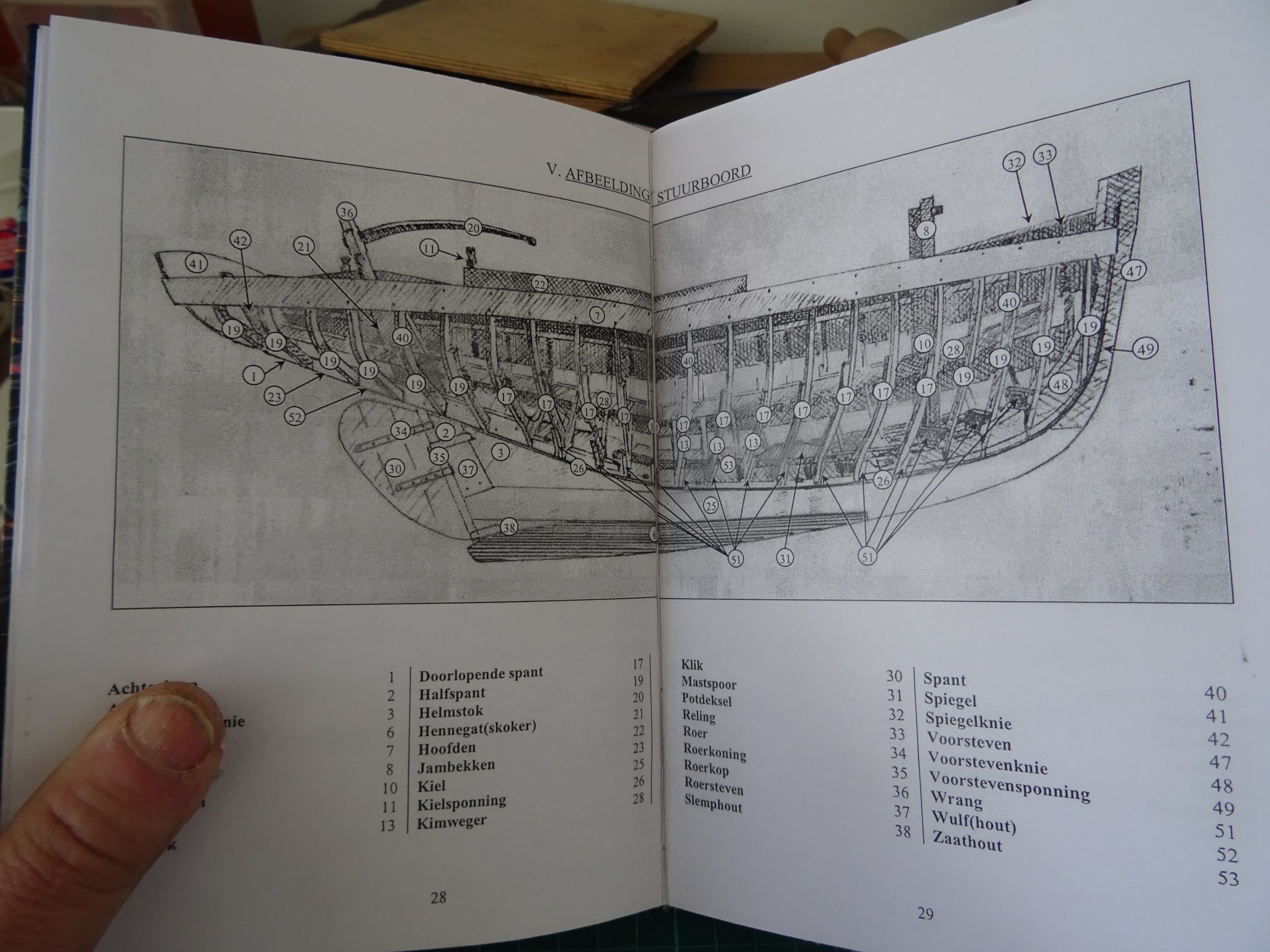
A page of the lexicon:
The translation list French - Dutch - English. There is also a translation list English - Dutch - French.
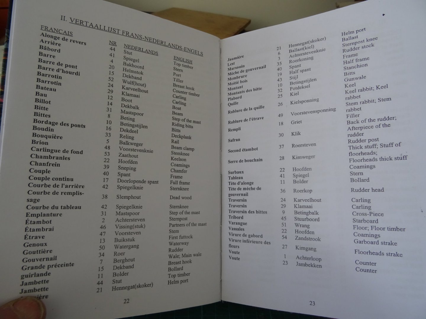
And there are also four double pages with illustrations. They make it possible to use the booklet without the model.

-
-
-
Congratulations on finishing this scene, Yves. It looks like you're getting close to the end result now.
- thibaultron, Canute, yvesvidal and 2 others
-
 5
5
-
-
-
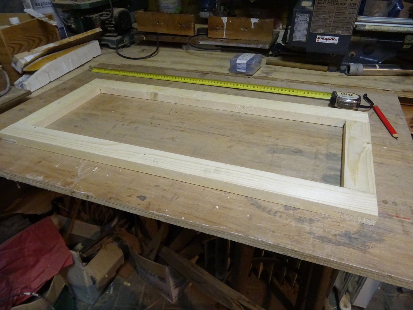
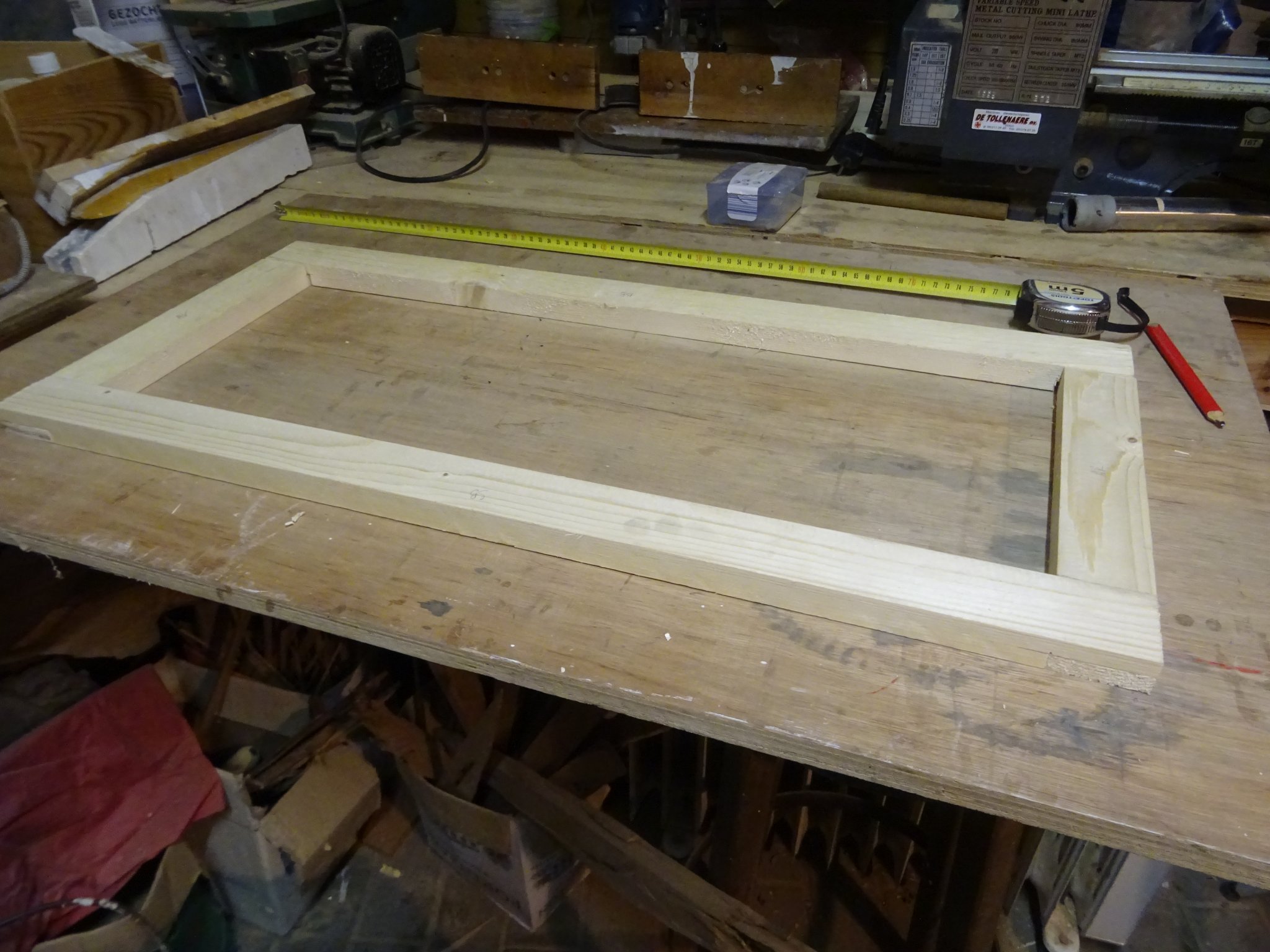
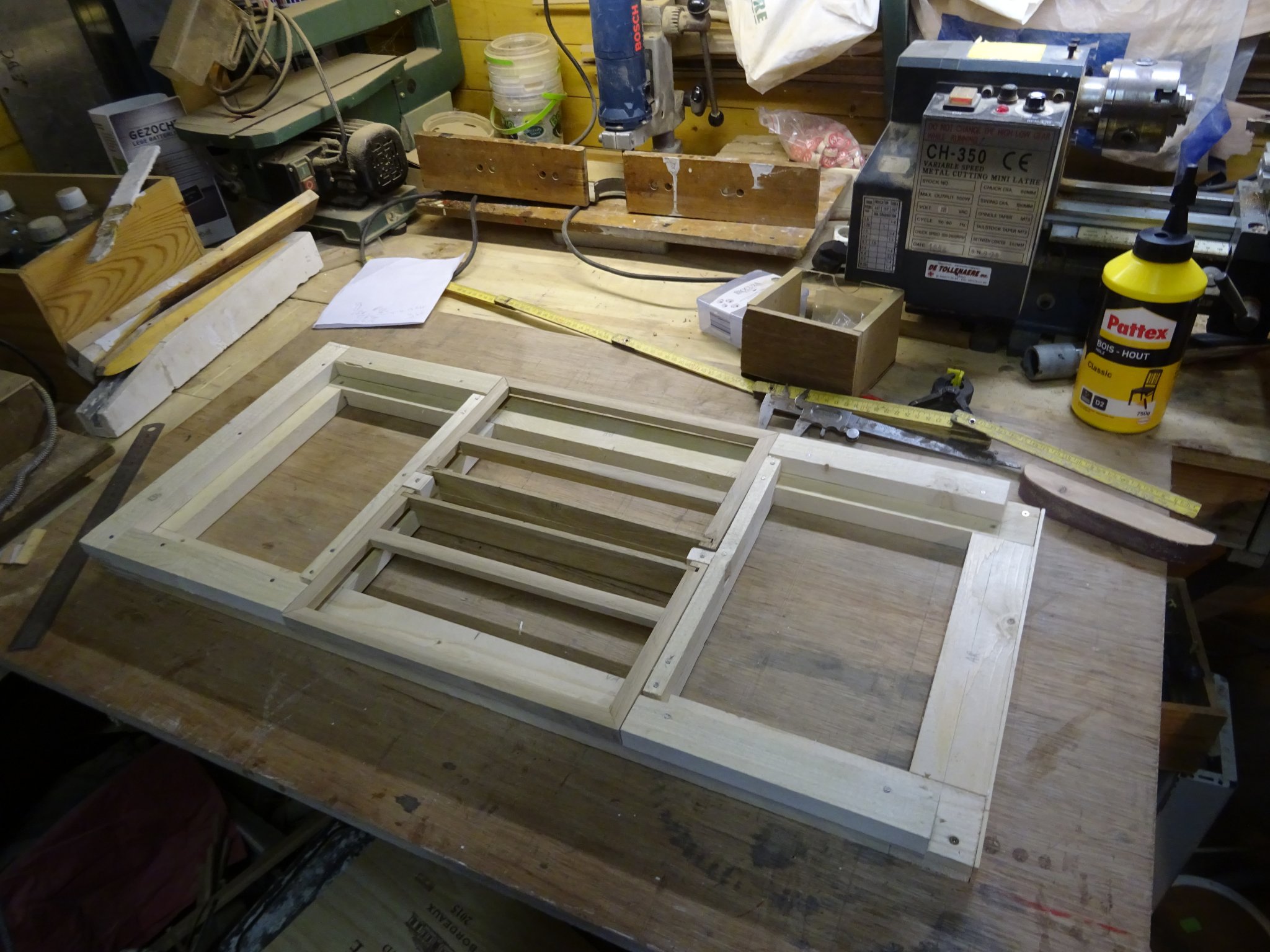
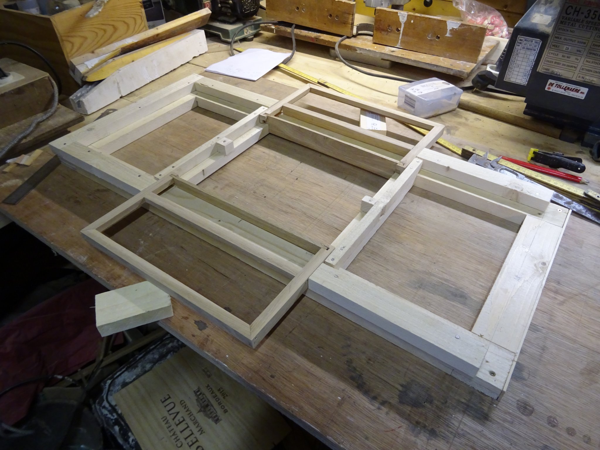
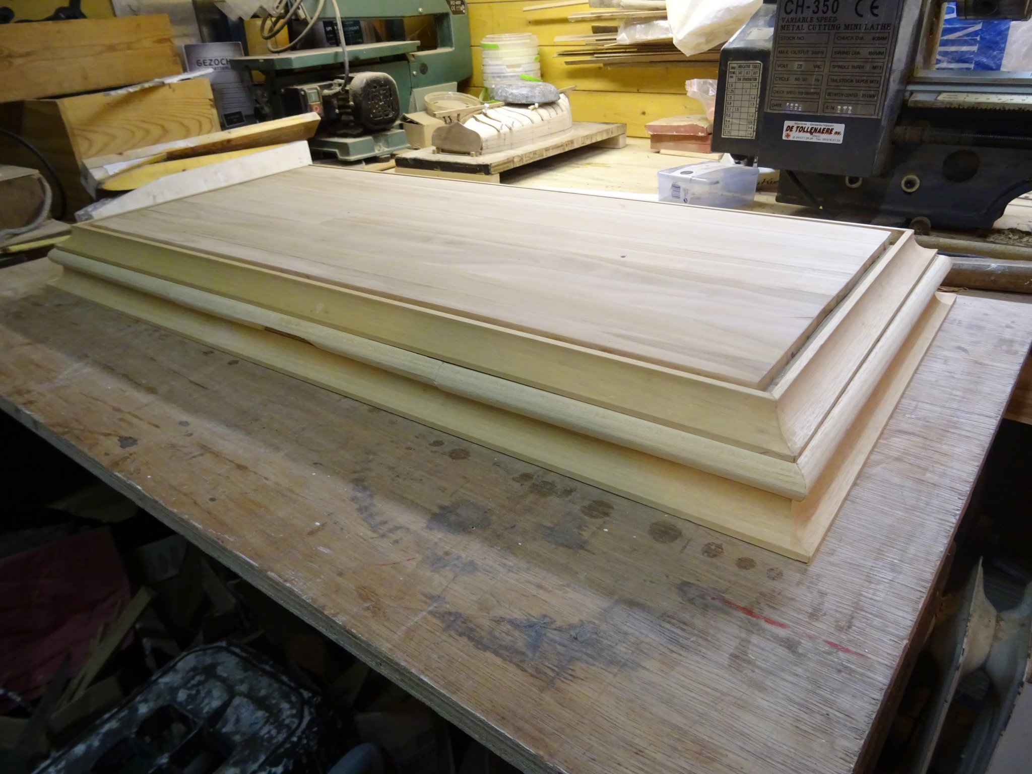
The base for my drawers is a deal frame.
On that base I build two drawers. Here you see them in closed condition.
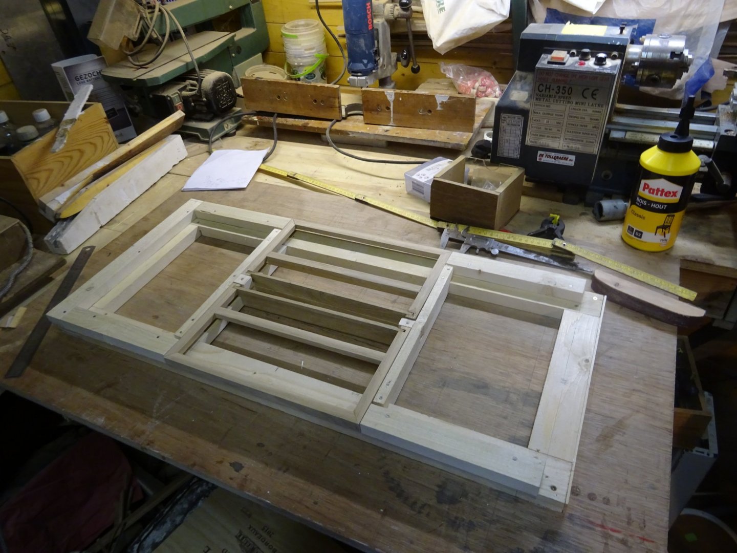
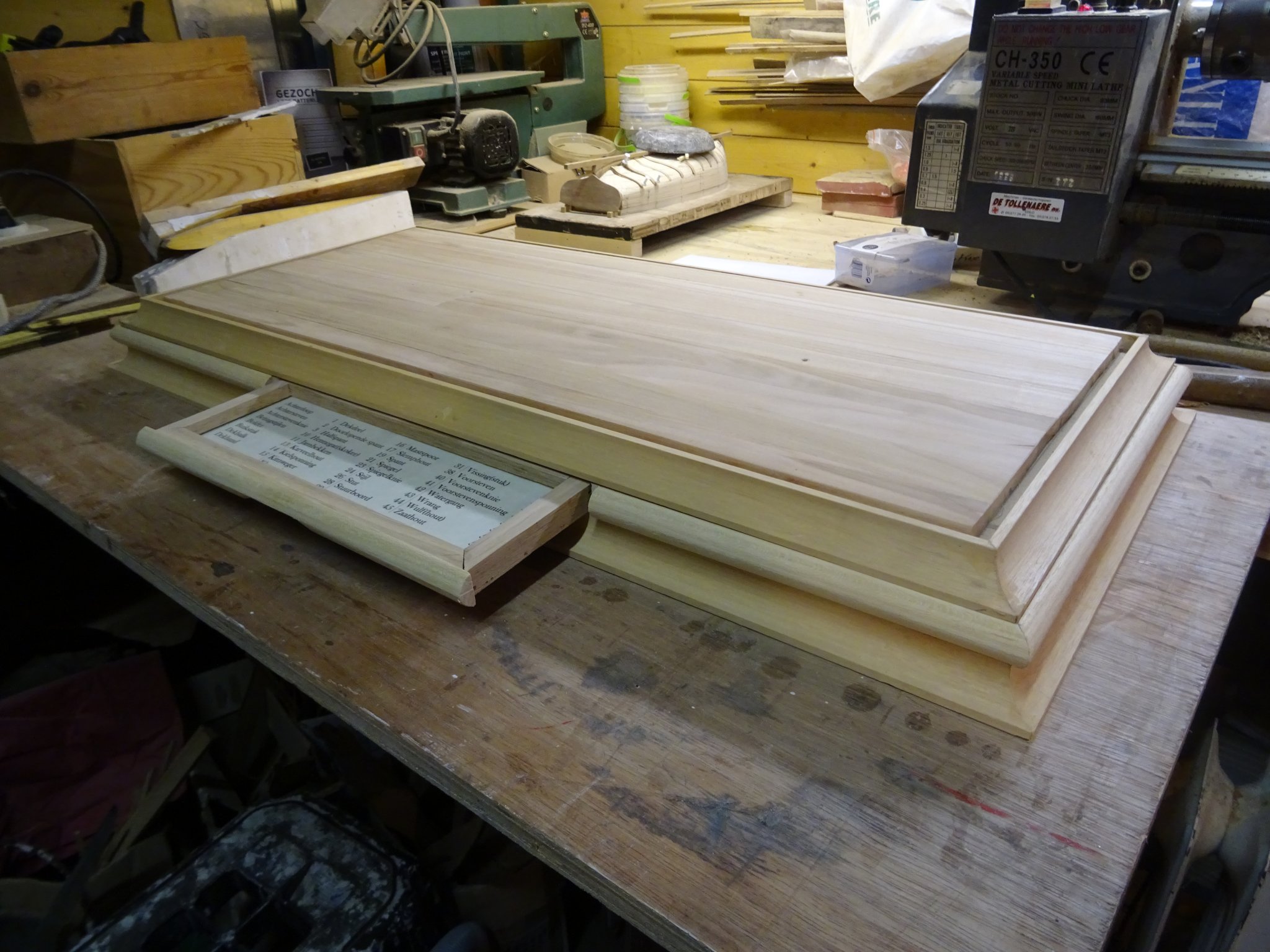
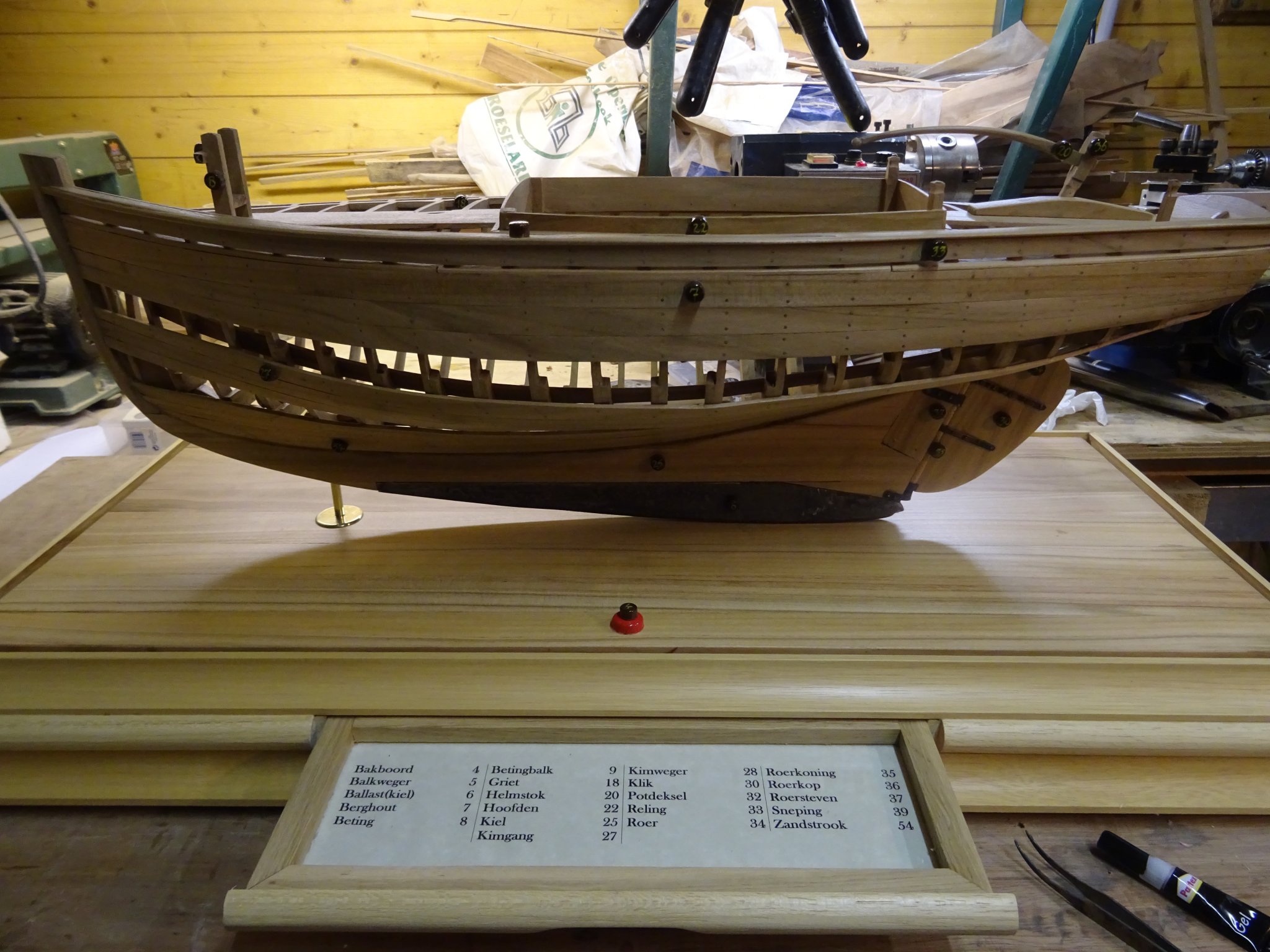
And here they are open. A stop plank at the inside prevents it from being pulled out completely. The right side of the frame is still open. There is space for a third drawer, but that is for the next chapter.

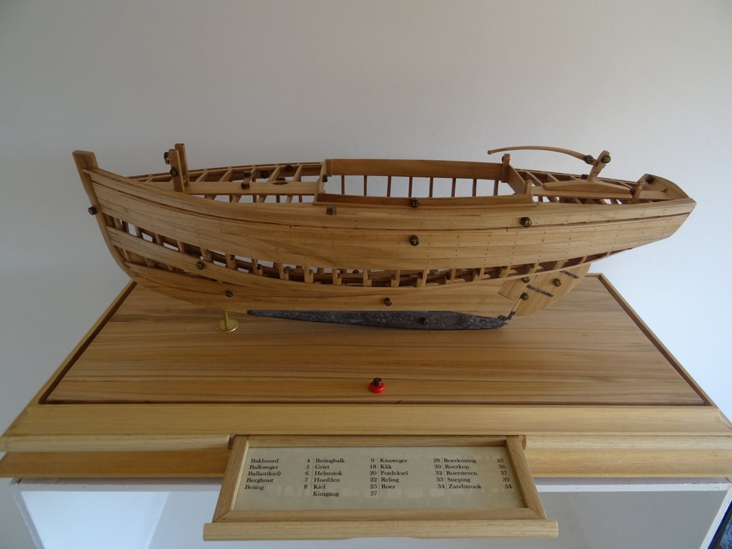
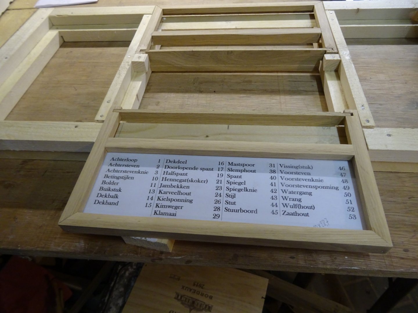
Here is the starboard drawer with a copy of the glossary list in it. The final lists will be printed on more retro looking paper and they will be covered by glass.
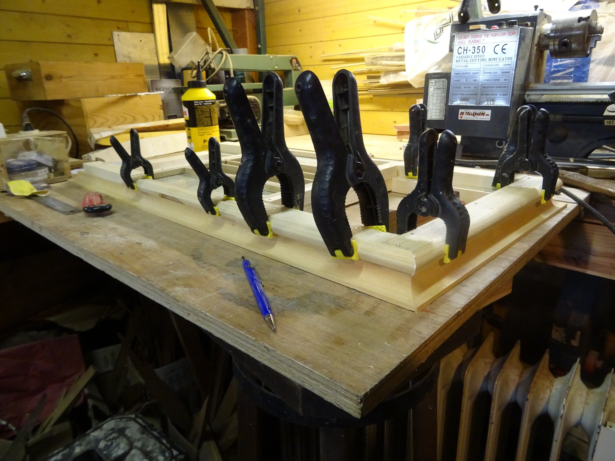
Now the pine frame has to be hidden by a round frame. I make that frame by gluing two quarter rounds together to a half round.
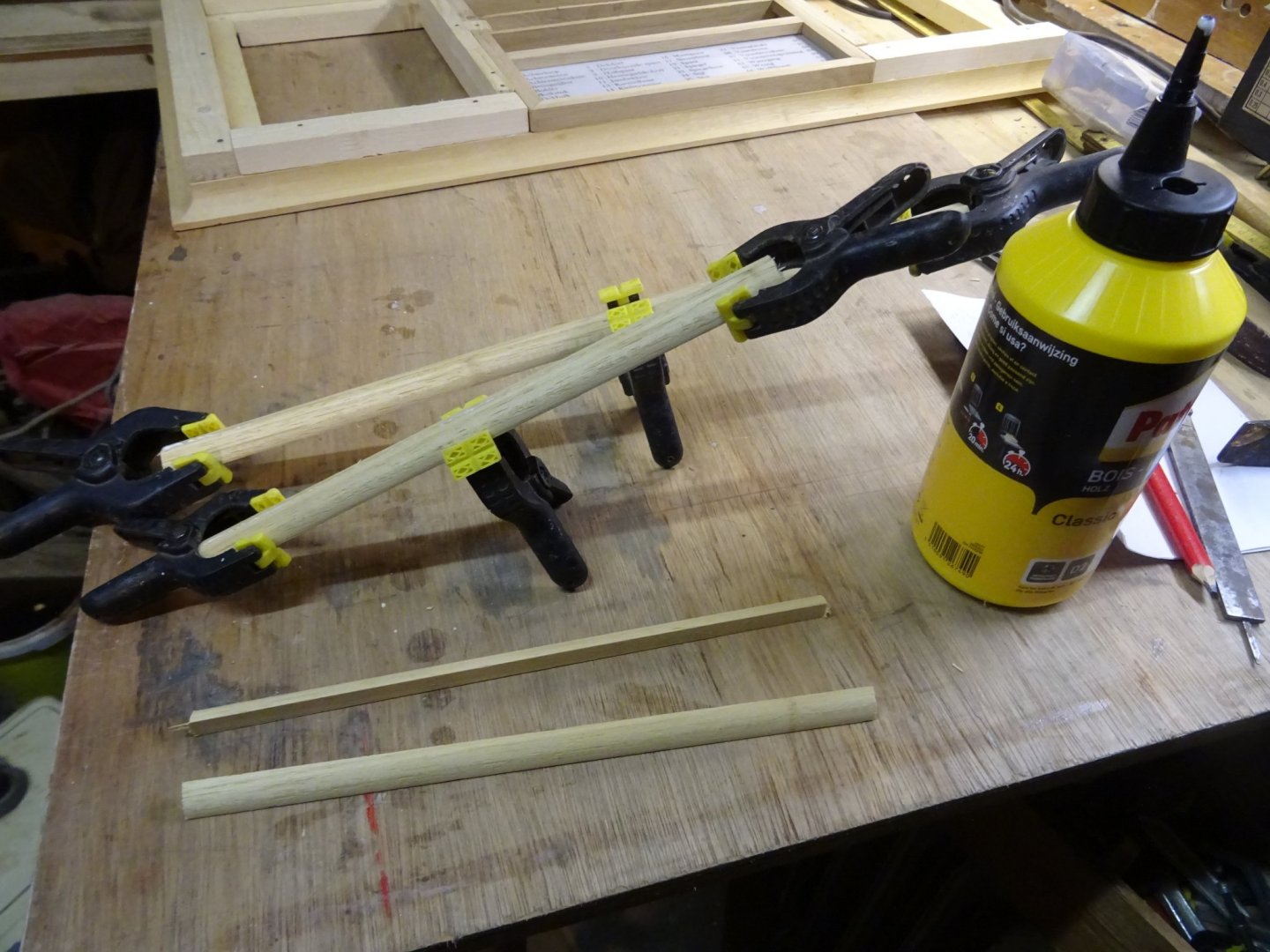
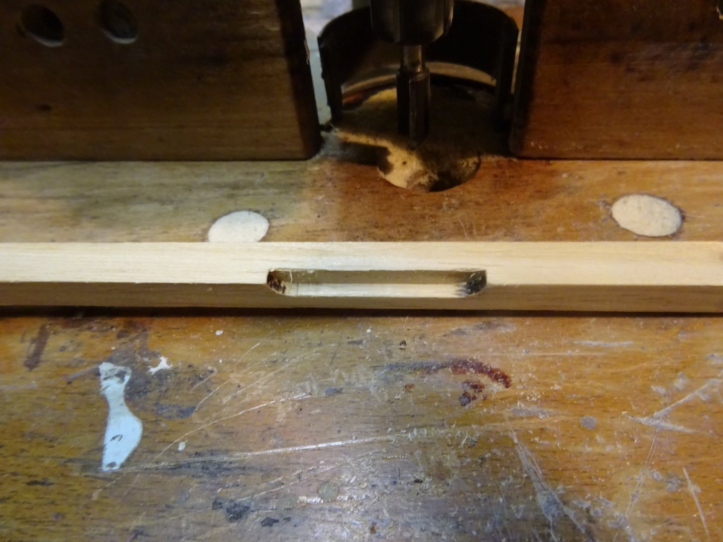
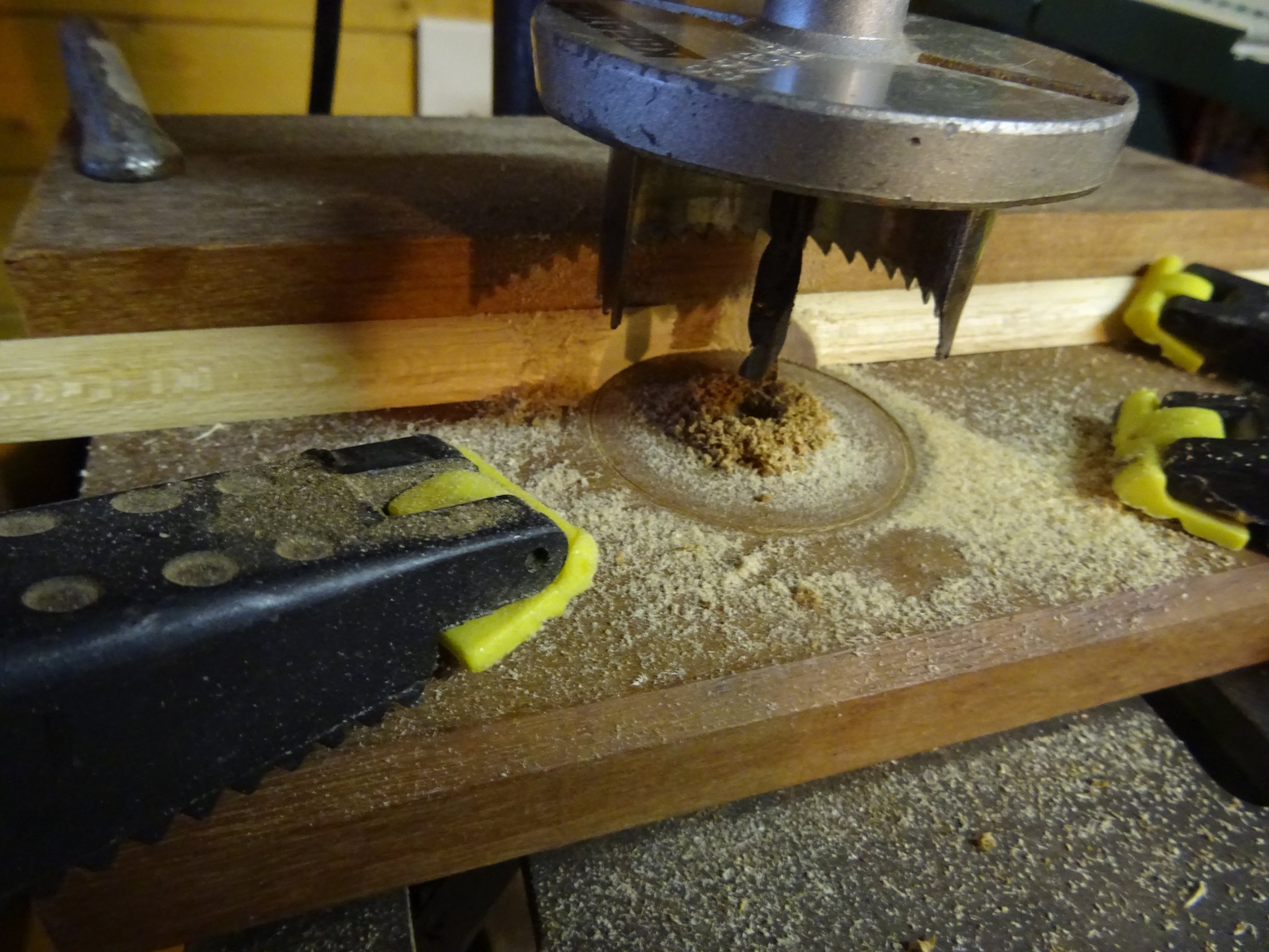
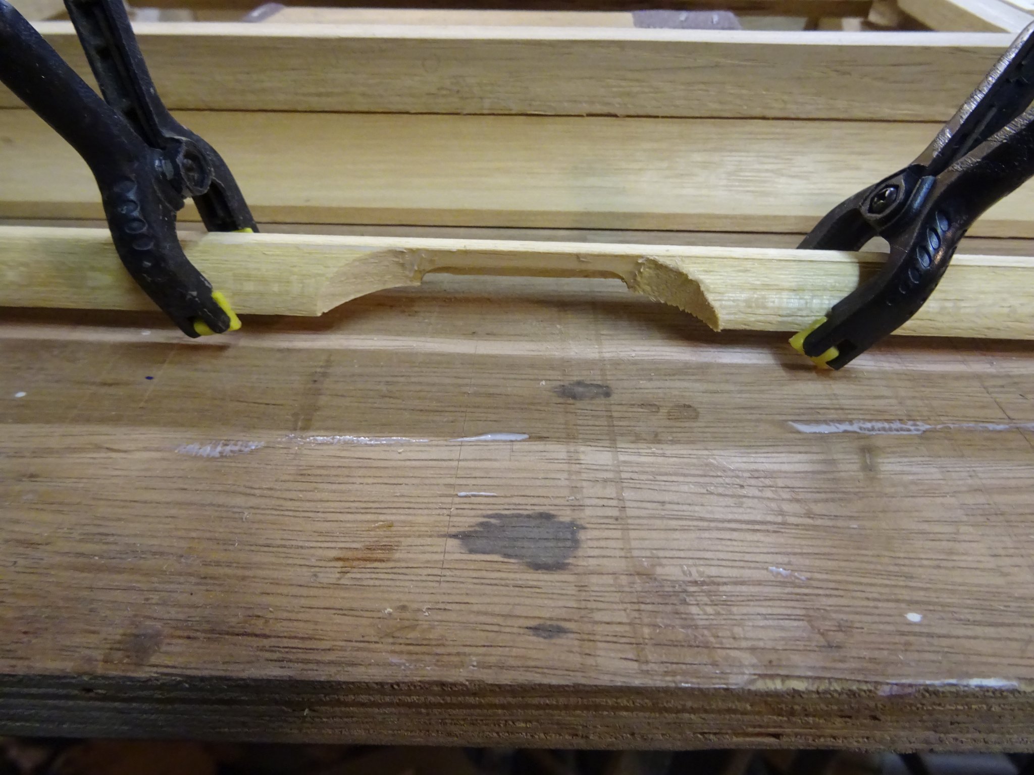
For the drawers, I mill a groove in the upper quarter round before gluing it.
The lower quarter is sawn/drilled in half with a drill clock to have a half round cut.

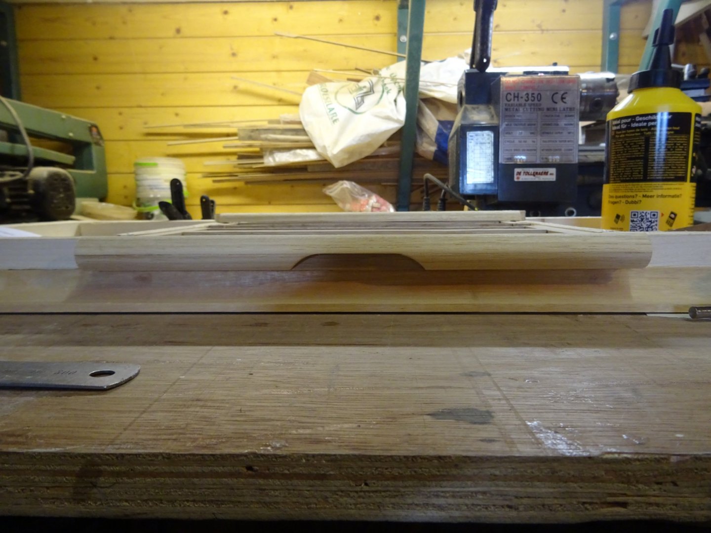
Then it is glued together to a half round frame.

And that is how it looks on the drawer:
Gluing the round frames around the display board.

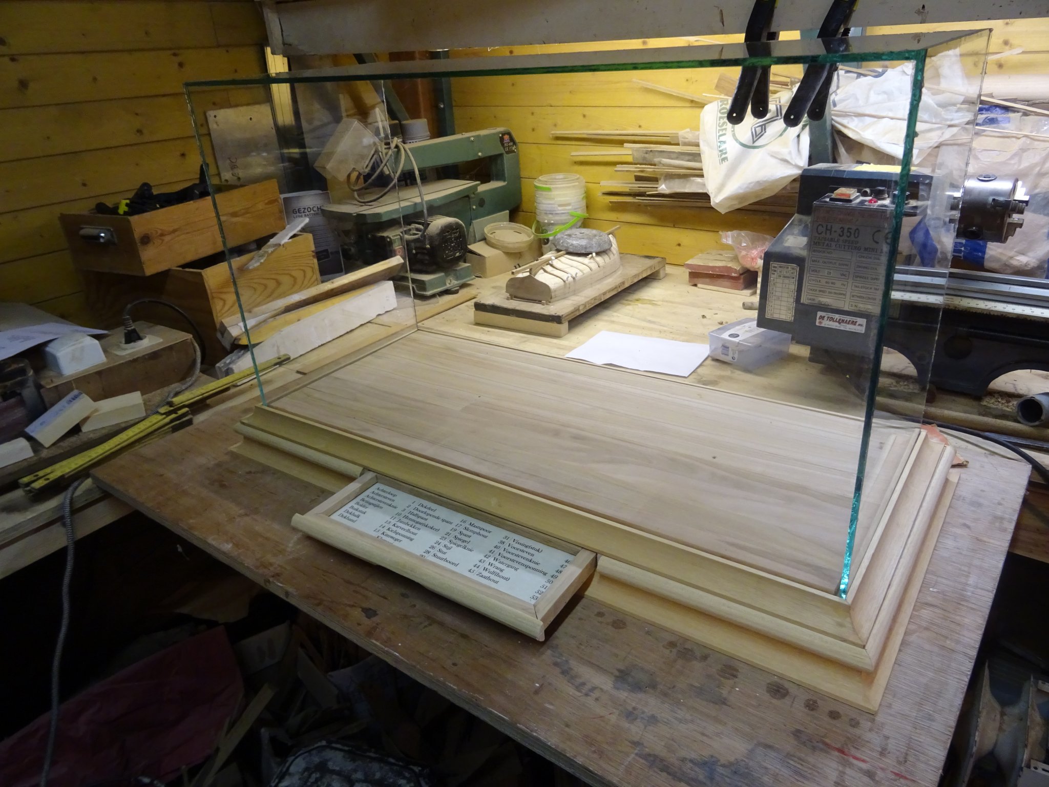
That is how it looks with the drawer closed ...

... and open ...

... and with the dust case.

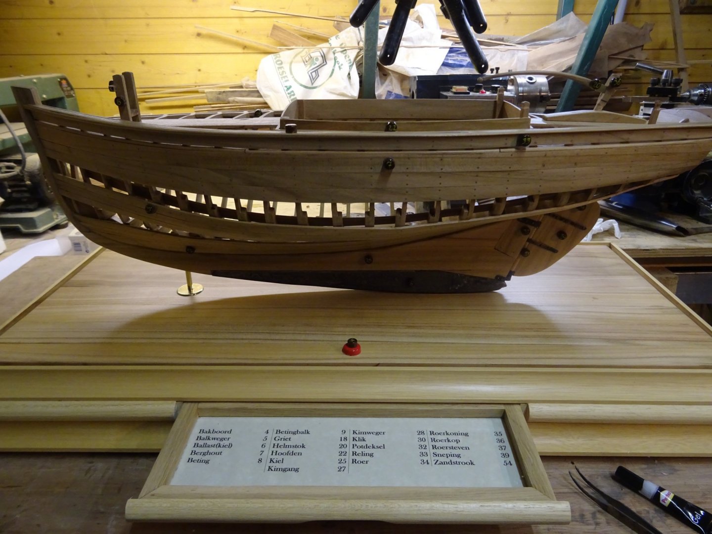
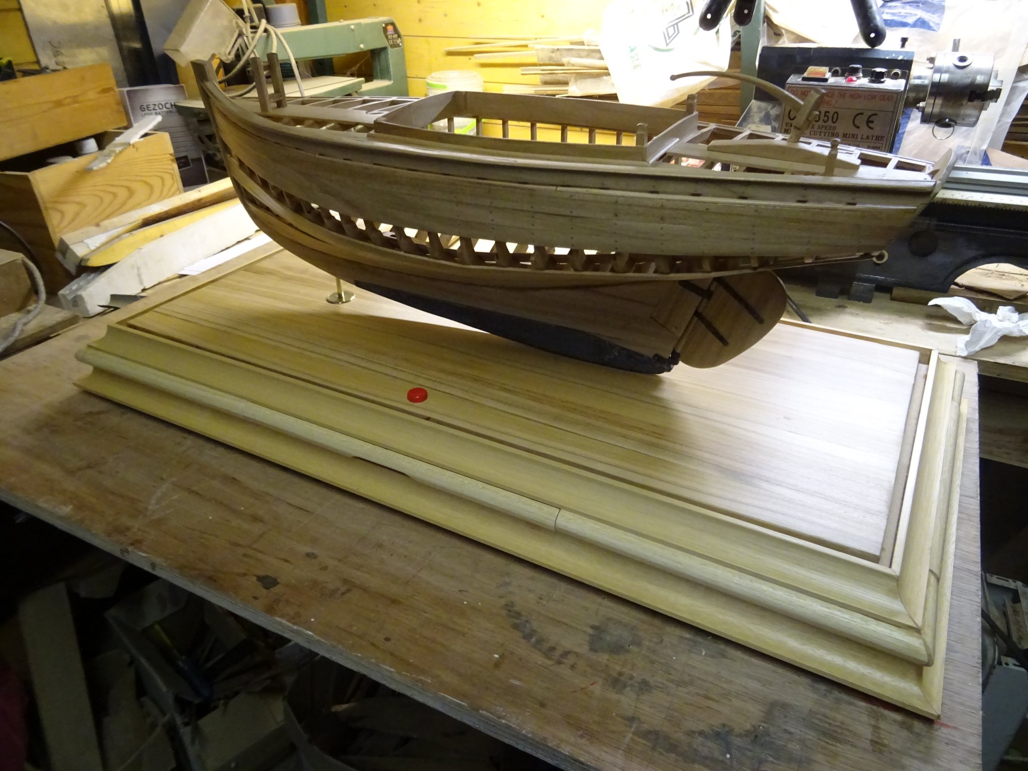
Here with the model on it.

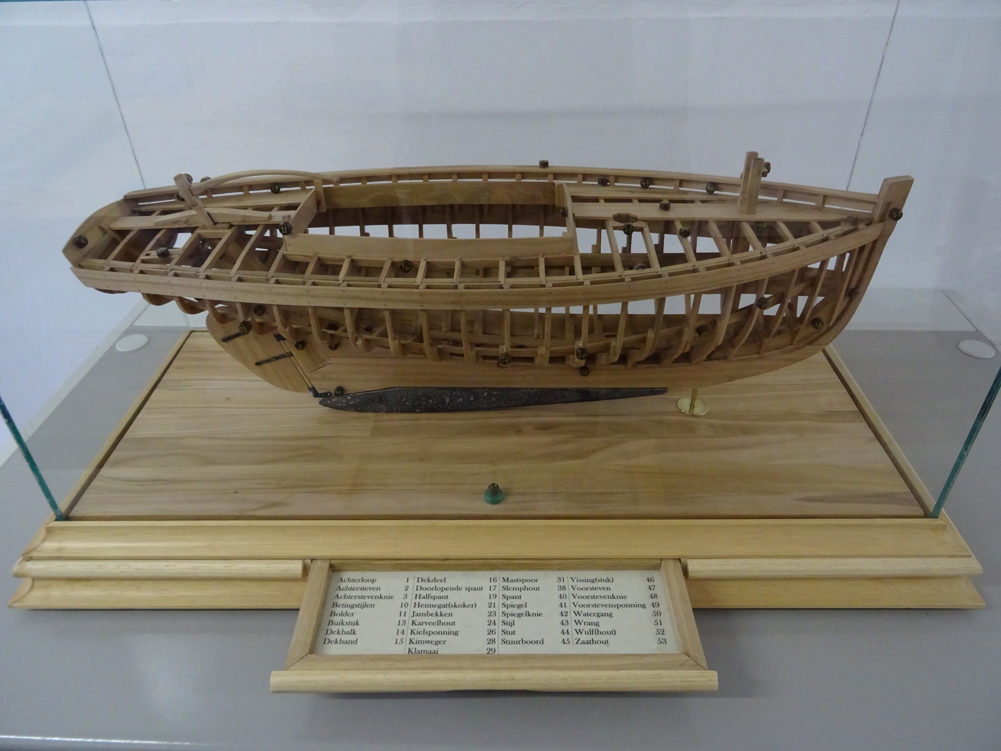
The small brown buttons on the model are the numbers that indicate the different parts which are named in the glossary. In the front, in the middle, you see a red button. At the other side of the board is an equal green button. They indicate the port- and starboard side of the boat. I consider those two also as two important parts of the boat which should to be known by every aspirant sailor or boat builder.
Next week I will deal with the third and final chapter of this build: The encyclopedia.
Thank you for reading
Thank you to follow
Thank you for the likes
and thank you for your constructive comments,
Till next week and keep it healthy!
-
On 4/14/2020 at 9:36 PM, Barbossa said:
Hi G.L. : Thanks for the immediate answer, much appreciated.
The reason of my inquiry : the weight of the display could be an issue for my completed previous build.
Christian, The weight of the case is indeed considerable, but I can carry the whole of model, displayboard and case alone but the size is somewhat unpractical.
-
Beautiful work, Kevin.
- FriedClams and mtaylor
-
2
-
7 hours ago, Mark Pearse said:
Hi Christian
(Geert I hope you don't mind my butting in, but I have some experience in this). I have helped make a few large acrylic (plexiglass) cases. We found that 4.5mm could make a wider case than 6mm; 6 would would start to sag in middle before the 4.5 did.
Now problem, Mark. I would like to learn how to cut and glue plexi myself.
-
What a great difference with the metal rub rails and cutwater at the bow. You are doing a very nice job, Tom.
-
2 hours ago, Barbossa said:
Truly wonderful and inspiring work, G.L.
Can I ask a question about the display case ?
I may have overlooked, but are you using genuine glass or plexi glass ?
In either case how thick are the blades ?
Regarding the plexi variant, I was recommended by a manufacturer a minimal thickness of 6 mm ( provided the length = 1,2 m and 1 m high )
Thank you for the compliment, Christian,
I used real glass for the case, no plexi.
The top and the two side panels are 5mm thick. The front and back panels are 3 mm thick. There is no other reason for the use of two different thicknesses than the availability of the pieces glass of sufficient size. The 5mm glass comes from an old greenhouse that I demolished in the garden. The 3mm glass from old single glass windows from the house of my late mother in law when they have been replaced by double glass windows. I had to use waste glass because the do it your self shops are closed during the Covid-19 measures.
-
-
-
On 4/11/2020 at 4:57 PM, EricWilliamMarshall said:
I have to ask, what’s next?
Eric, I am presently working at the drawers for the glossary lists which will be integrated in the presentation board. Next Saturday I will report the progress on that.
-
9 hours ago, KeithAug said:
Geert,
I liked the work ol the rudder, the sweep of the tiller is particularly attractive. I thought your numbers were finely done, not many would have gone to the trouble. What did you use to glue the glass together.
Thanks Keith.
I used TEC 7 transparant construction glue.
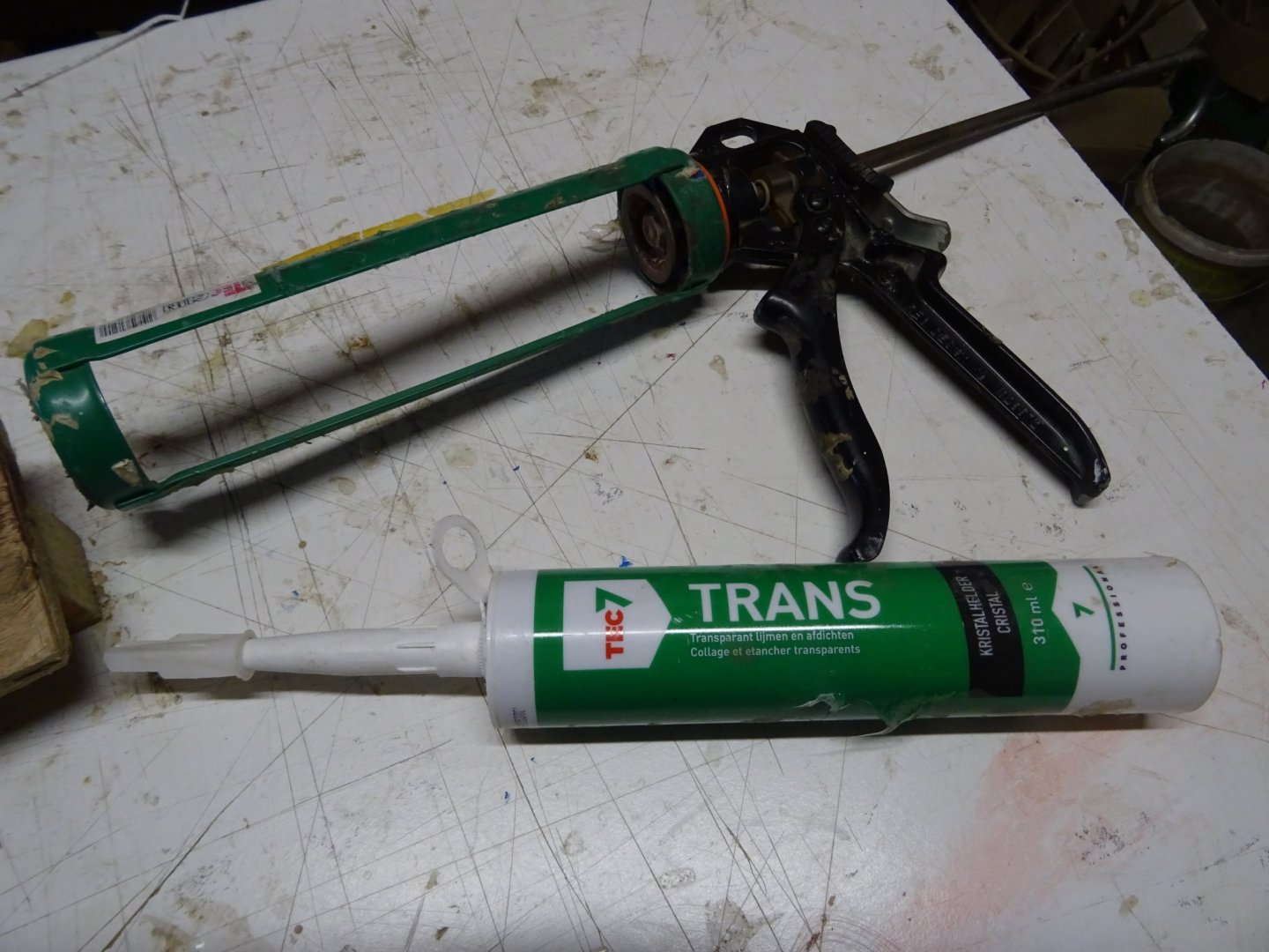
If you look very close to my glass case, you see that it is not a professionally made one, but it is good for its purpose: to protect the model from dust. If ever needed, a professionally made case can always been ordered.
- EricWilliamMarshall, mtaylor, druxey and 1 other
-
4
-
-
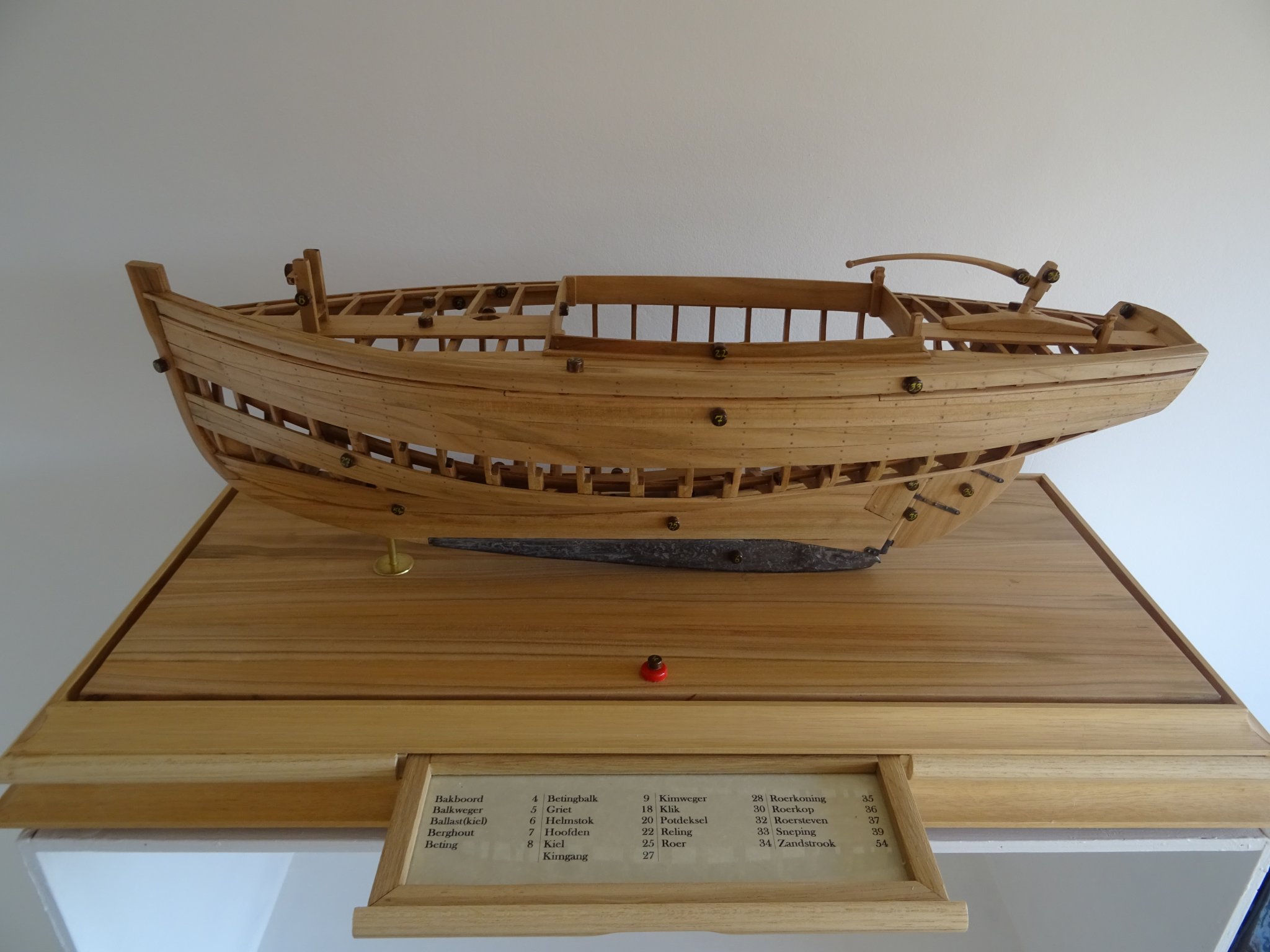
2. The glossary
There will be two glossary lists for this instruction model, one for the starboard (open) side of the model and one for the port (closed) side. My original thought was to place them on the display board at both sides of the model.
One of you, my colleague modelers, gave me a better idea. In his log on the pound naval cannon Allan O'Neil made a display board with an drawer integrated which held the engraved information plate.
Allan, I don't know if you are following my project, but I am grateful to you for your idea!
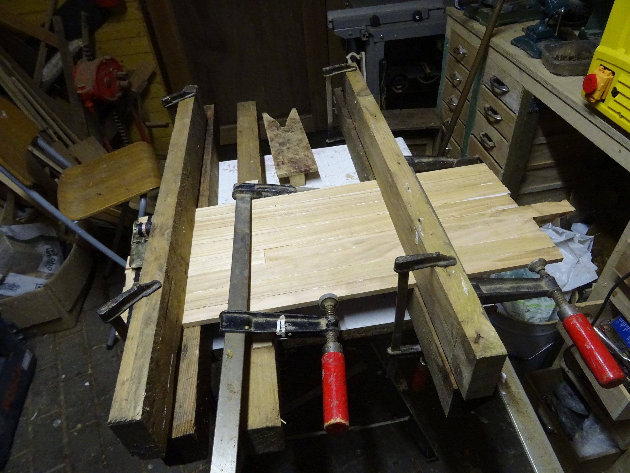
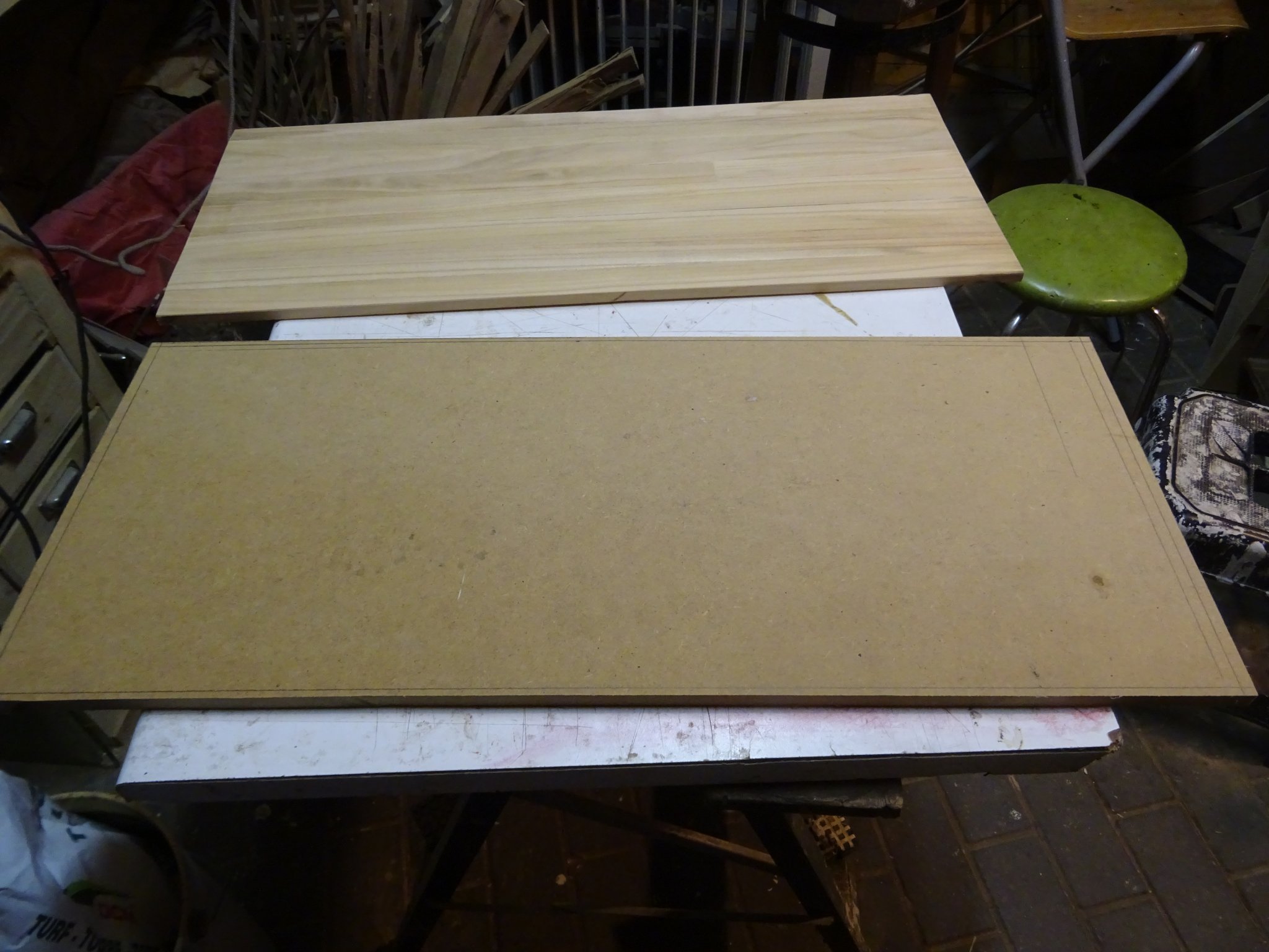
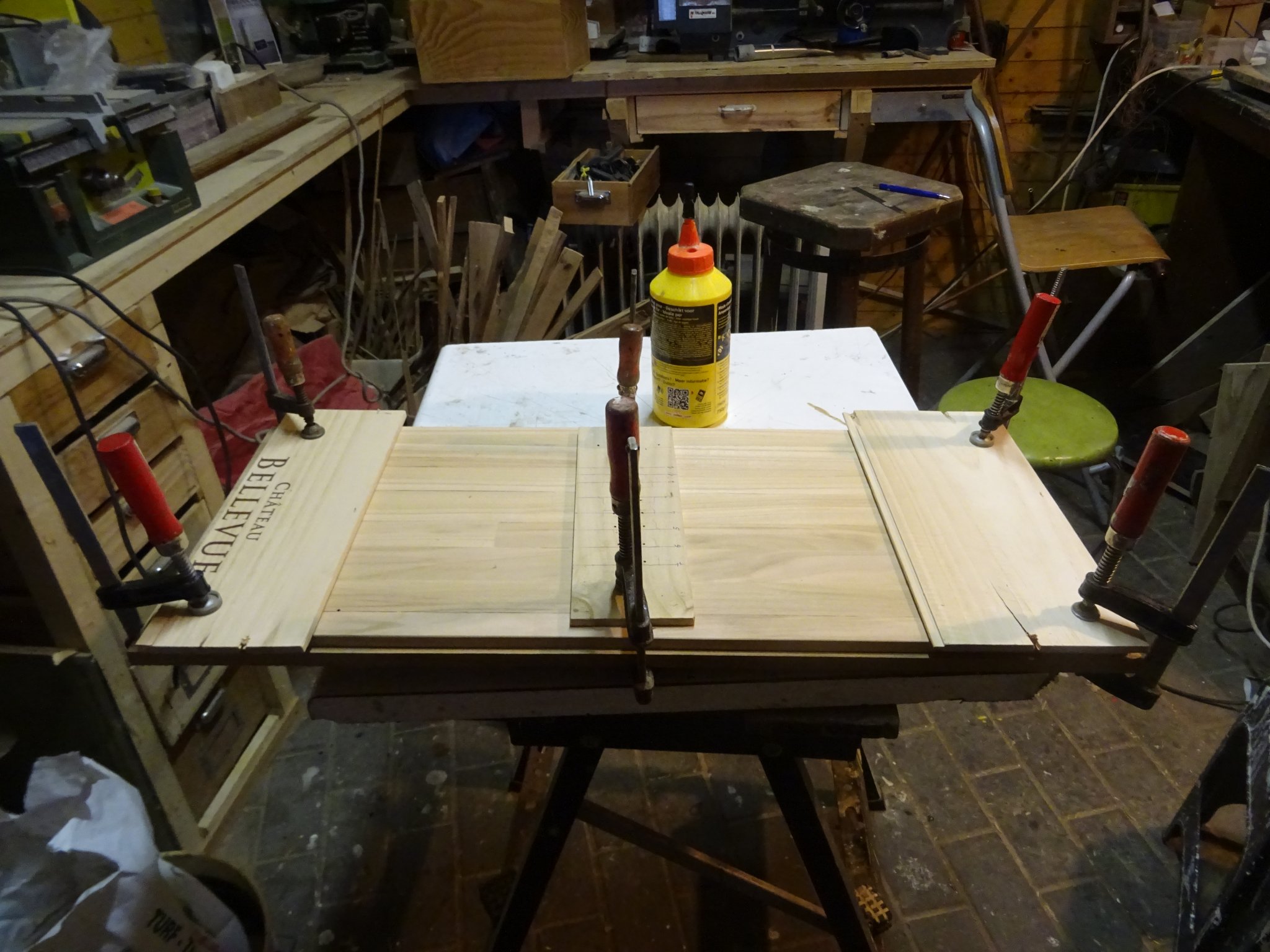
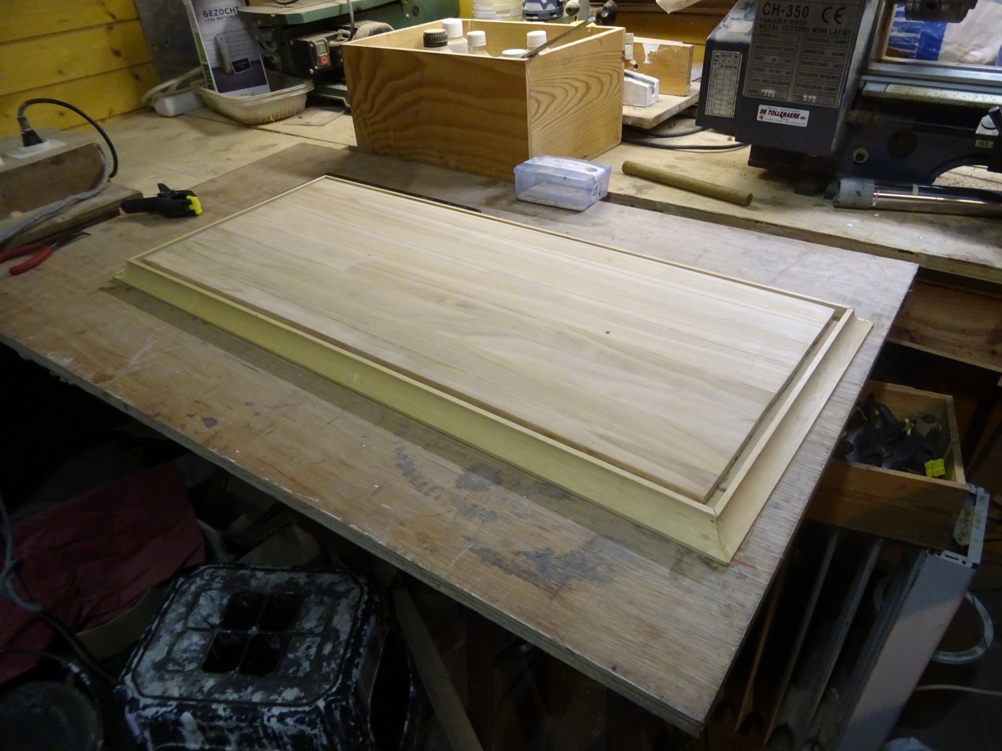
I will make an display board with at each side a drawer in which will placed the glossary lists. If you want to know what's the name of a part on the model, you just have to open the drawer and look for the number.I start with making the top layer of the display board. Just like the model it will be made of cherry. I have no tools to saw very wide planks; my board has to be composed of a series of narrow cherry planks. After they are sawn an planed to thickness, I glue them together.
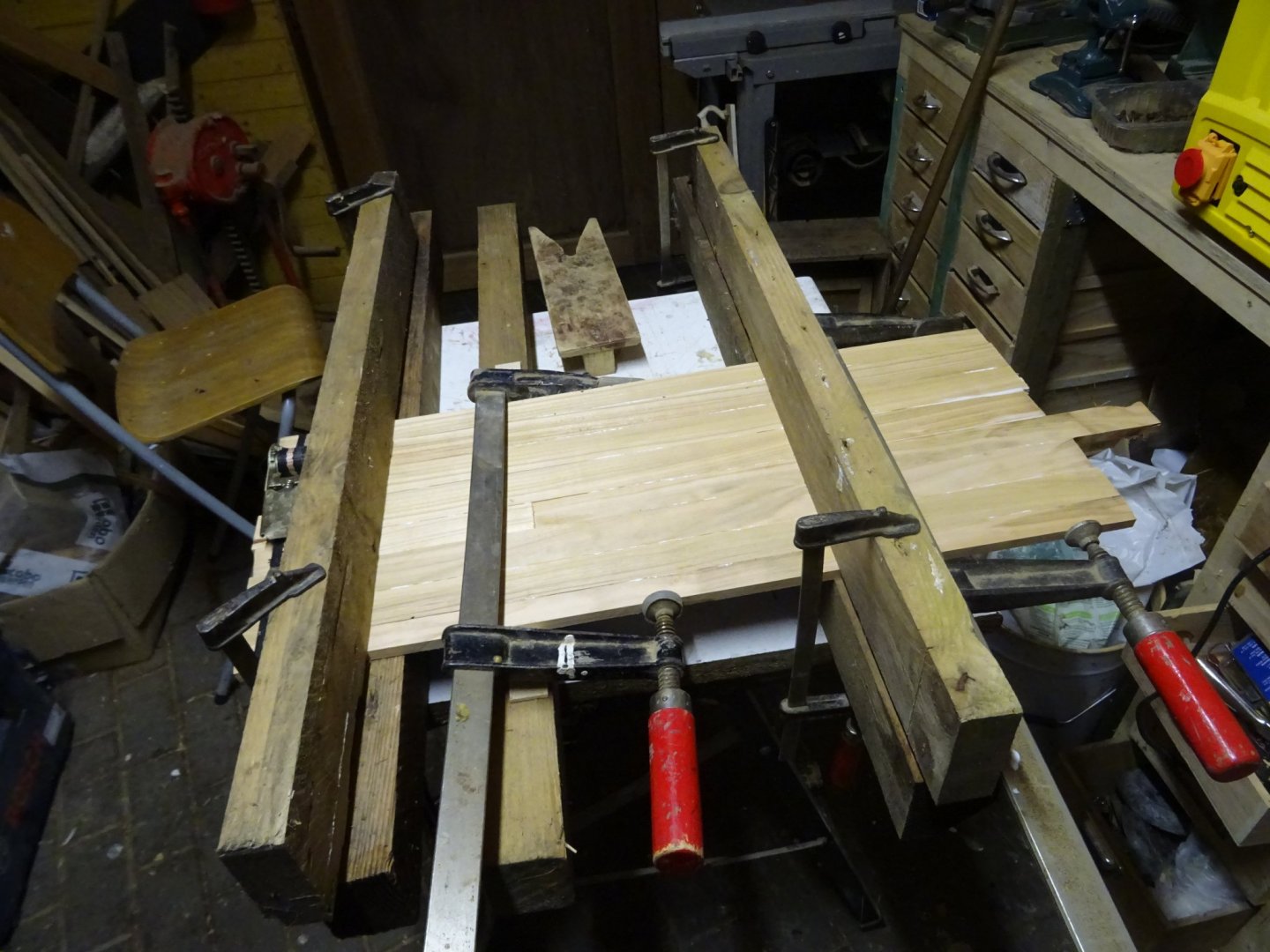
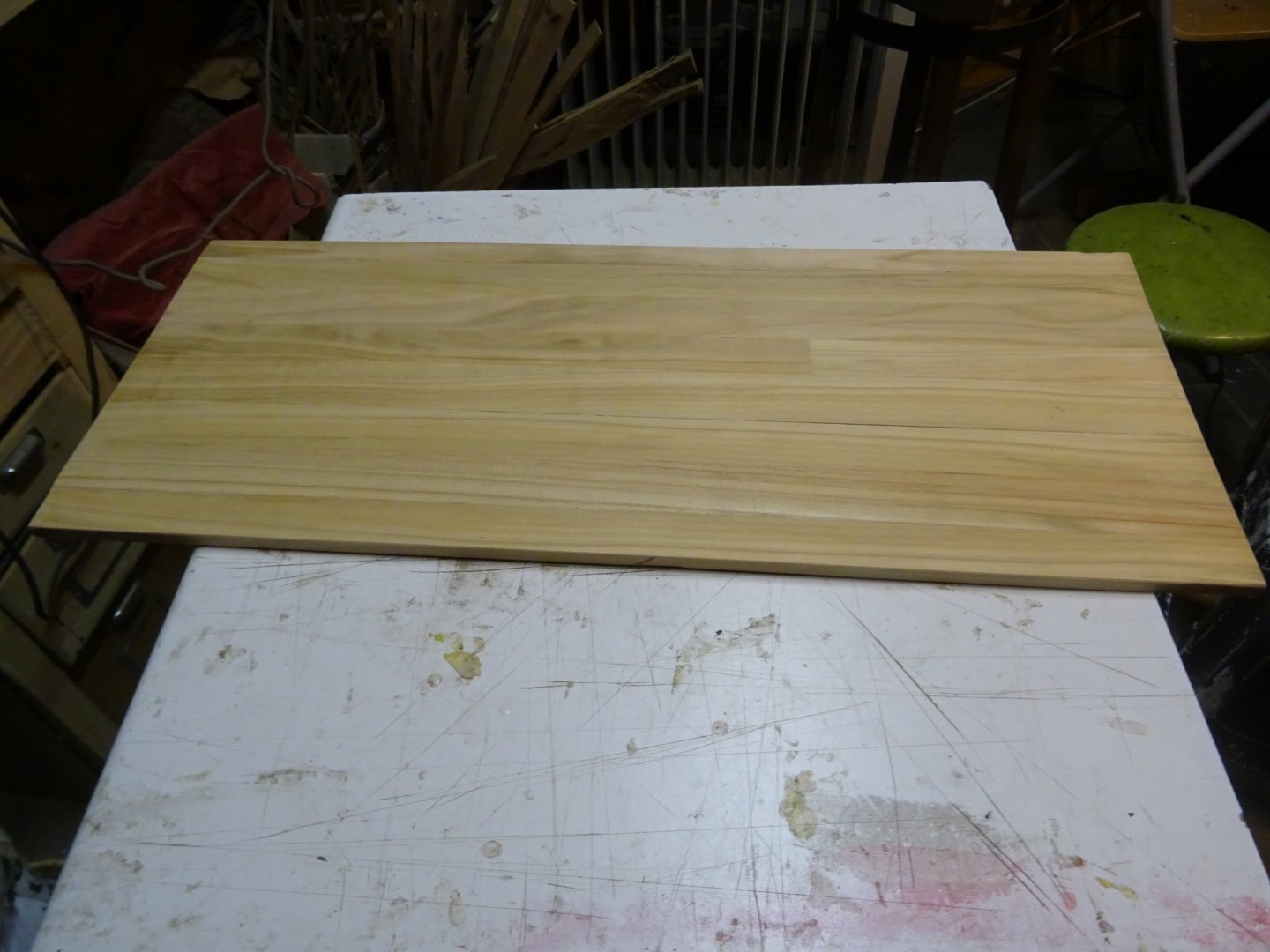
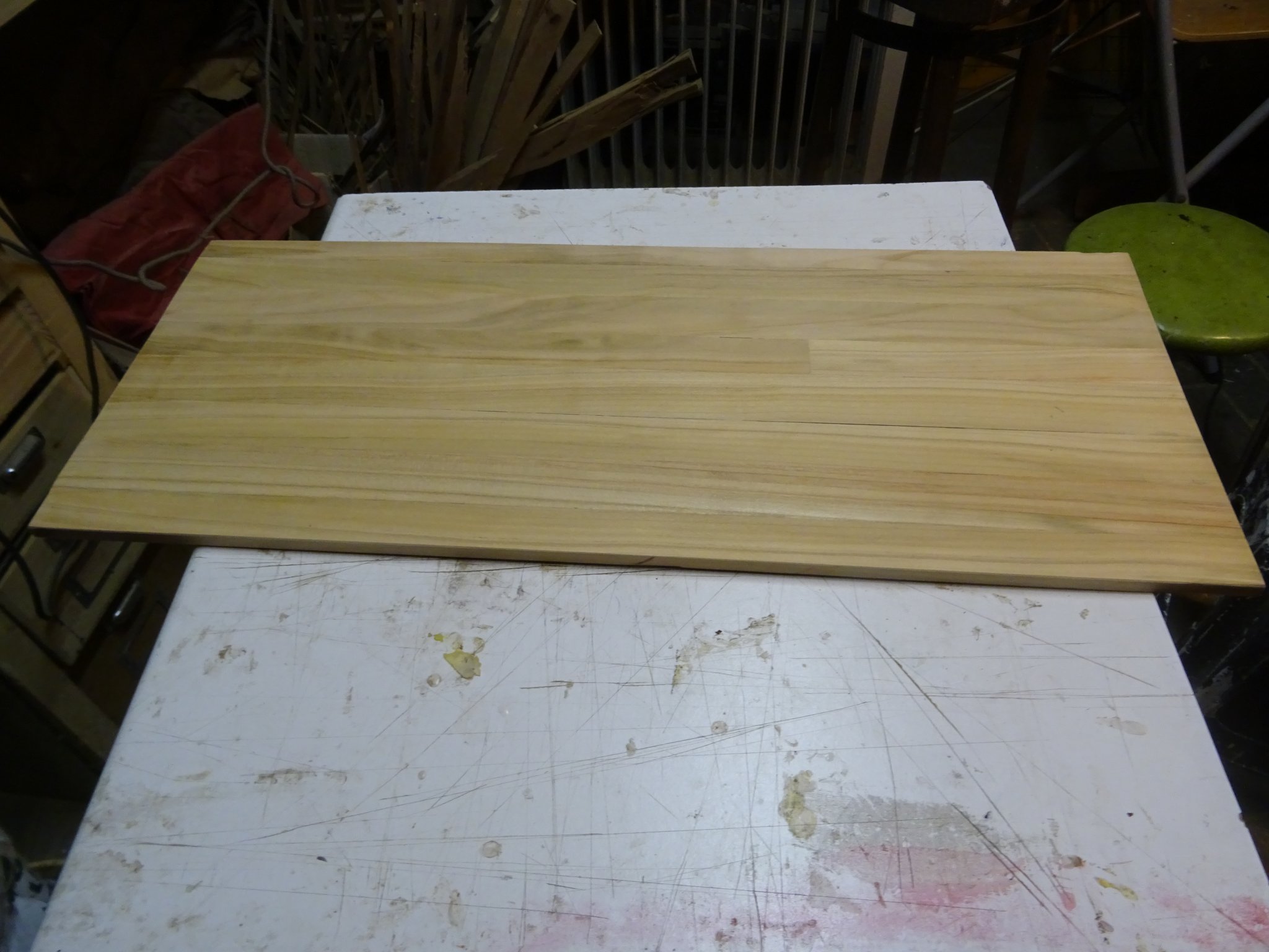
The board, sawn to the right dimensions and sanded.
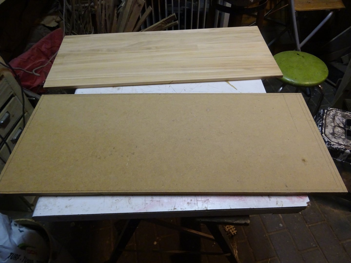
The board will be glued on top of an MDF board.

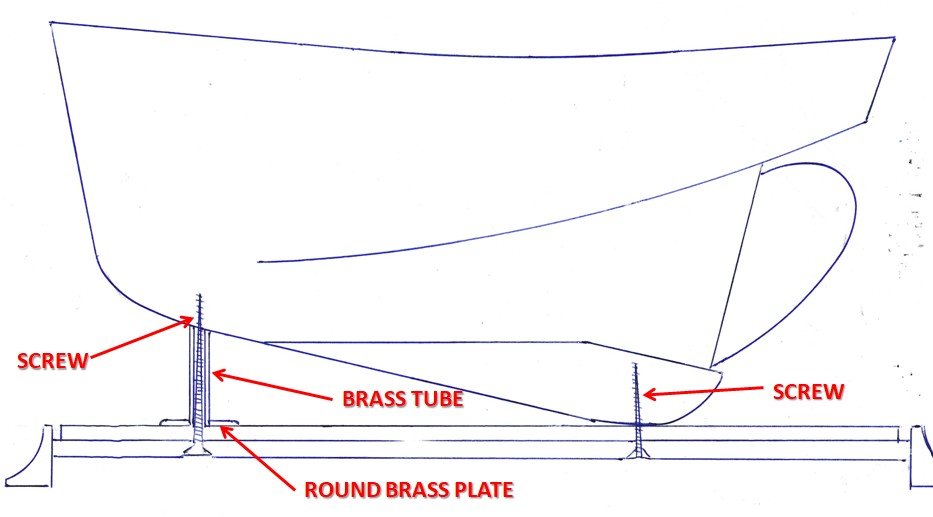
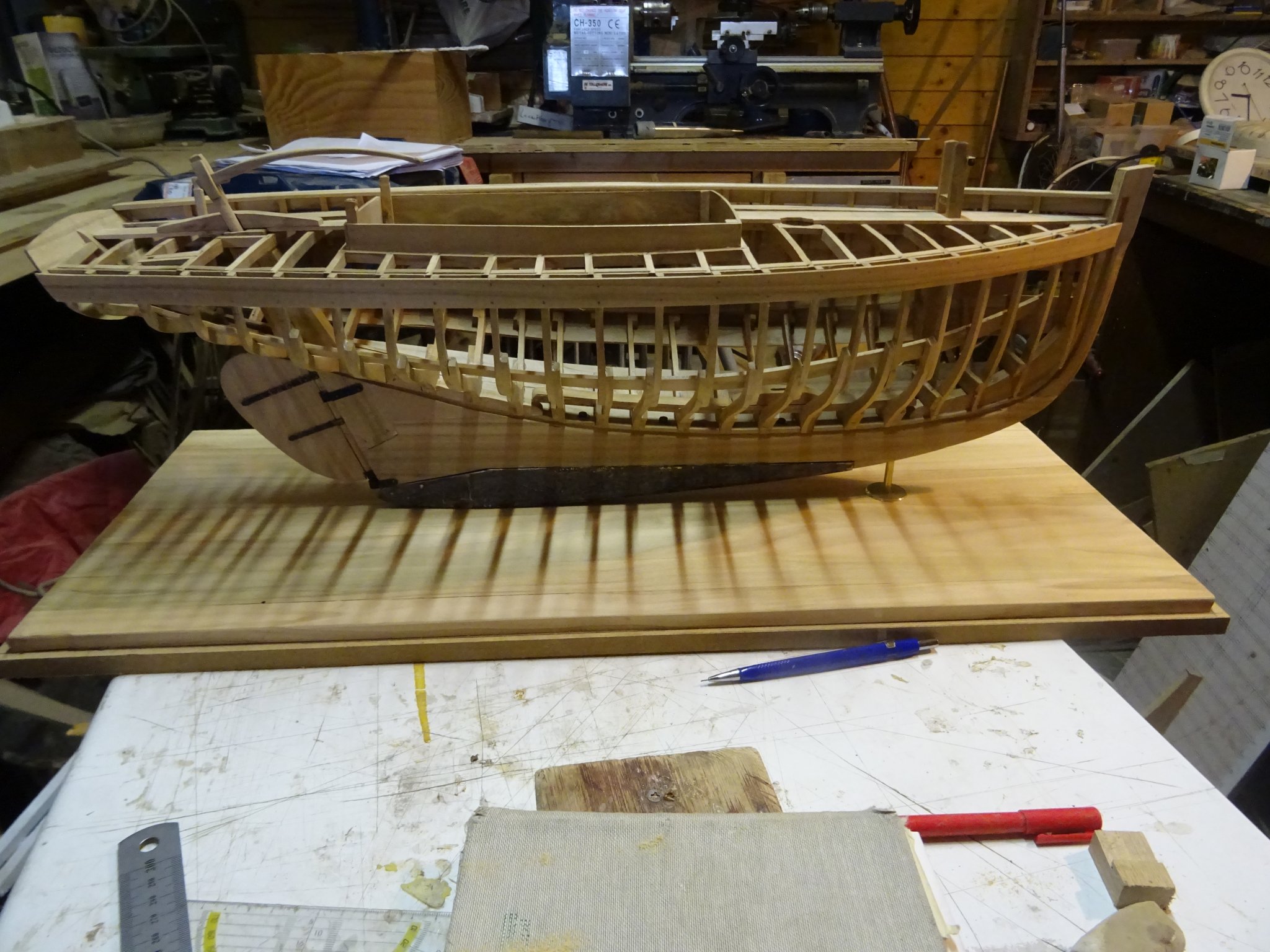
I prepare the placement of the model. It will be fixed on the board be two long screws The ballast keel touches the display board, but because of the steering load the front of the keel hangs about three cm above the board. I will let it rest on a brass tube of 3 cm long through which goes the screw (sketch not on scale).
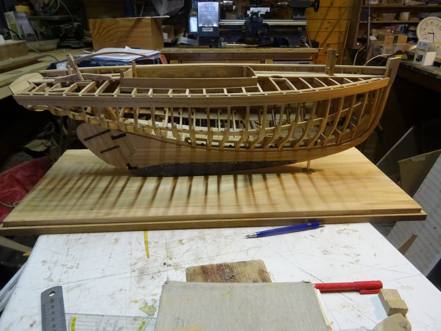
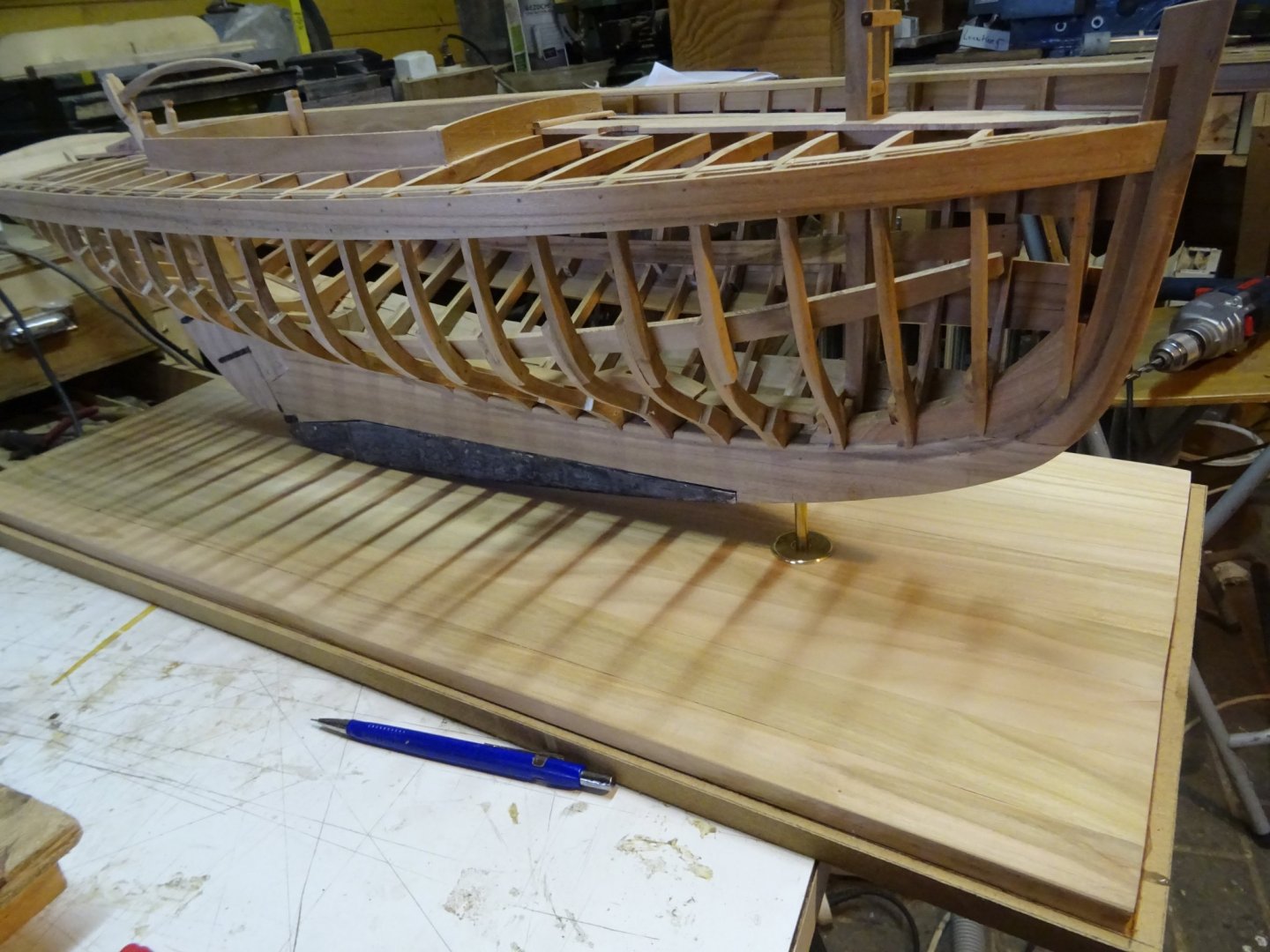
The model on its display board to look if everything is correct, then it can be removed again.
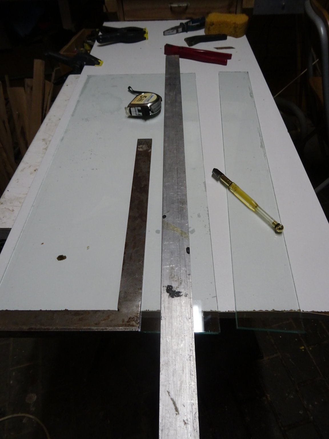
Around the MDF board comes a frame which is mitered in the corners. In the groove between the display board and the frame is space for a glass dust case.


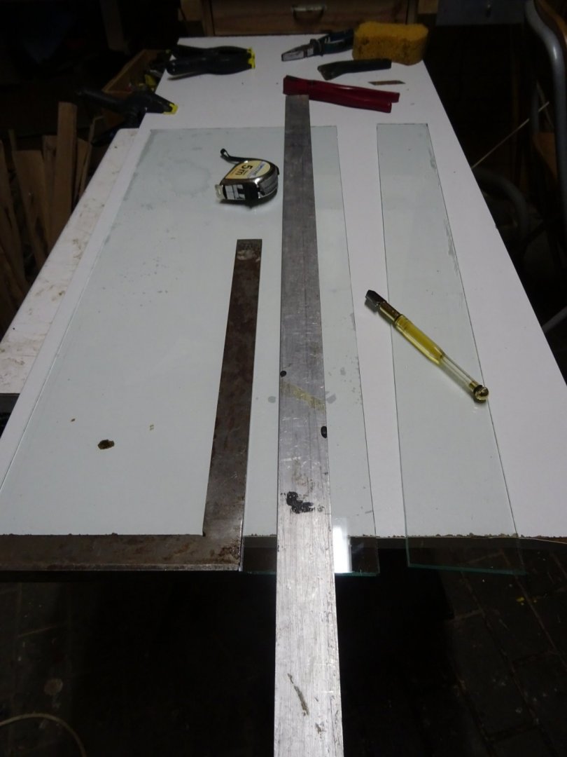
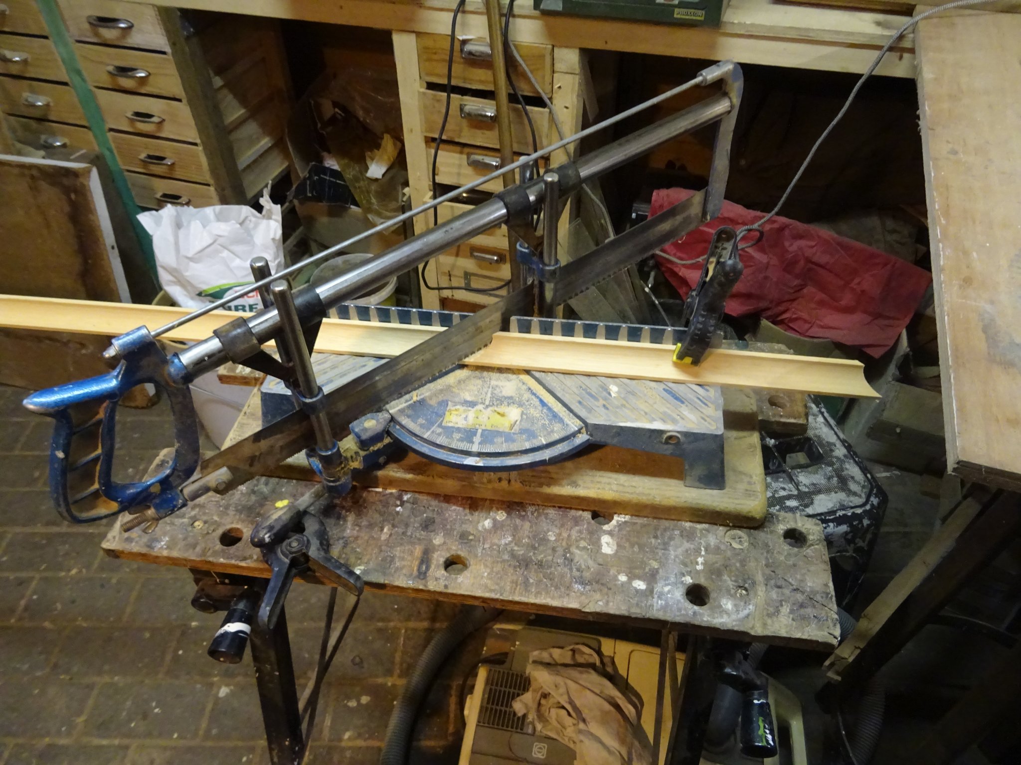
For the moment only food stores are open and it is not possible to buy new window glass, so I use some waste glass plates from an old greenhouse that I demolished and replaced in the garden a few years ago. I cut them to size.
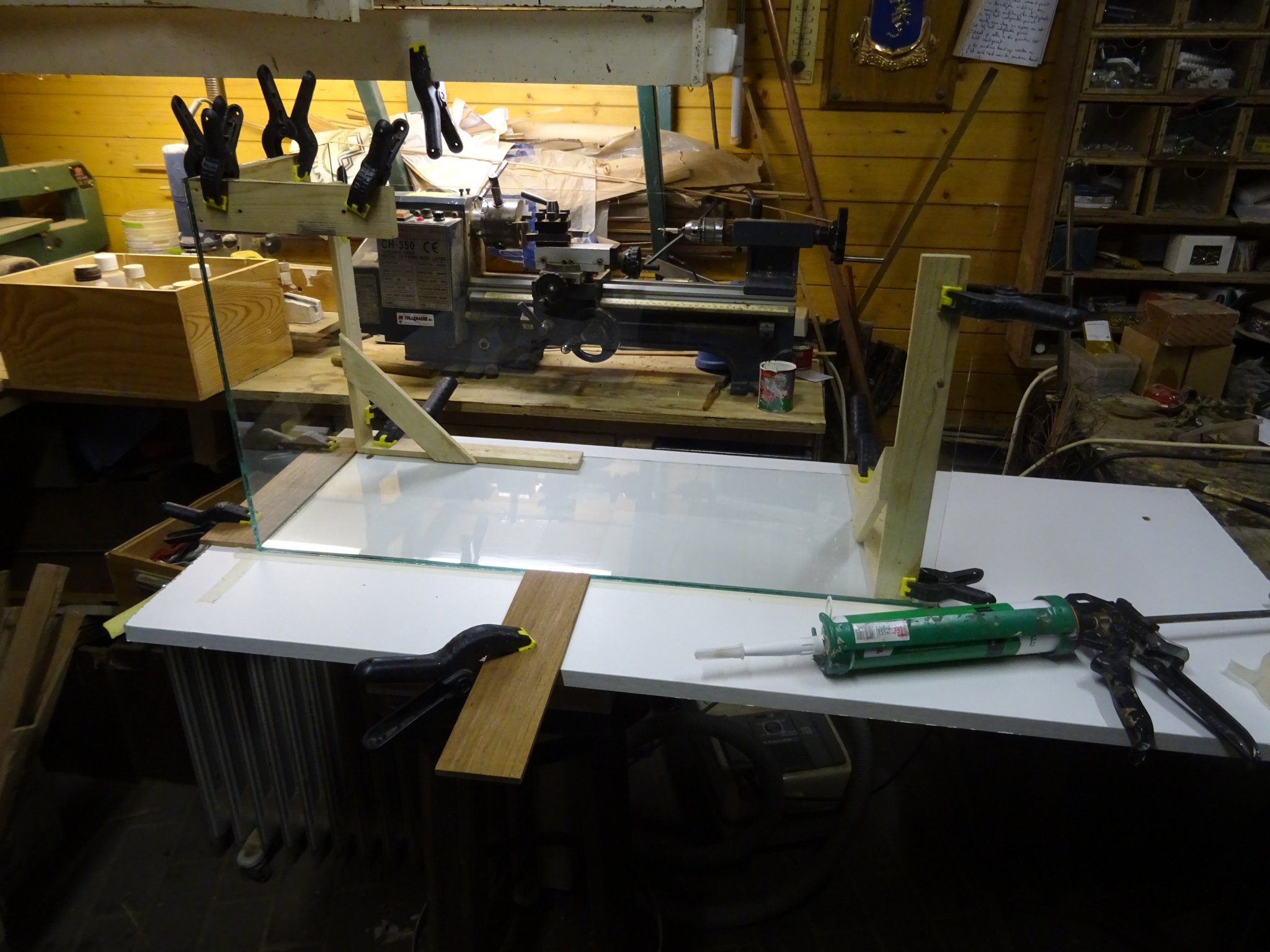
Gluing the case.
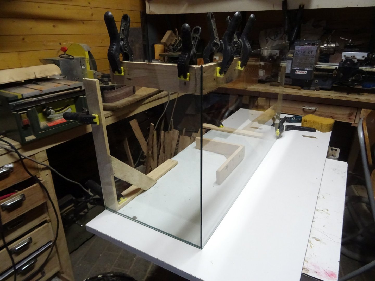


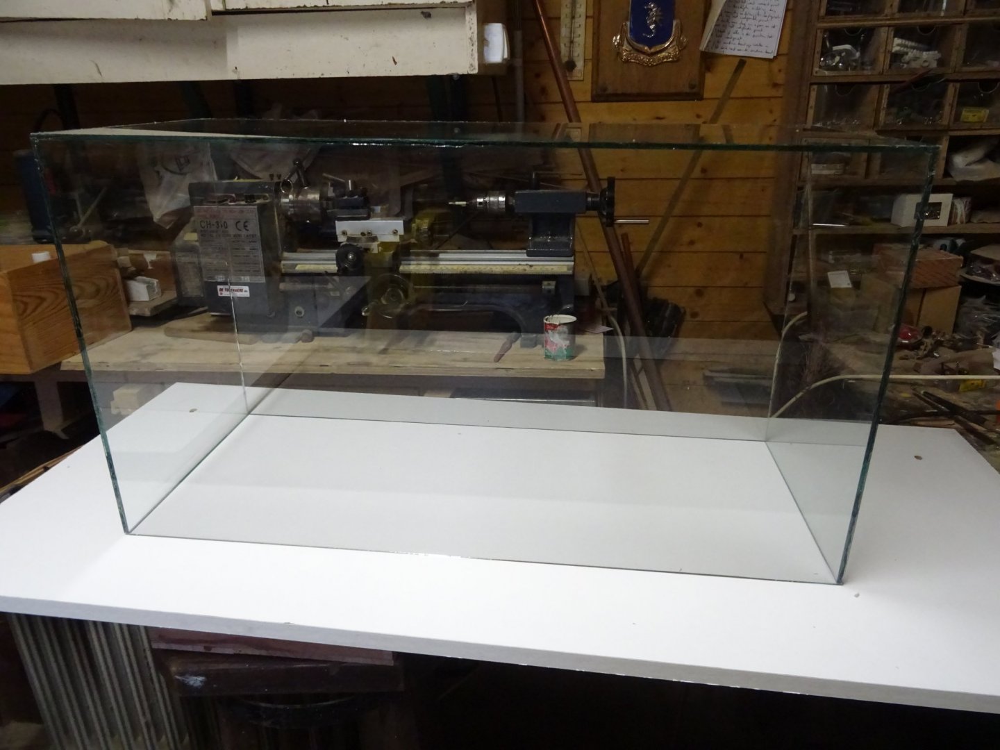
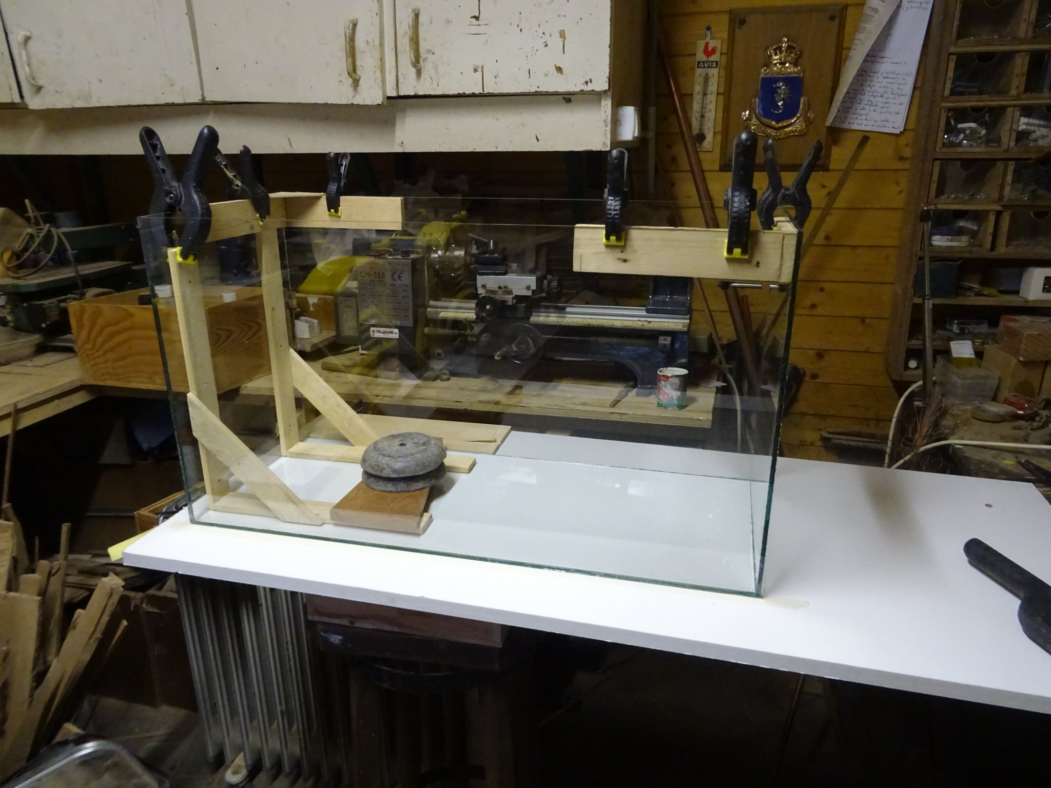
Taking away the supports is an exciting moment. Will the case fall apart or will it stand... It stands.

I can even pick it up and turn it straight up.
Thank you for reading
Thank you to follow
Thank you for the likes
and thank you for your constructive comments,
Till next week and keep it healthy!
-
Thank you very much Retired Guy, Gary and Eric.
This week I start with chapter II of the log.
CHAPTER II: The Lexicon
During the build of the model, I kept a list of all parts that I was making for it. I identified 54 different parts that I can name. Some of them appear several times; for example: there are 22 frames, 23 deck beams, ...
I am sure that a ship carpenter will know the name of a lot more pieces, but the aim of this model is to learn a landlubber the different parts of a small wooden vessel (see introduction). I am sure if he knows the 54 parts that are indicated in my lexicon, he will be able to start to converse with us, ship modelers.
1. The numbers
I thought about a method to indicate the different parts of the vessel on the model by numbers. It should look a bit presentable. My idea was to use the small numbered sheaves that are used in the 'bingo' board game. To distance them a bit from their 'bingo look' I planned to stamp their red side on a cushion with black paint and to varnish them afterward.
Finding bingo numbers turned to be a problem. The bingo games that are sold nowadays in toy stores don't contain wooden number sheaves anymore , they are all in plastic and are no more sheaves but numbered balls that are mixed in a kind of spinning drum system. My quest in the thrift stores and jumble sales in the wide neighborhood (before the Corona lockdown) was in vain.
Finally I found what I looked for on E-bay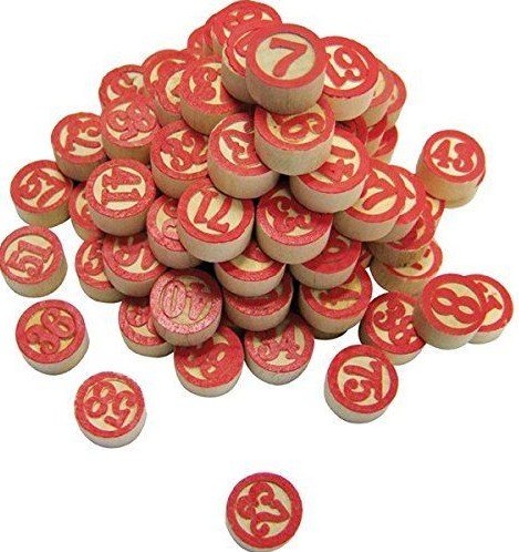
I buy them without hesitation. A couple of weeks later I am the proud owner of an old fashion bingo game!
Can you imagine how big my disappointment was to discover that the bingo sheaves were at least twice the size that I had expected?
If I glue 54 such a whopper numbers on my model it will be completely covered. The parts that I want to show will be overlaid by their numbers. That is didactically no so well thought-out.
Now it seems that I can't outsource the production of my numbers, I will have to make them self. This is a forum for scratch projects, after all.
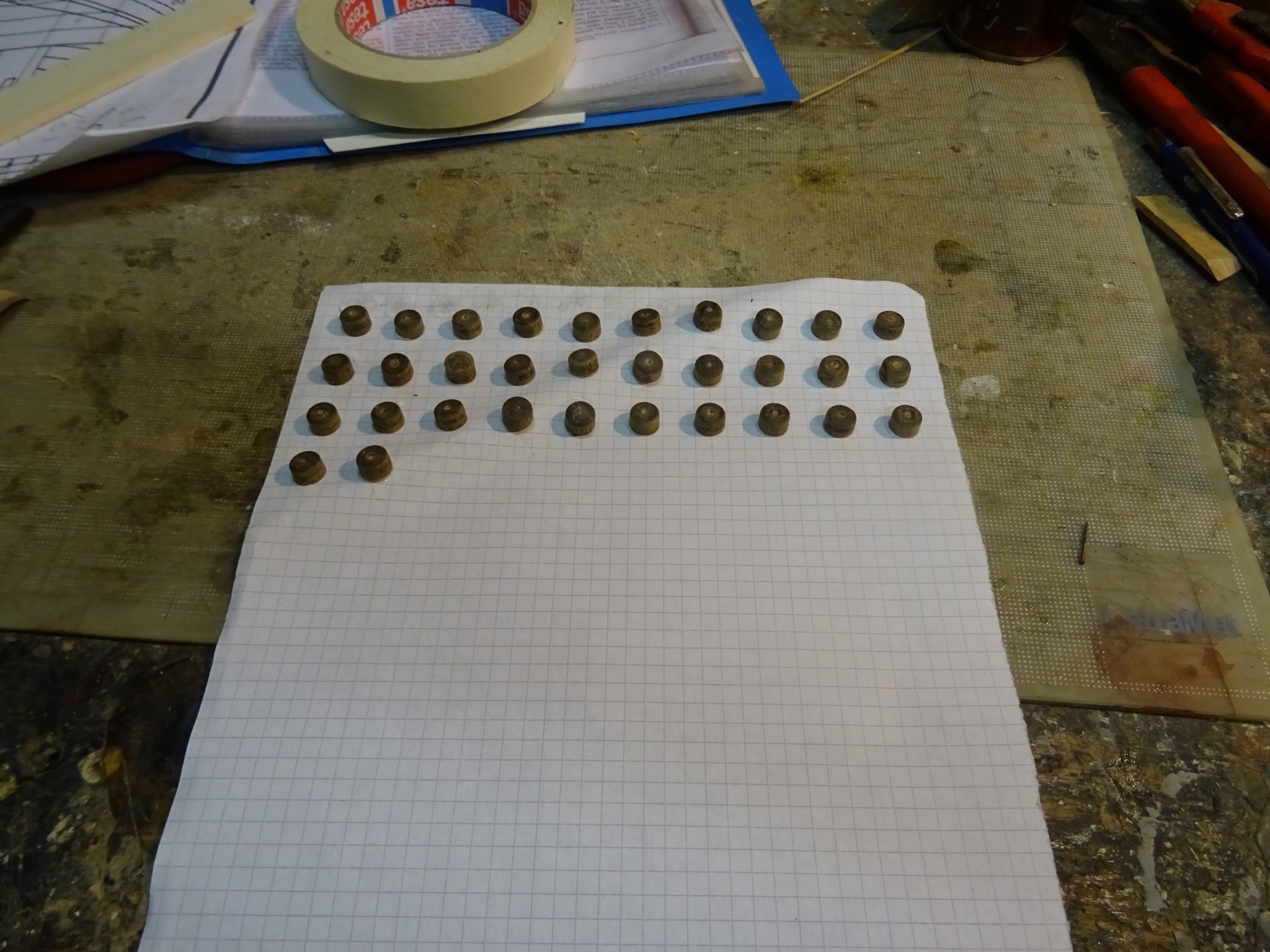
I start with the making of a series of hard wooden sheaves at the size that I want to have.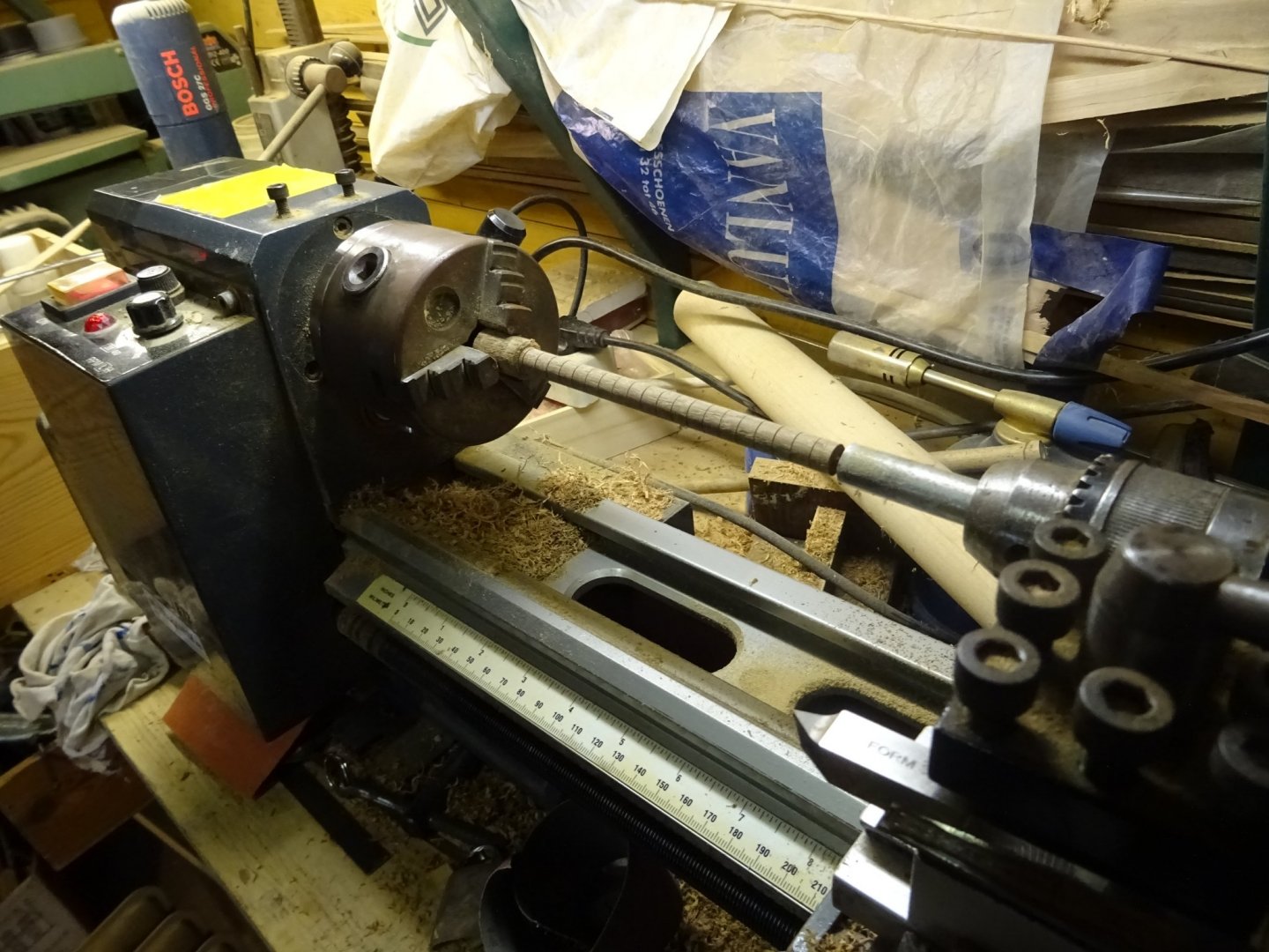
I glue them on a piece of paper. That makes the further treatment easier.
I varnish them twice with brilliant varnish.
Now the moment has come to experiment:
I dilute some yellow paint with turpentine until the viscosity is a little bit thicker than that of ink. With this fluid I try to write the numbers on the varnished sheaves with the help of a calligraphy pen.
It works! I judge the numbers as acceptable (easy to judge yourself). Now I can make the rest of the sheaves and number them.
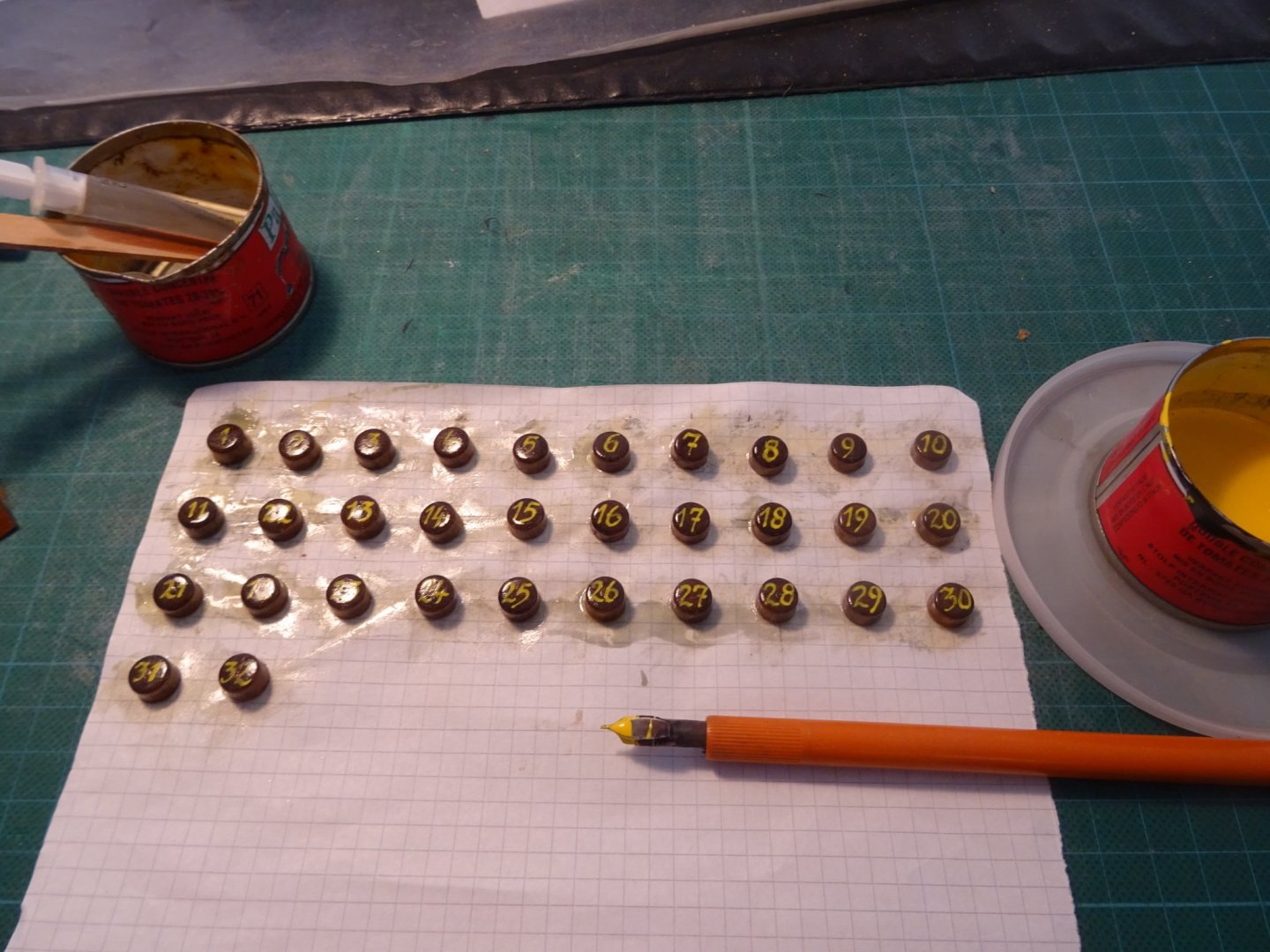
Once the numbers are written and dry I varnish them on top of the writing. That gives them an enamel look.
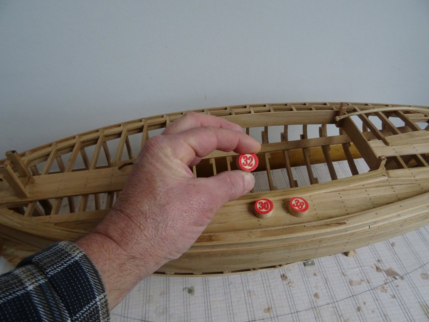
Here are all my numbers, some are doubled for the parts that will be shown from both sides of the model.
I lay also a couple of bingo numbers for size comparison.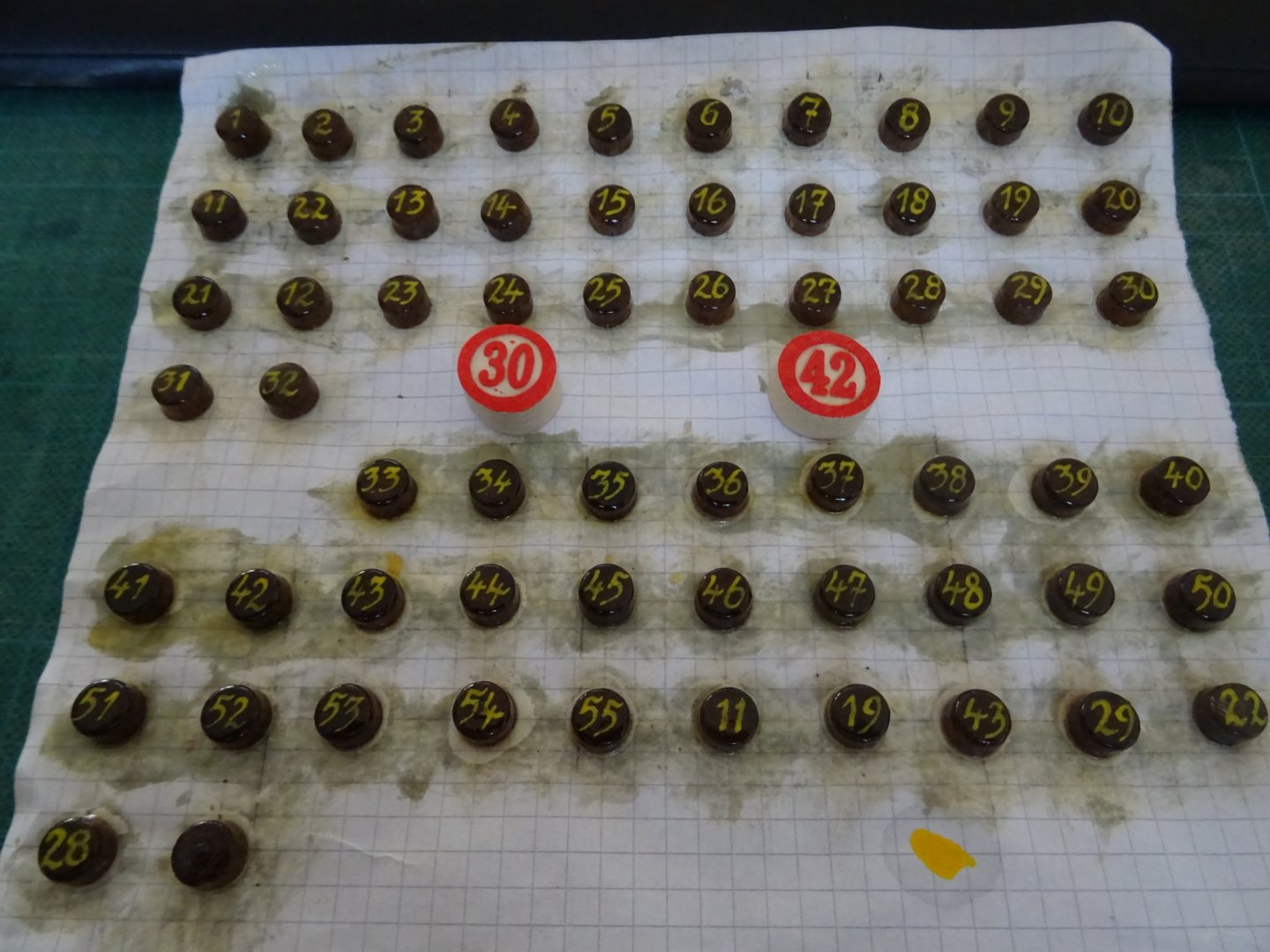
- KeithAug, GrandpaPhil, Baker and 5 others
-
8
-
-
Yves,
When looking to the real sub pictures of the previous post, the control room seems me a very complicated compartment to realize.
The chart on your chart table has an English inscription 'Baltic Sea'. Did the Kriegsmarine use charts with English lettering during the war?
-
Larry, Congratulations for finishing this beautiful model. A good idea to place it on that Camp plaque. She looks really nice.
Will you make a log for the three next knockabouts?
- mtaylor and FriedClams
-
2
-
She's indeed big. It will be a magnificent model. I am also curious about the diorama.


Golden Hind (ex-Pelican) by Baker - FINISHED - scale 1/45 - Galleon late 16th century
in - Build logs for subjects built 1501 - 1750
Posted
Those pumps worked very well, Patrick. They are perfectly round, and that without using a lathe!