


G.L.
-
Posts
1,553 -
Joined
-
Last visited
Content Type
Profiles
Forums
Gallery
Events
Posts posted by G.L.
-
-
8. The cockpit coamings
While making the rail at the portside (see part 7) I made also the coamings around the cockpit.
Round the opening of the cockpit comes a coaming to prevent the flooding of the water which is splashing over the deck .
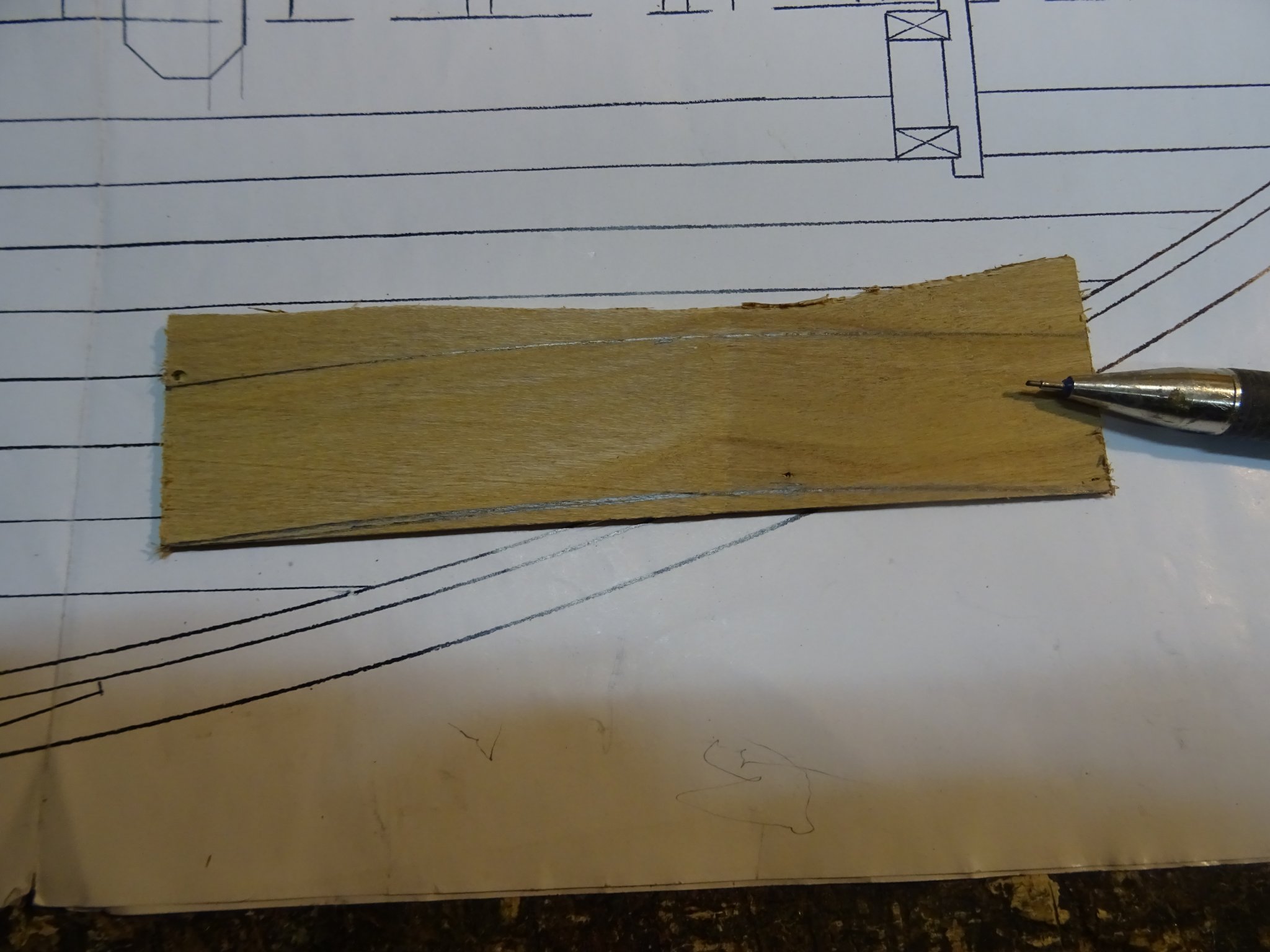
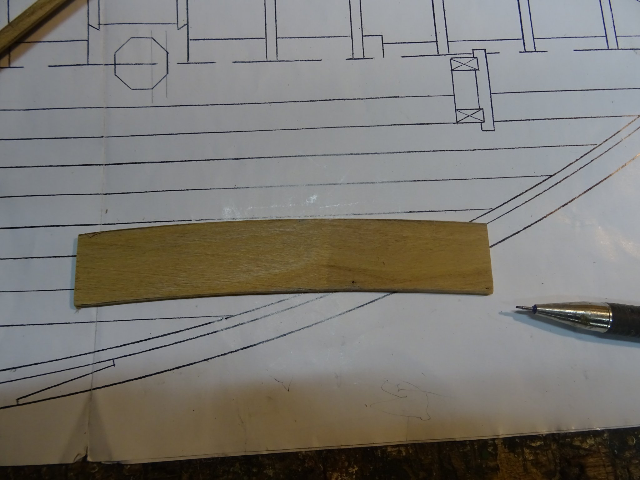
I draw the deck rounding on the forward and astern plank with the same template that I used to draw the deck beam shapes.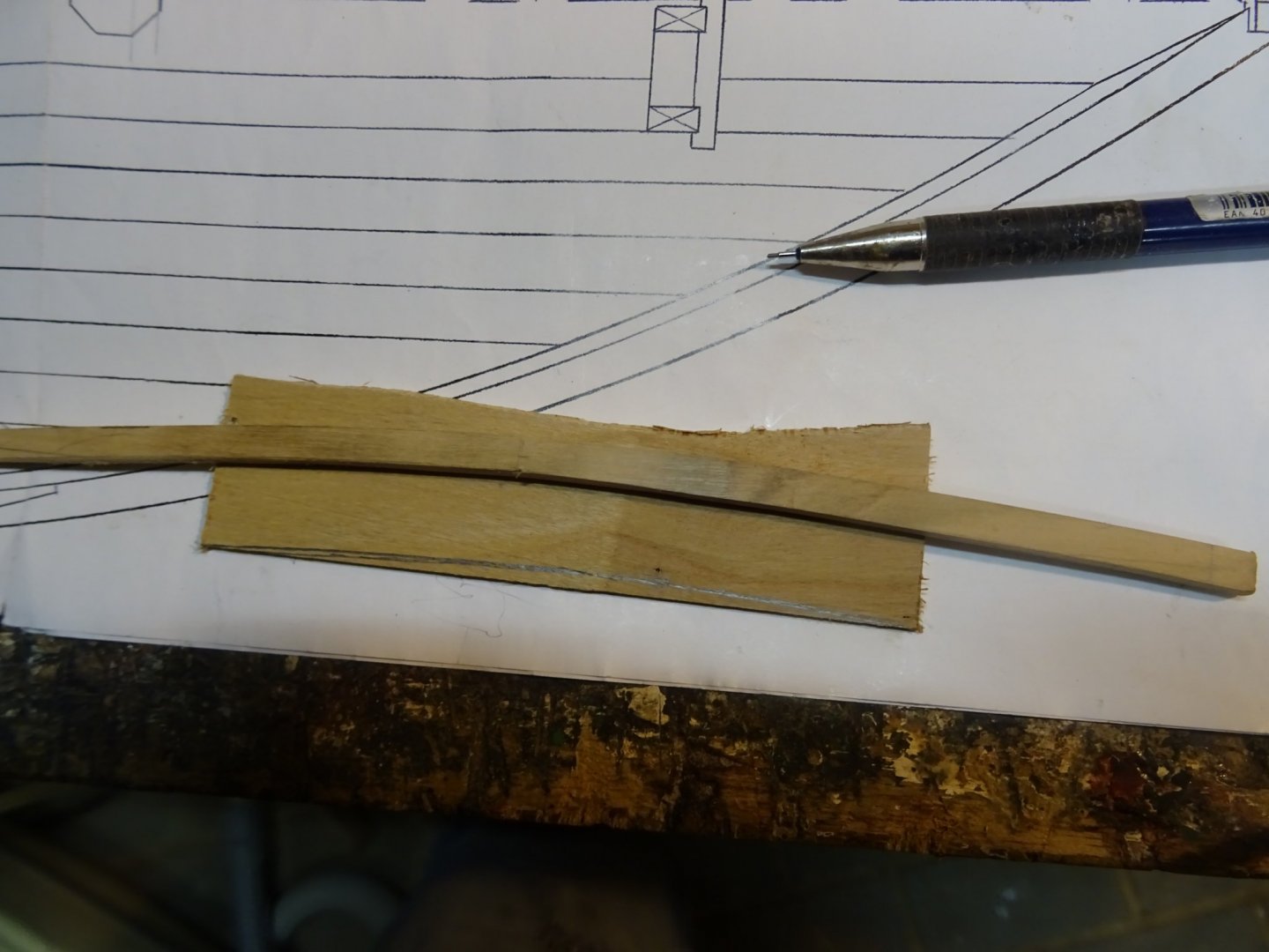
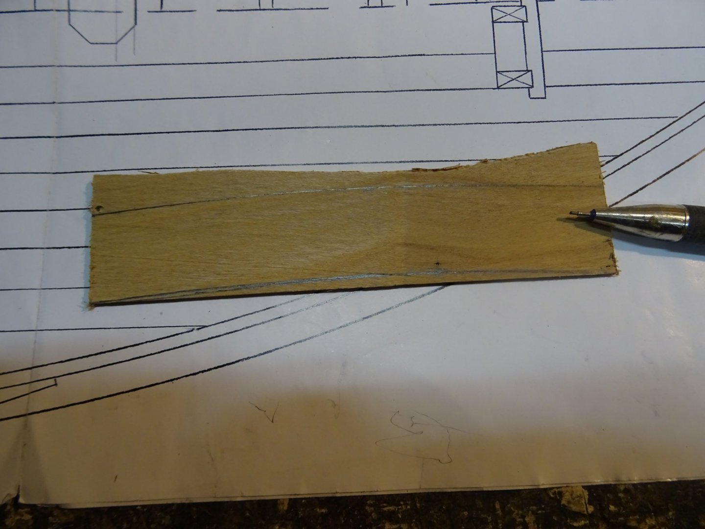
... and saw them out.

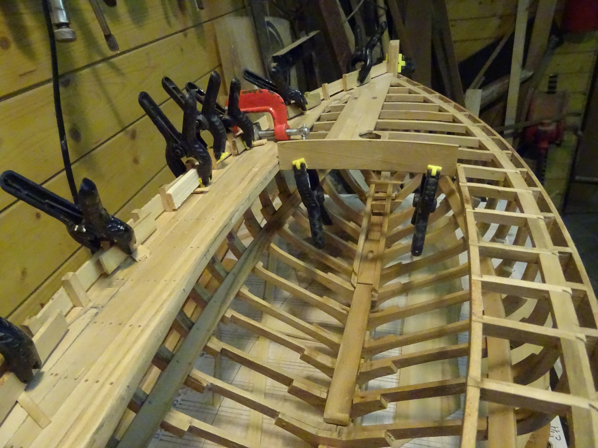
Fitting the forward plank.

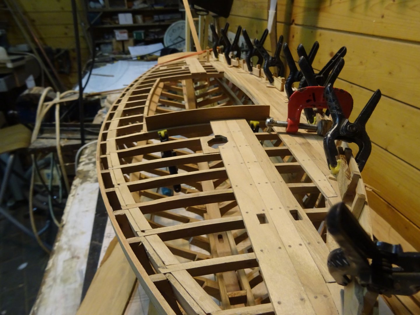
Gluing the planks.

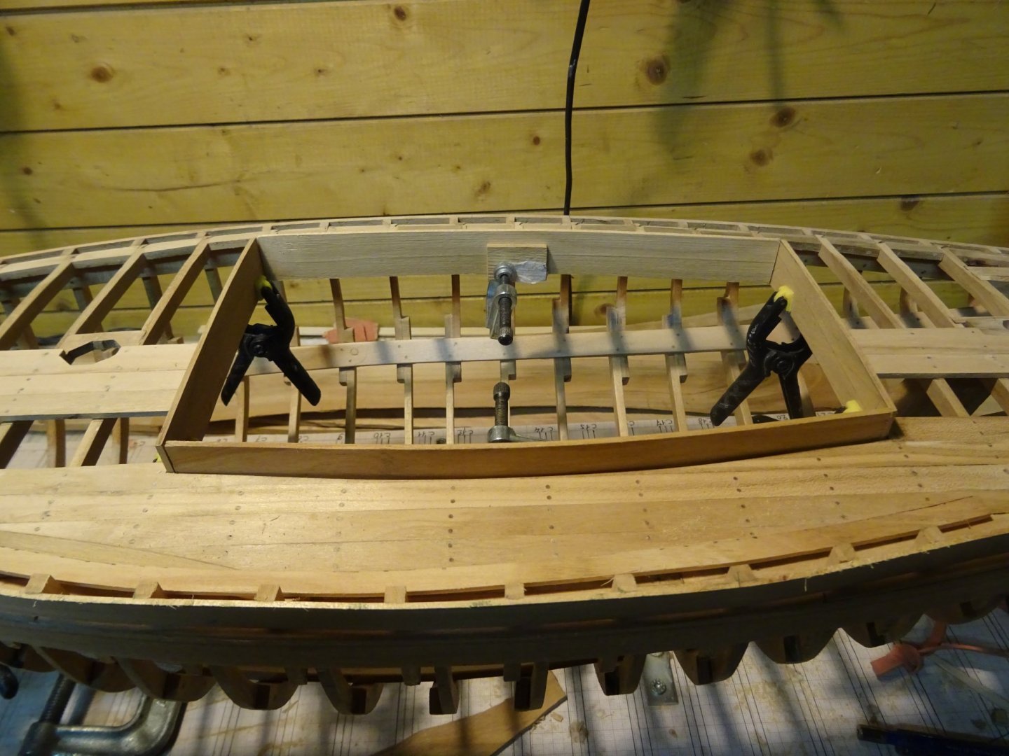


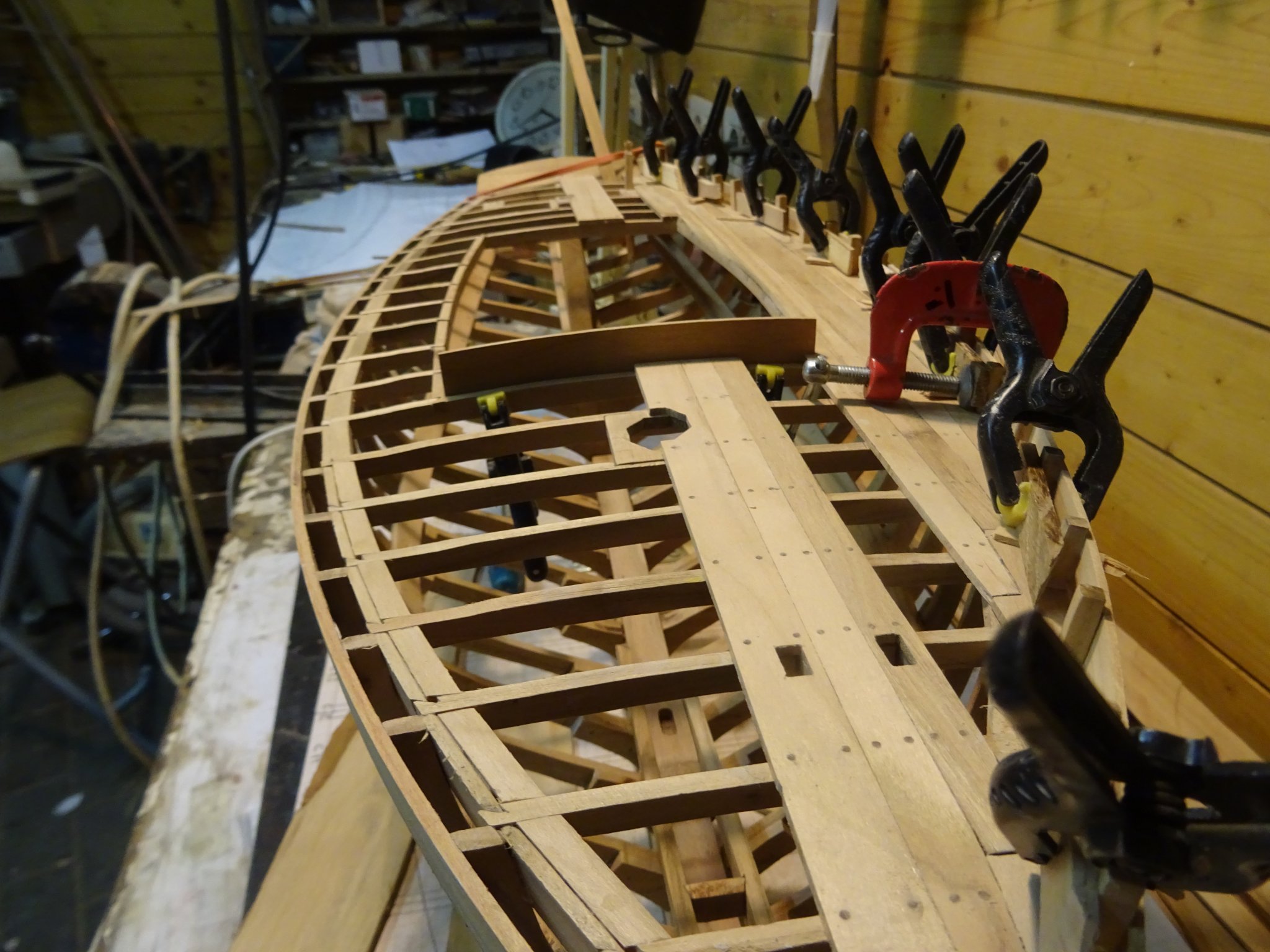
The reinforcements of the after corners of the coamings are at the same time bollards.
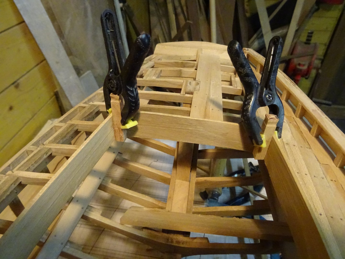
The two forward corner pieces are just reinforcements.
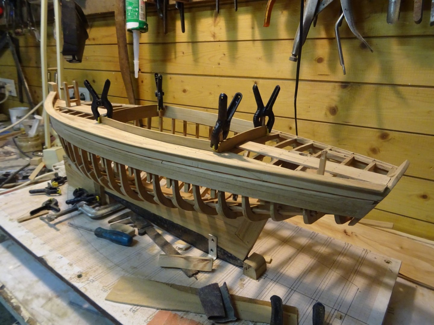
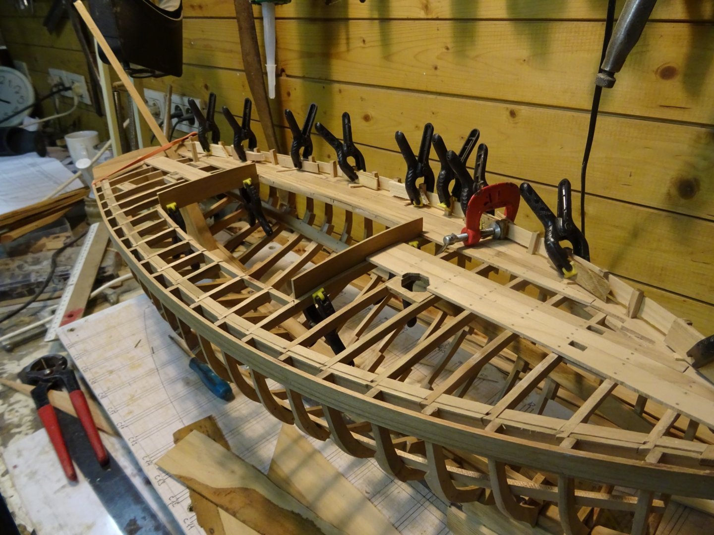
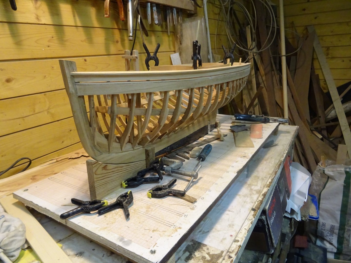
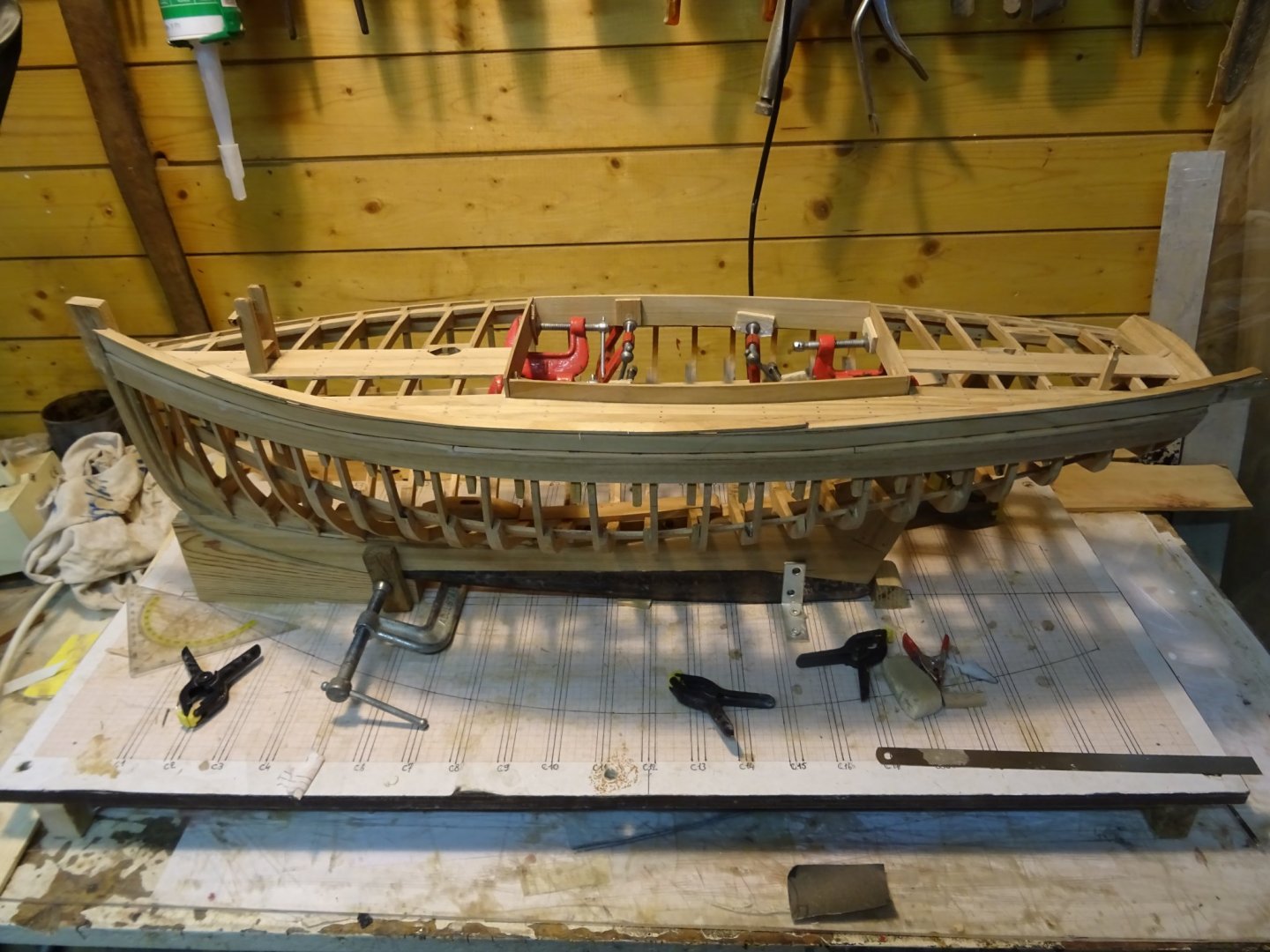
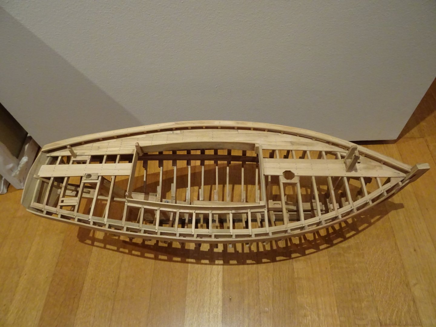
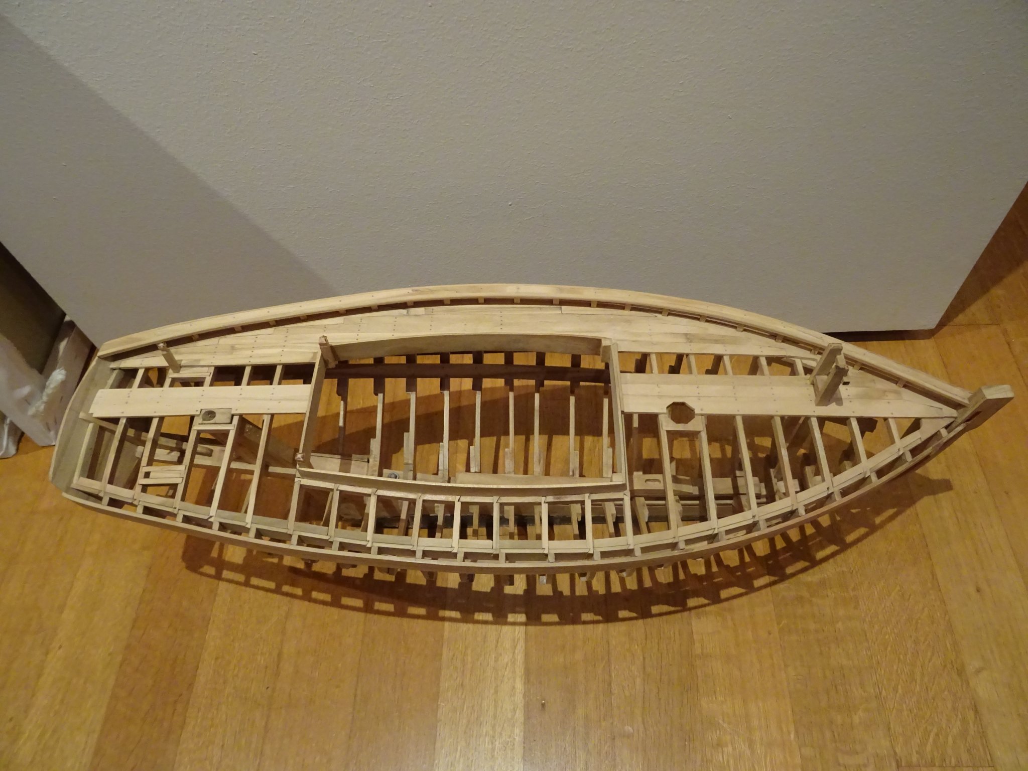
The model in its current state.
Thank you for reading
Thank you to follow
Thank you for the likes
and thank you for your constructive comments,
Till next week
- SJSoane, michael mott, Valeriy V and 18 others
-
 21
21
-
-
On 3/5/2020 at 7:16 PM, vaddoc said:
Wow GL, I have not been able to visit for a while but you have made good progress! Very nice joinery, nice fairing of the frames as well. Another thing you seem to have tackled with ease is the curvature of the deck beams-I struggled with this myself.
Did the original boat have only one pair of stringers on the inside the frames?
Vaddoc
Thanks Vaddoc,
On the drawings of Mr Lohmann there is only one pair of stringers. I guess there will be also one pair of stringers to carry a kind of floor in the cockpit.
-
-
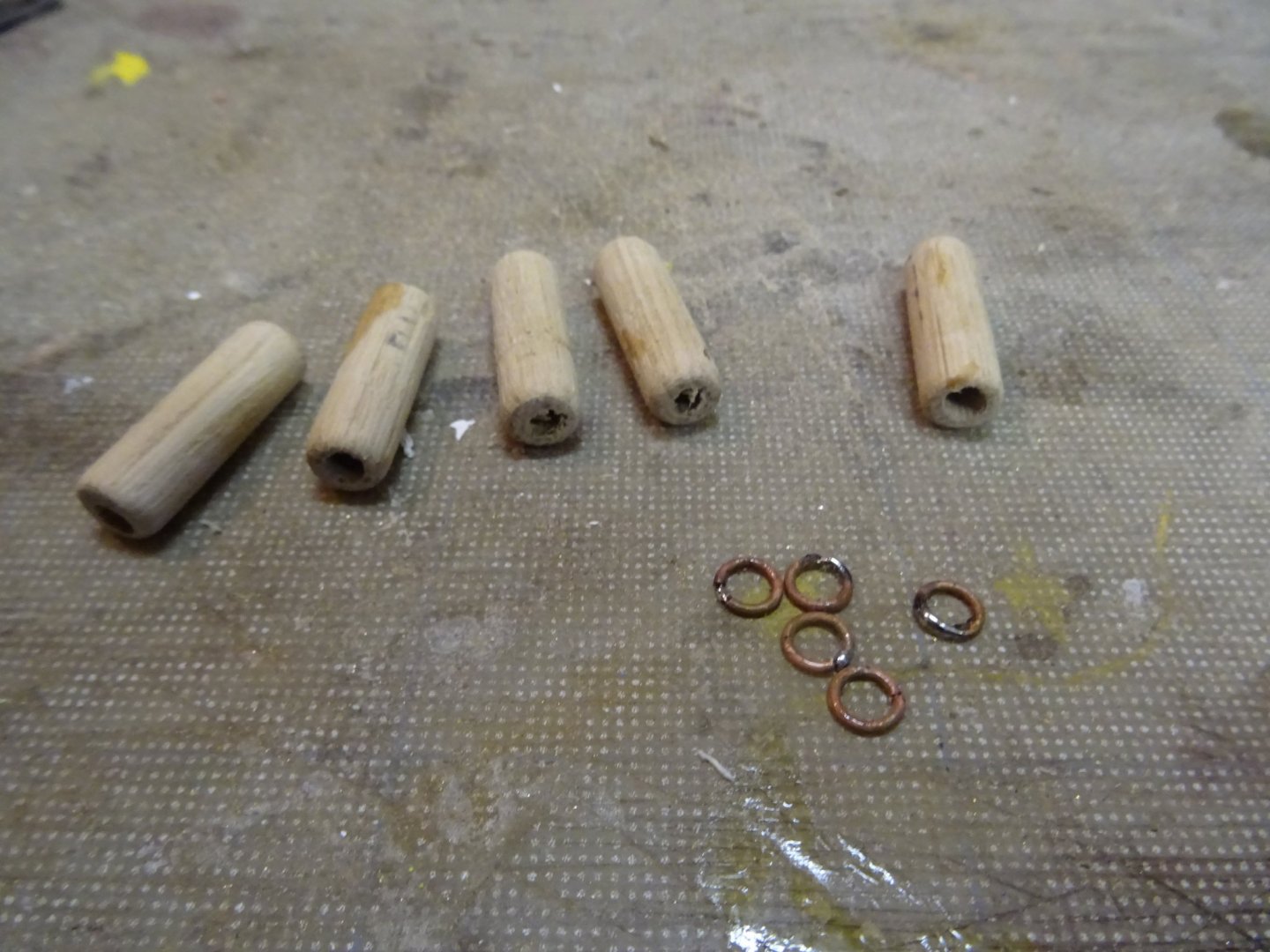
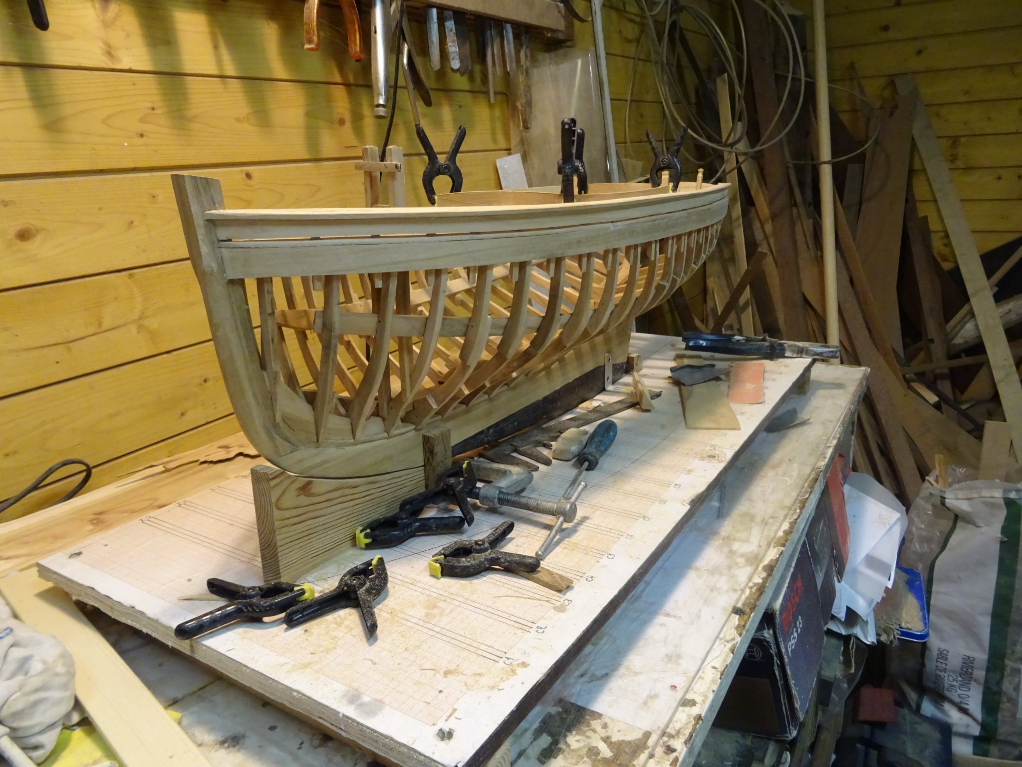
14.6 Rope fenders
I want to have four rope fenders on board of my boat. I make first some wooden tubes (Ø 8 mm and length 3 cm) and some copper rings (inner Ø 4mm).
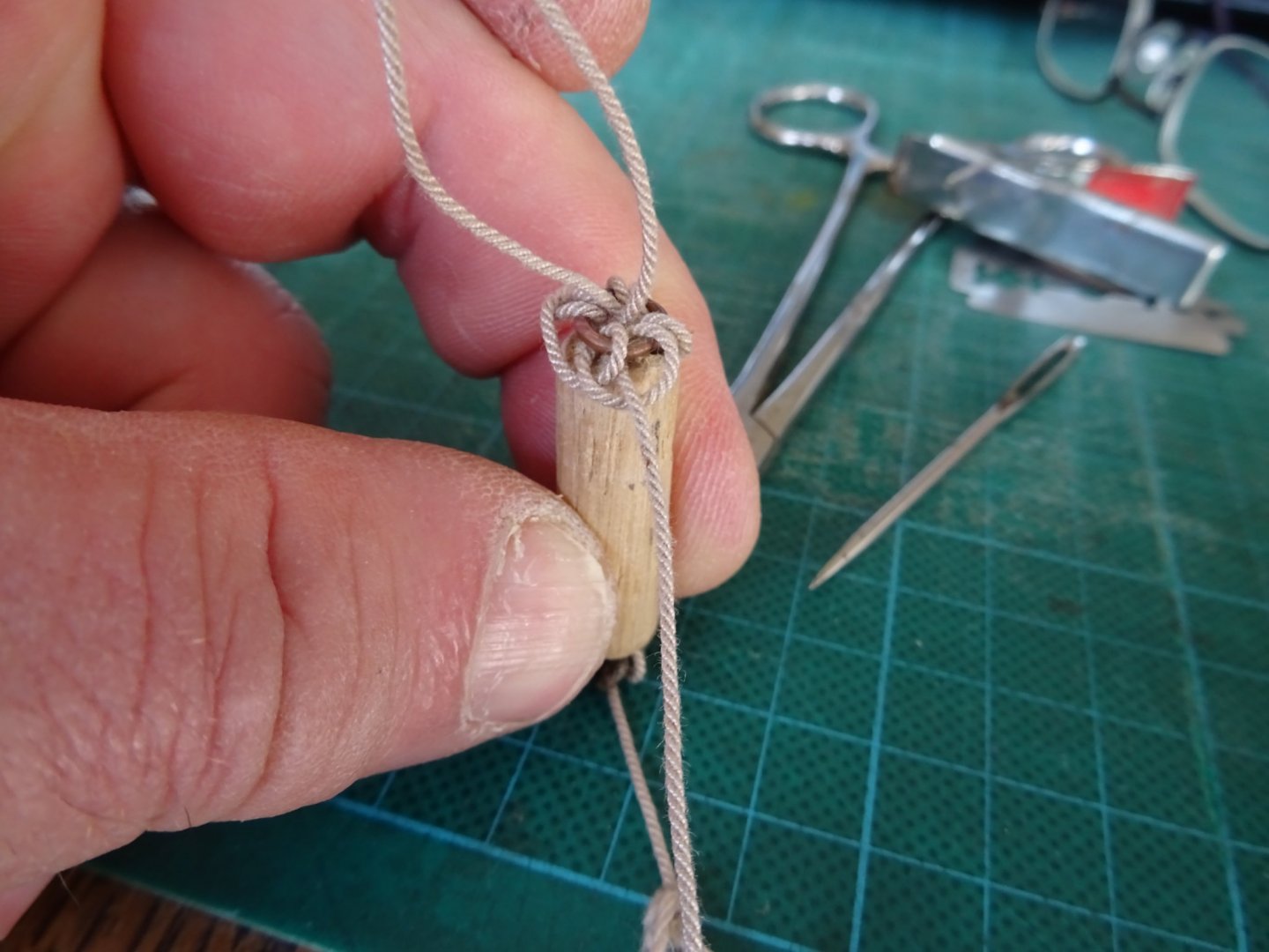
Then I pass the rope four times through the tube, in this way I have at each side and end of rope and a loop of rope. I stick the copper ring through start to make half hitches around it.
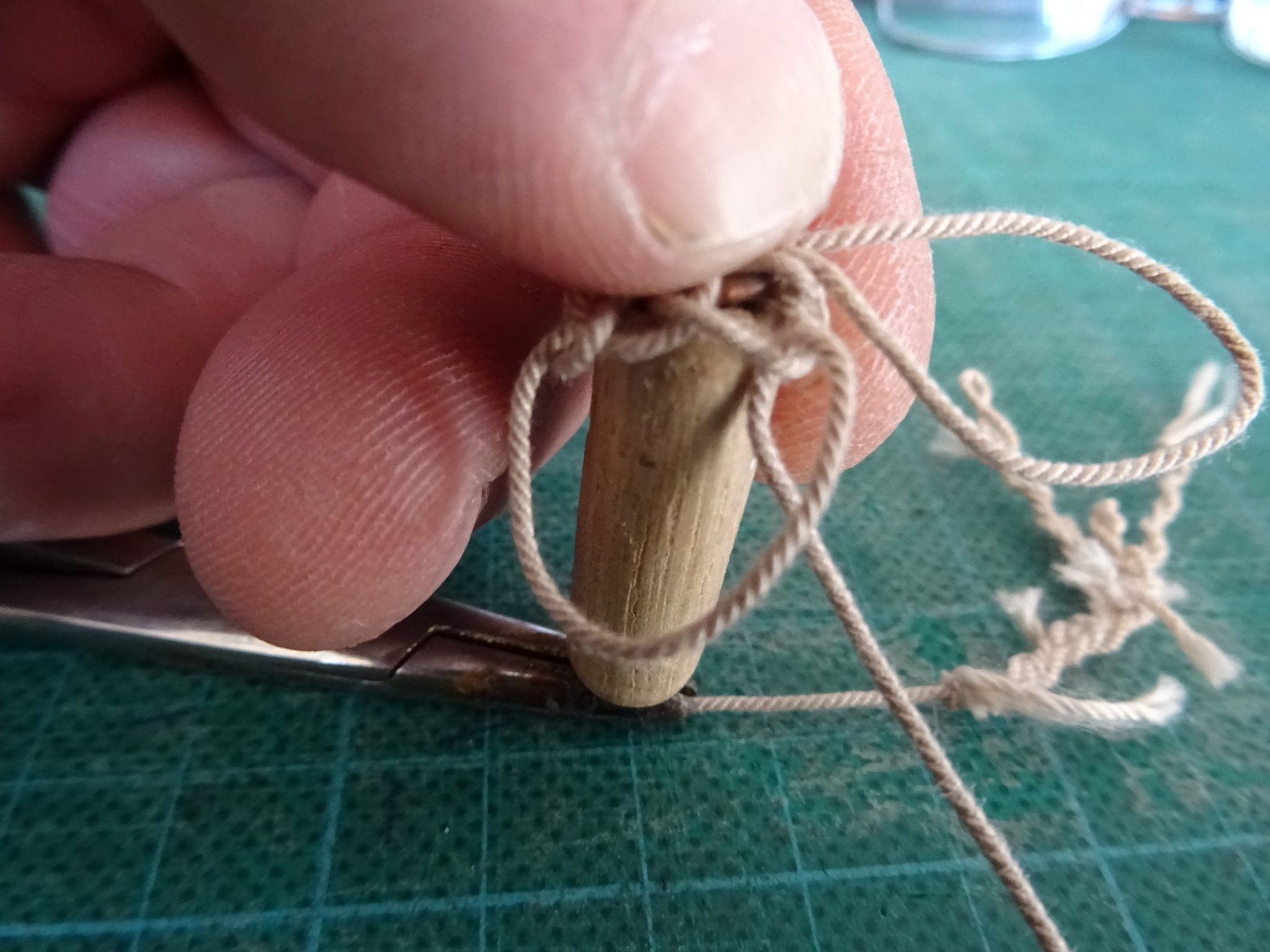
When I am fully around the ring, I continue to make half hitches, but now in the loops of the previous half hitches.

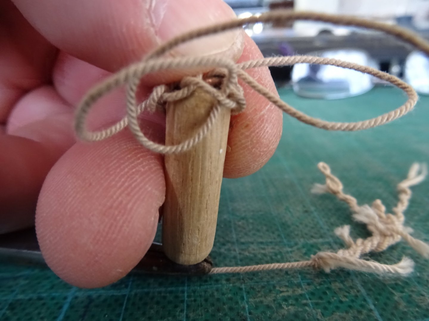
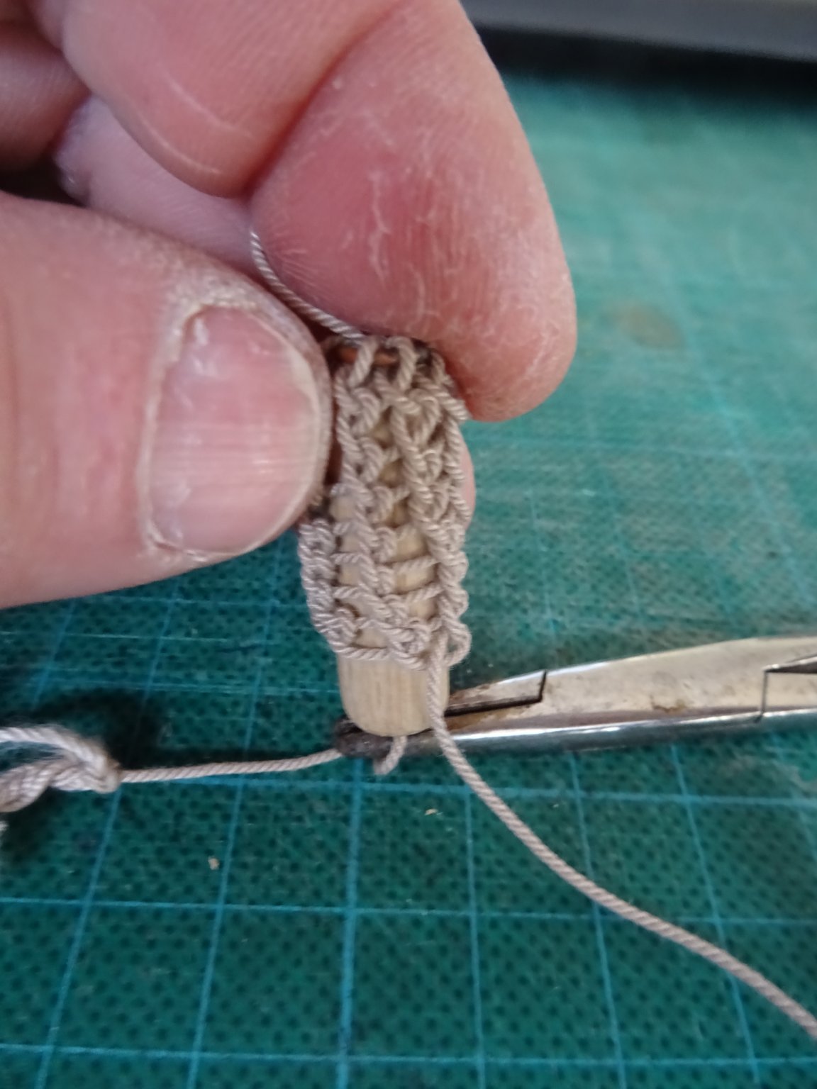
And that continues downwards the tube.


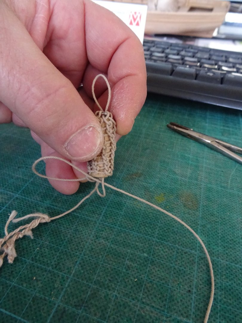
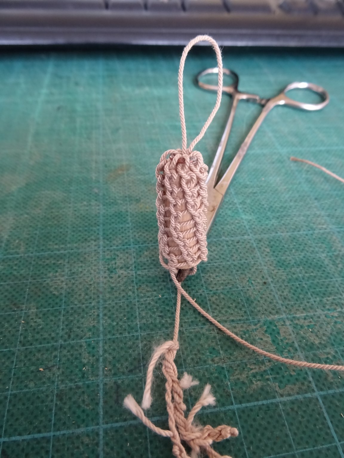
When all the half hitches are made the loose end goes through the bottom rope loop. Then the loose end has to be pulled tight until the top loop has the desired size and the bottom loop disappeared in the tube. Before cutting the loose end I fix it by injecting wood glue in the tube. When that it dry, the loose end can be cut off and there is no more risk of pulling out the upper loop from the fender.
I soak the fenders in dark stain to give them a more realistic look.

Two of the rope fenders hanging outboard.

On this last picture you can also see that meanwhile the main sail is hoisted, but that is for next week.
Thank you for reading
Thank you to follow
an thank you for the likes
Till next week!
- Retired guy, Baker, michael mott and 20 others
-
23
-
14.5 The bailer
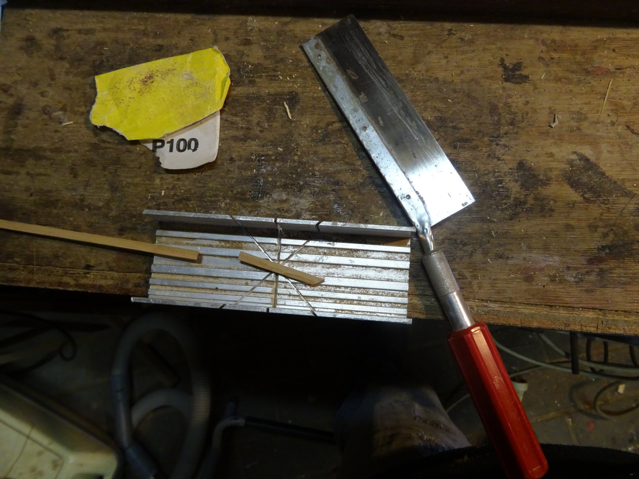
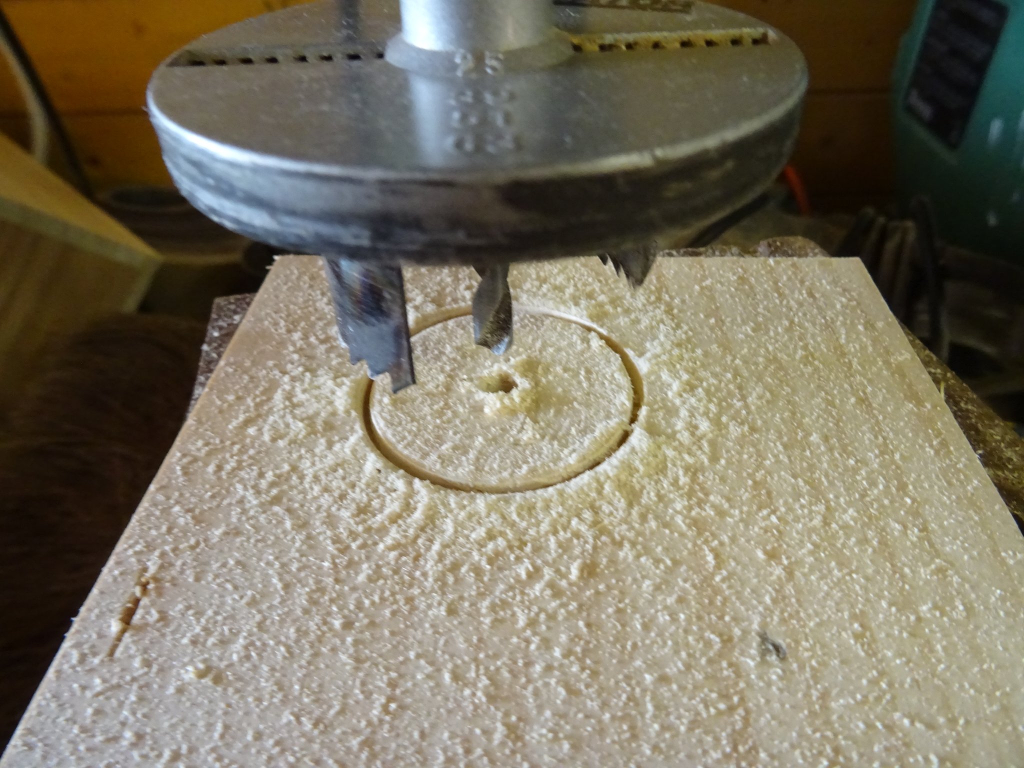
The body of the bailer consists of a small wooden cylinder which I drill hollow.
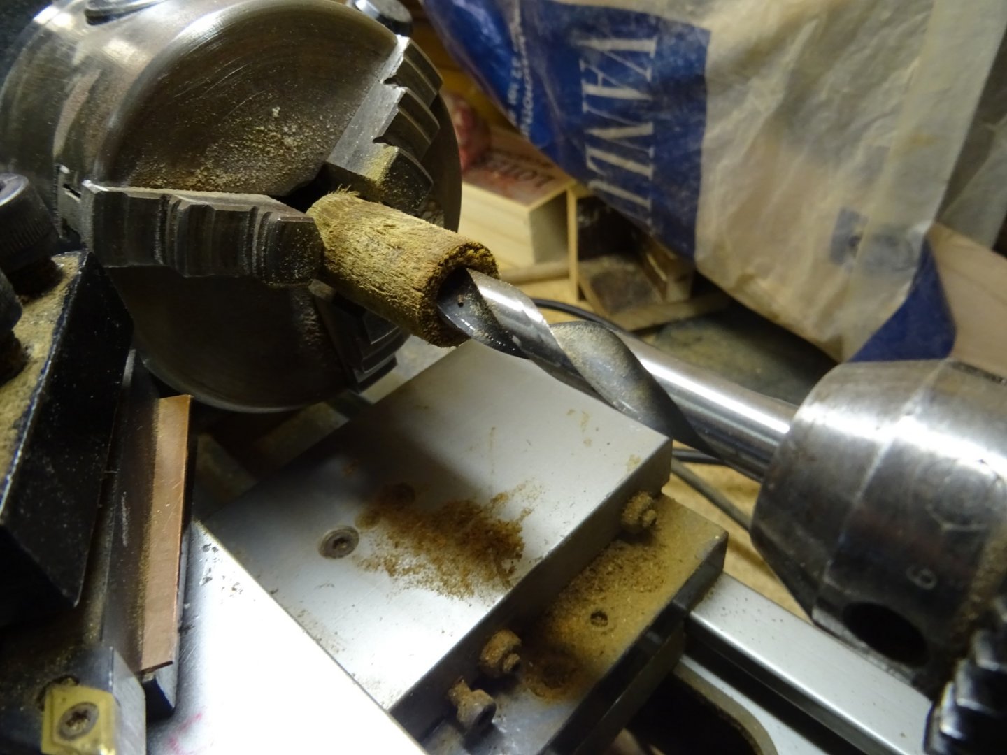
I saw it diagonally.
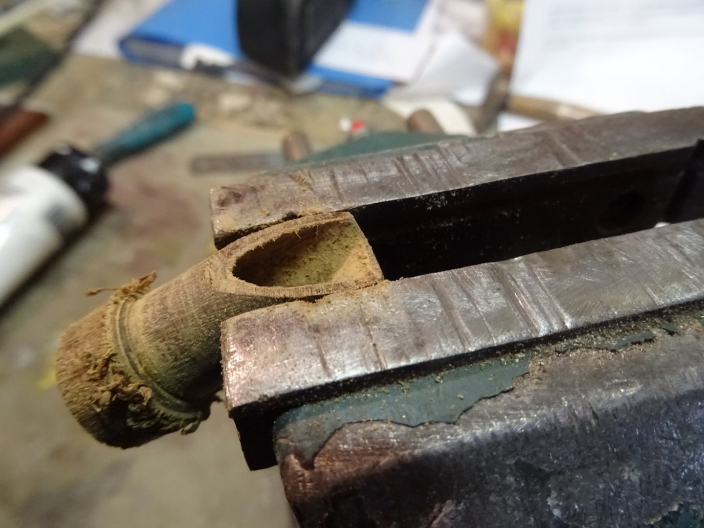
After the excess is sawed away and the piece is sanded, the handle can be placed.

The bailer.

- mtaylor, GrandpaPhil, KeithAug and 8 others
-
11
-
You're welcome, Yves.
Some more progress:
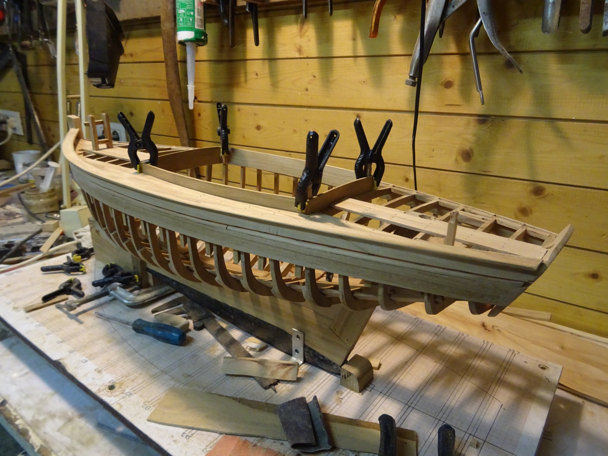
7. The rail
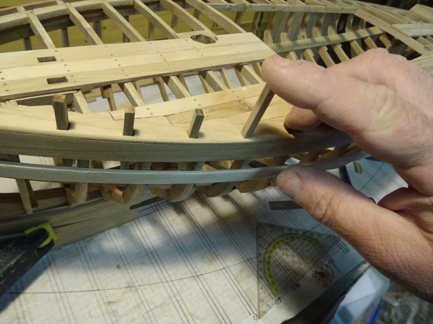
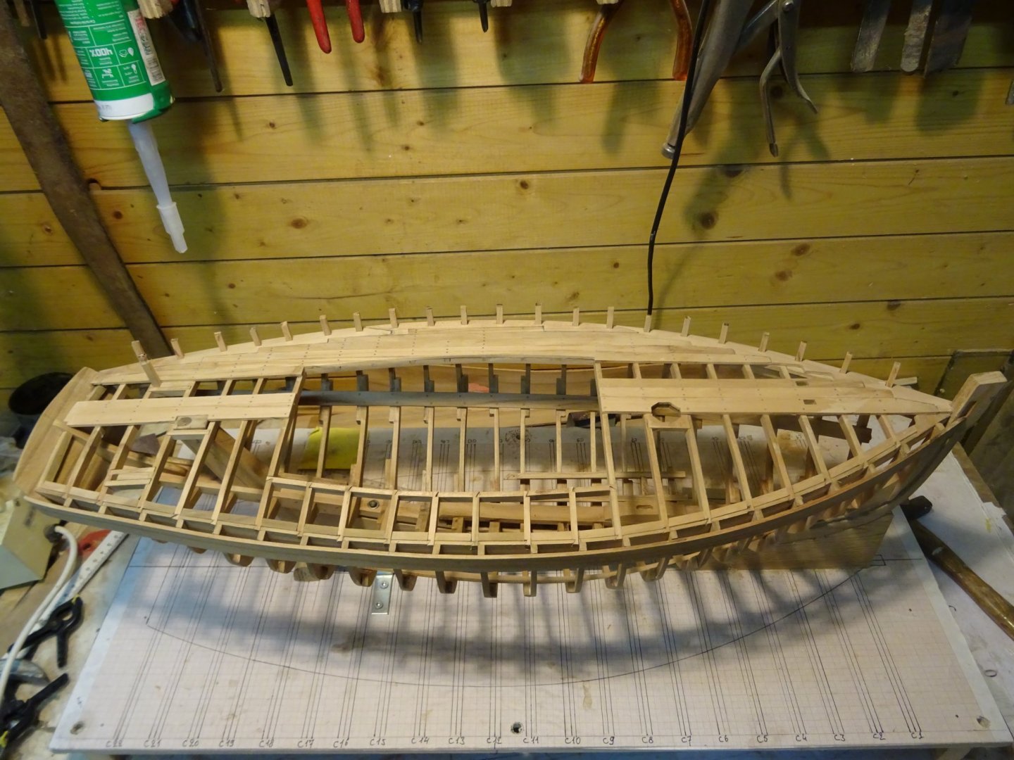
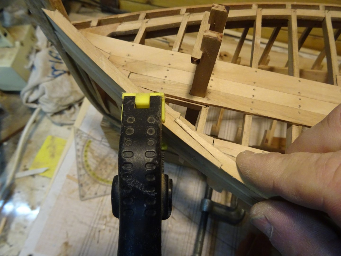
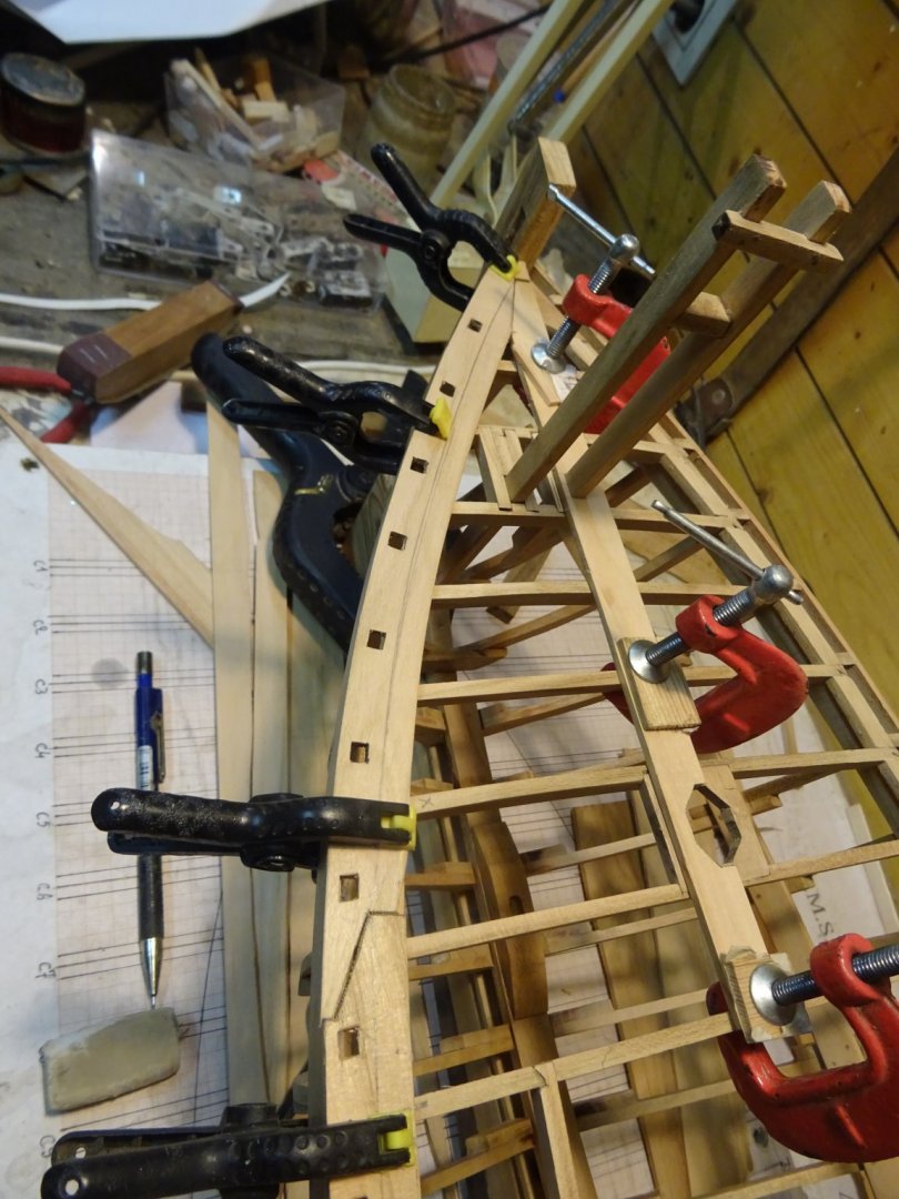
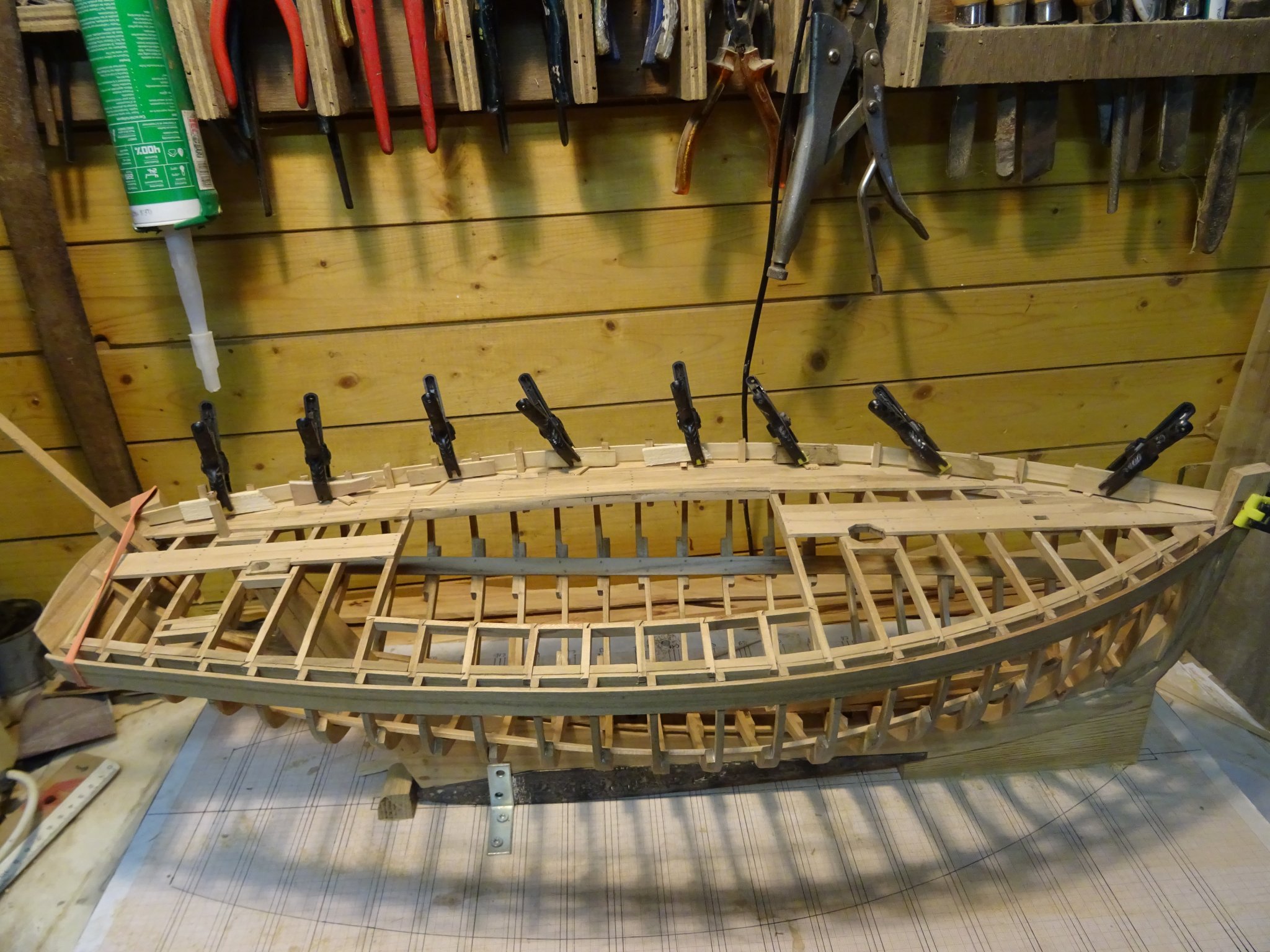
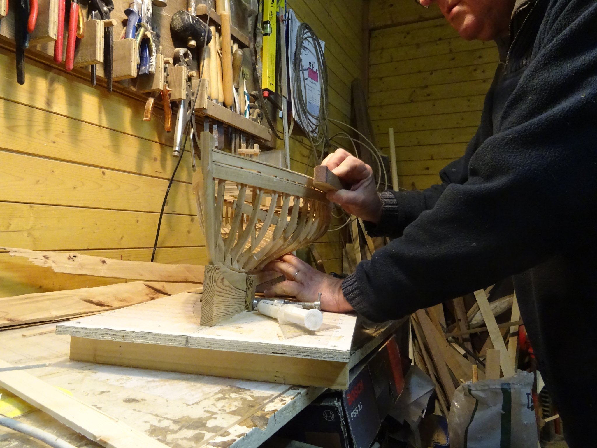
The boat has a low rail, supported by 21 stanchions which are not part of the frames. To be able to place the bottom side of all stanchions on a smooth line, I fasten a lath to mark the level.

The bottom side of the stanchion is sawn at 45°.

I insert some wood glue in the stanchion hole ...

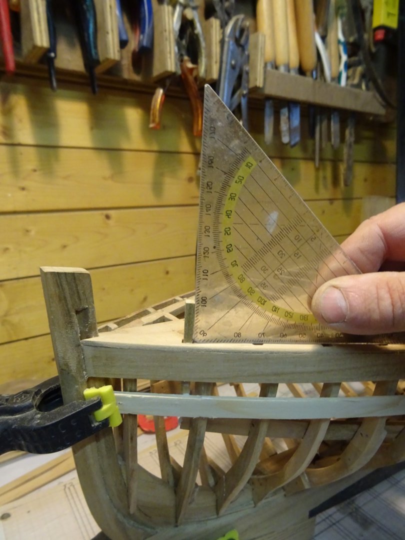
... and push the stanchion into place.
Checking if the stanchion is standing vertical.
The stanchions are glued against the inside of the wale. Below deck they are held into place by small temporally wedges between the beam clamp and the stanchion.

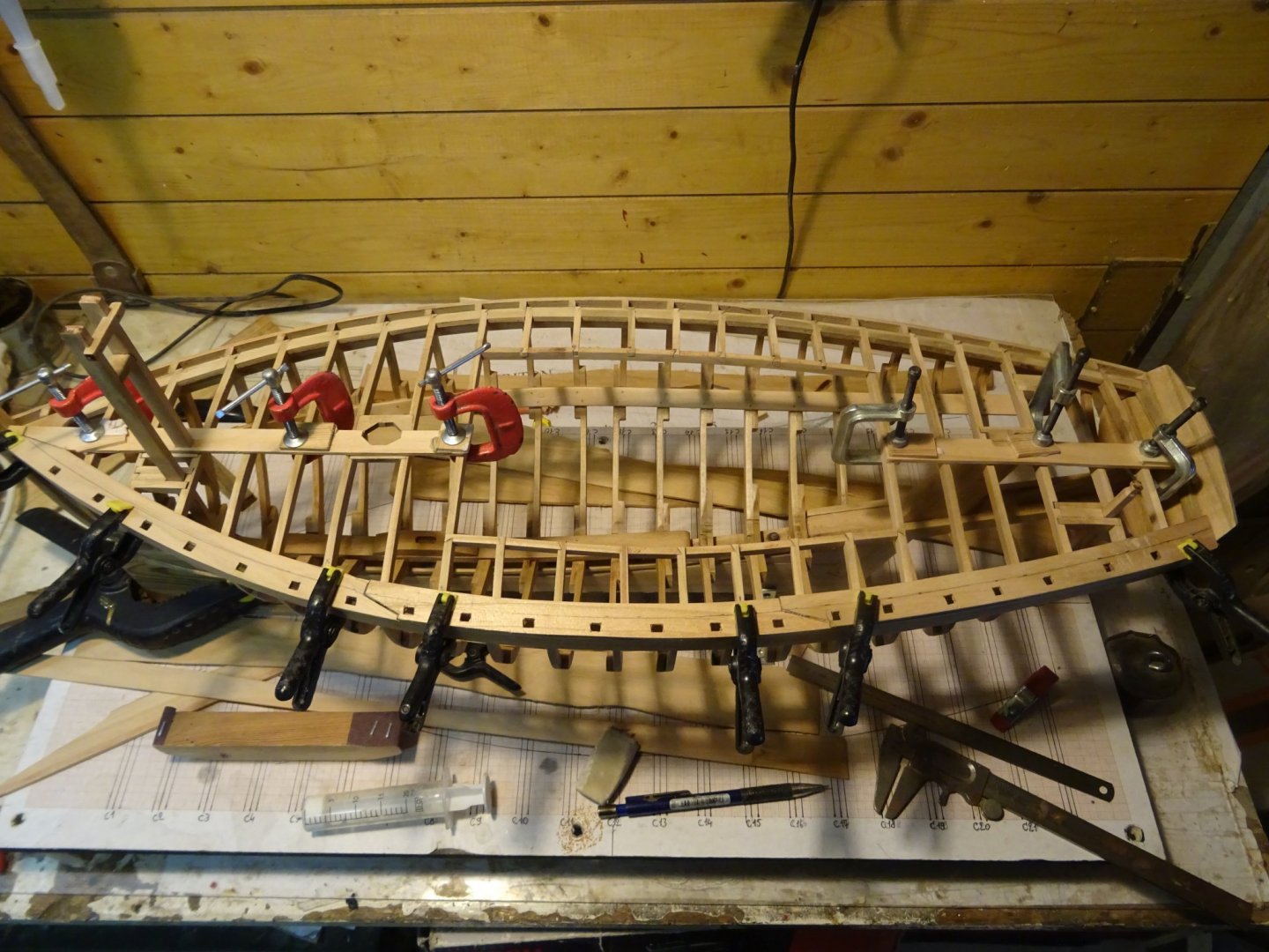
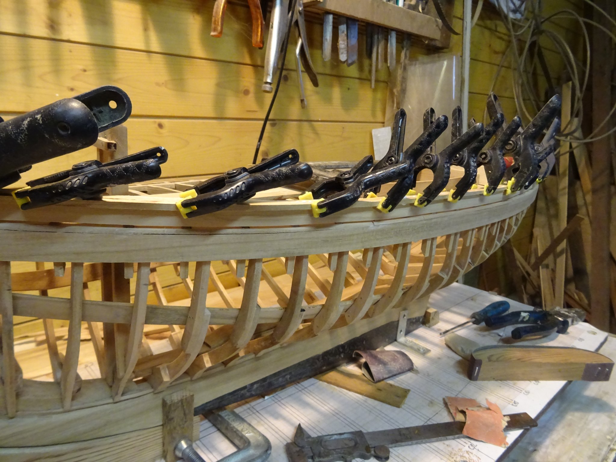
All 21 stanchion into place. They are a little bit longer than needed. The excesses will be sawn when the rail plank is placed.
Wedges and level lath removed.
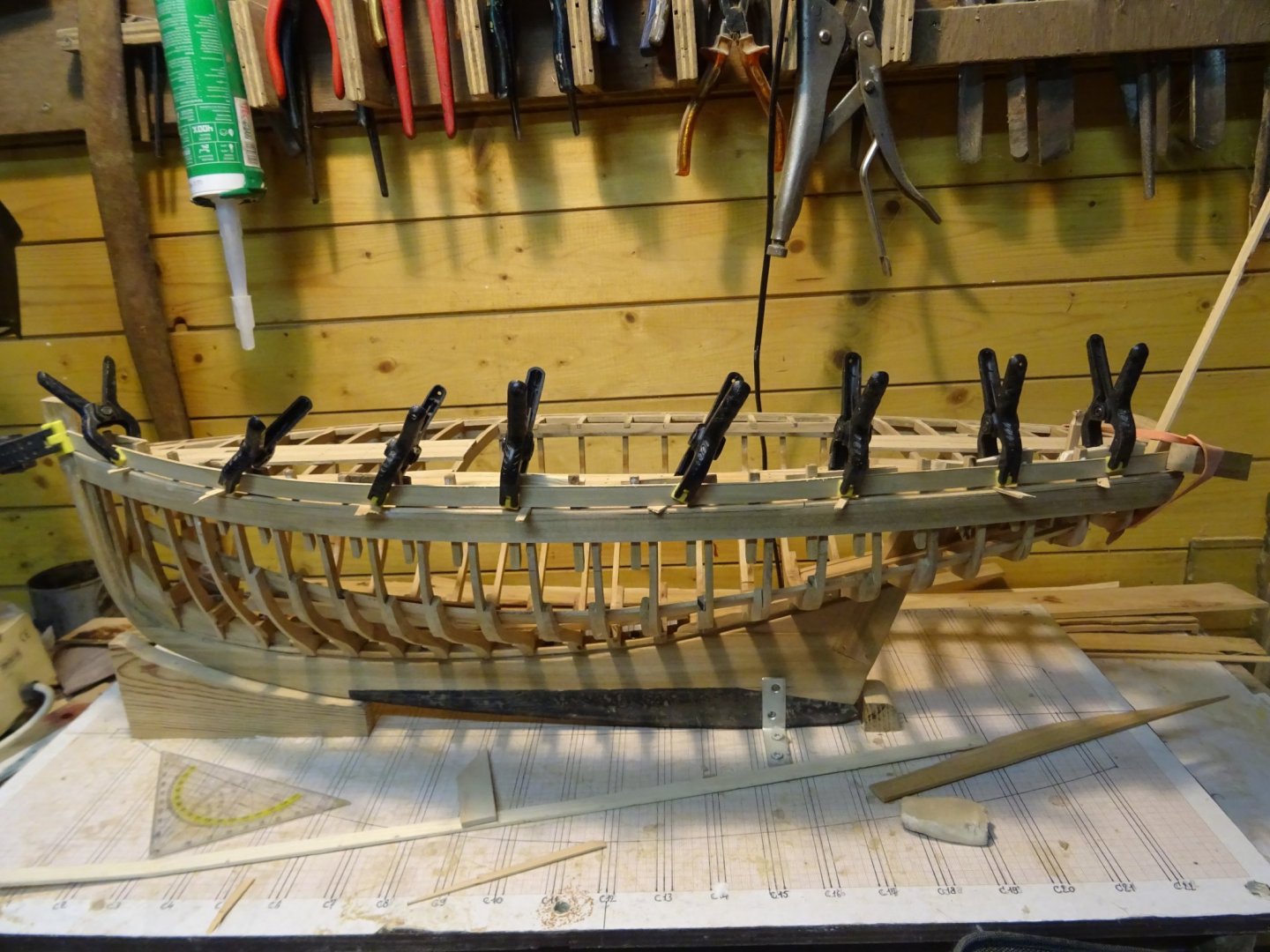
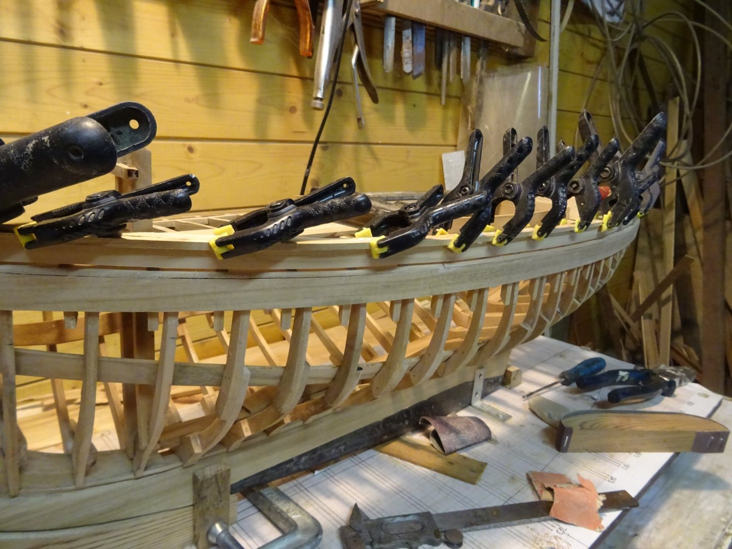
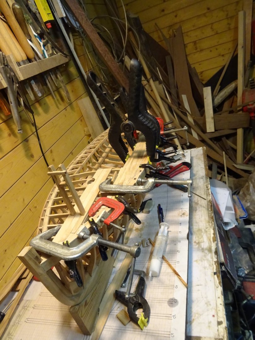
Gluing the rail plank. In between the rail and the waterway I put small wooden spacers to form the scuppers.

Cutting off the excesses of the stanchions.
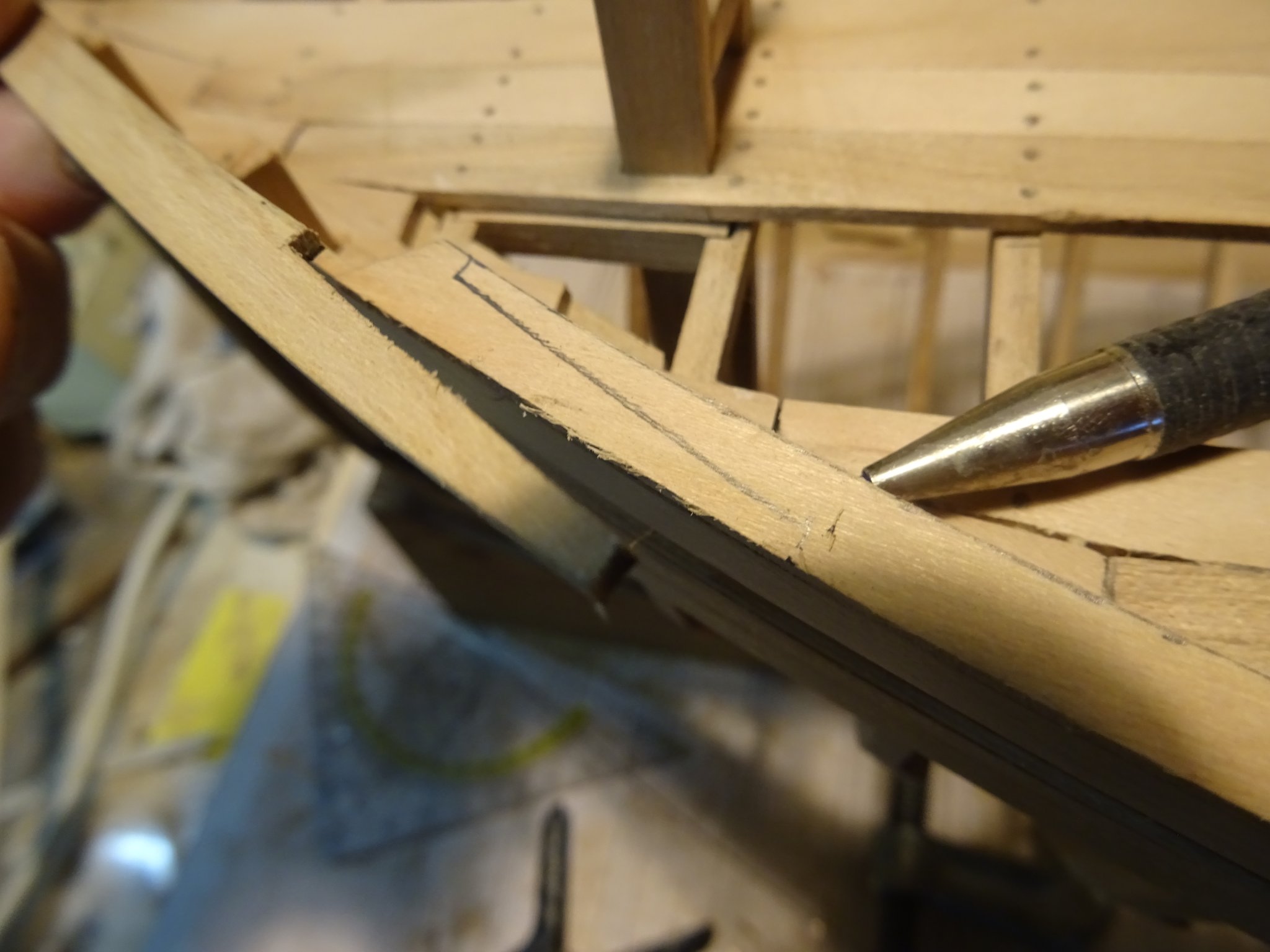
Making the gunwale: I trace the outer shape of the wale on the bottom of the plank from which I will saw the gunwale.
Sawing the outer bow of the gunwale.
The outer shape is sawn an sanded. Fitting it.
Now the inner edge is sawn and sanded also.

The whole gunwale consists of three parts.
The three parts have to be joined together to become one gunwale. Drawing the forward joint.
I use the vise also here to saw the joints.

Tracing over the shape of the joint on the neighbor piece of gunwale.


The joint.
Gluing the whole gunwale.
Sanding the gunwale even with the wale.

I glue a thin frame on the outside of the gunwale.
And also one on the inside. When the glue is dry the edges of the lists are rounded off with sand paper. At the positions of the stanchions the gunwale is tree nailed with the stanchion.
Thank you for reading
Thank you to follow
Thank you for the likes
and thank you for your constructive comments,
Till next week
- FriedClams, GrandpaPhil, oneslim and 12 others
-
15
-
14.4 The boat hook
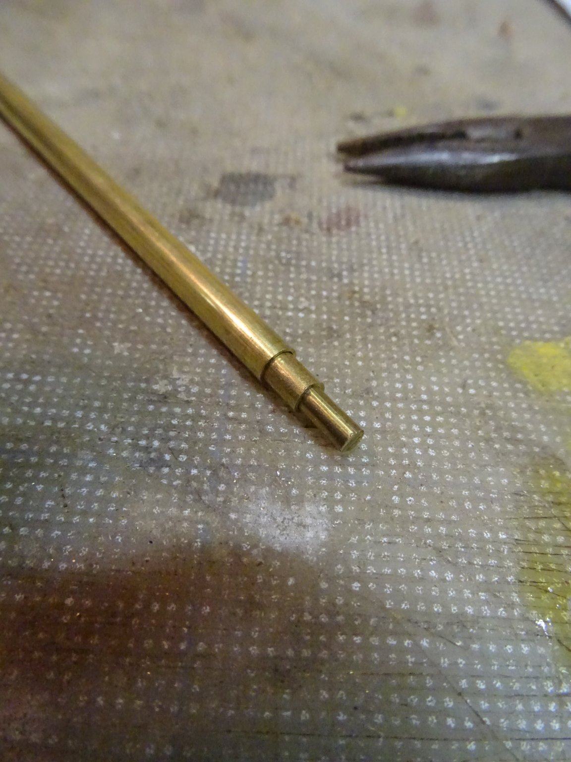
To make the make the boat hook, I use a brass rod and two brass tubes with different diameters which can slide in each other telescopically.

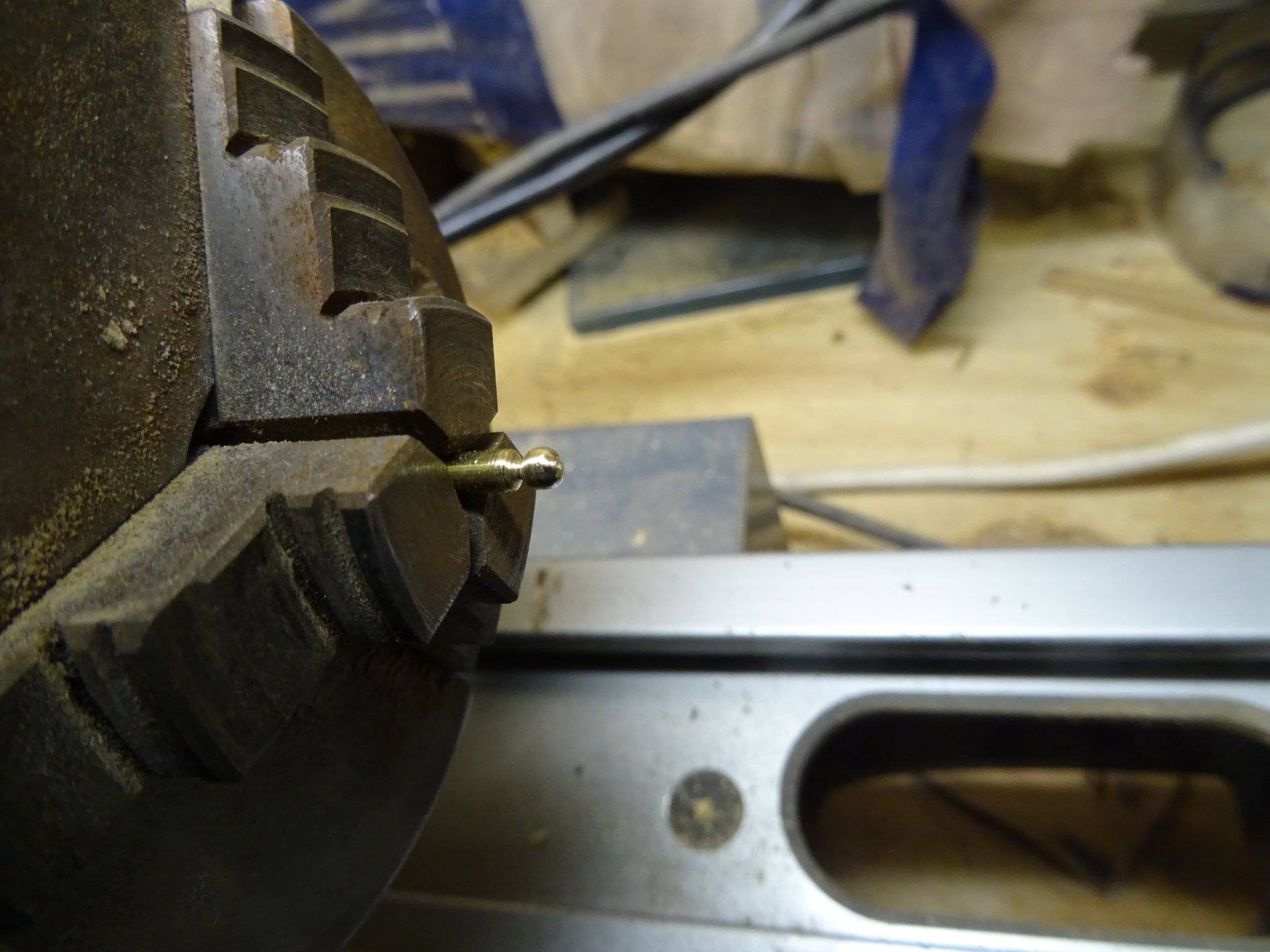
I turn a globule on the top of the rod.
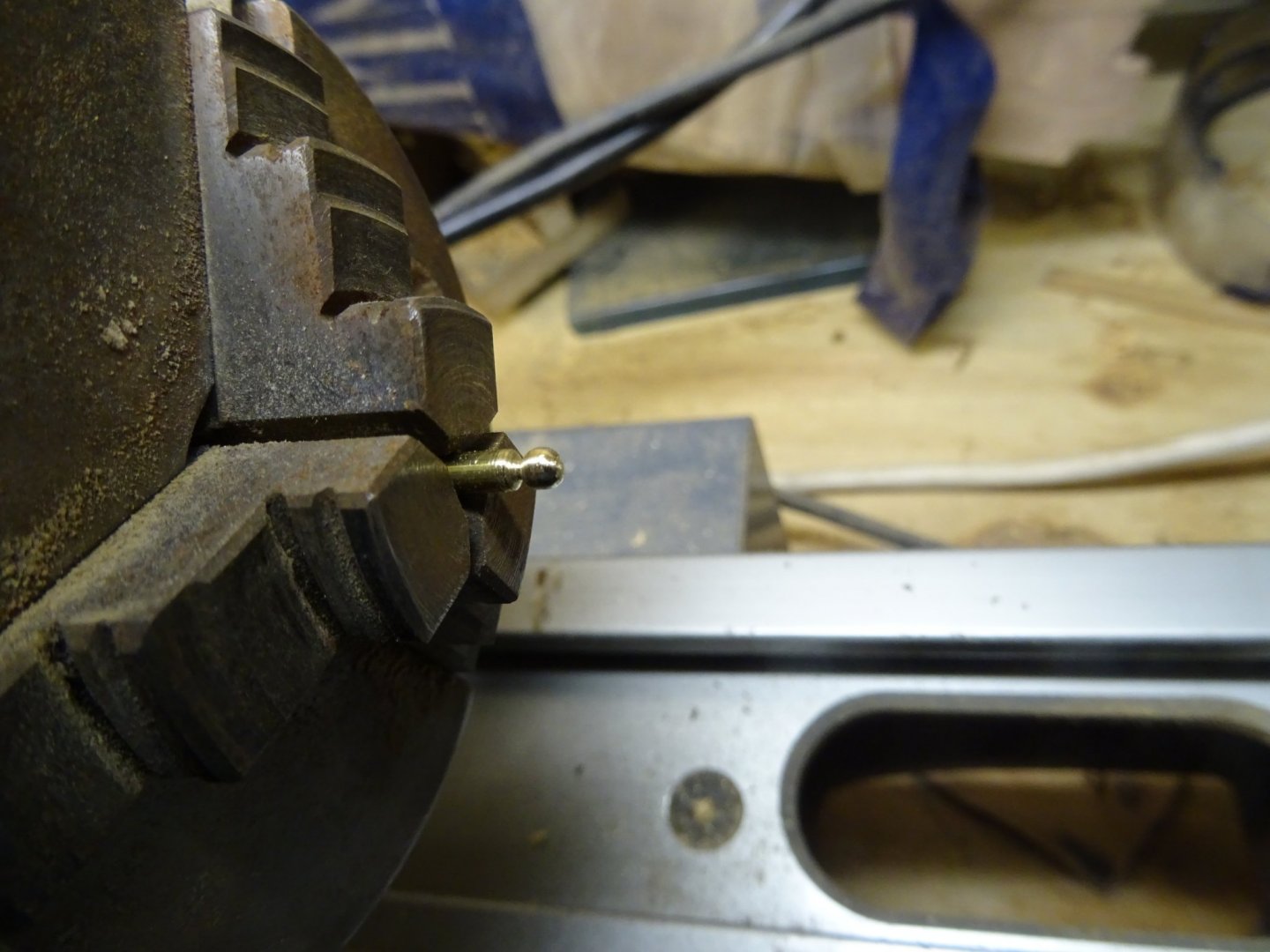
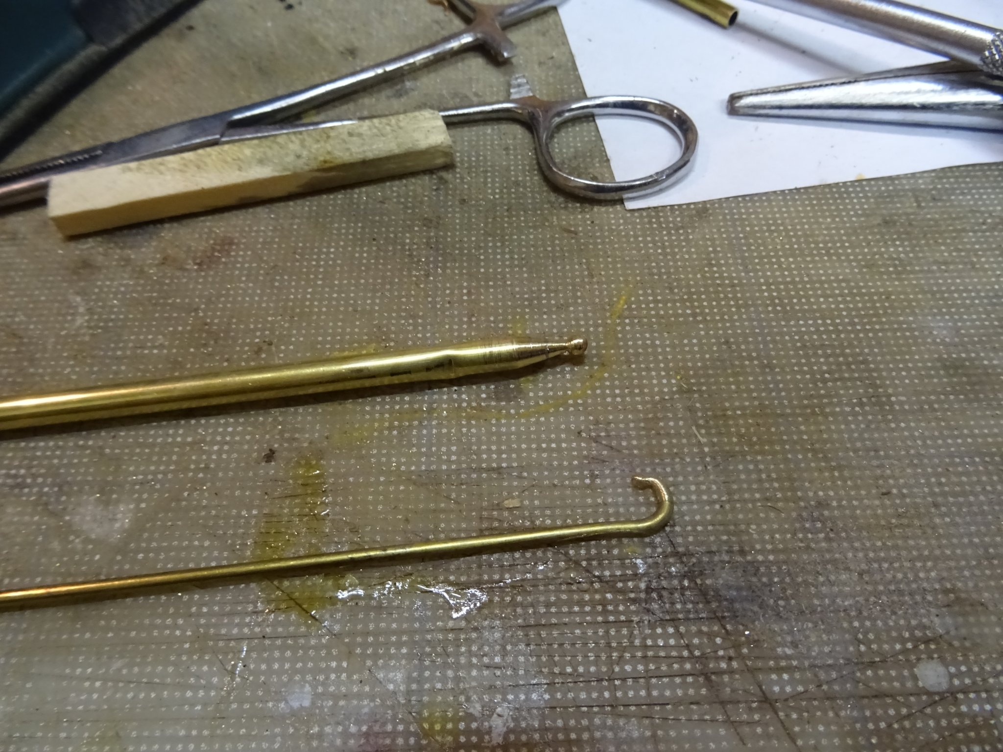
Then I slide the whole again in each other like on the first picture and solder them. They go again on the lathe to turn them off conically. I file also the hook on a smaller brass rod.
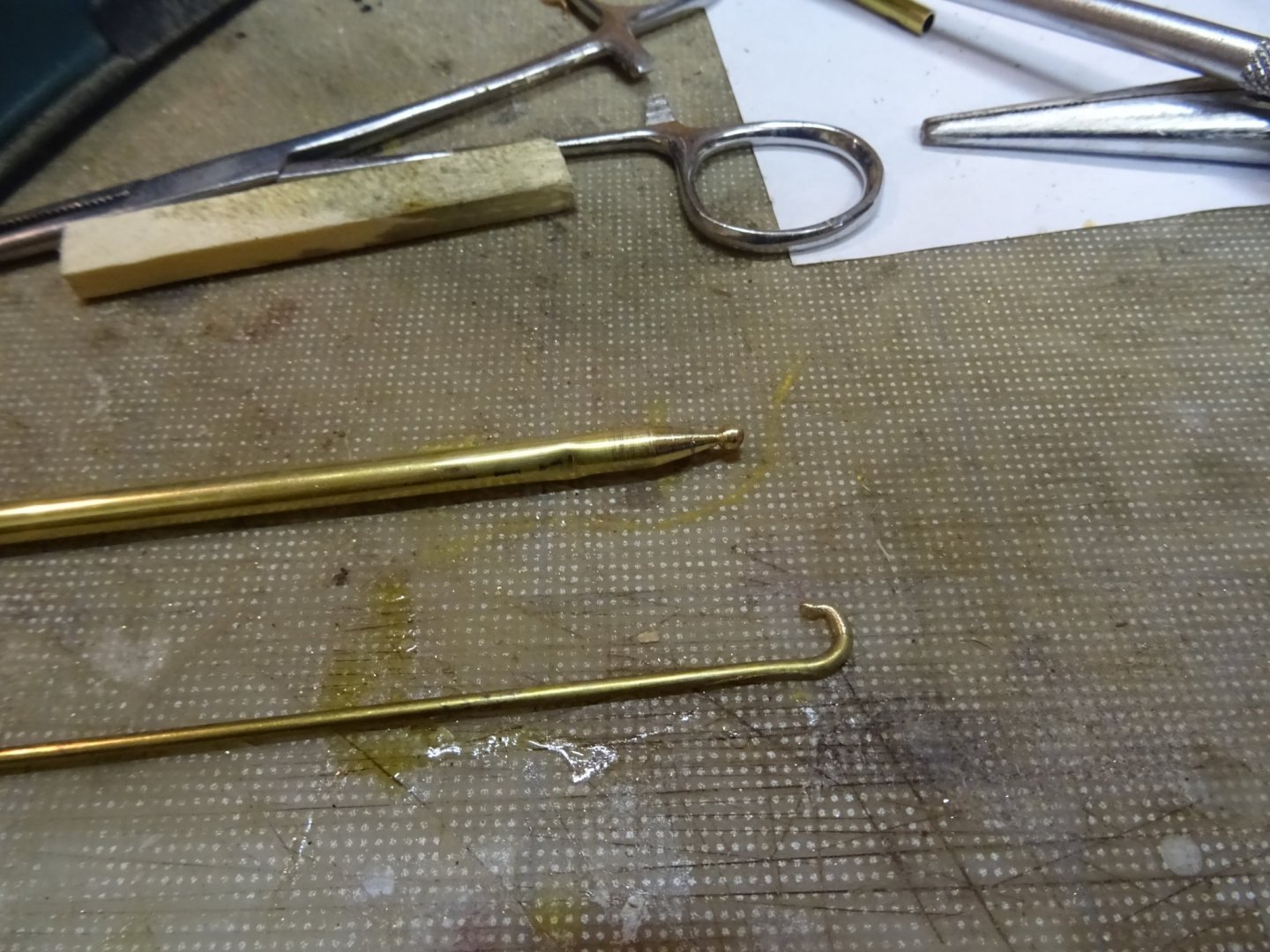
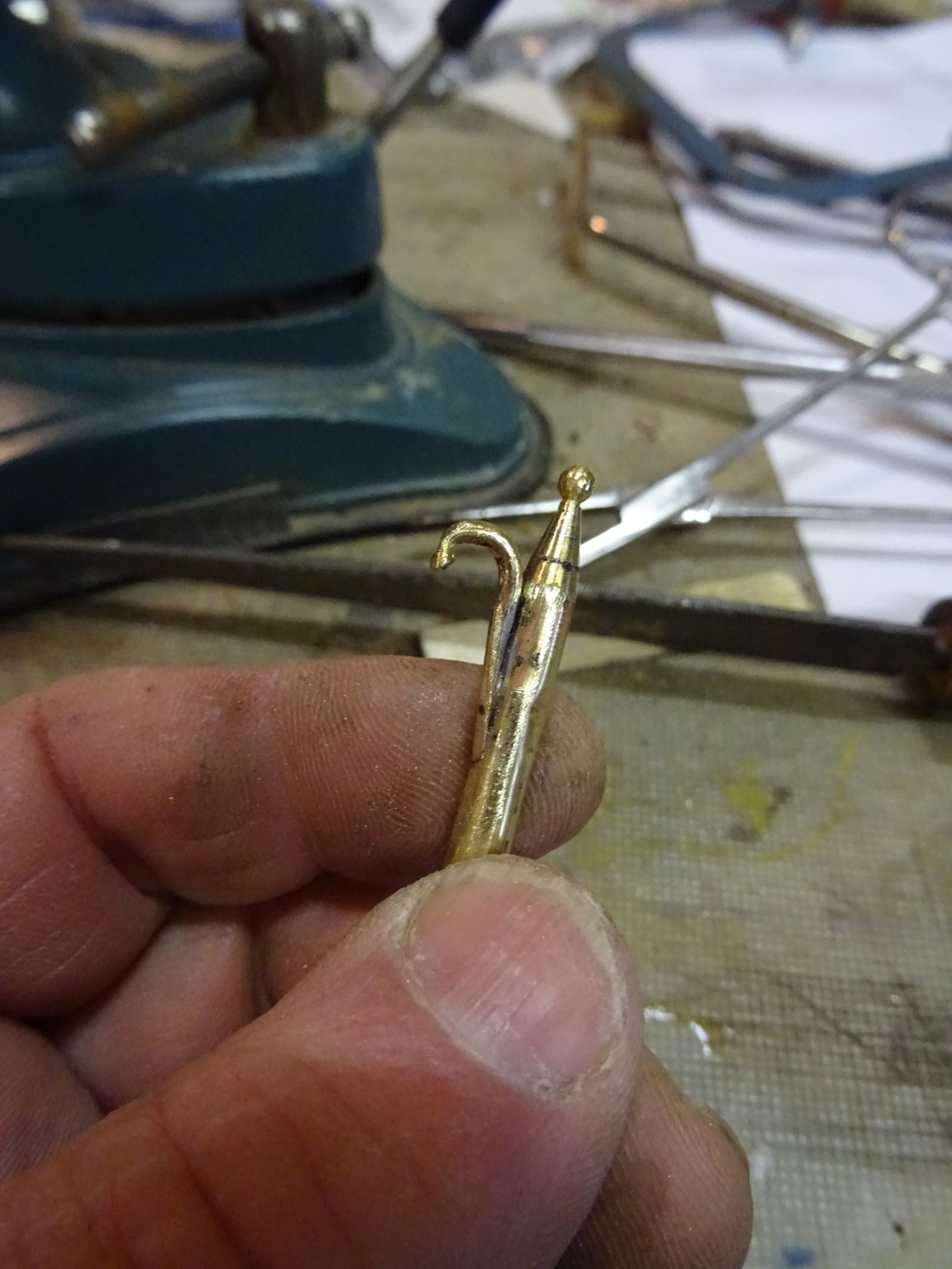
The hook is soldered on the top.
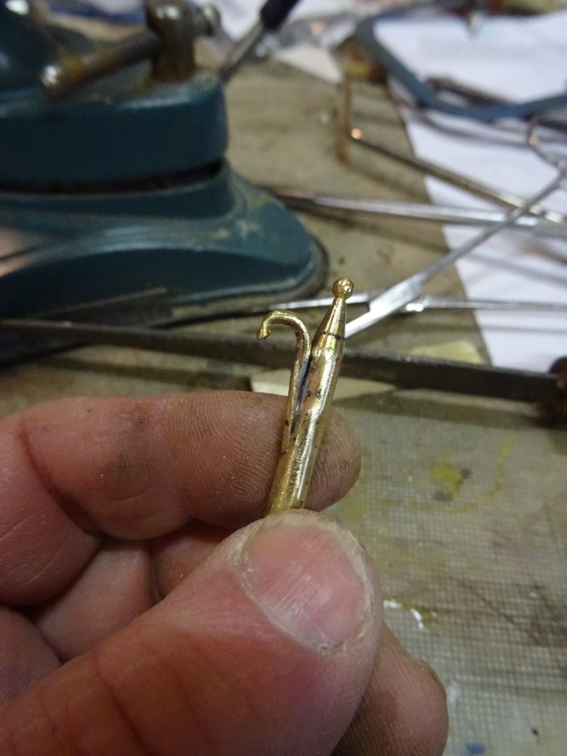
I make the stock from a piece of pear wood.


The assembled boat hook.
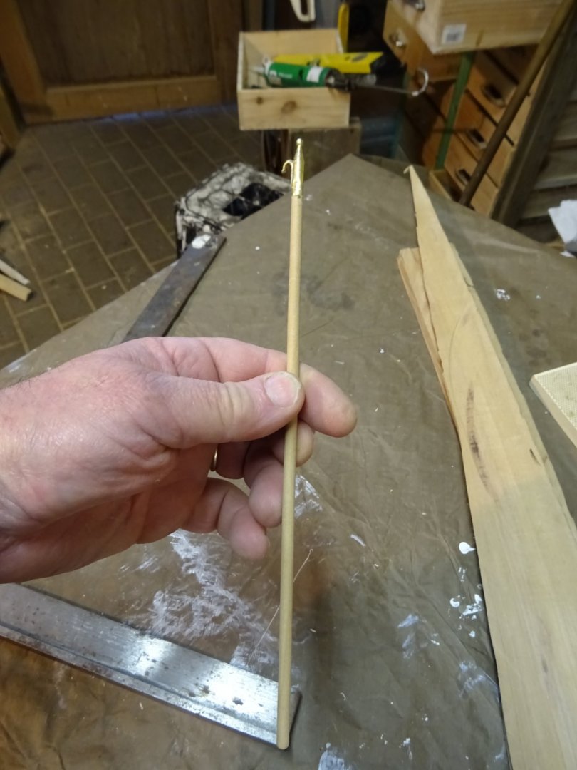
The hook is now varnished and ready for use in the boat.

-
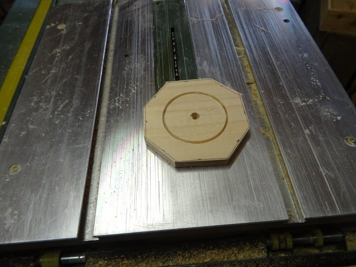
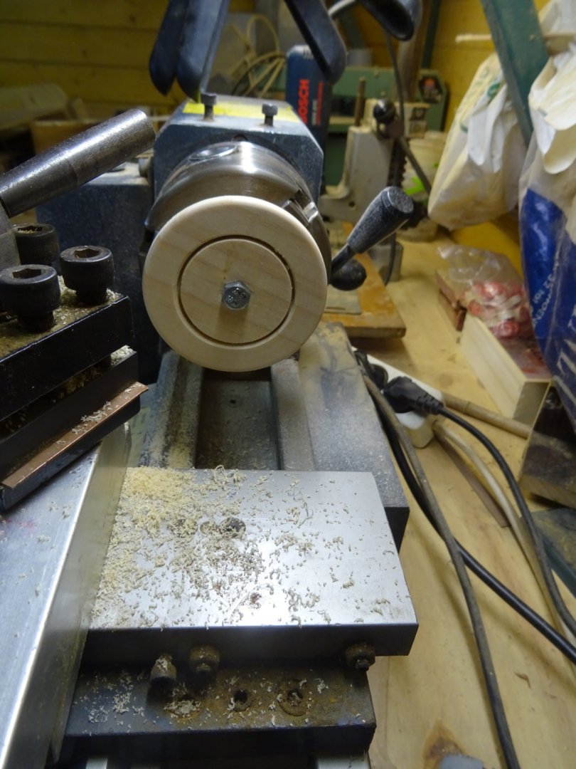
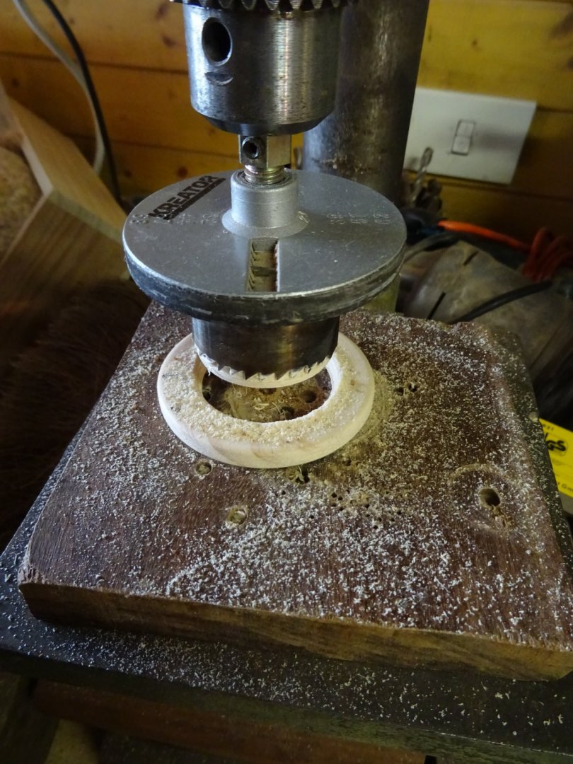
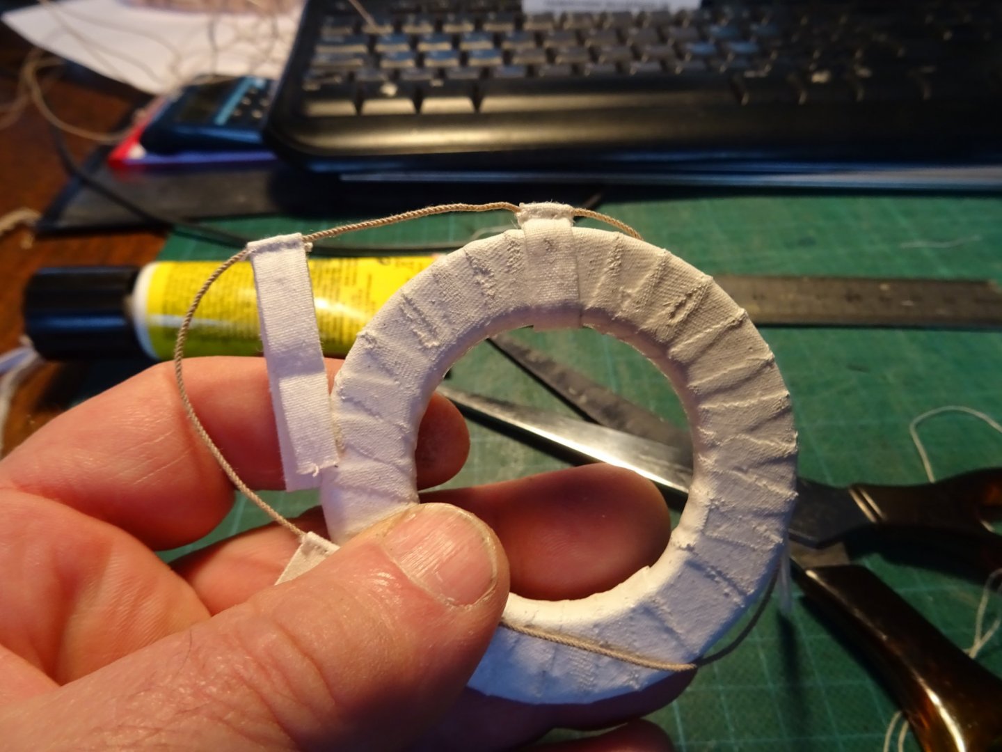
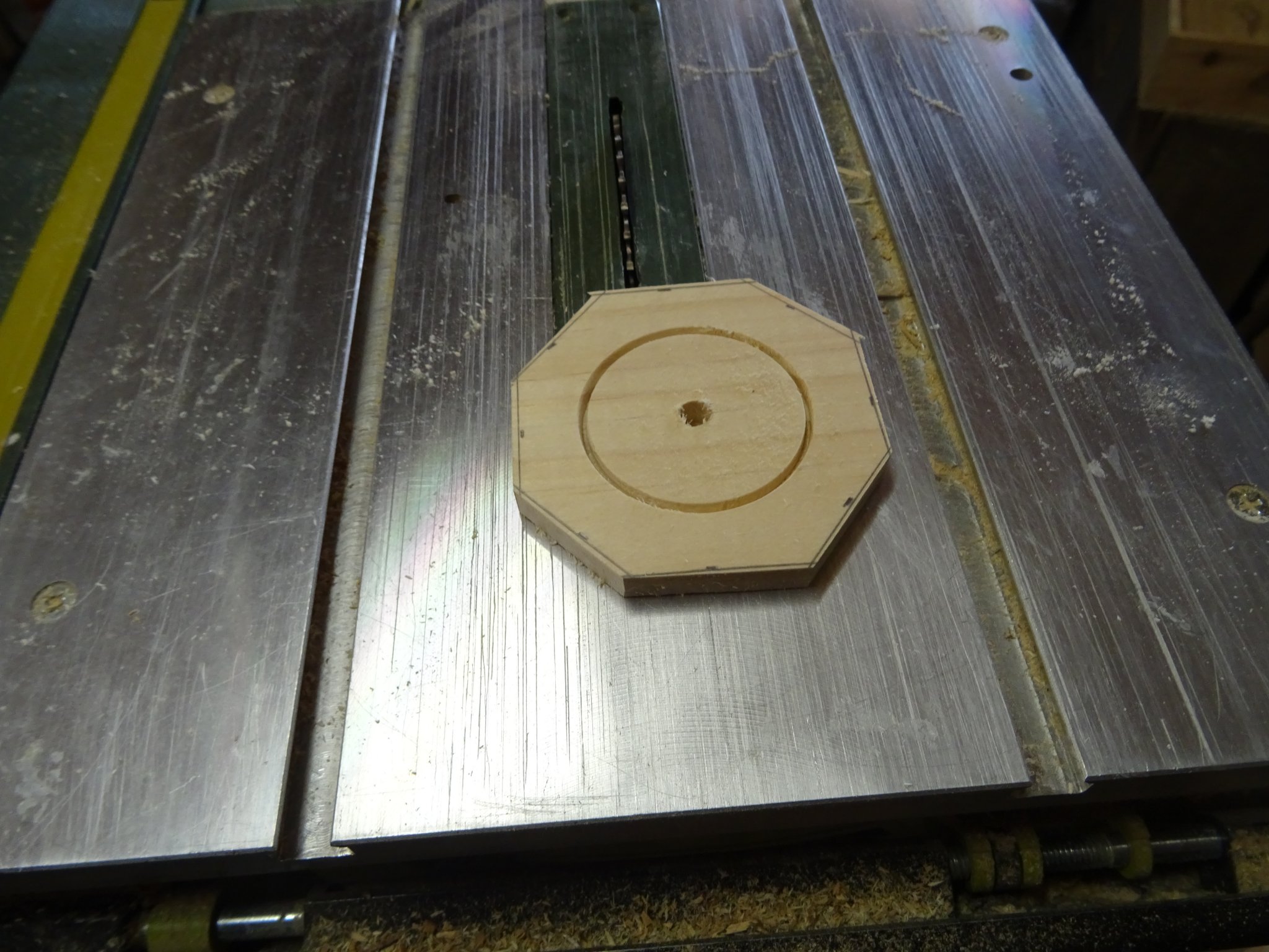
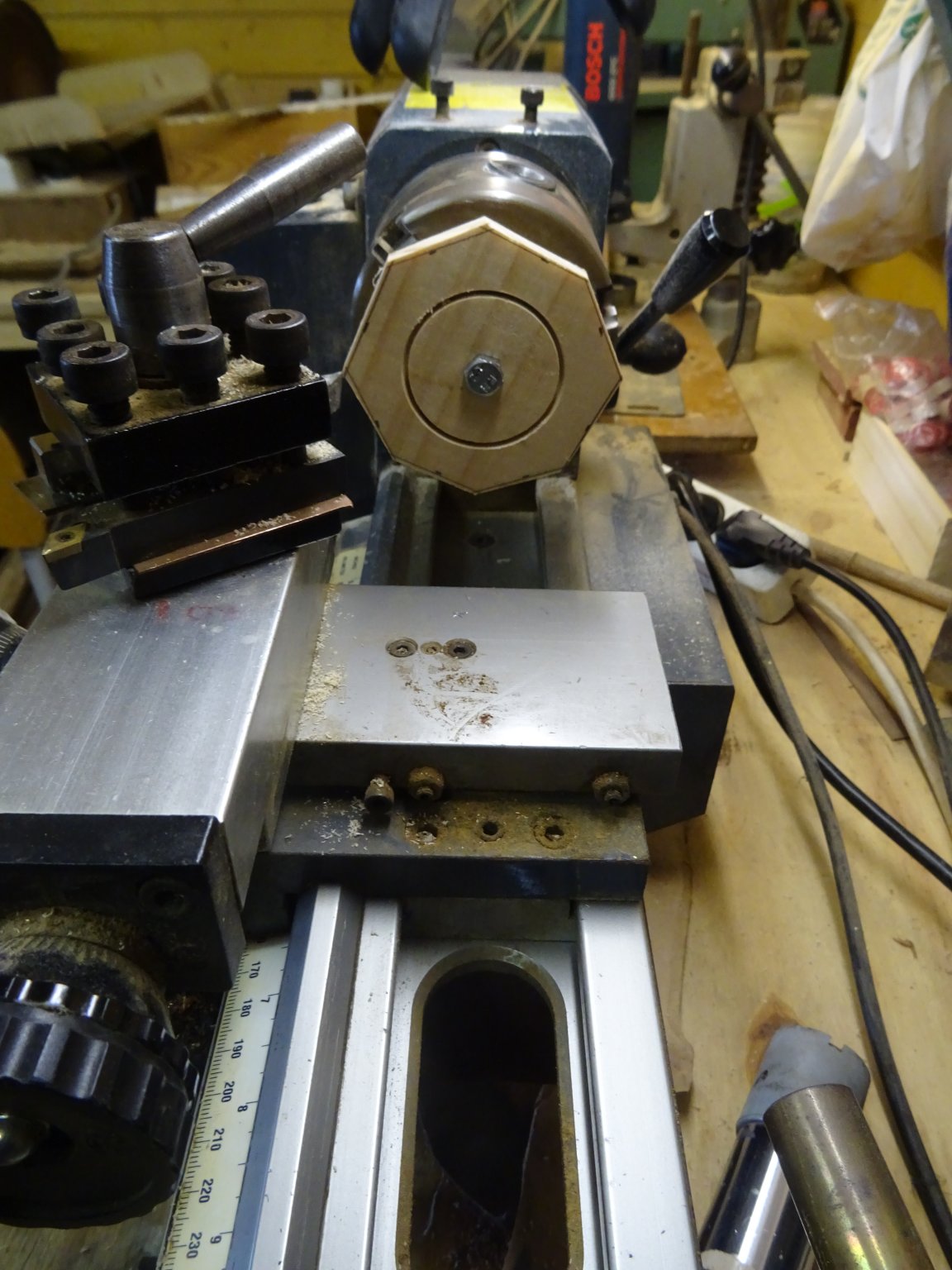
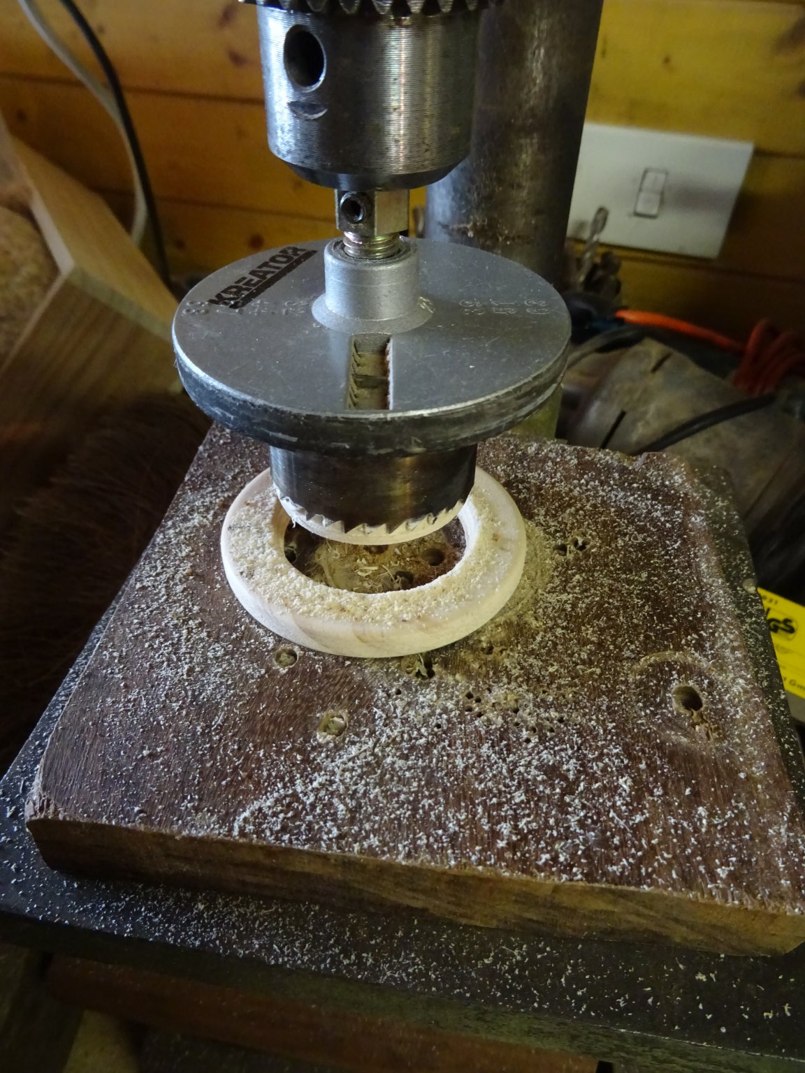
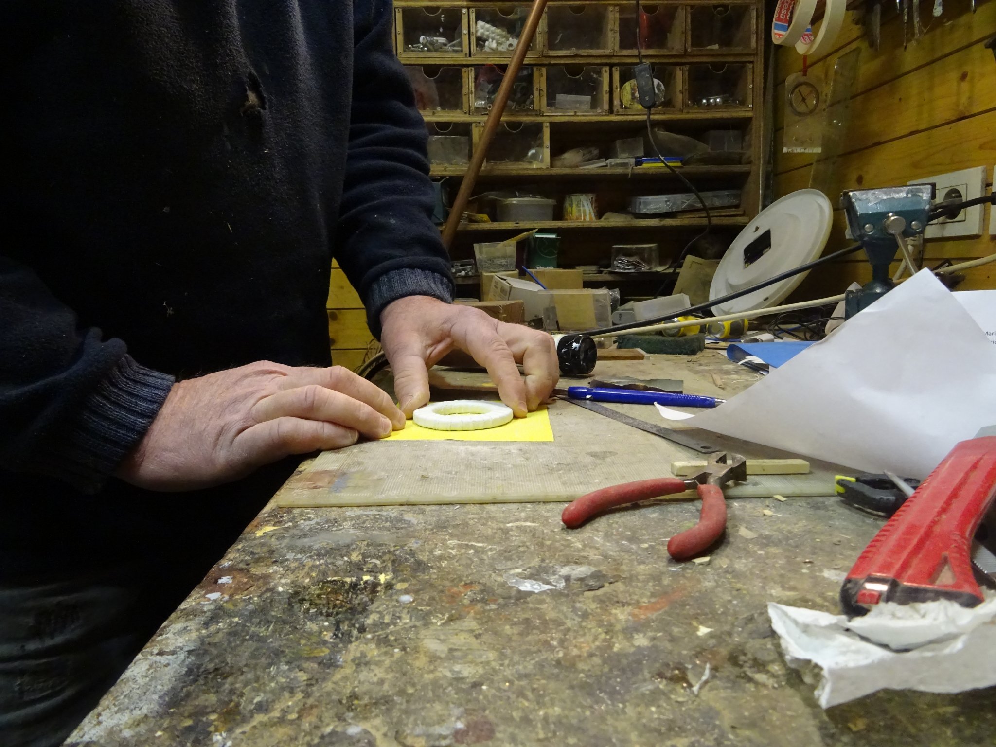
14.3 The life belt
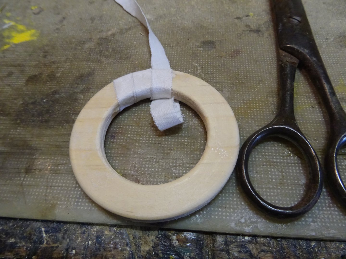
To make the lifebuoy, I start with making a wooden ring.


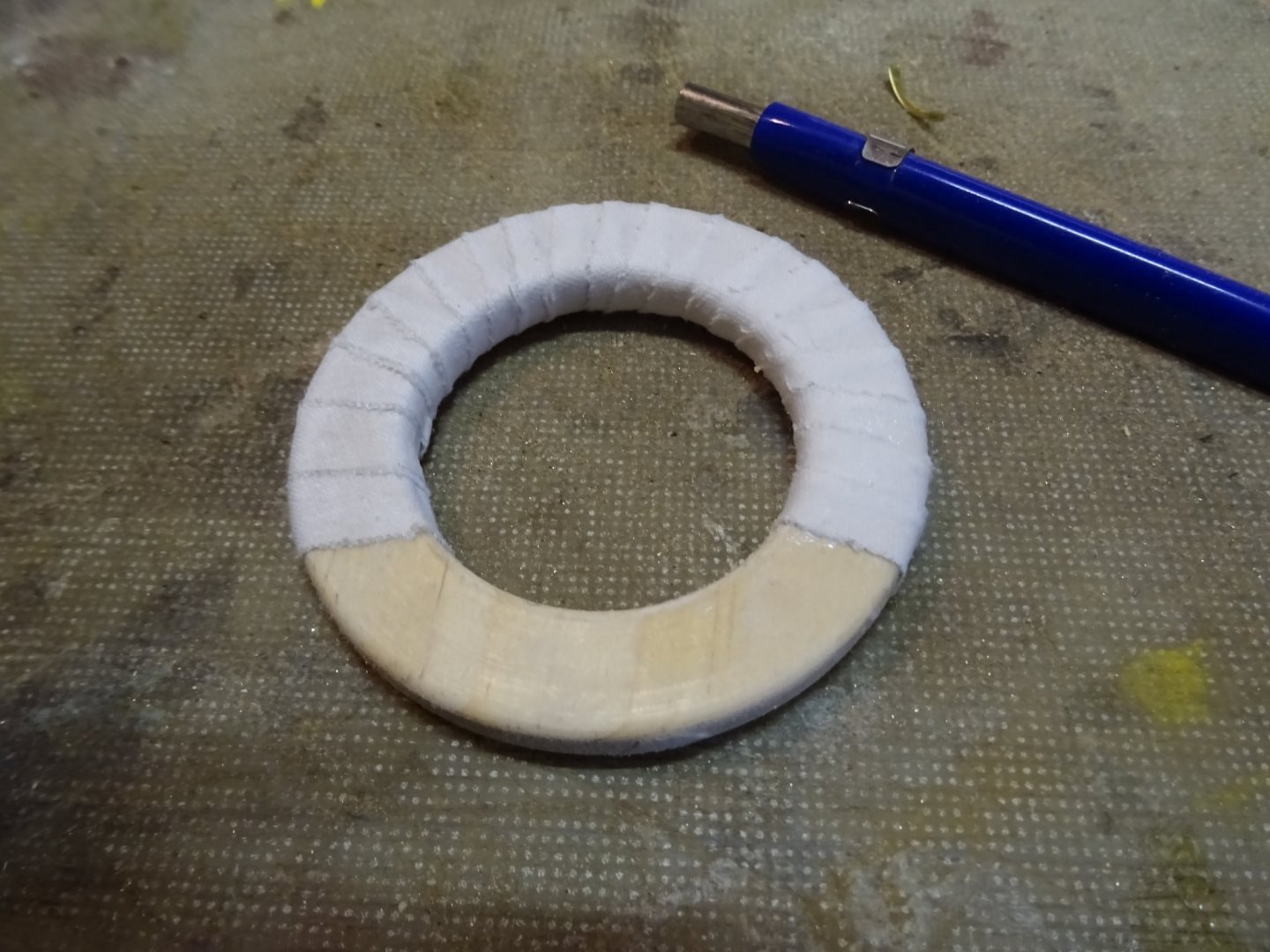
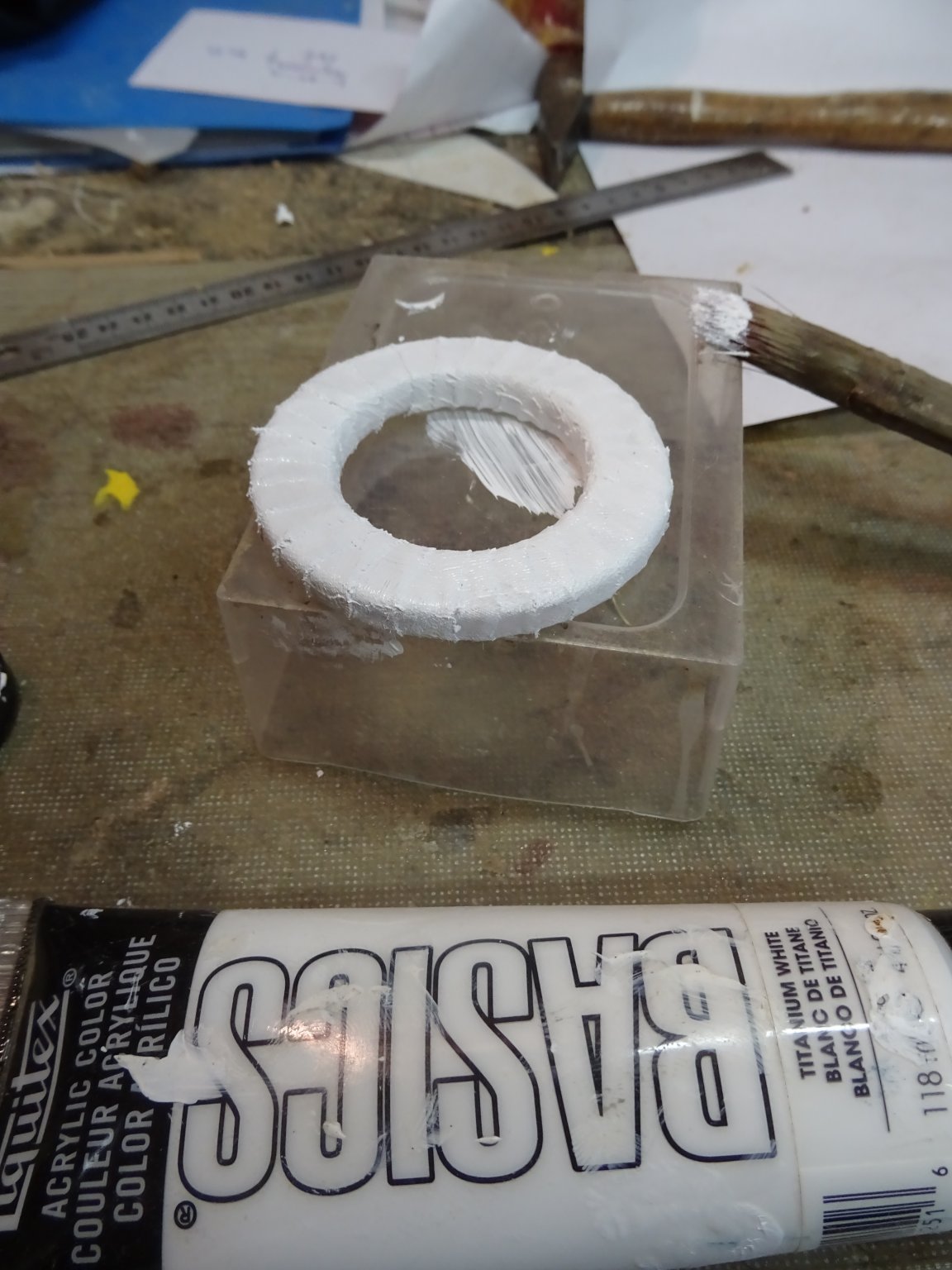
To give it a canvas look, I wrap and glue the ring with a strip of cotton.
Then I paint it in white
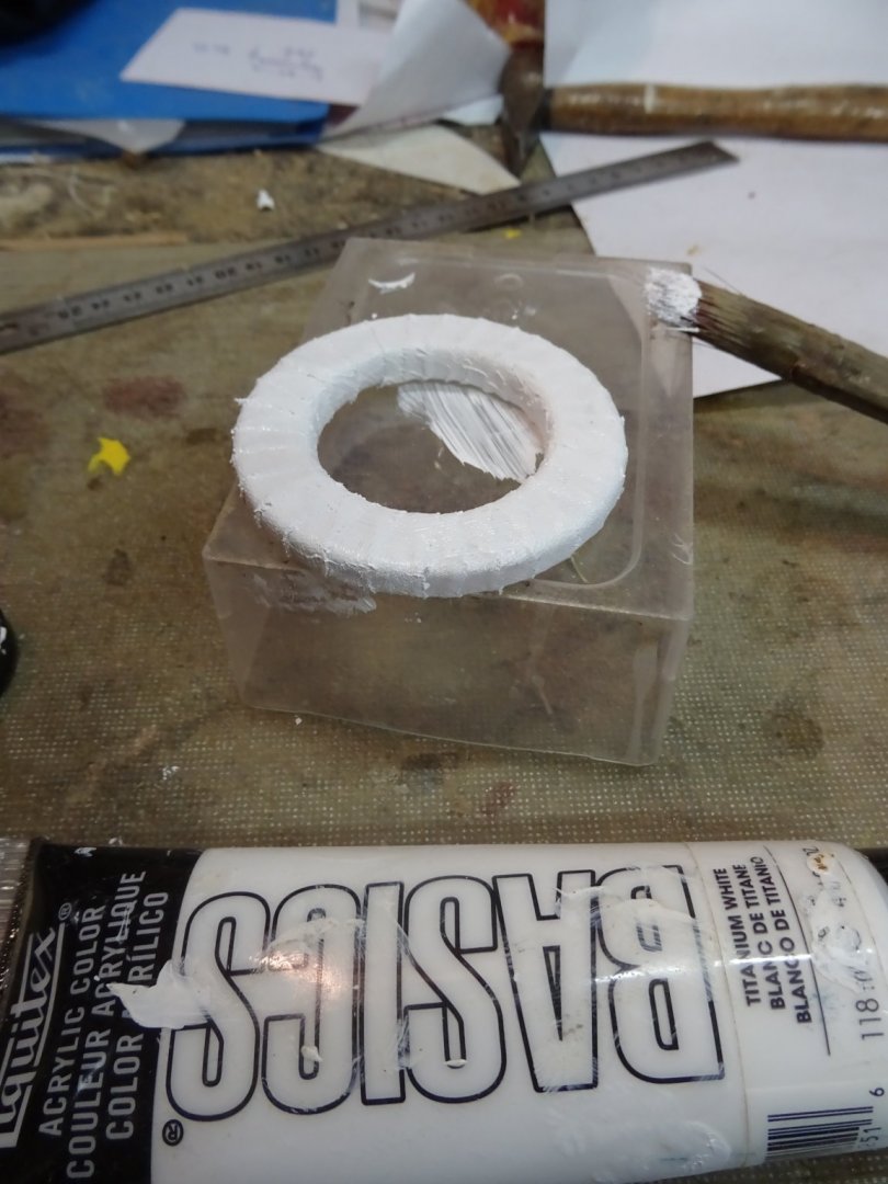
It has two layers of paint. Between each layer I sand it lightly with sanding paper. On top comes a coat of varnish

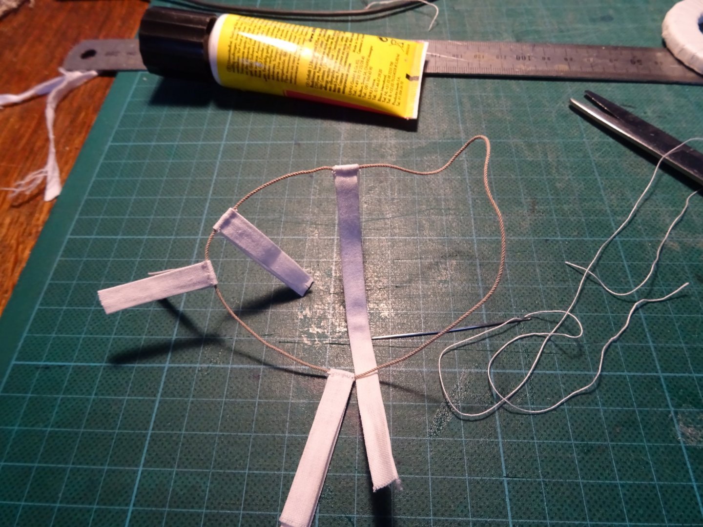
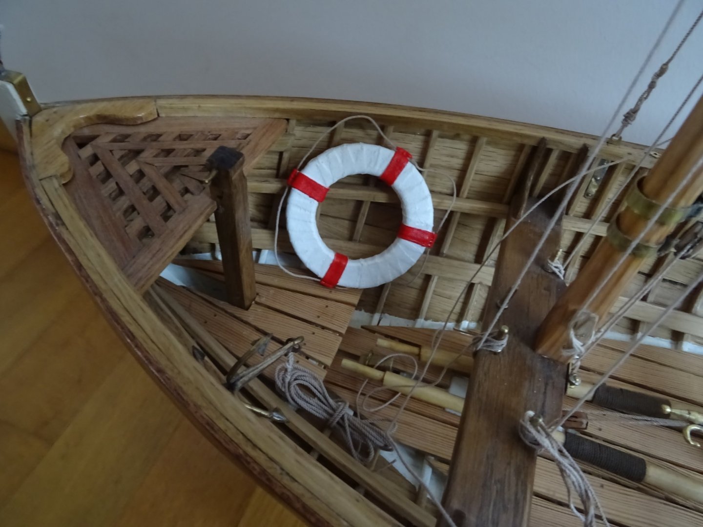
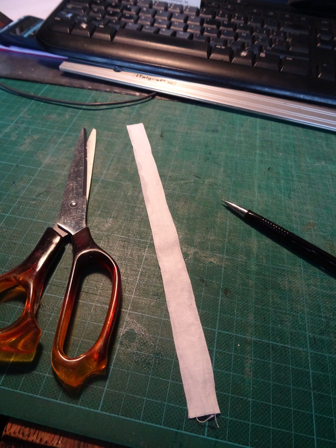
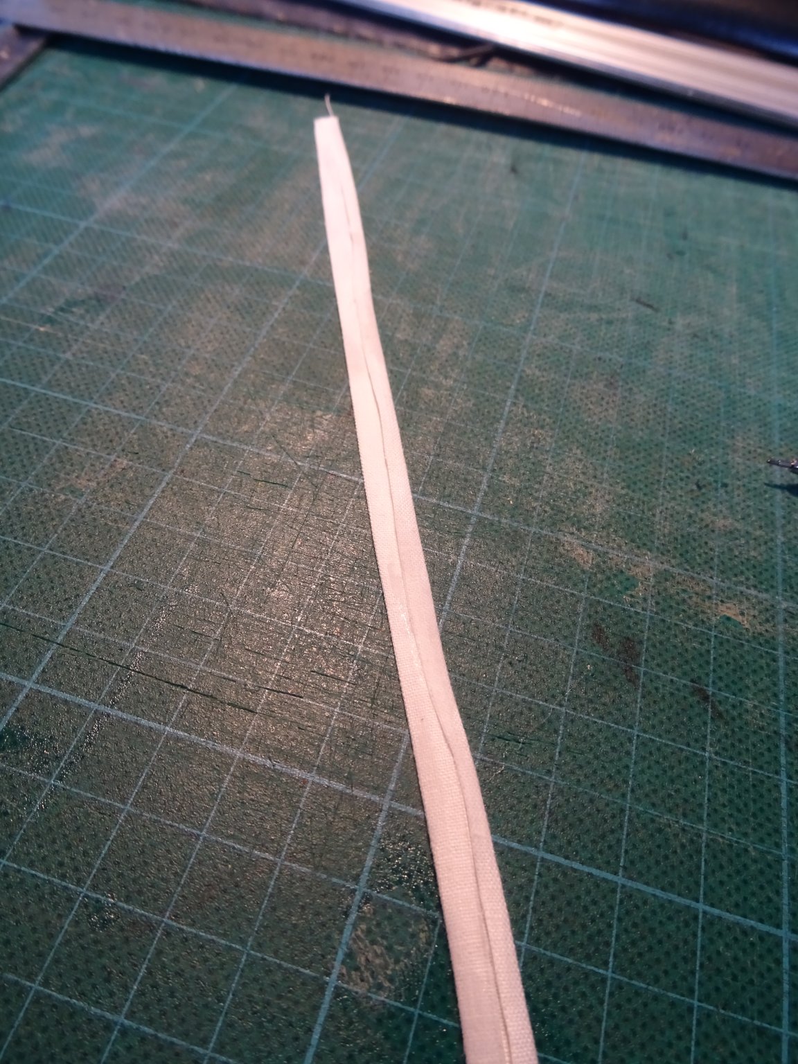
On the buoy come four canvas rings at which a line is sewed. The rings are made of cotton strakes of which I ply over the sides to the middle.


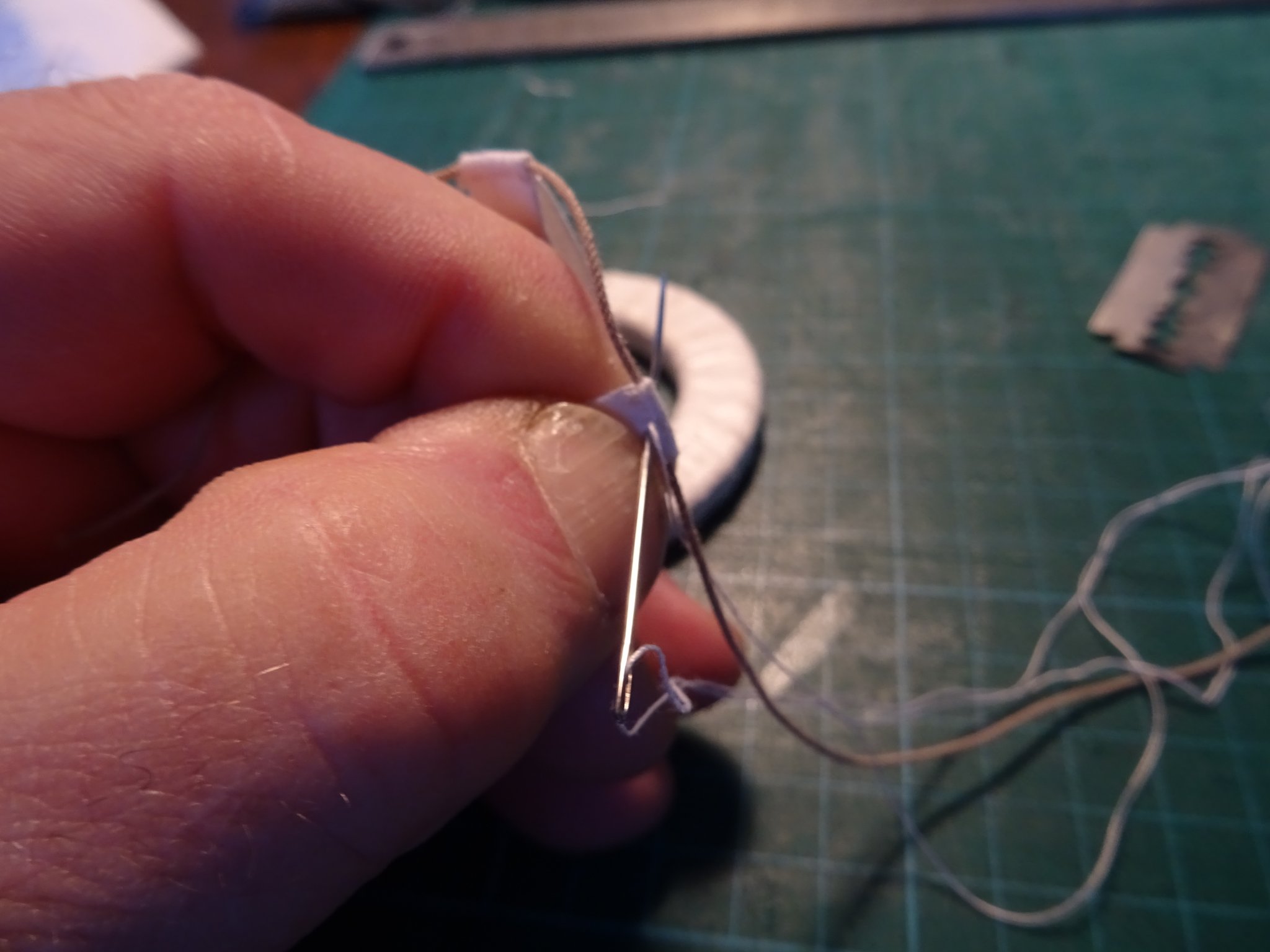
Next is sewing the line in the rings.

I glue the rings on the buoy ...
... and paint them red. And my boat is ready for a 'man over board'.
- Retired guy, druxey, FriedClams and 7 others
-
10
-
-
-
15 hours ago, Moab said:
Wow, Wow, Wow! If I could meke oars like yours I'd become a professional Oar maker and market my services. Just beautiful. Adding the walnut is spectacular and the tackle rope is beautiful. I keep learning what REAL CRAFTSMANSHIP is all about...Moab
Thanks Moab!
A little while ago I received the suggestion in this forum to become seamstress, now you want me to become oar maker. I think that I prefer to remain 'pensionado'⛱️. Gives me more time for non-profit modeling.
- paulsutcliffe and mtaylor
-
2
-
23 hours ago, Mark Pearse said:
Hello Geert
I have just seen this log - what a beauty, & the way you have built the model is just great. Especially well done on the sails.
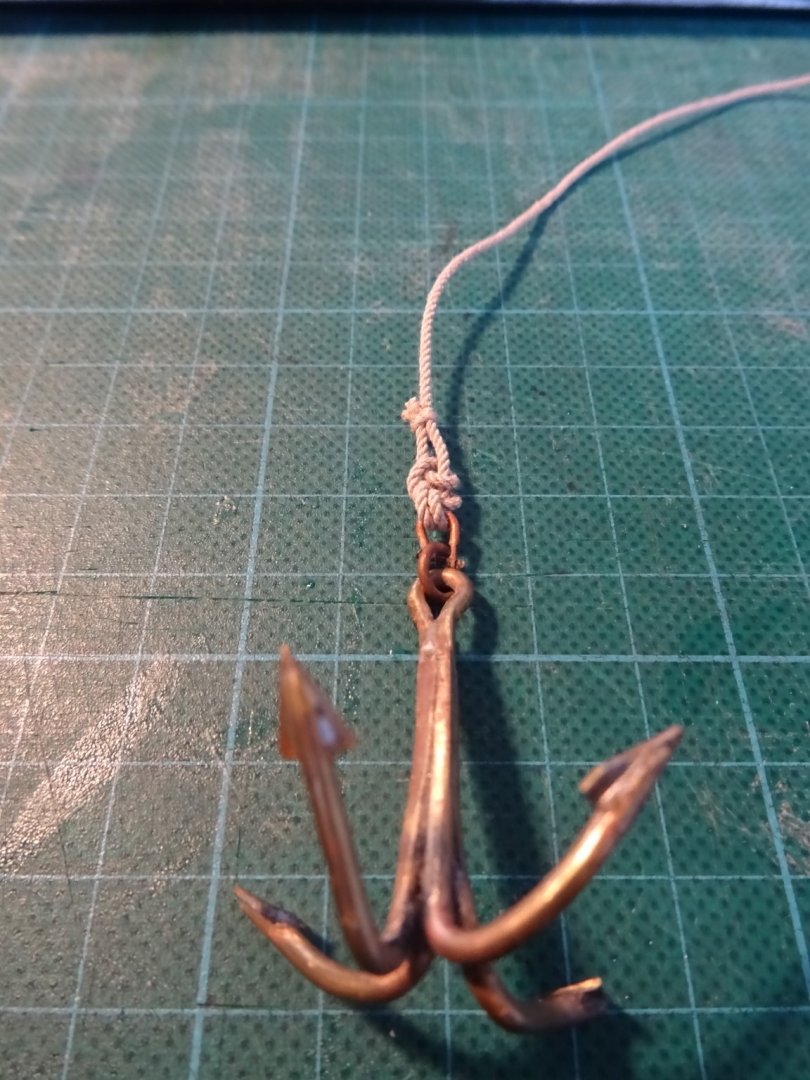
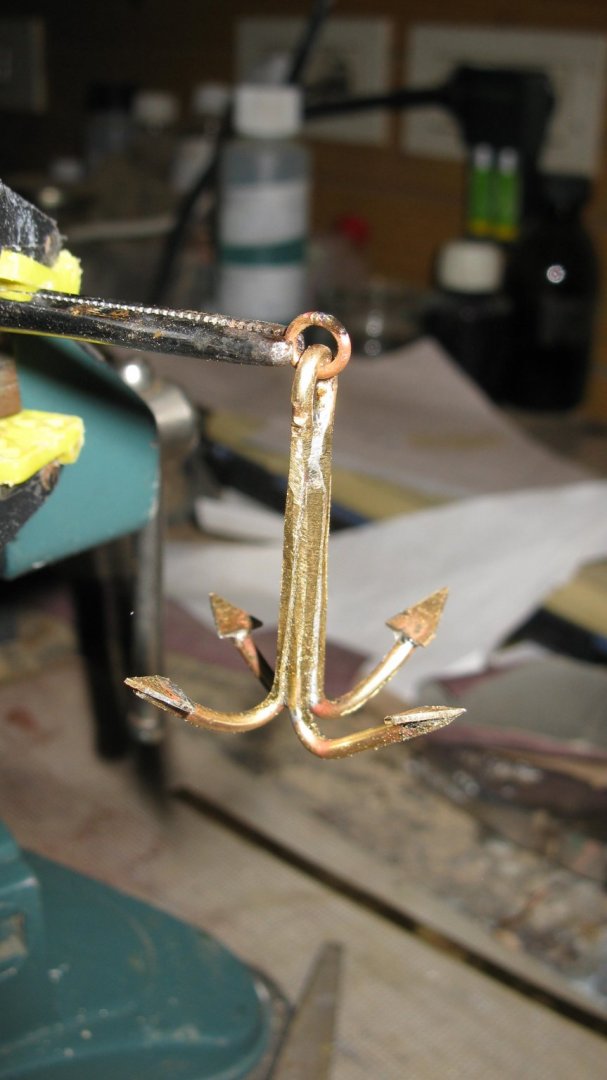
Is that the sort of anchor commonly used there?
Mark
PS: The gaff bridle discussion was very interesting. I think the arrangement as drawn would put too much compression on the spar. Gaff spars can bend under load & some of that is fine, but if you have some bend plus compression it would break much more easily than if the compression wasn't there. I think the change suggested would solve it.
Thanks for your kind words, Mark.
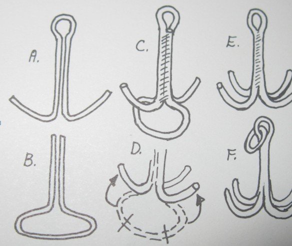
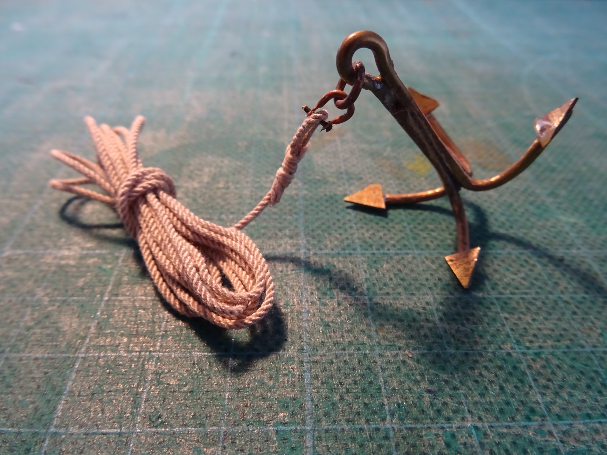
A boat's grapnel is often used in small boats to go at anchor for a short while. But in most cases it are grapnels with folding arms which can be stowed away easily on board. My choice for that sort of anchor is inspired by the fact that I am not such an experienced metal worker and I found a very easy build description for it in the book 'To Build a Whaleboat' by Erik A.R. Roonnberg.
- Mark Pearse, mtaylor and cog
-
3
-
-
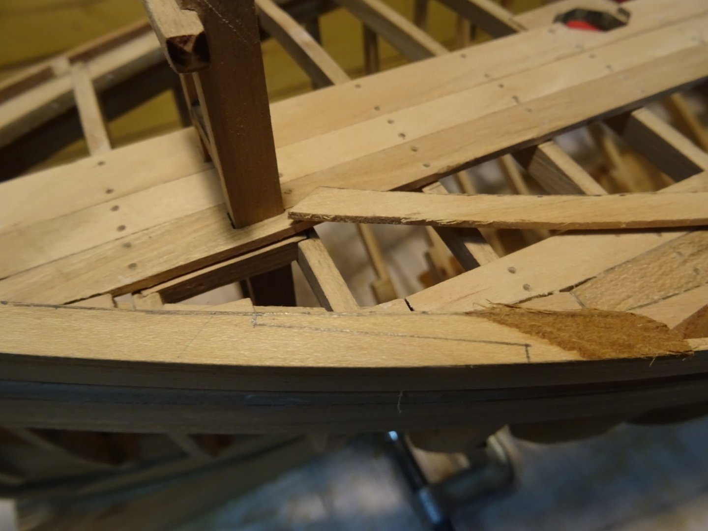
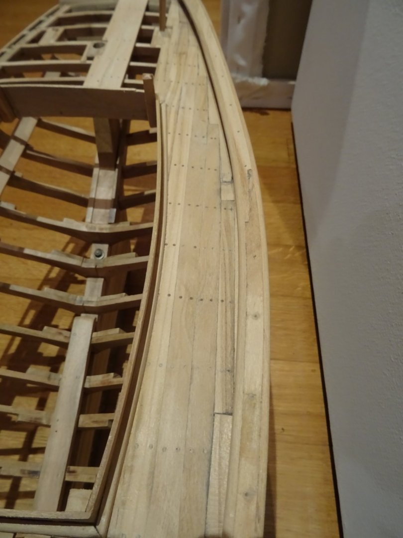
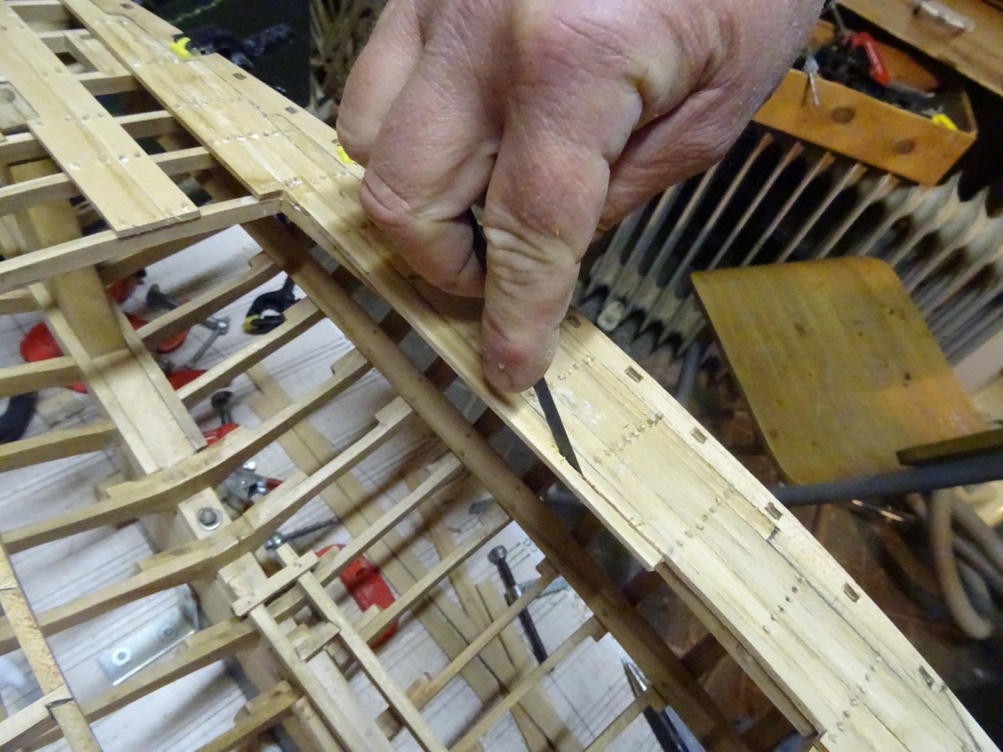
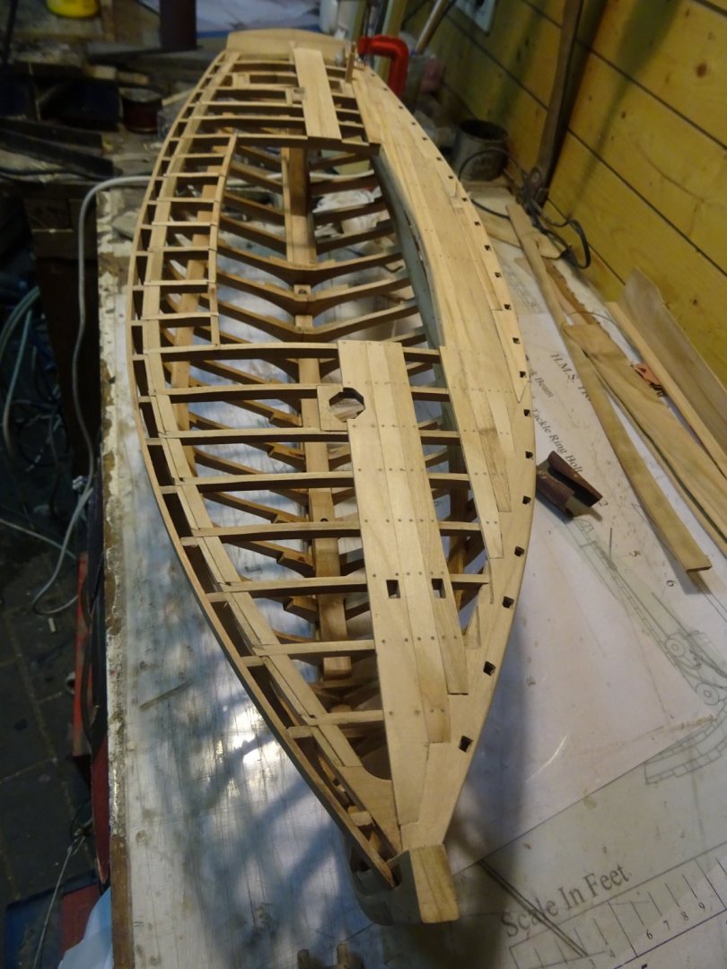
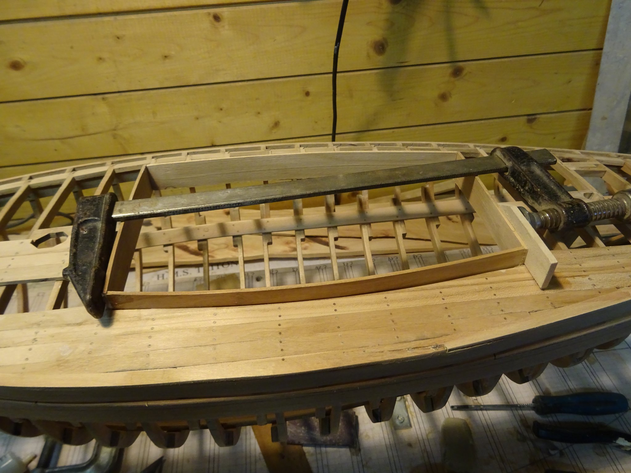
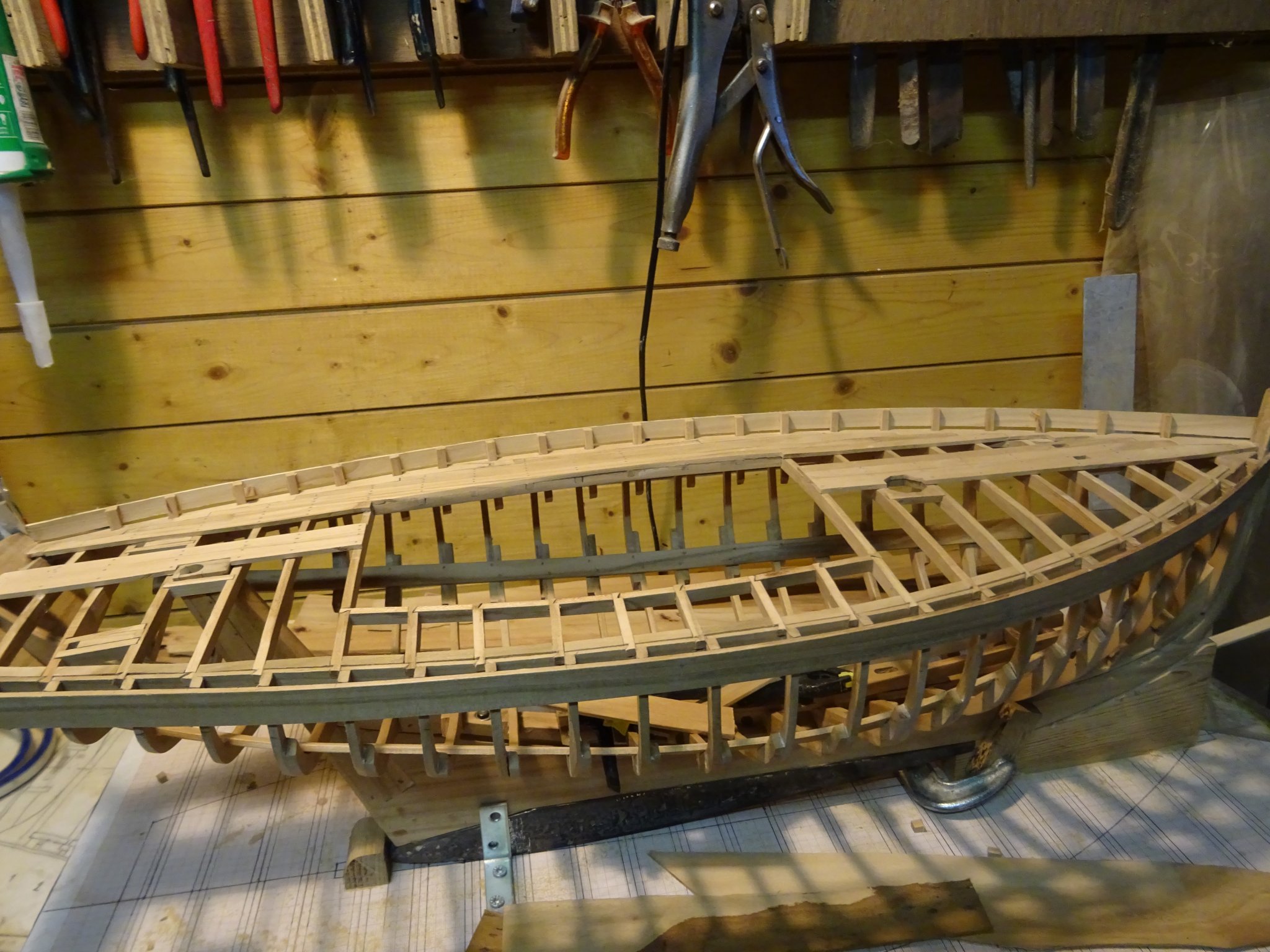
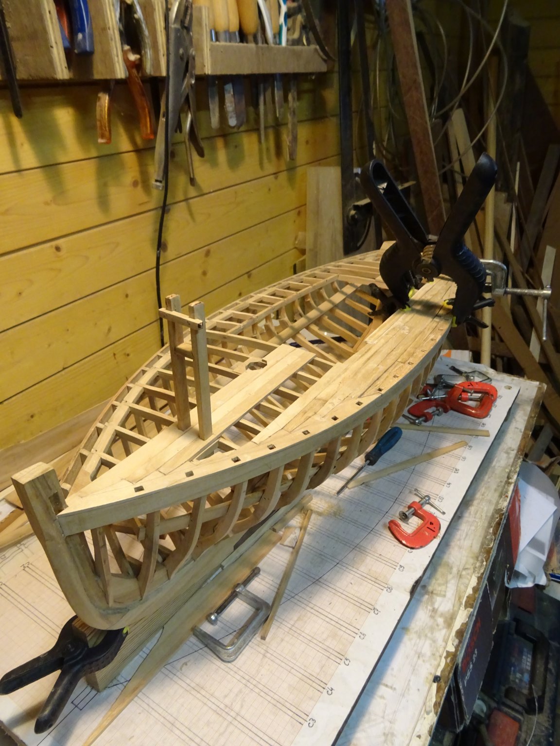
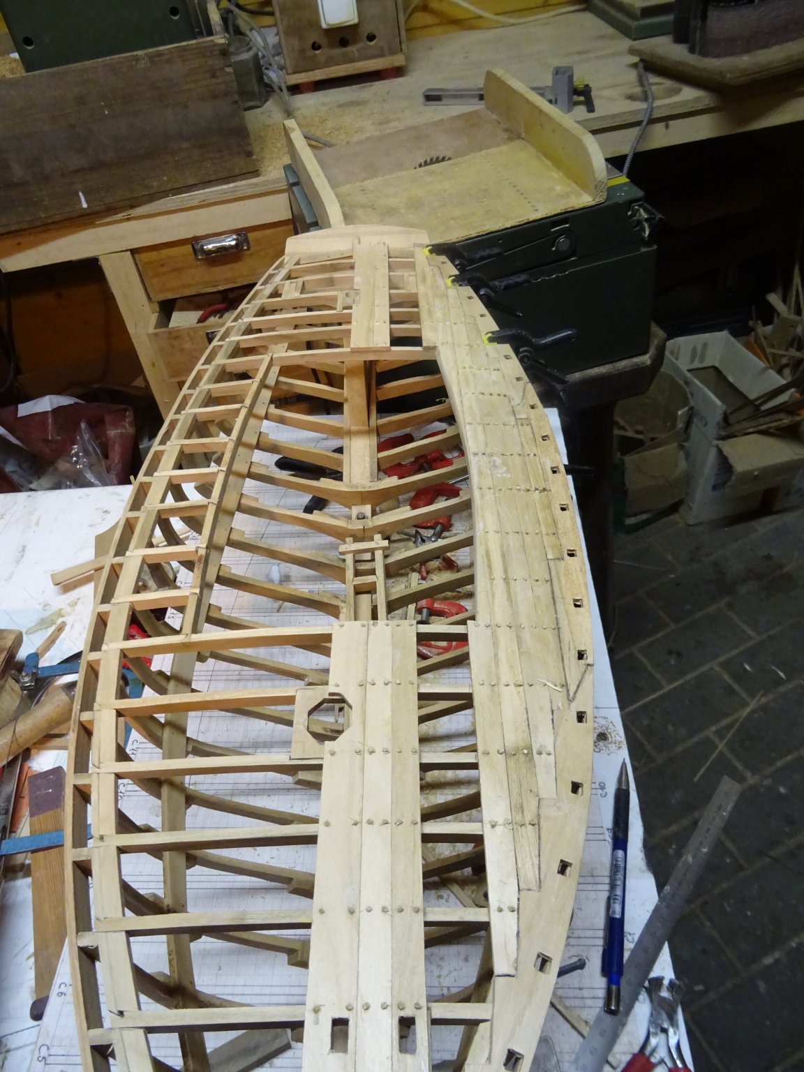
Starting to plank the deck. The aim is to make a dissected ship model, therefore I will only plank a part of the port side of the deck.
I begin with the middle plank on the forecastle.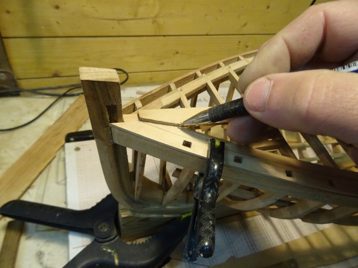
One plank follows the other (The riding bitts will not be as high as shown in the pictures. They are not fully pushed down). I 'overplank' the carling of the cockpit, what is too much will sawn off later.


Once again: this will be an dissected model, so that will be all for the deck planking.

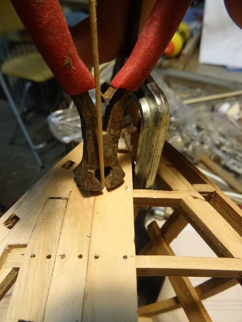
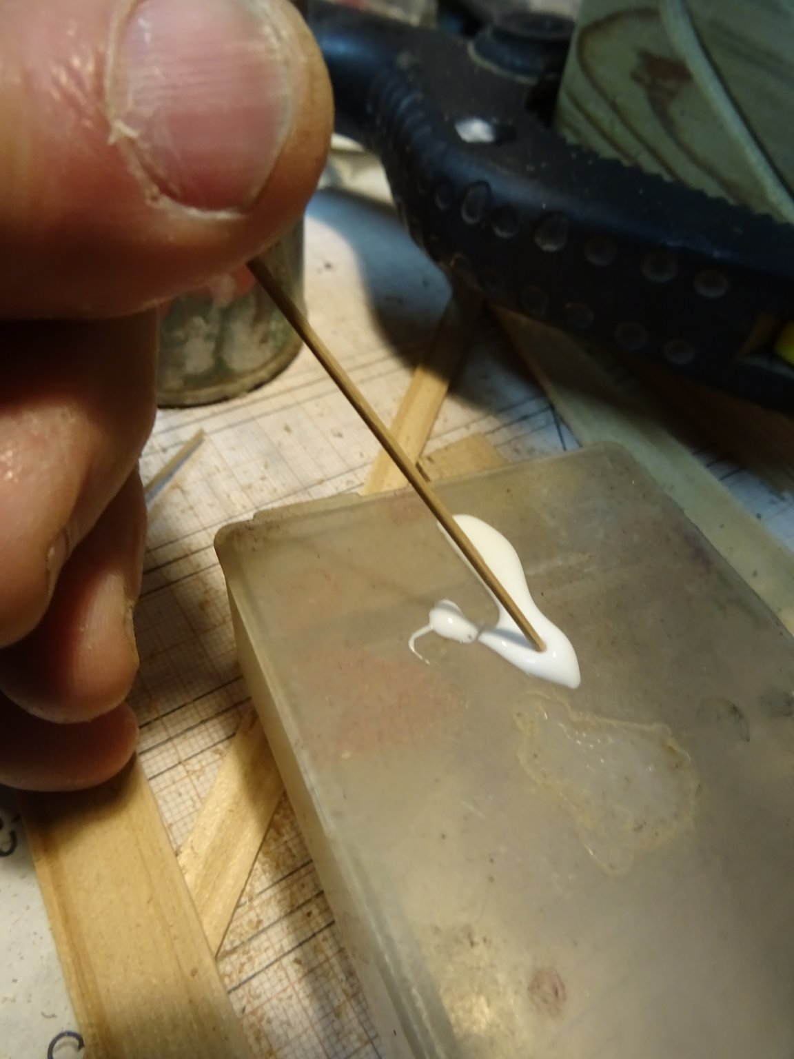
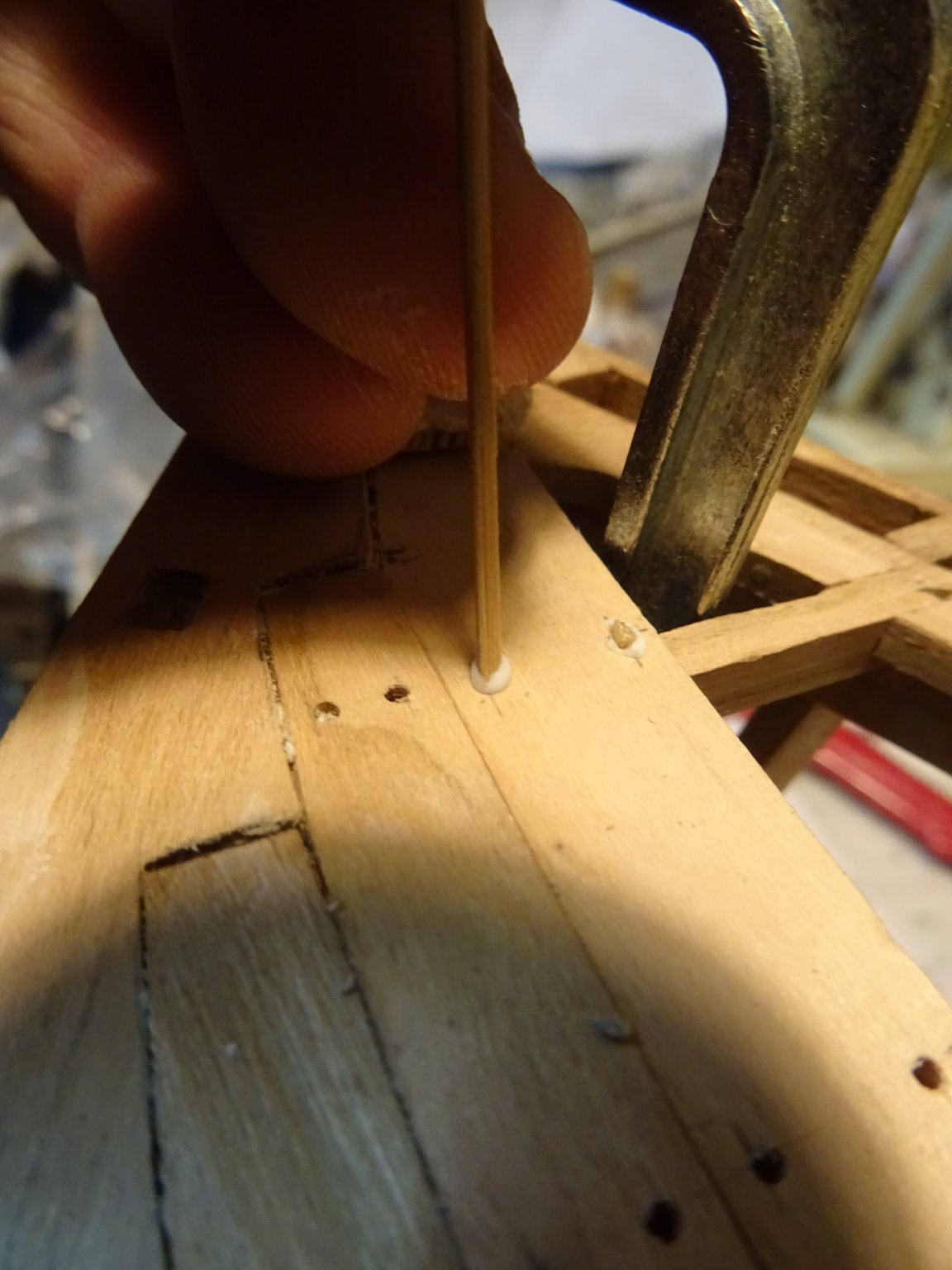
Now I start the tree nailing. Drilling the holes.
Before putting the nails, I erase all pencil markings from the deck. Erasing with the heads of the nails sticking out doesn't work so good and it is lethal for the eraser 😫.
I use bamboo tree nails (they are self made; plenty of bamboo in the garden). The tree nail is dipped in some wood glue ...

... pushed in the hole ...

... and pinched.
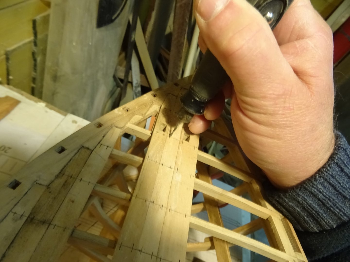
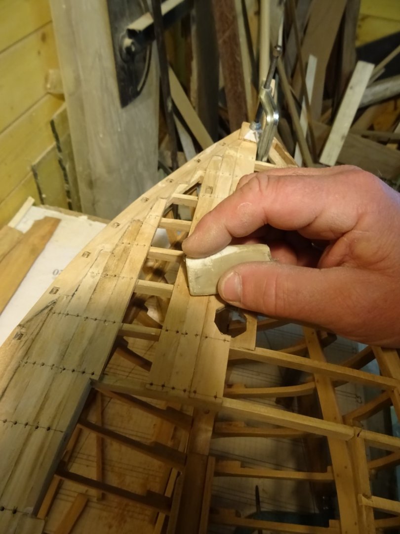
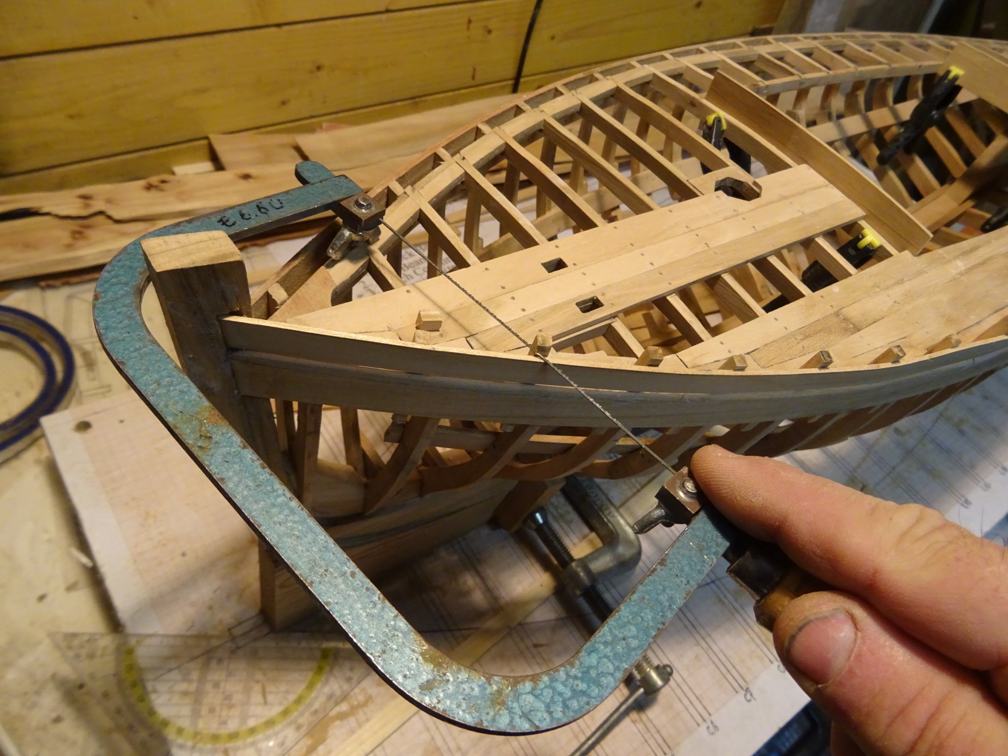
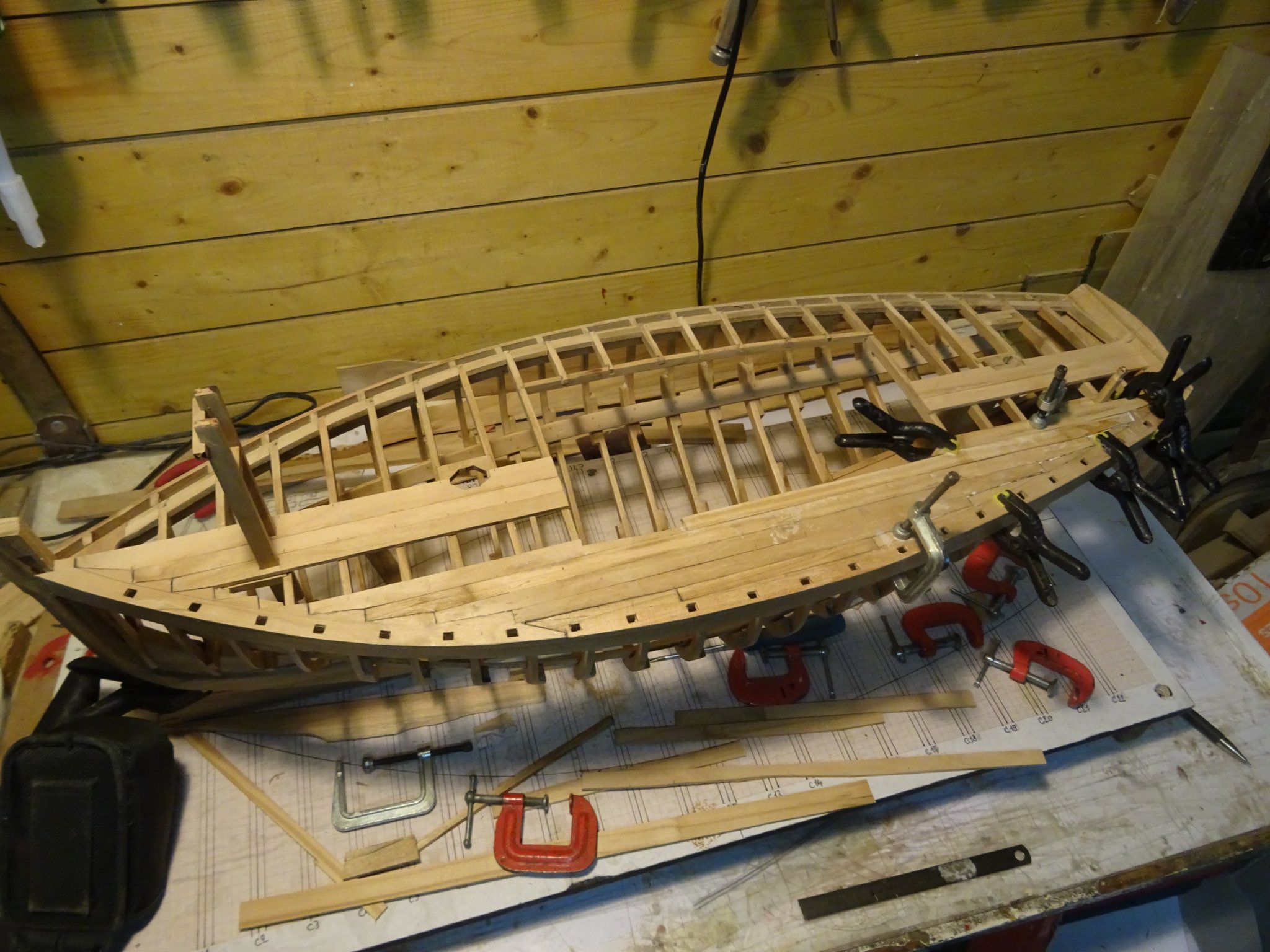
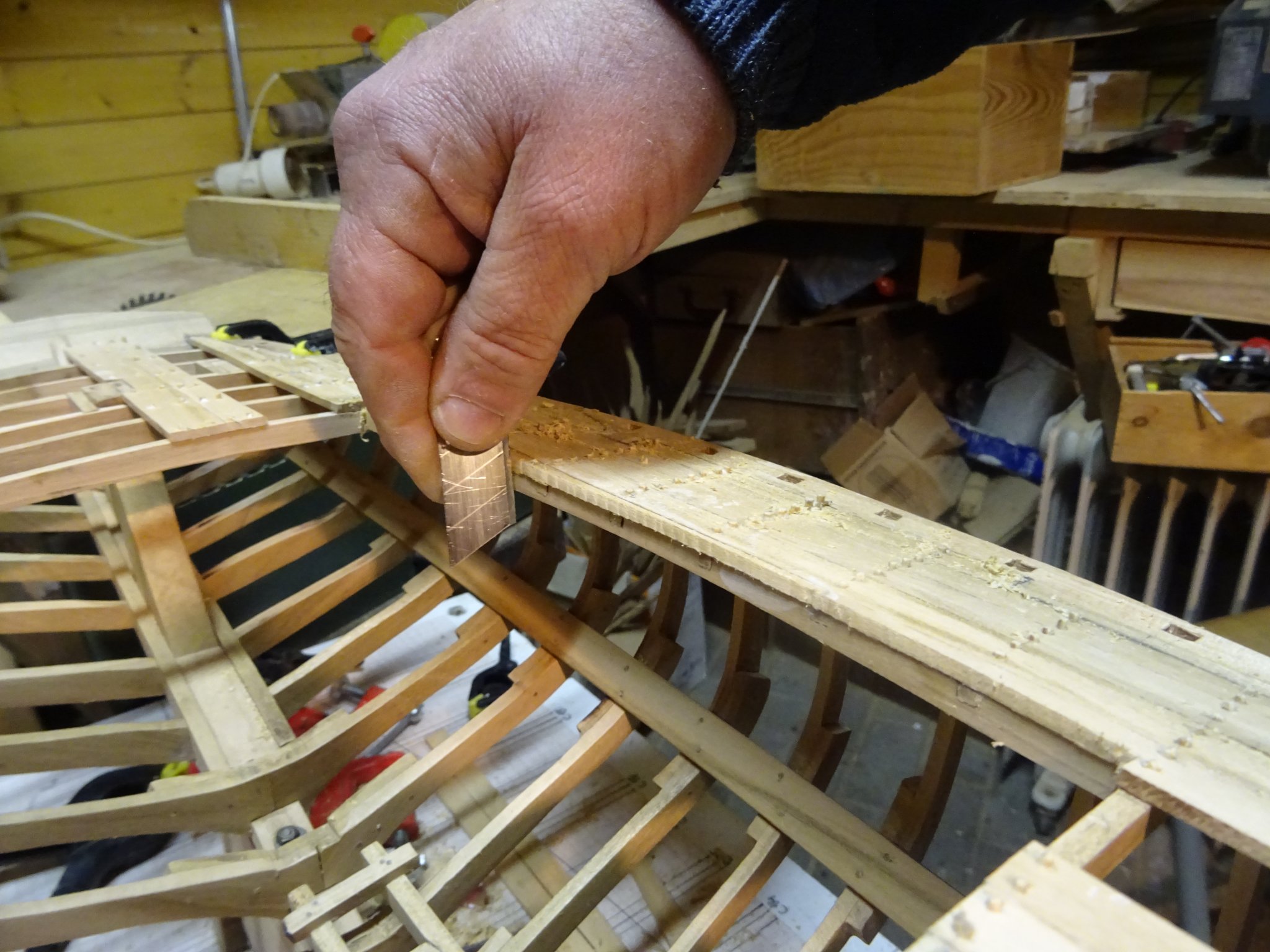
Now I saw out the edges of the cockpit...
...I scrape them also with a cutter knife blade...
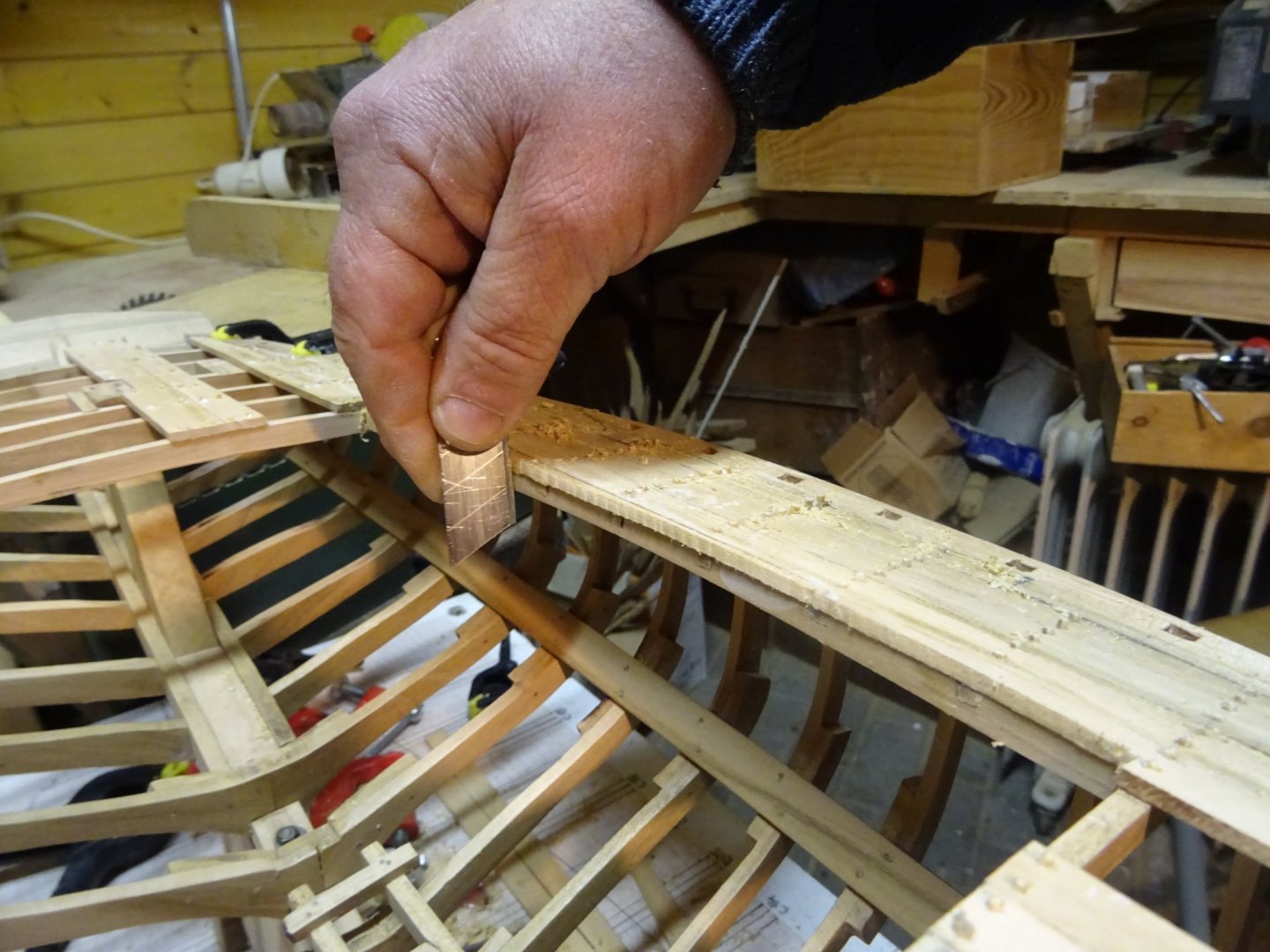
... and sand them.
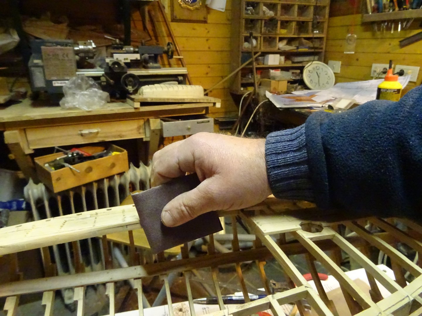

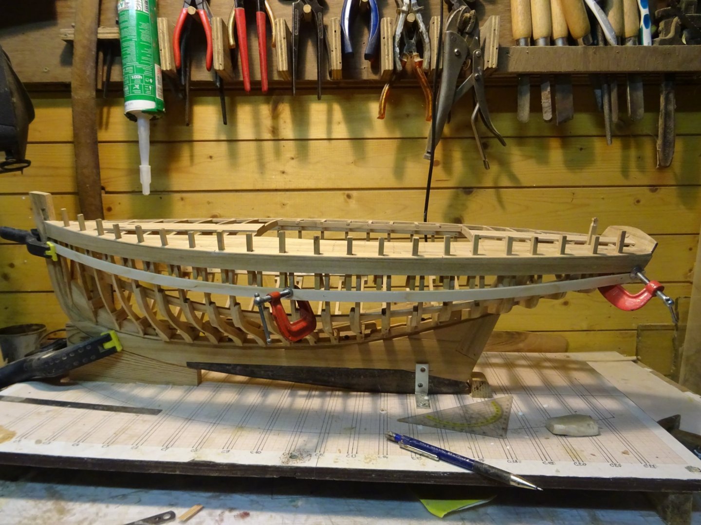
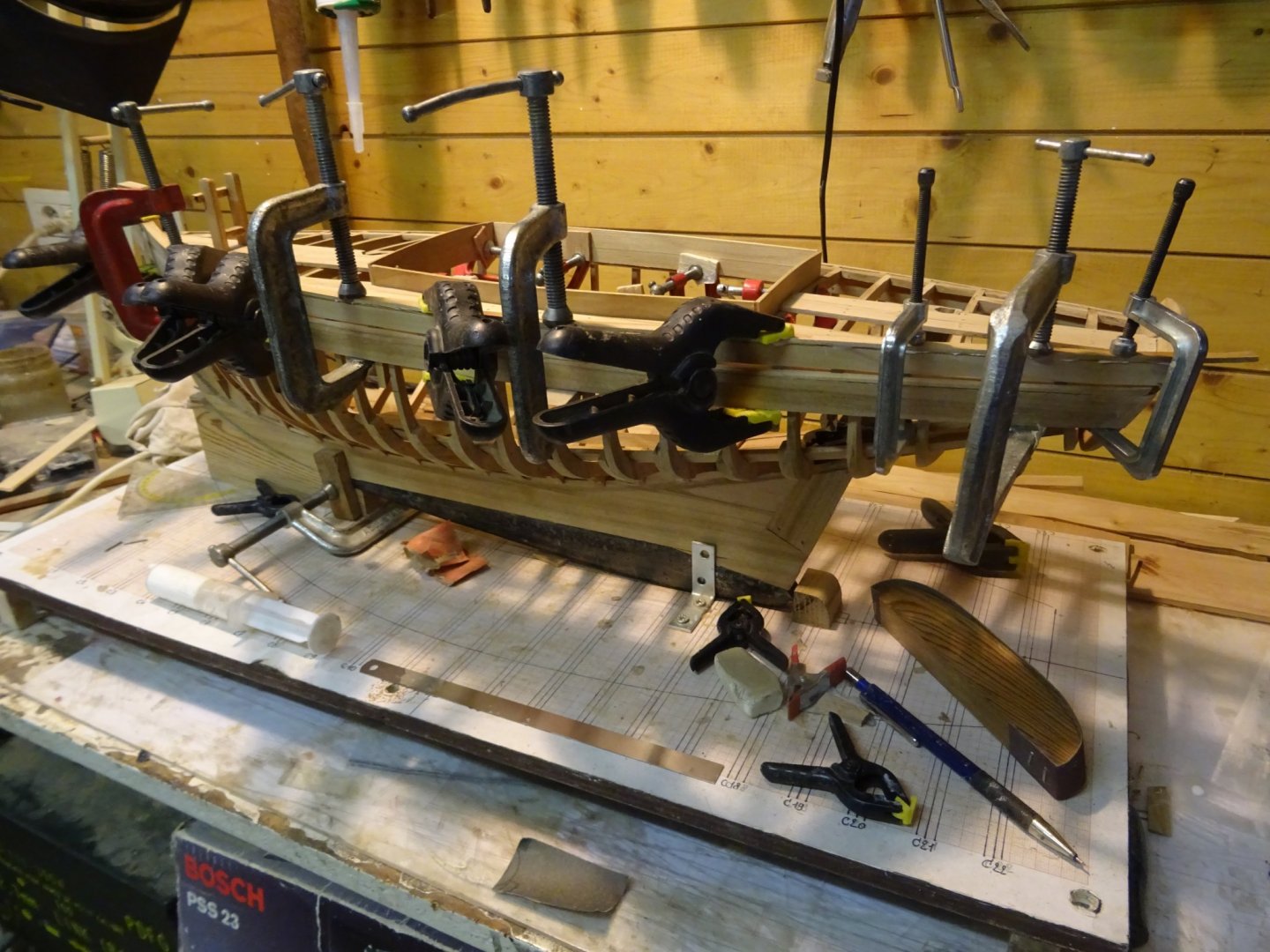
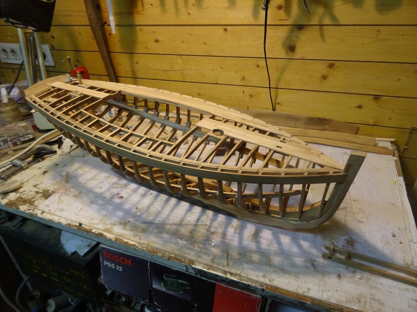
Next is scraping and sanding the deck. After it is done (the red clamp at the stern holds a little part of the waterway, which needed some more glue, in place):
Thank you to follow
Thank you for the likes
Till next week
-
On 2/22/2020 at 1:15 PM, mcpwilk said:
Beautiful work on both the hull, the rigging and sails. Surely the anchor rope should be attached with an anchor bend and whipping (https://www.netknots.com/rope_knots/anchor-bend) or a splice?
Mike
Mike, you are right. I used a spliced eye out of ignorance. Thank you very much to inform me about the anchor bend; yesterday I rectified my poor seamanship and gave my anchor an anchor bend.

-
On 2/22/2020 at 12:48 PM, Bedford said:
Love the oars Geert, I wouldn't have minded if you copied the leathering, that's what the site is about. Learning from each other, getting ideas from each other etc.
Having said that, I do like the darkened rope on your oars.
On 2/24/2020 at 12:19 AM, BobG said:I have just begun to look over your build log. Lovely boat and superb craftsmanship!
Bob
Steve and Bob,
Thanks for your kind remarks.
-
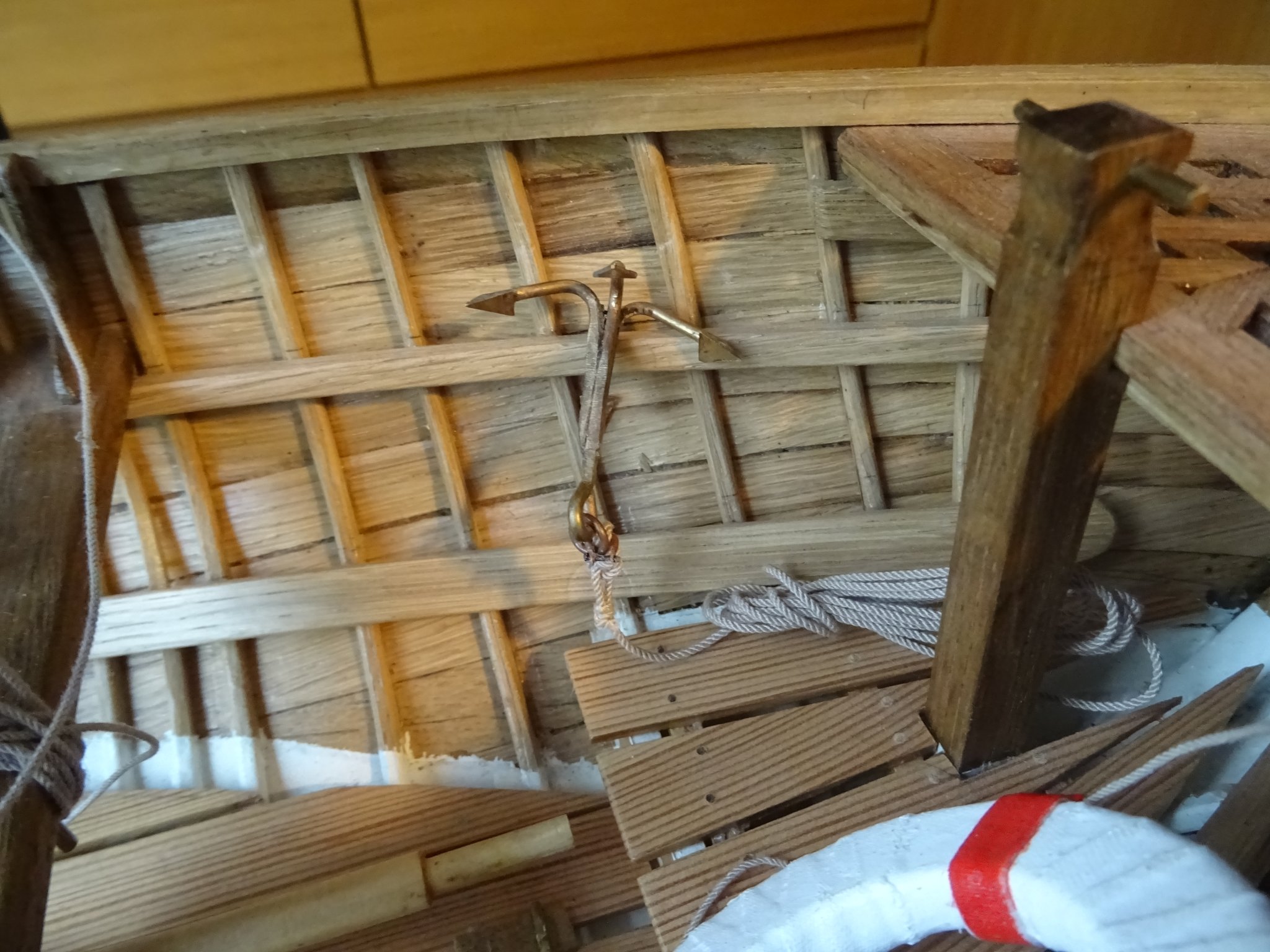
14.2 The anchor
The inventory contains also a small brass anchor.

Thank you for the likes
Thank you to follow
Thank you for the constructive comments.
Till next week!
- GrandpaPhil, ccoyle, Baker and 11 others
-
14
-
For the moment I am continuing the sewing of the sails. Reporting each week how many cm of the leach is sewed or how many thimbles are sewed in the sail during the last week would be boring, because it has been showed already when making the jib. Therefore while continuing to finish the main sail, I will make some posts of the making of some pieces of the boat inventory which are already made during the last months and didn't found a place in this log yet.
14. The boat inventory
14.1 The oars.
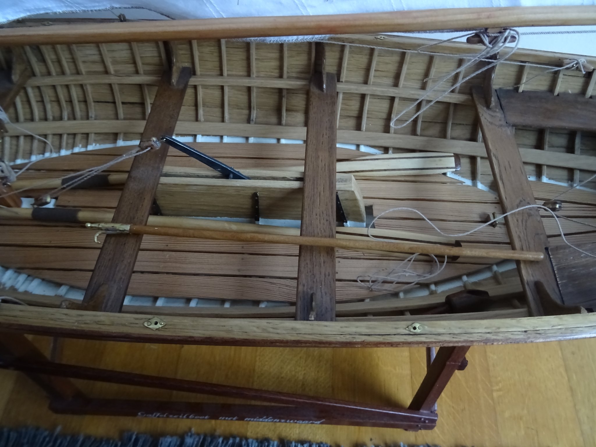
This boat can not only be used as a sail boat but also as a double row rowing boat with 6 oarsmen and a coxwain. Normally it should have 6 oars. I present the vessel as a sailing boat. Laying 6 oars in the boat would be obstructive for the sailing crew so I will limit to two oars.
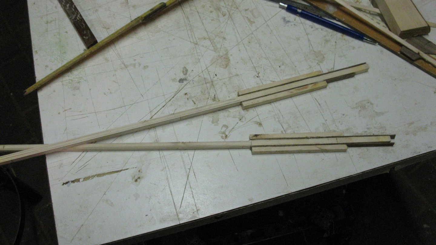
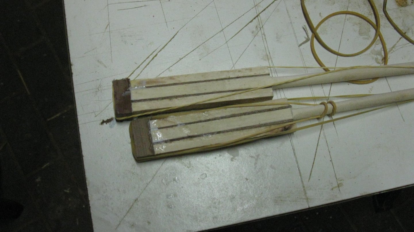
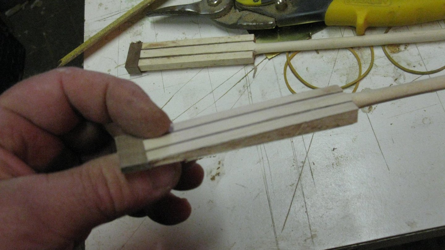
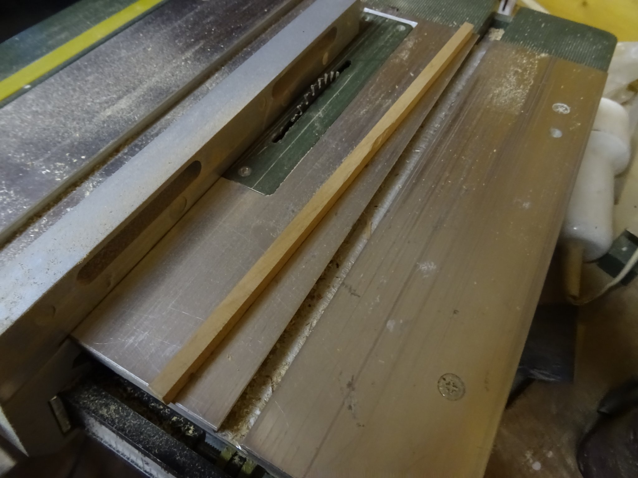
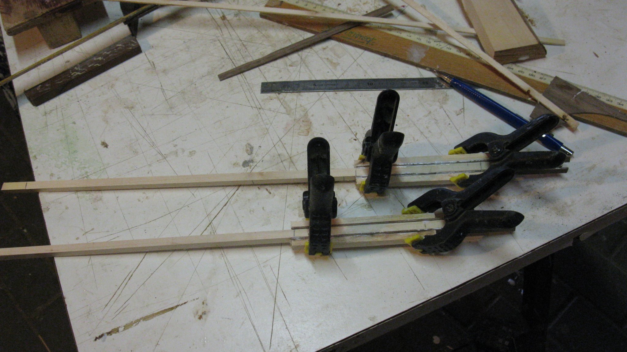
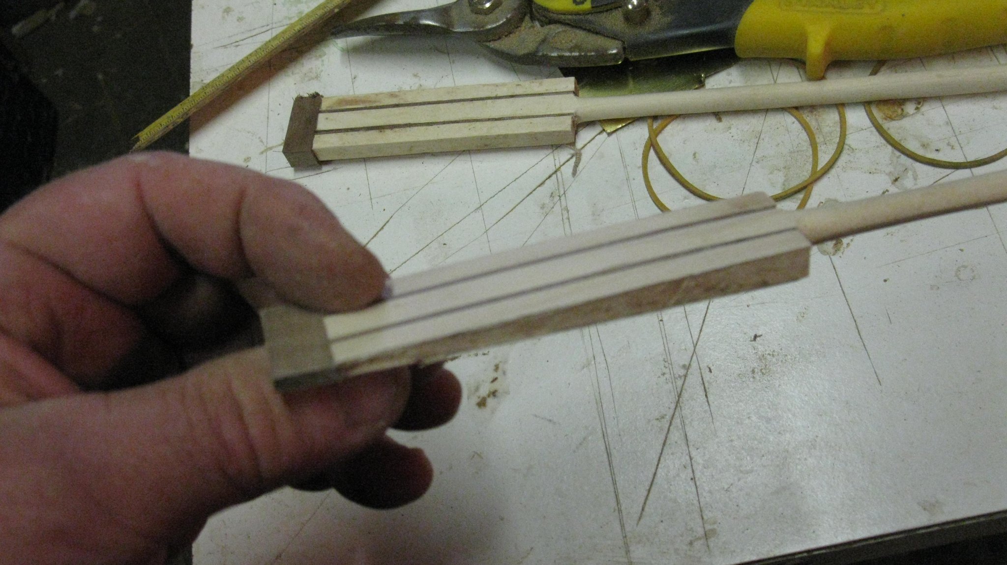
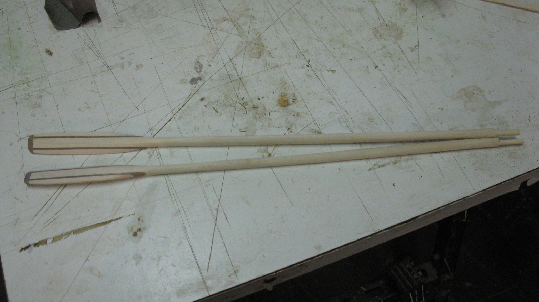
To make the oars, I start with gluing the rough shapes of them, using two sticks of maple wood which will become the shafts. The blades are made of gluing two strips of walnut at each side of the shaft and another two pieces of maple at the outside.
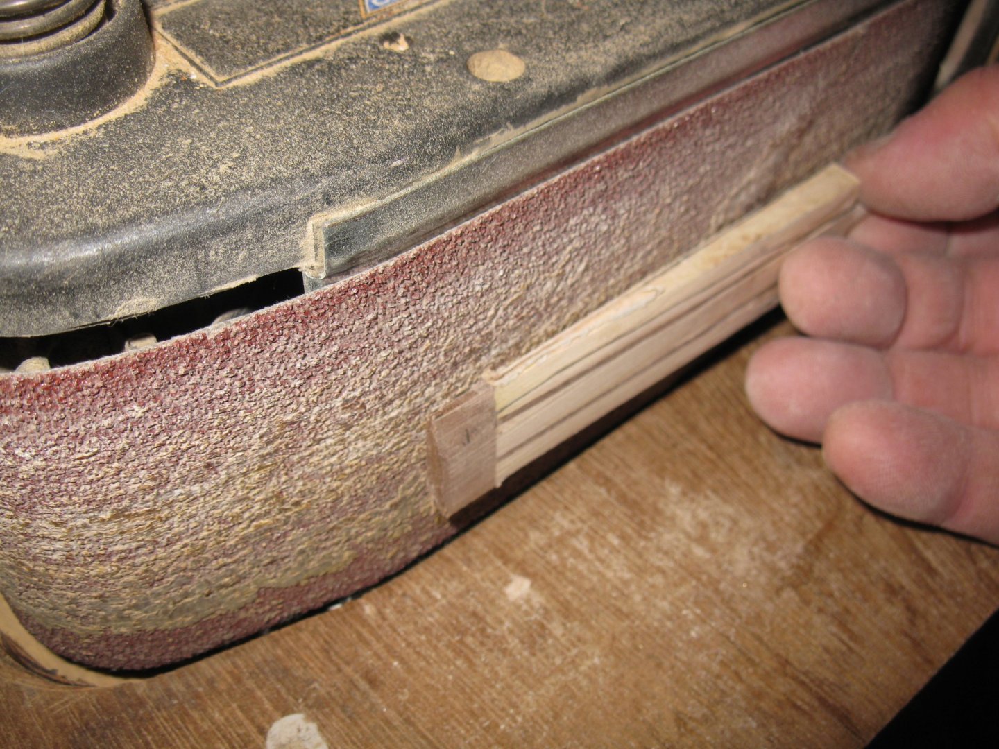
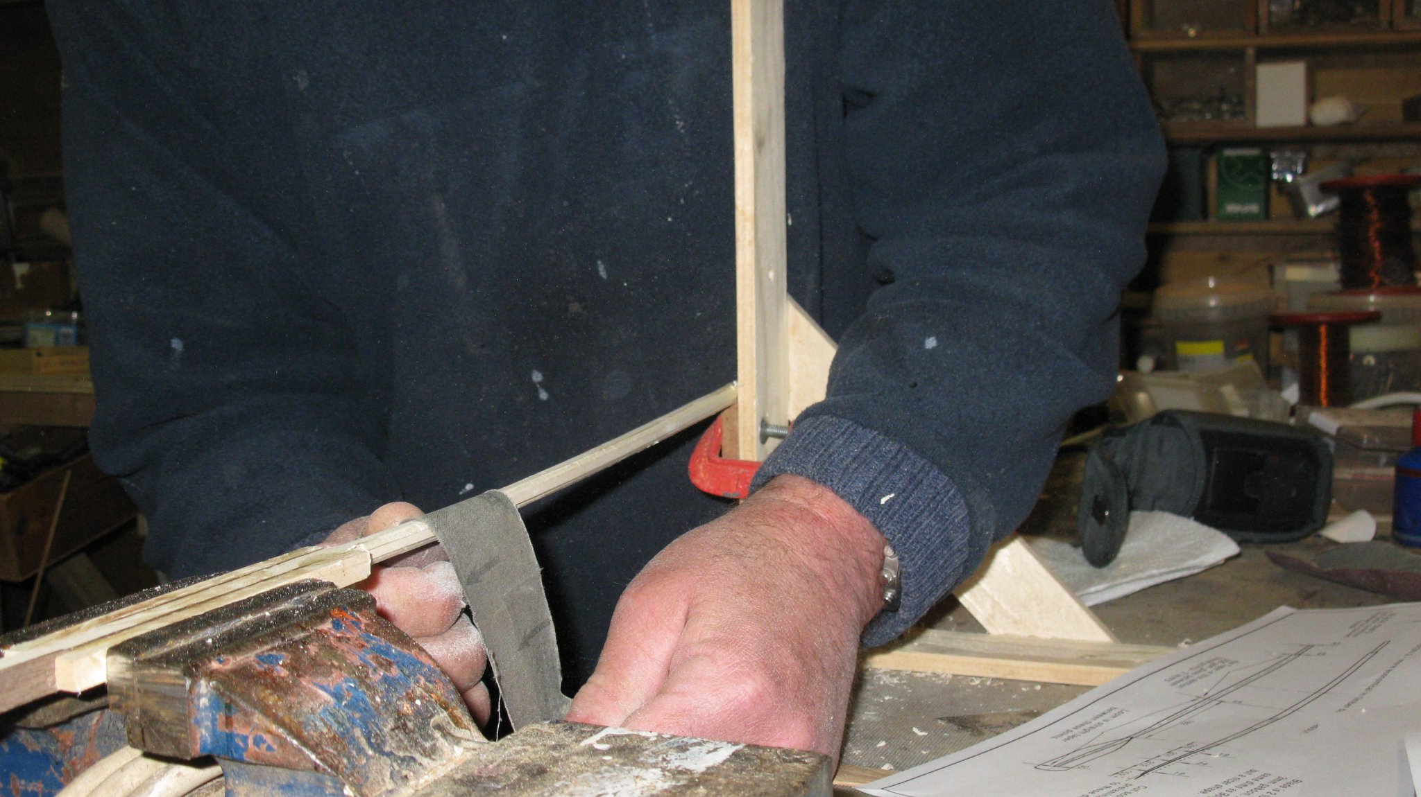
Shaping the shafts: first I scrape them to an octagonal shape, afterwards I sand them round, just like I would make a spar.

Before shaping the blades, I saw them straight at the end and glue a piece of walnut in place.
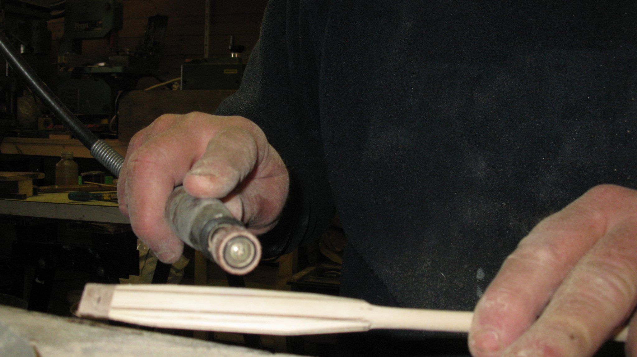
The shaping of the blades is mainly done by sanding them.

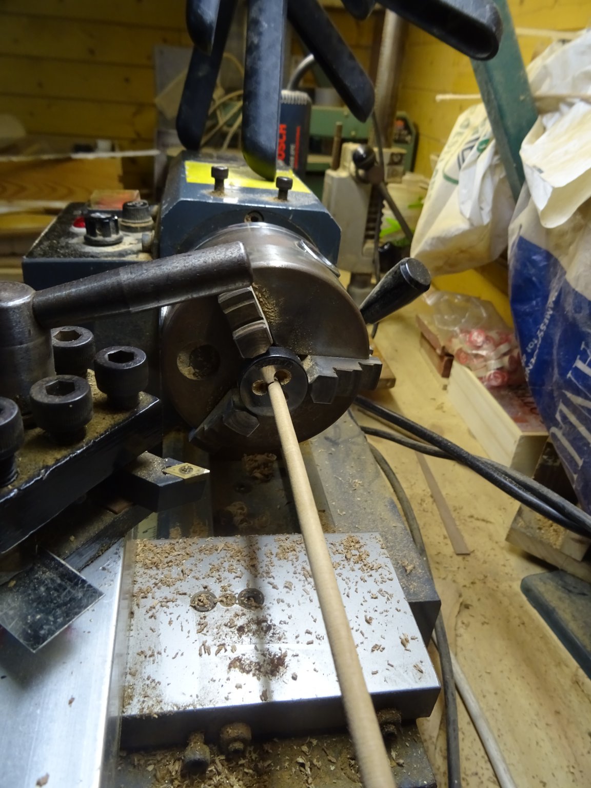
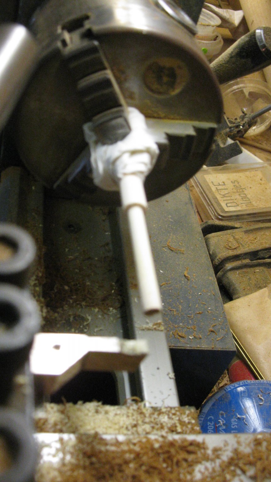
The handles are turned out on the lathe.

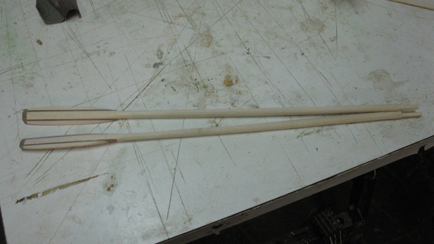
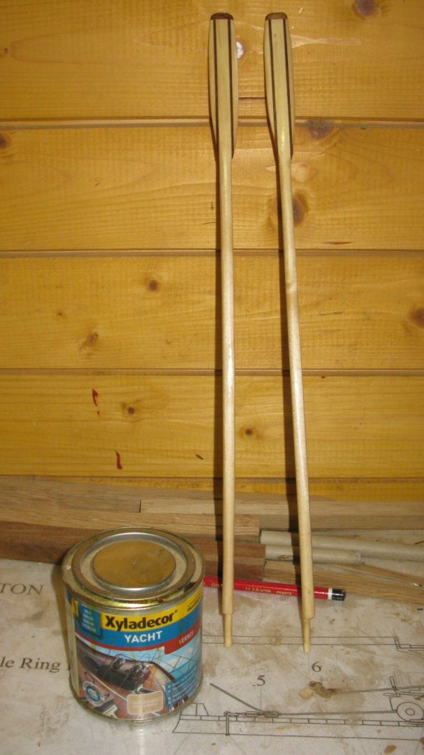
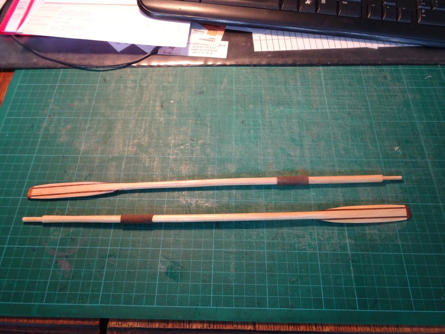
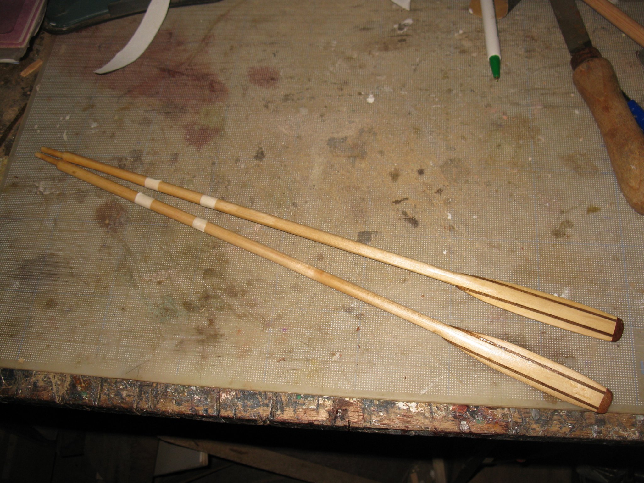
The two oars are shaped and can be varnished.
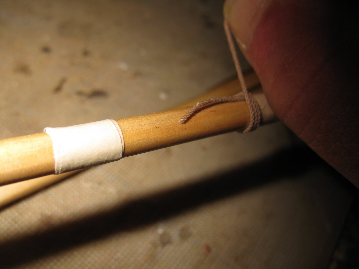
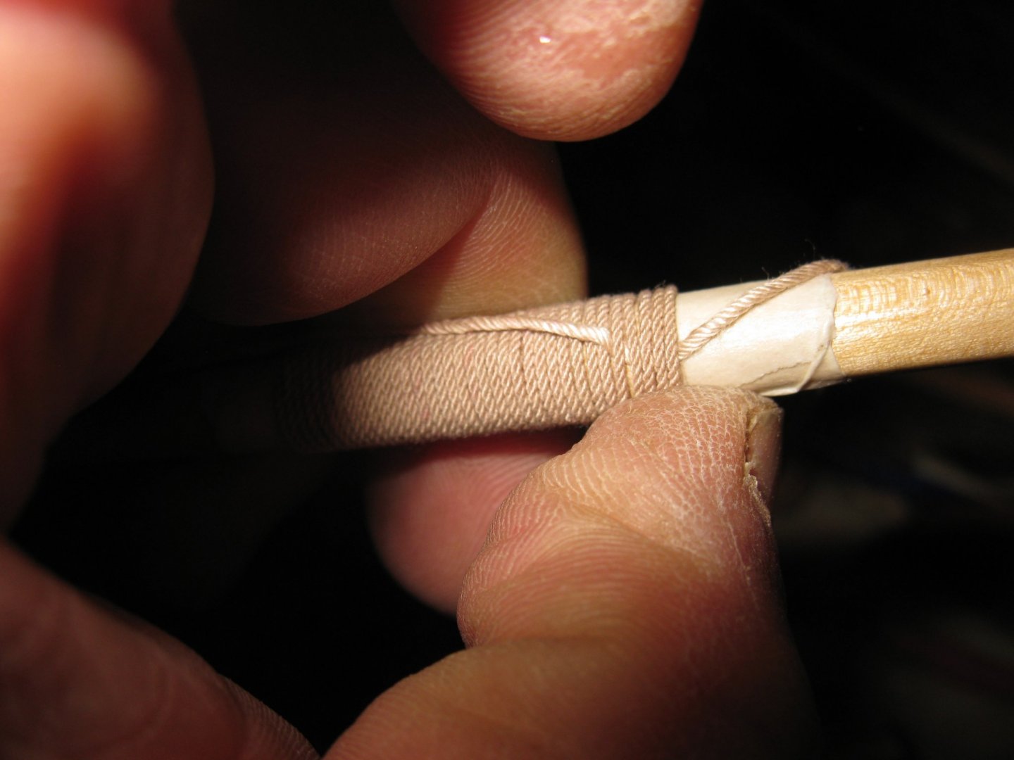
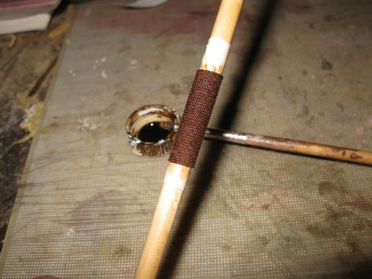
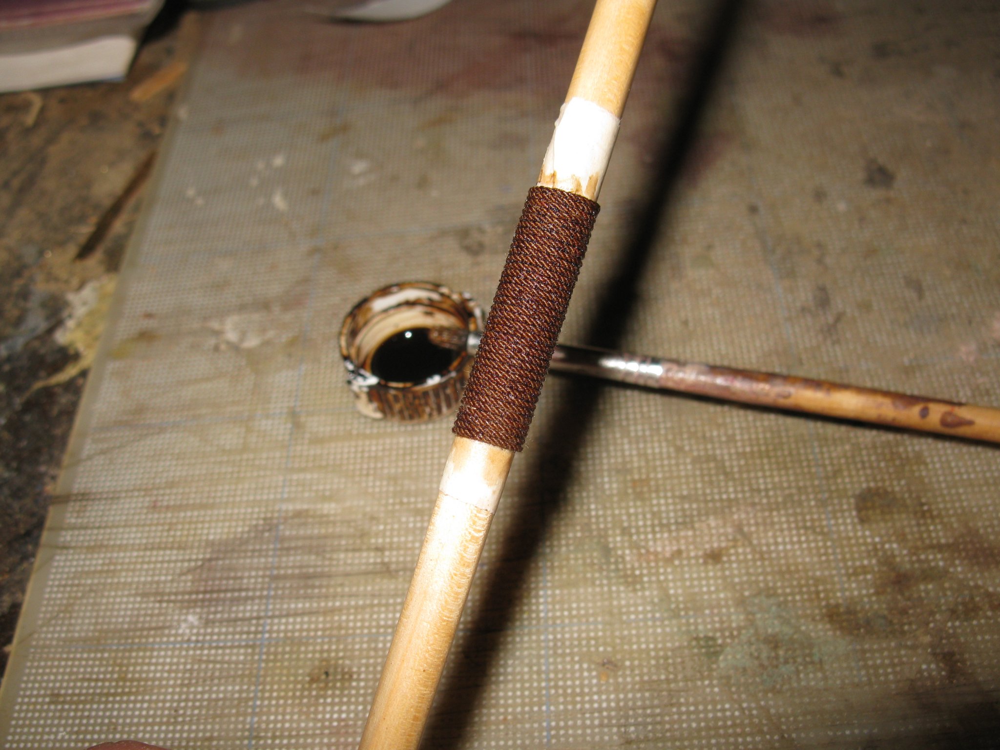
My oars need a collar to prevent them from wear and tear by the oarlocks. Unfortunately I made my oars before Steve (Bedford) made the oars for his 'Miss Caroline'. I made a collar with a tackle of rope. A leather collar like Steve's would be better. I will not change it any more, that would be too plagiatic.
Making the tackles:

To finish them, I stain them dark.
The oars:
-
-
18 minutes ago, Backer said:
An old photo frame that my wife wanted to throw away. The inside is filled with a wooden plate
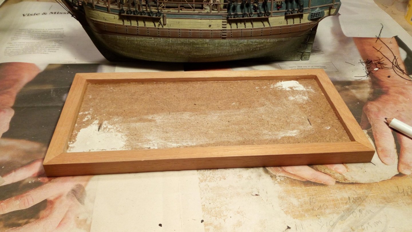
An old picture frame. Very good idea.
- Barbossa, popeye the sailor and Baker
-
3
-
Indeed a very charming model, Javier. How do you write the name and the number on such a small scale?
- Mirabell61 and mtaylor
-
2
-
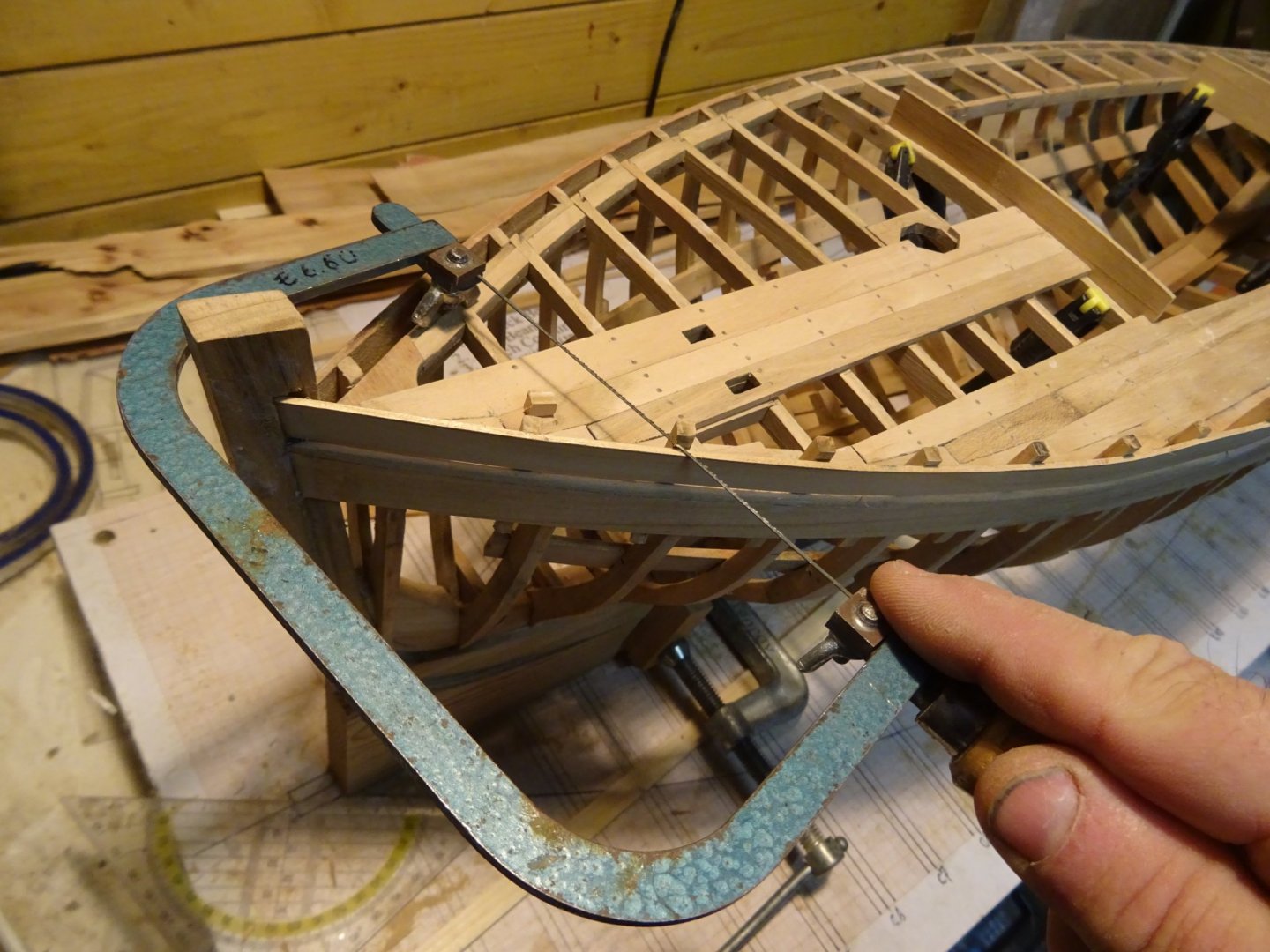
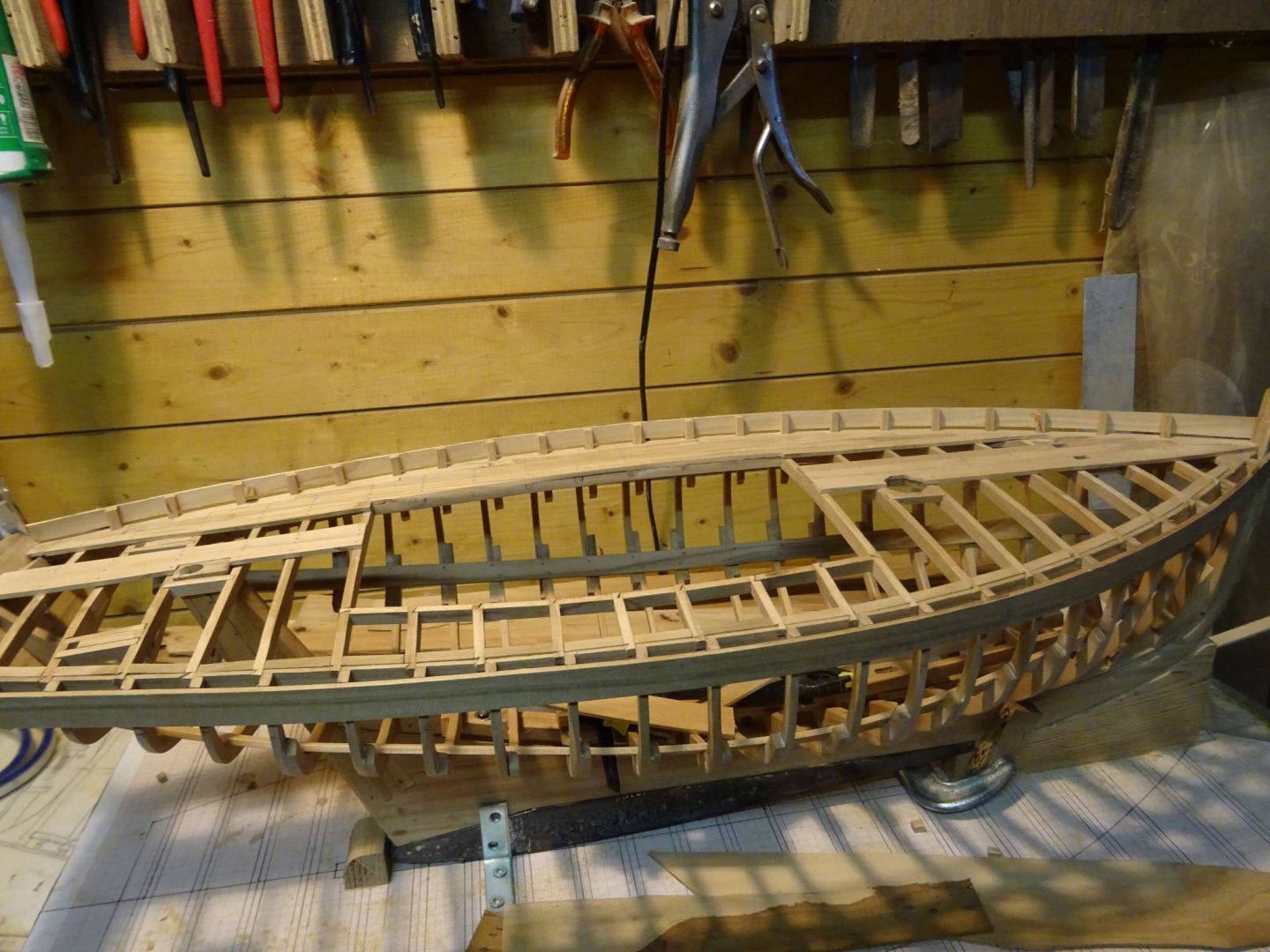
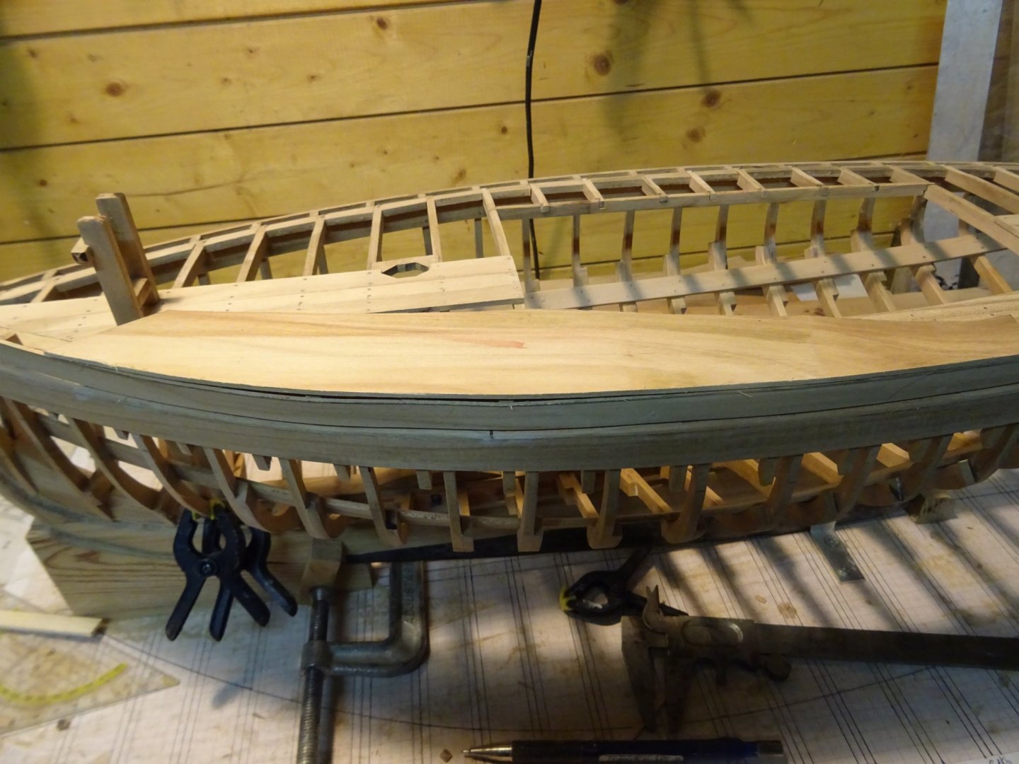
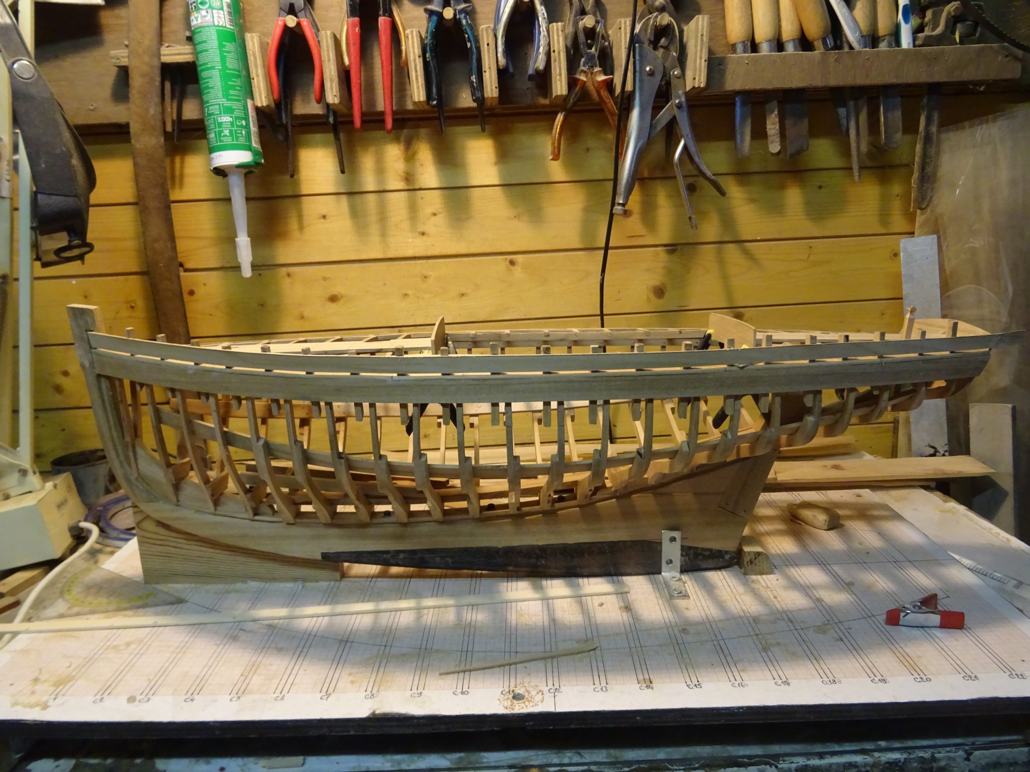
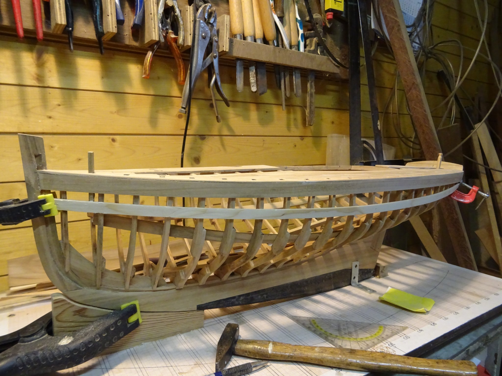
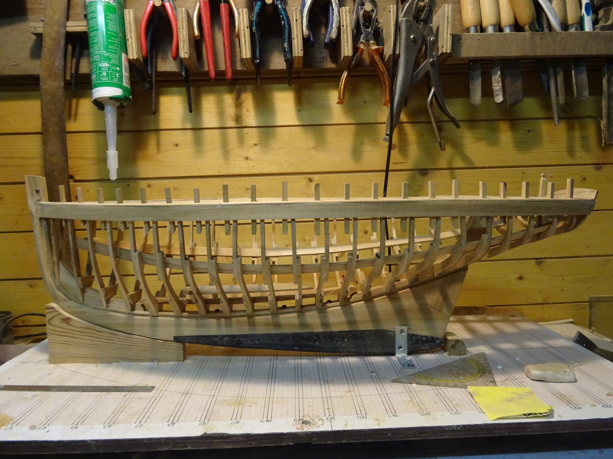
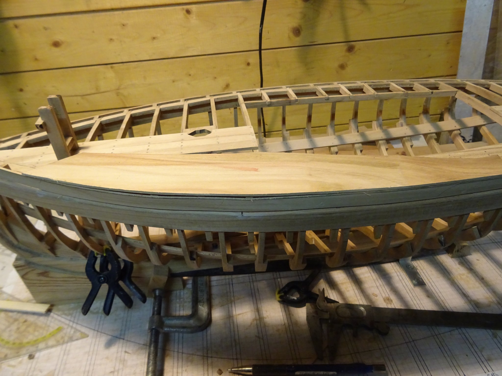
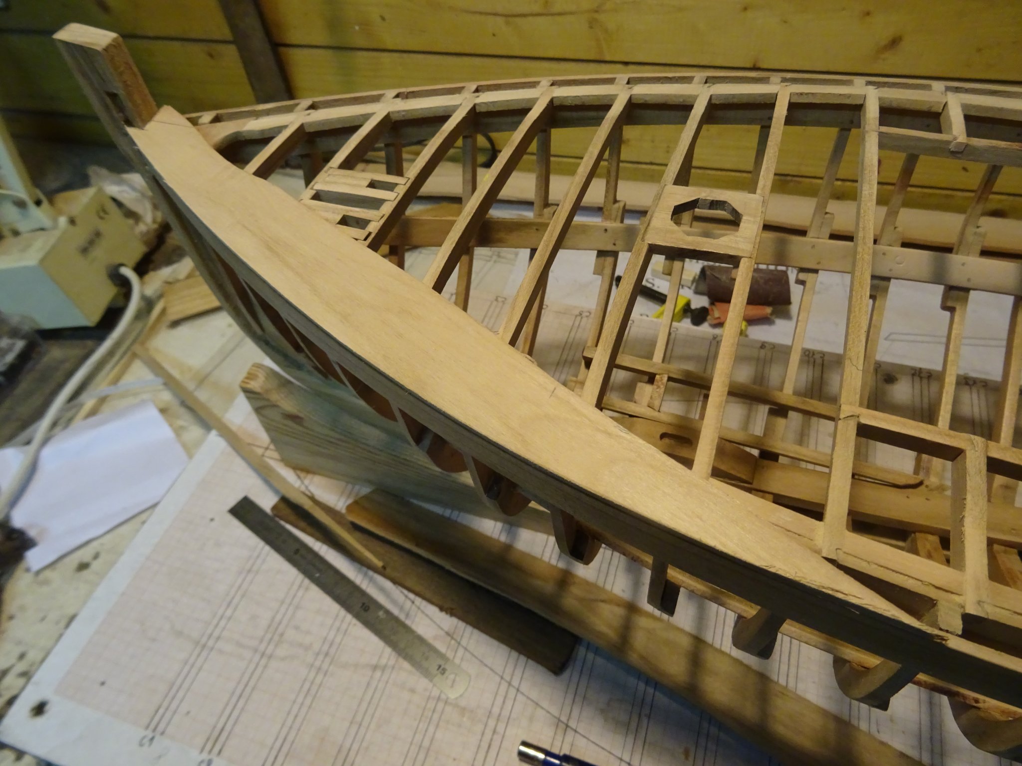
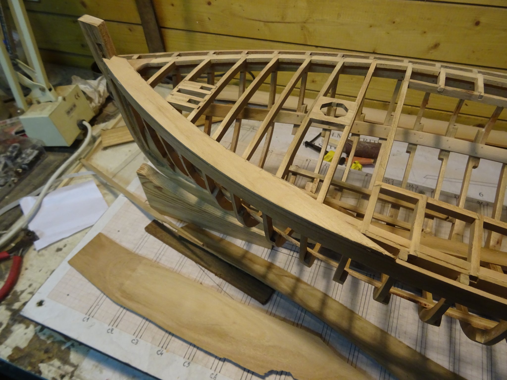
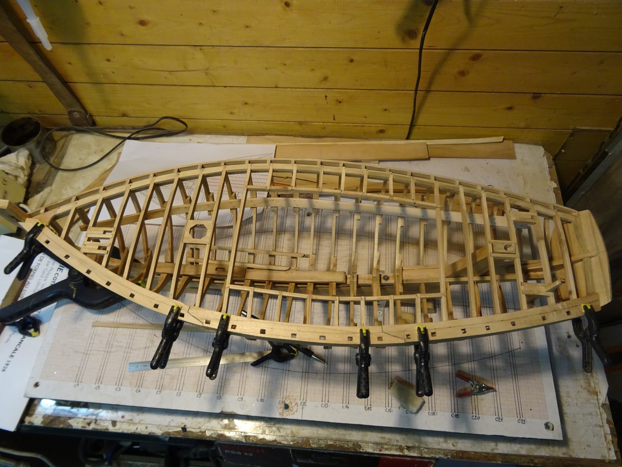
6. The deck
Small reminder: this is an instruction model to teach the different parts of a small wooden sailing vessel. Keeping that in mind, the deck will only be laid partially at the port side. The starboard side will be left open, even without a railing.
Here I will also deviate a little bit from the ship drawing. I am not building the mackerel cutter 'Marie', but I am using the plans of 'Marie' to build a generic instruction model. I think that I can afford this freedom.
The drawing below shows my intention.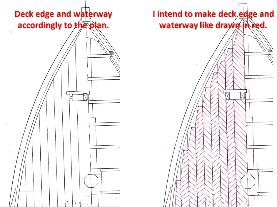
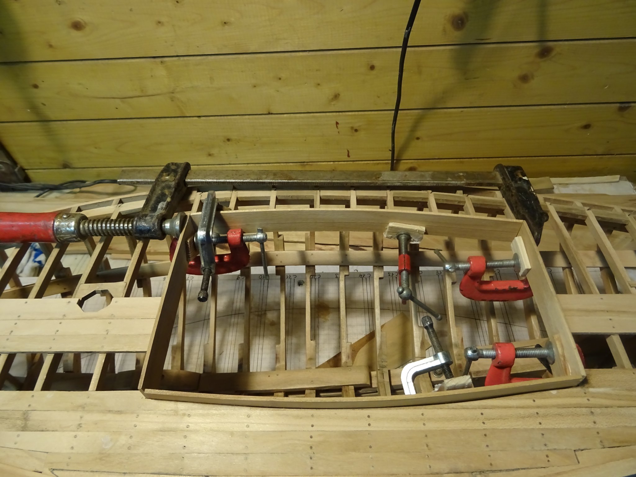
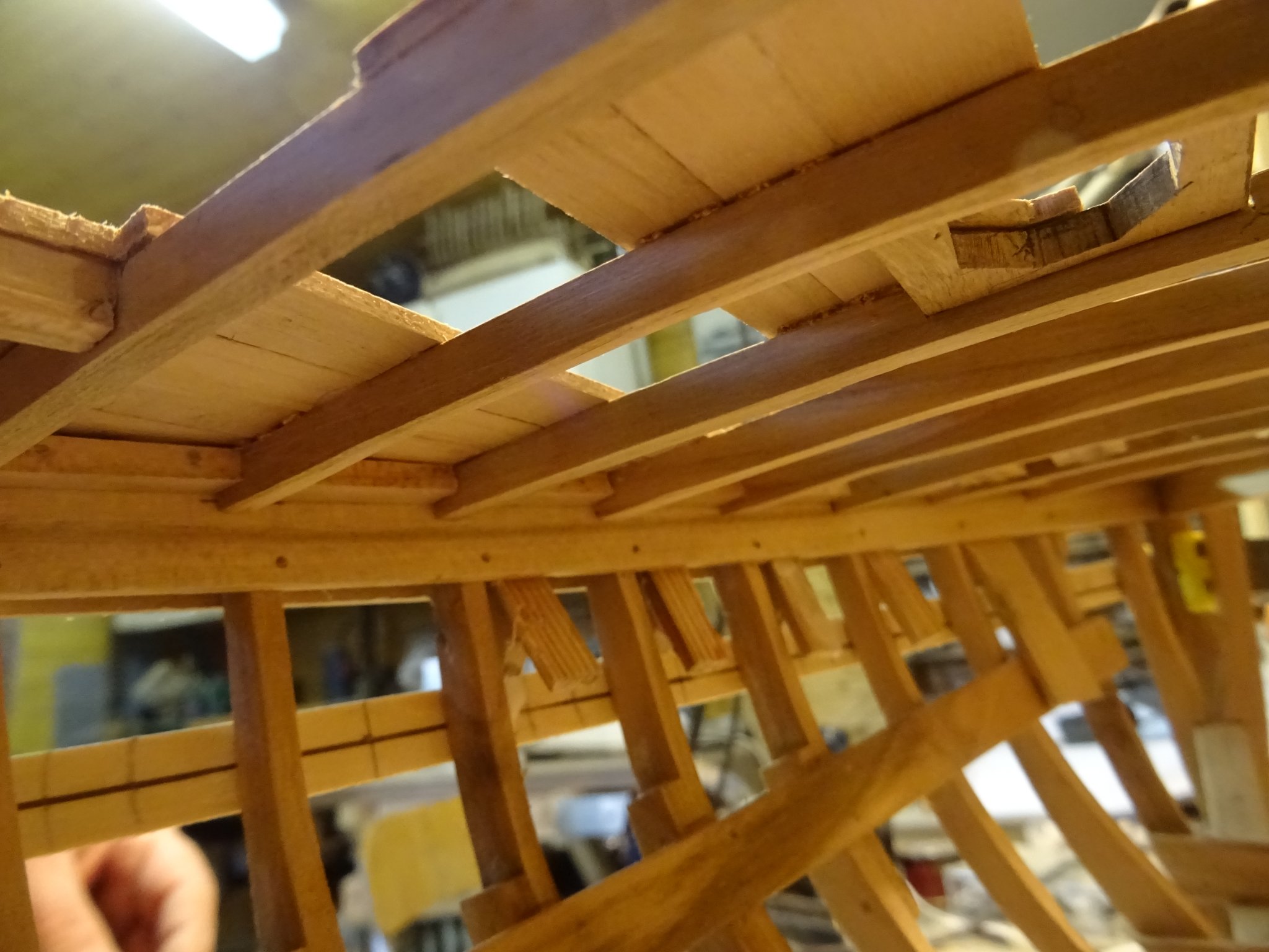
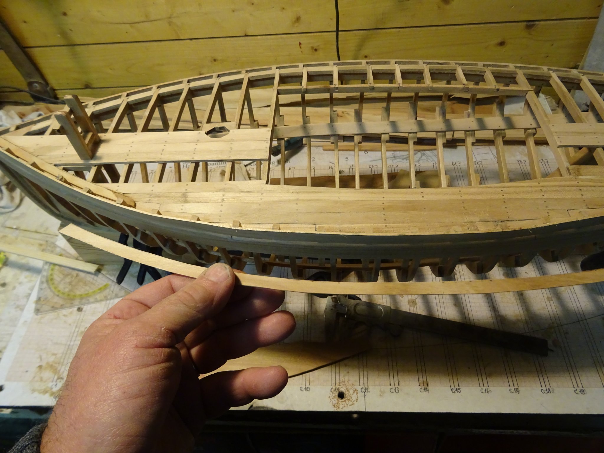
I first make the waterway. Marking the shape of the wale on the bottom side of the plank.
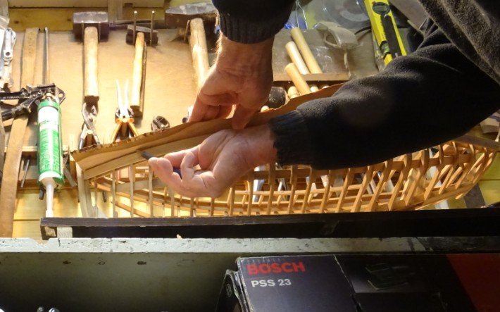
The outer edge of the plank is sawn, fitting it.

With the inner edge sawn. I make the plank wide enough to make the nicks for the deck planks.

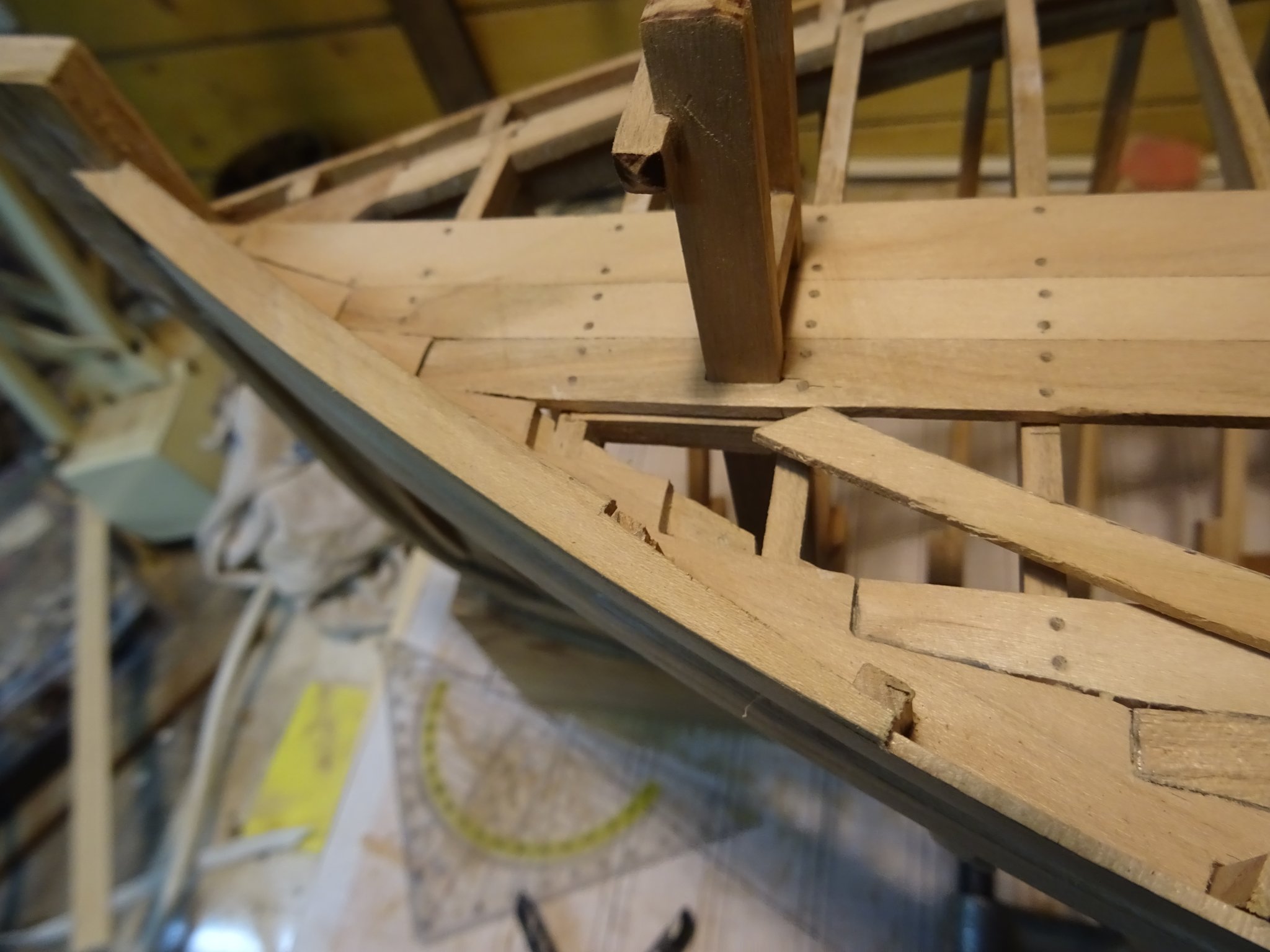
The waterway will be made in three pieces. Here you see the two outer pieces. I make them long enough to have a large overlap to make the joints between the different pieces.
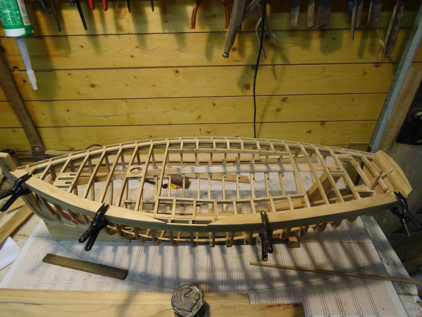
The three pieces on top of each other.
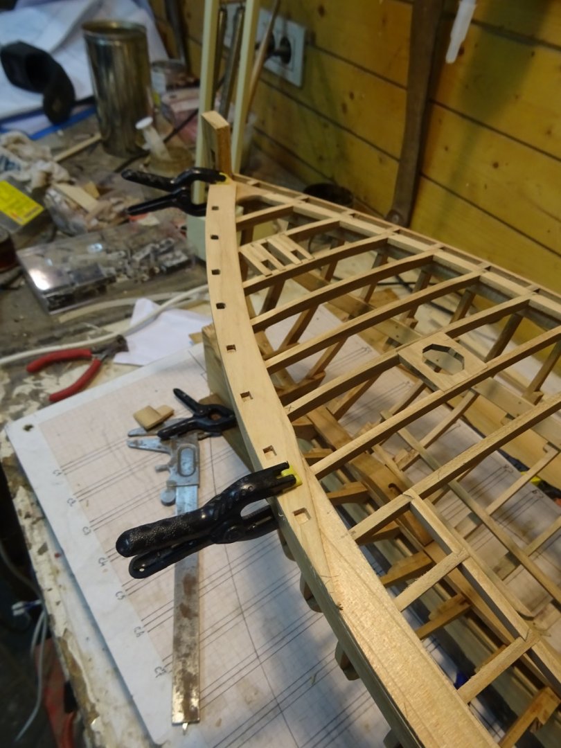
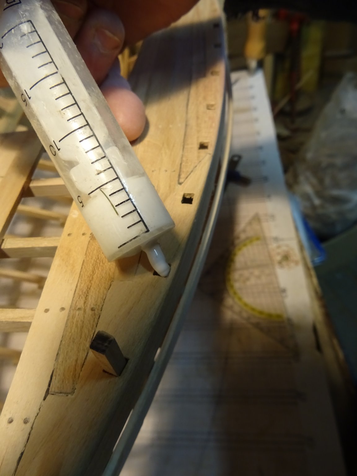
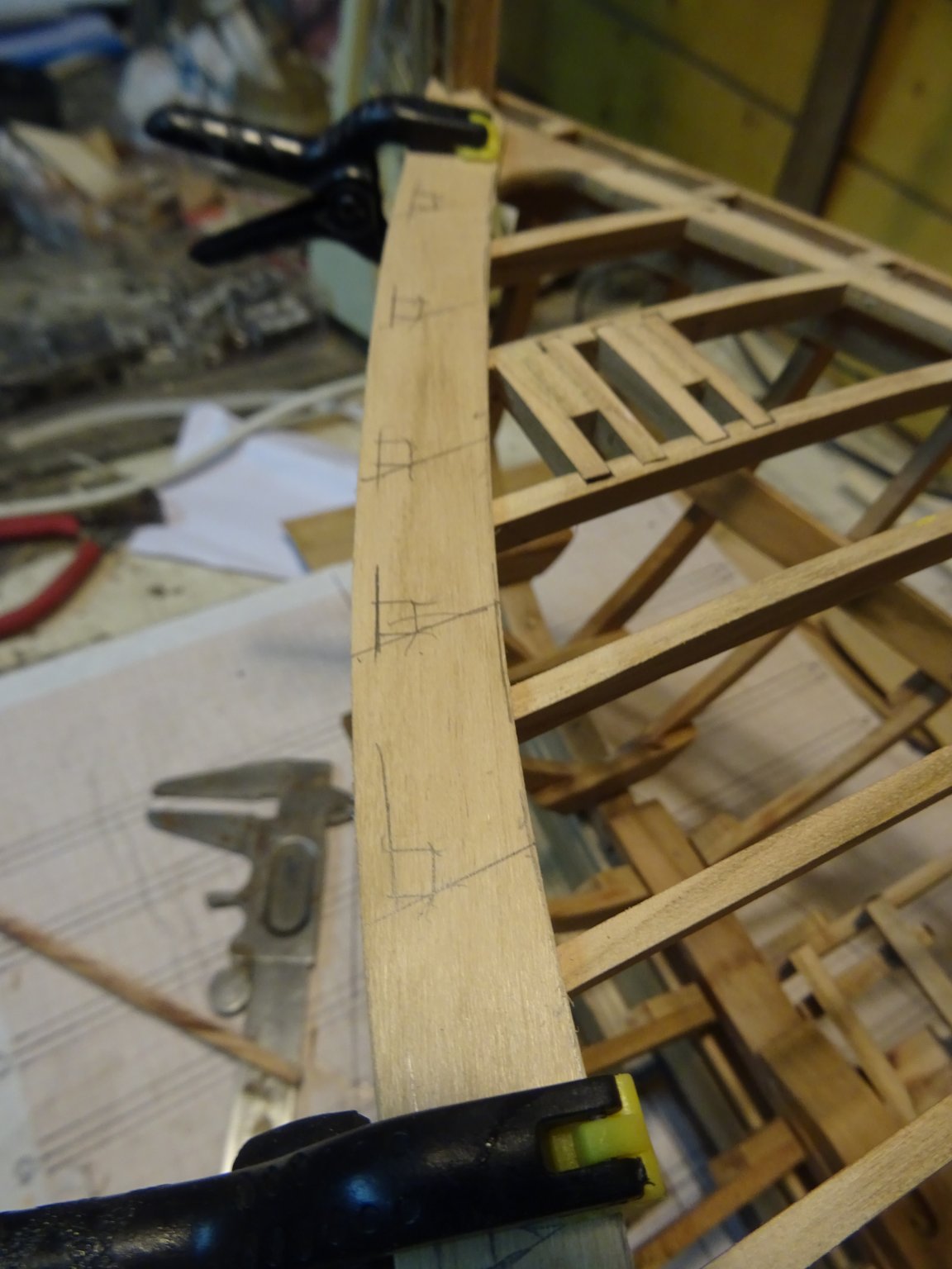
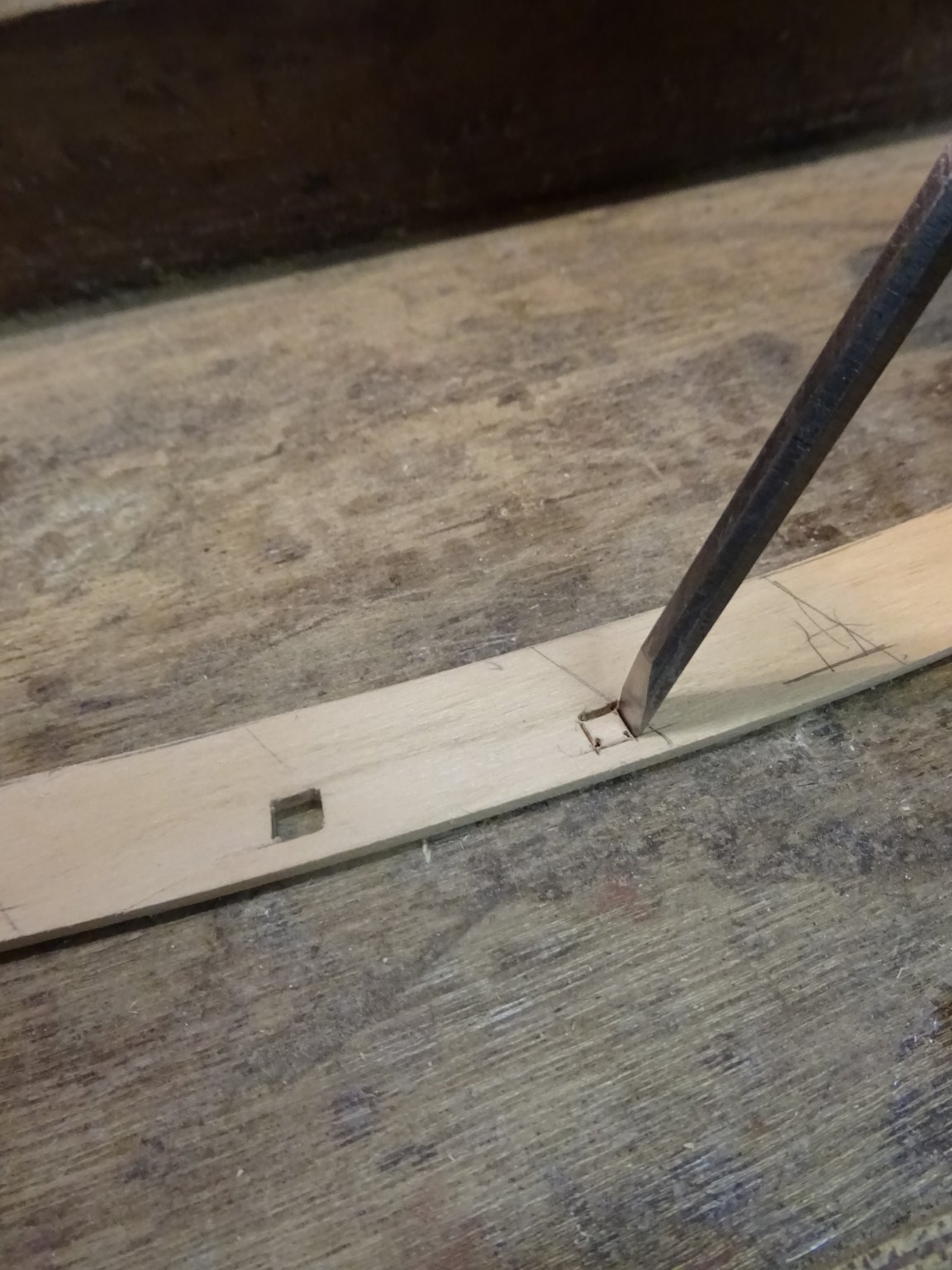
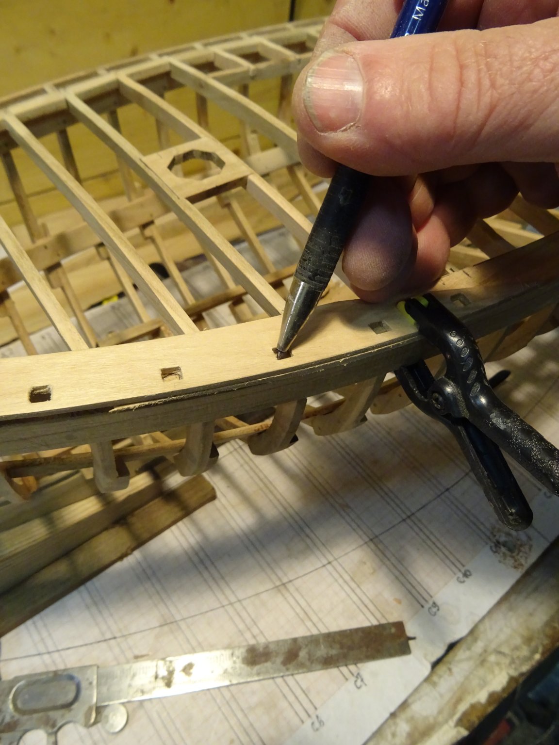
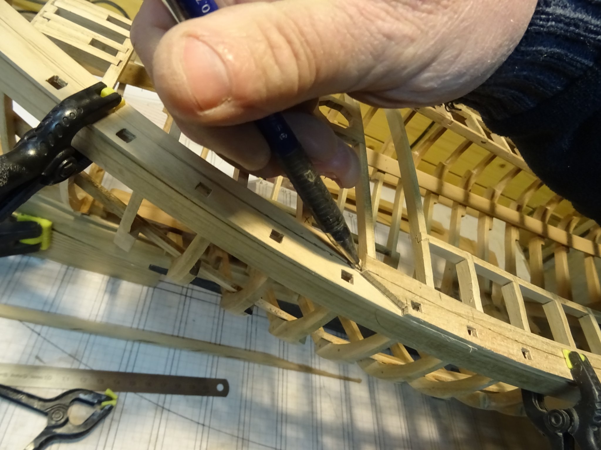
Marking the spots where apertures have to be made for the top timbers which support the bulwark. Those top timbers are not a part of the frames. They are short squared bars which are going through the waterway.
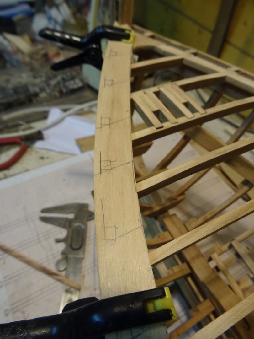
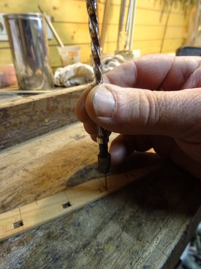
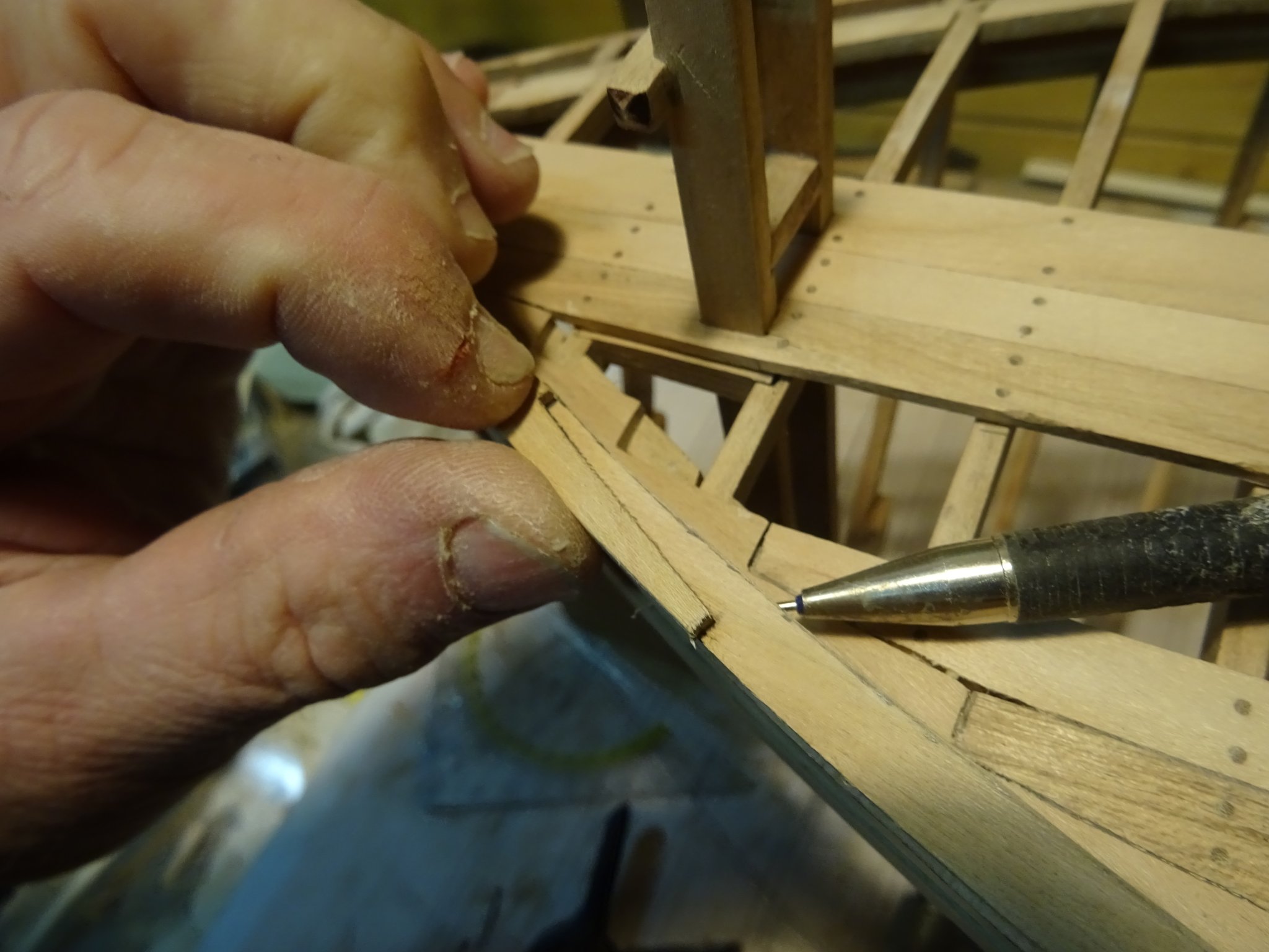
To make the apertures. I drill first a 1mm hole in the corners and then cut out the opening with a wood chisel. The hole that I drilled prevents the wood to split when giving some pressure on the chisel. In any case the cutting has to be done with some care.
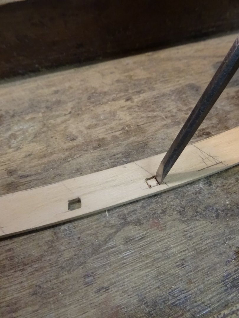
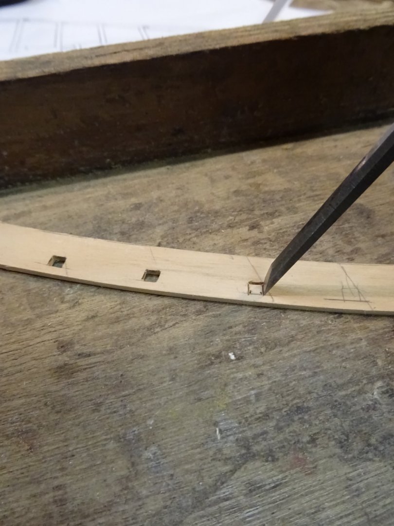
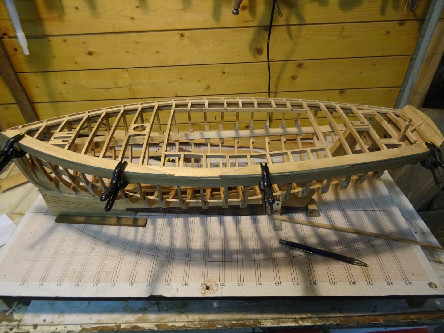
The forward piece:
Marking the second piece. The holes must correspond where there is an overlap. The decision where to cut the joints between the pieces can still wait a bit.

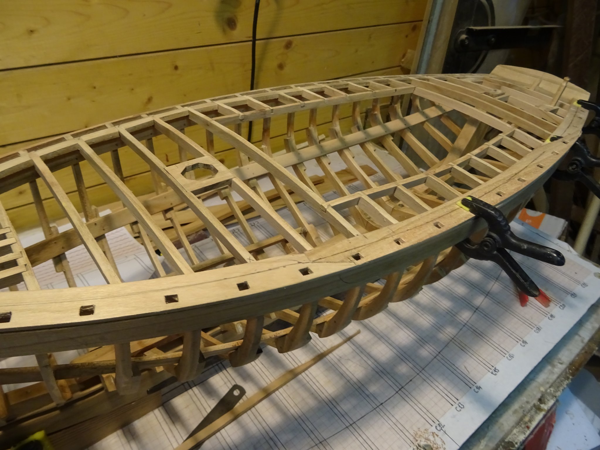
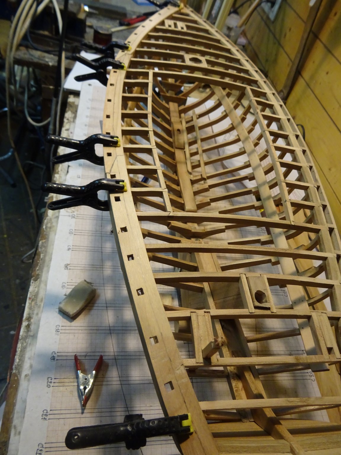
The three parts of the waterway are ready.
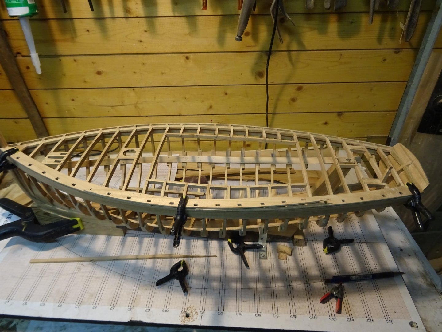
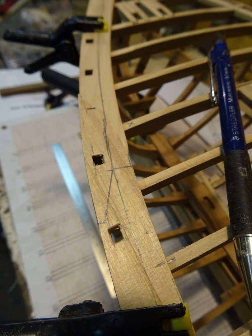
I am now looking where I will make the joints between the different parts of the waterway. Here I marked the forward joint of the middle part of the waterway. On the waterways you see also a pencil line, parallel to the inner edge. This breath is the space in where the nicks of the deck planks have to fit.
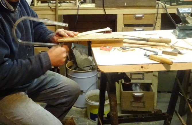
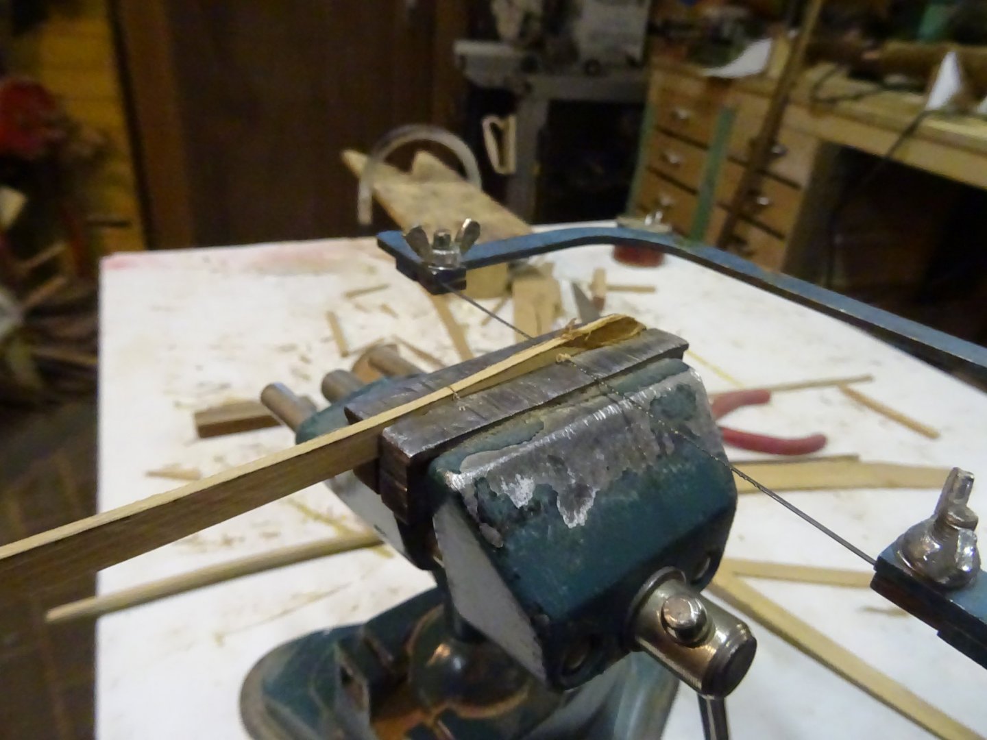
Sawing out the joint. I use the vise to saw pure in straight line along the marking.
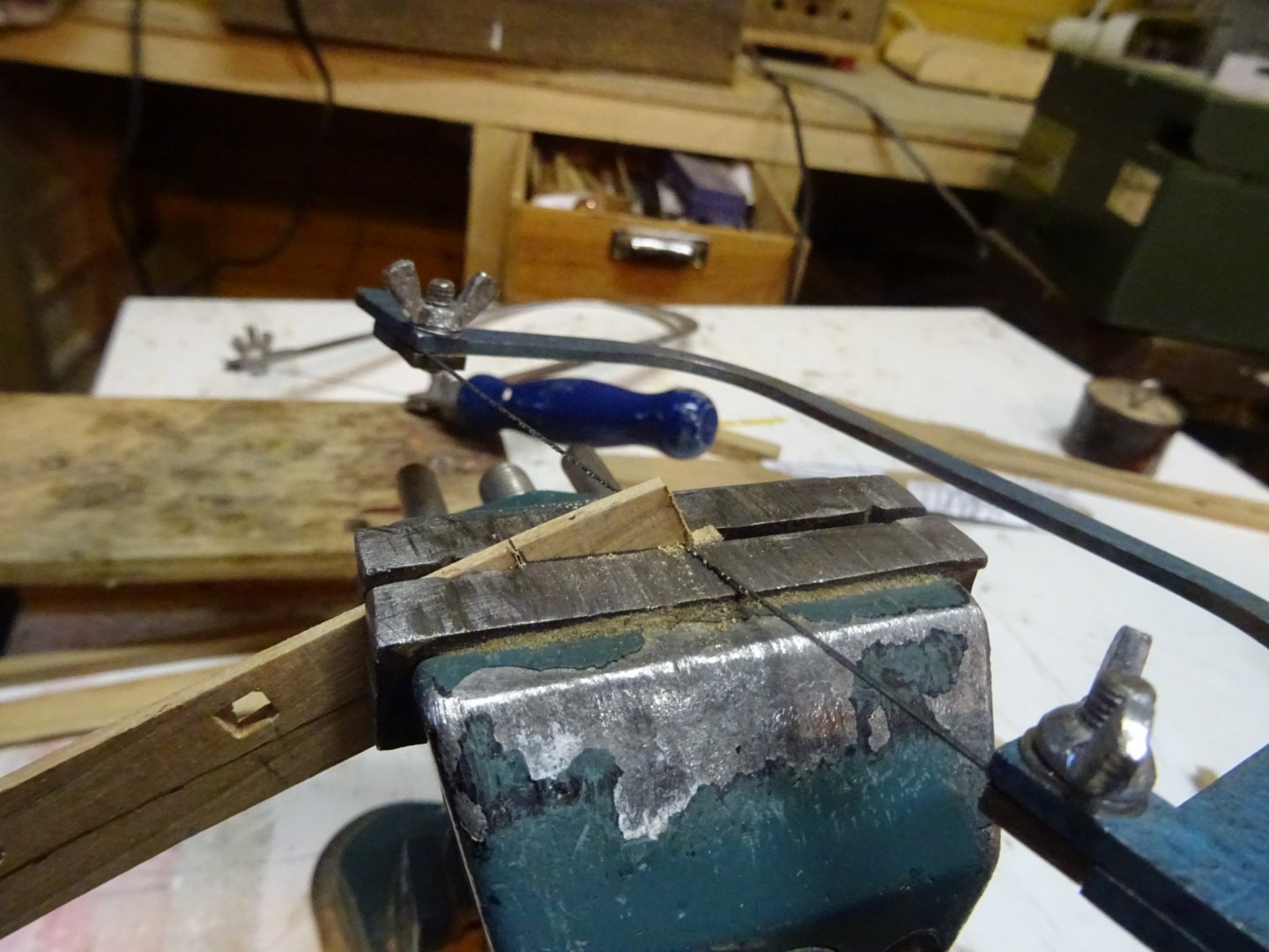

The two pieces waterway fit together.

The two joint of the waterway are finished.


Thank you to follow
Thank you for the likes
Thank you for your constructive comments
Till next week
-
On 2/13/2020 at 8:55 PM, KeithAug said:
Your beautiful work continues - and you seem to progress so quickly.
Thanks Keith.
The progress seems to go quickly because I took some weeks advantage with the build before starting this log. In this way I have always something in spare to report in the weeks when I couldn't work a lot at the model. I like to have a log that steadily progresses. But real time is slowly catching up with me.
It is also a model that builds fast.
- FriedClams and mtaylor
-
2


LANA by mitbok - SMALL - Fictional sandbagger based on ANNIE plans
in - Build logs for subjects built 1851 - 1900
Posted
Just discovered your log on the sandbagger and read throughout . What a beautiful model that you made!