


G.L.
-
Posts
1,553 -
Joined
-
Last visited
Content Type
Profiles
Forums
Gallery
Events
Posts posted by G.L.
-
-
-
8. Accessories
The handout of Mr Van Beylen doesn't give a lot of information about the boats' inventory. Therefore he refers to an article about American whaleboats of Mr E.W. Petrejus in a magazine 'de Modelbouwer' in 1950. Unfortunately the article is not included in the handout though it is published by the same publisher: de Nederlandse Vereniging voor Modelbouwers.
Luckily for me there is a wealth of information to be found in the book 'Modelmaker's guide 'To build a whaleboat'' by E.A.R. Ronnberg, Jr and in the study 'The whaleboat' by W.D Ansel.
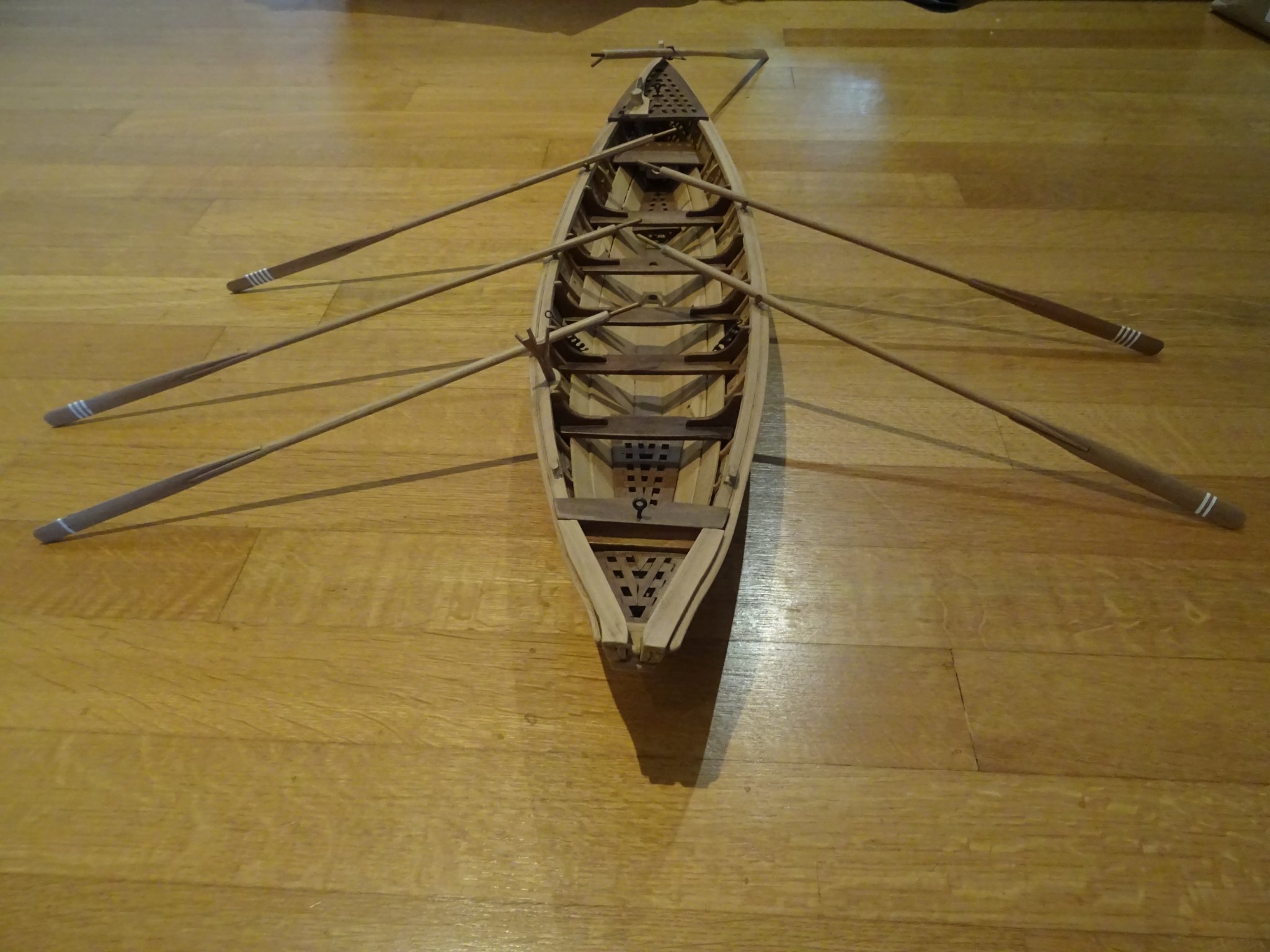
It is almost unbelievable that is was possible to row those boats with all that equipment on board. There is hardly space for the six-men crew.8.1 The harpoons and the lances.
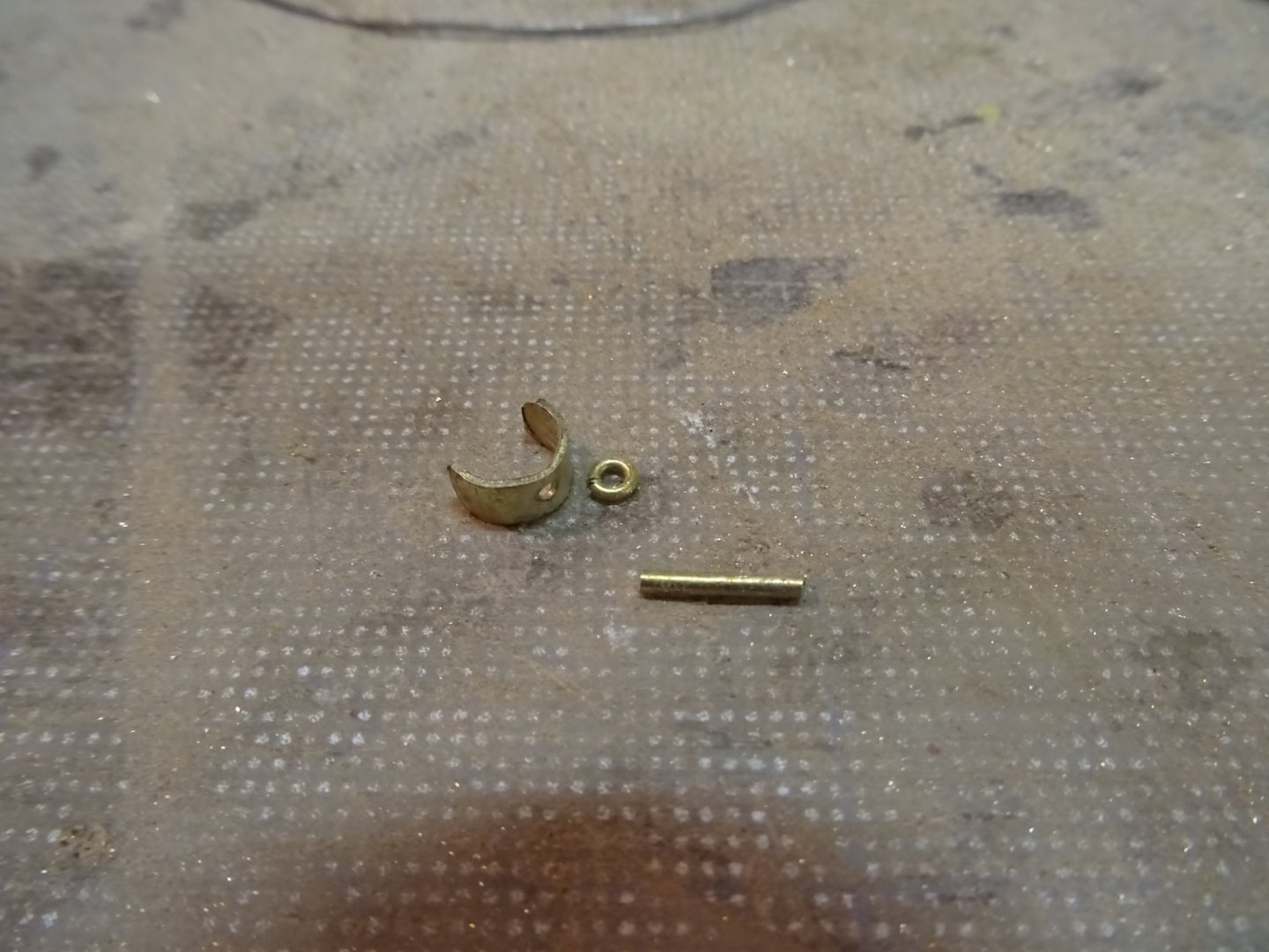
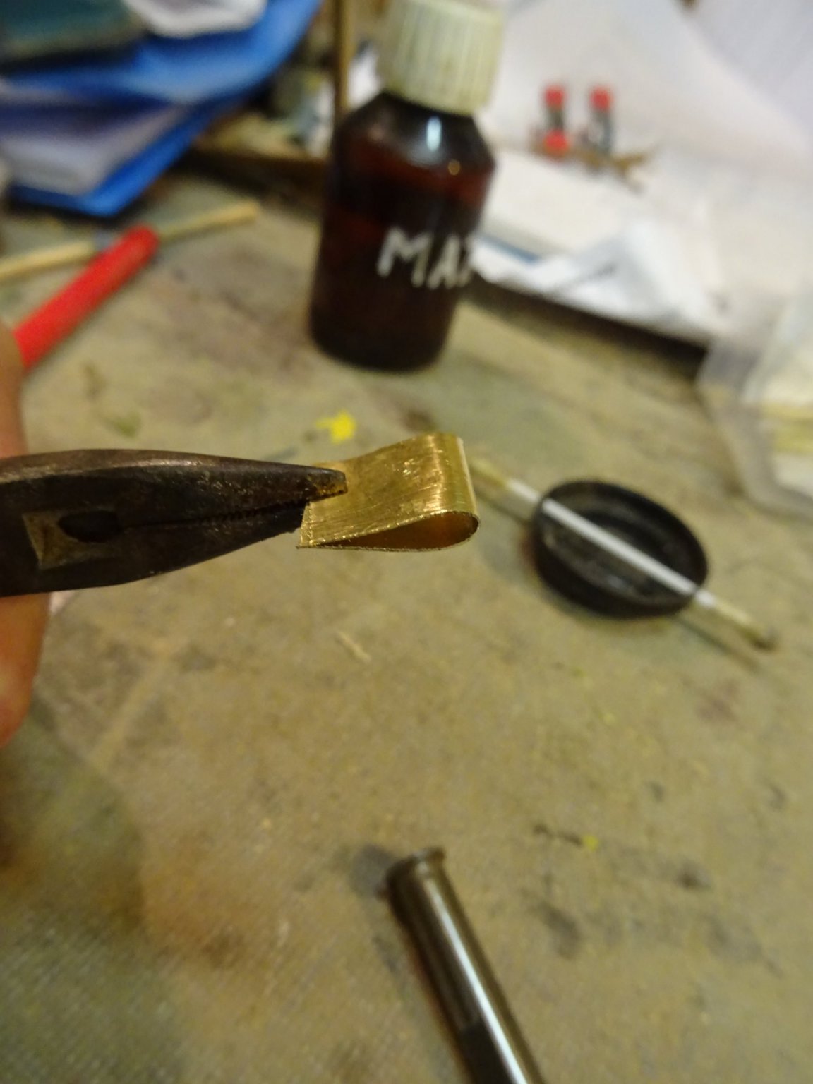
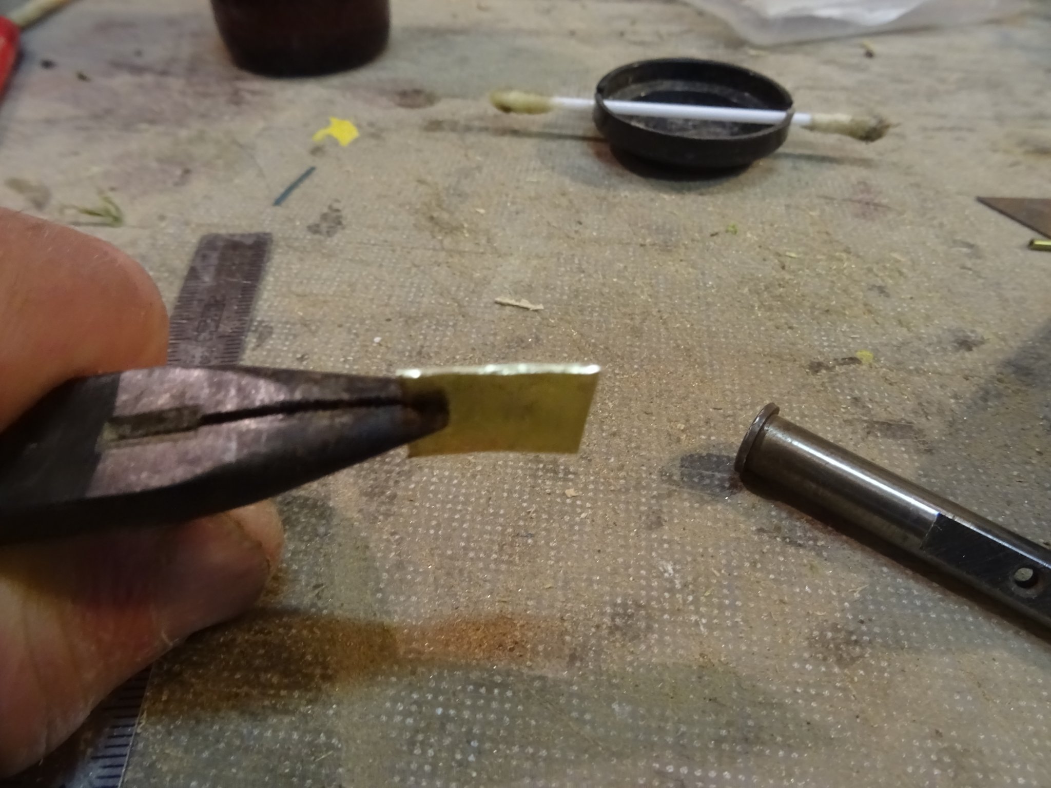
I think that the harpoon was the most important piece of the equipment on board of the boat, so I start with that.To make the blade I fold a small piece of brass in two.


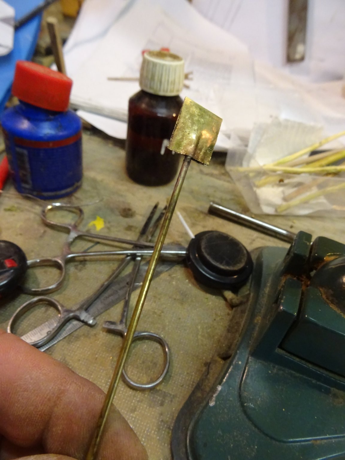
I solder it on a brass shaft.
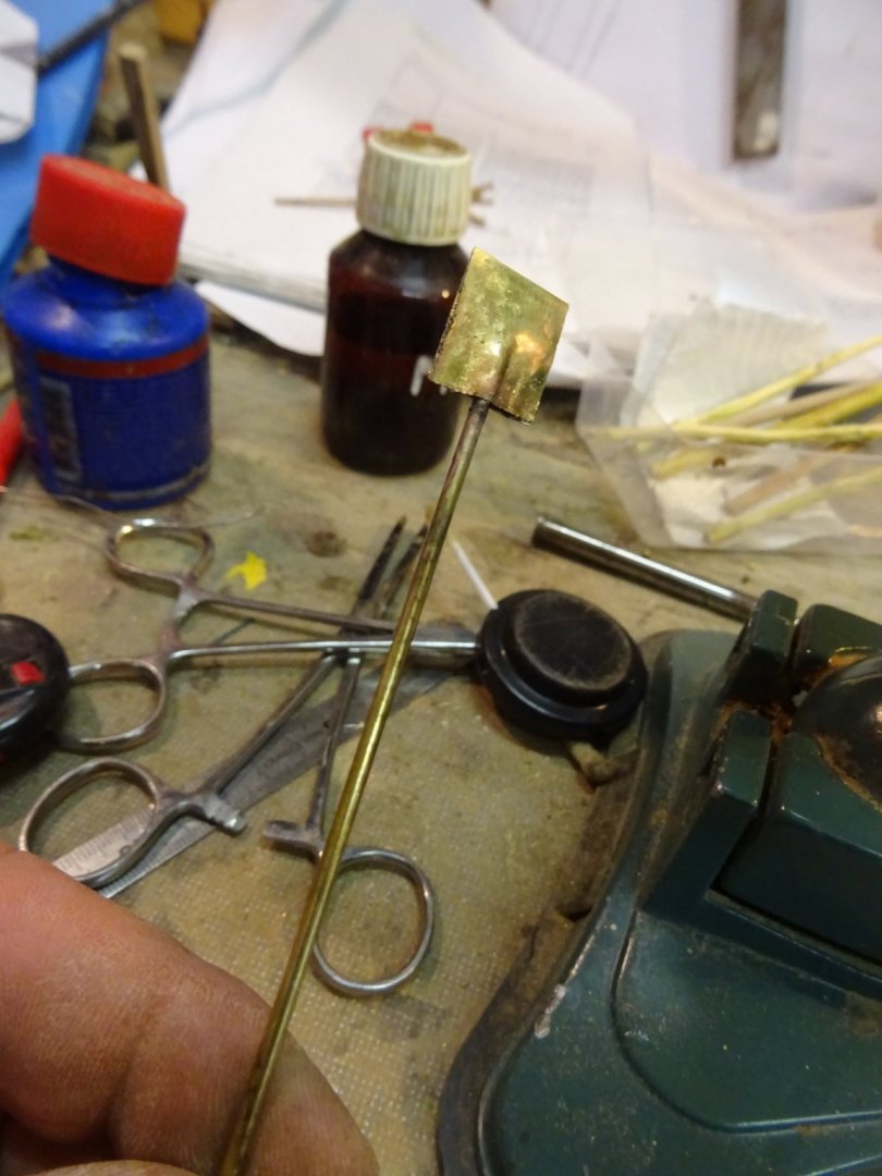
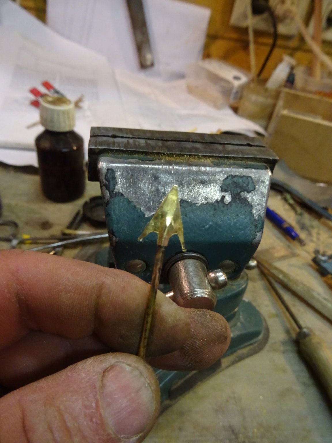
and I saw and drill the iron barbed point.
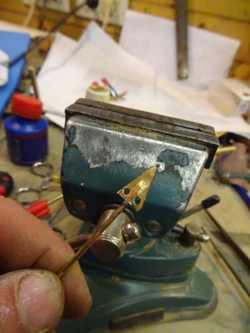

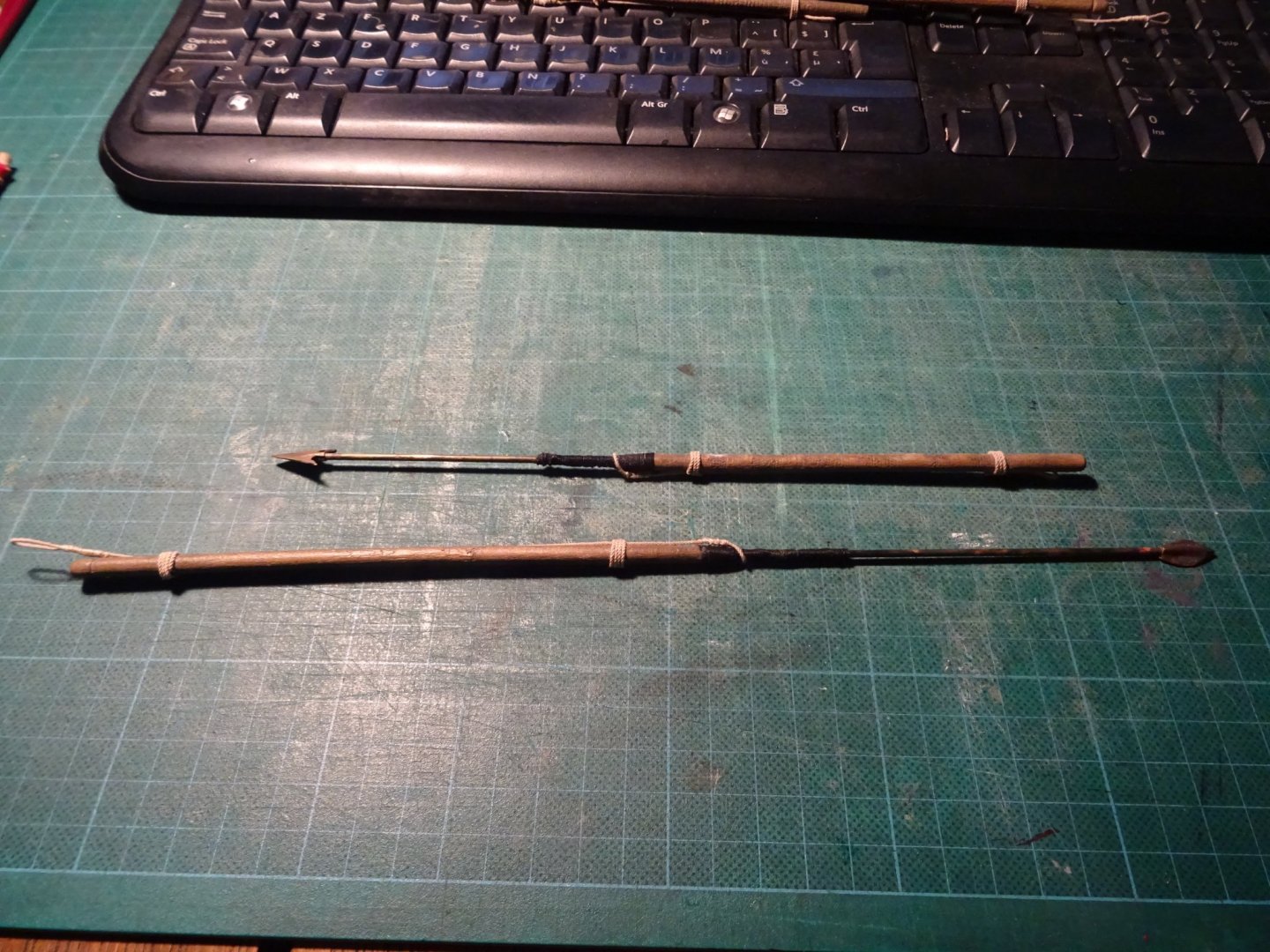
Finally the metal piece is placed on a wooden shaft with a rope to connect the harpoon line.
The lances are made in the same way like the harpoons. They don't have barbs and they are longer. The lances are used to kill the whale at the end of the hunt. They are thrown into the whale and pulled out again and again, and at the end the whale is also receiving the deathblow with the lance.
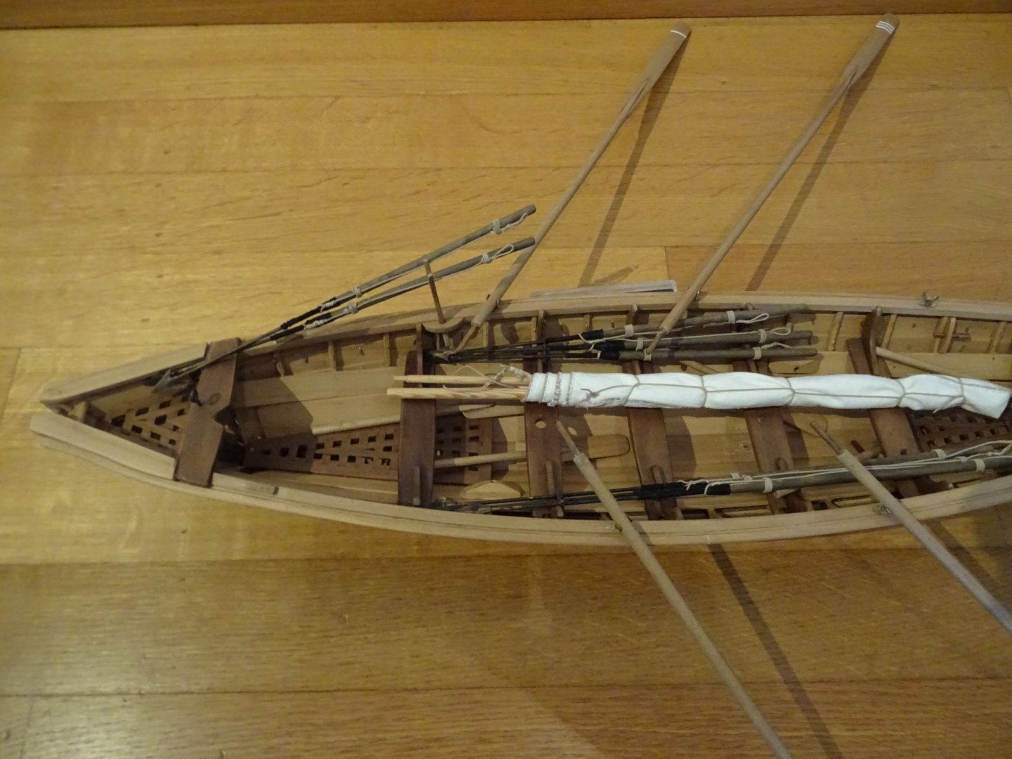
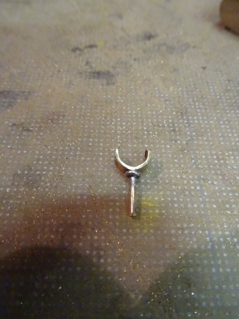
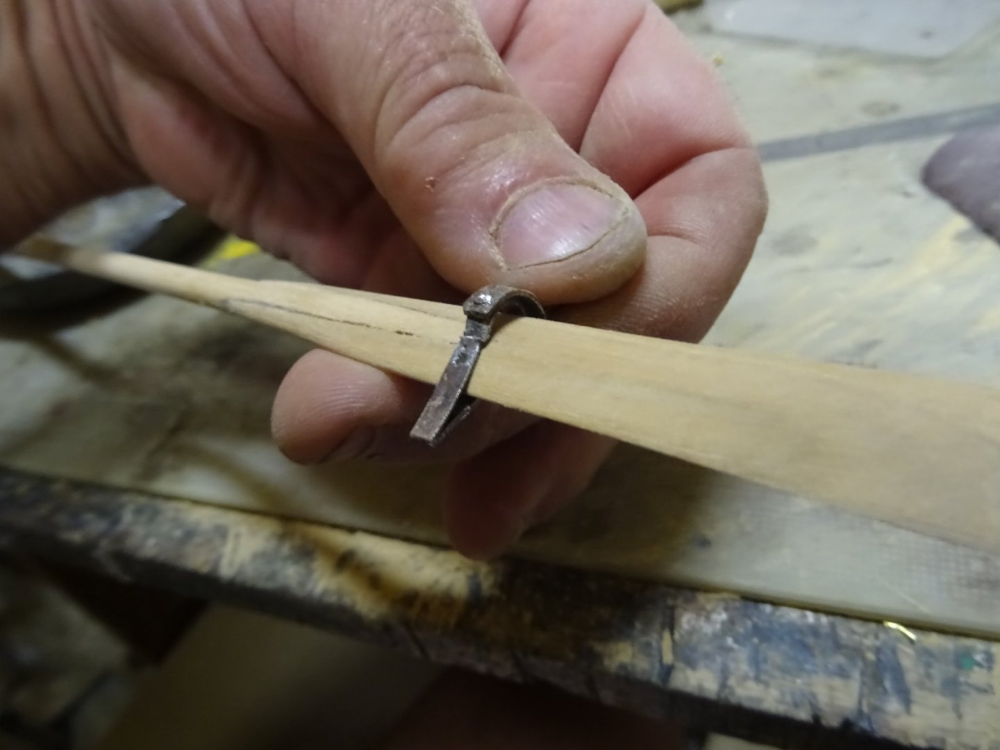
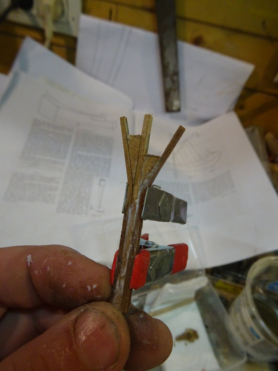
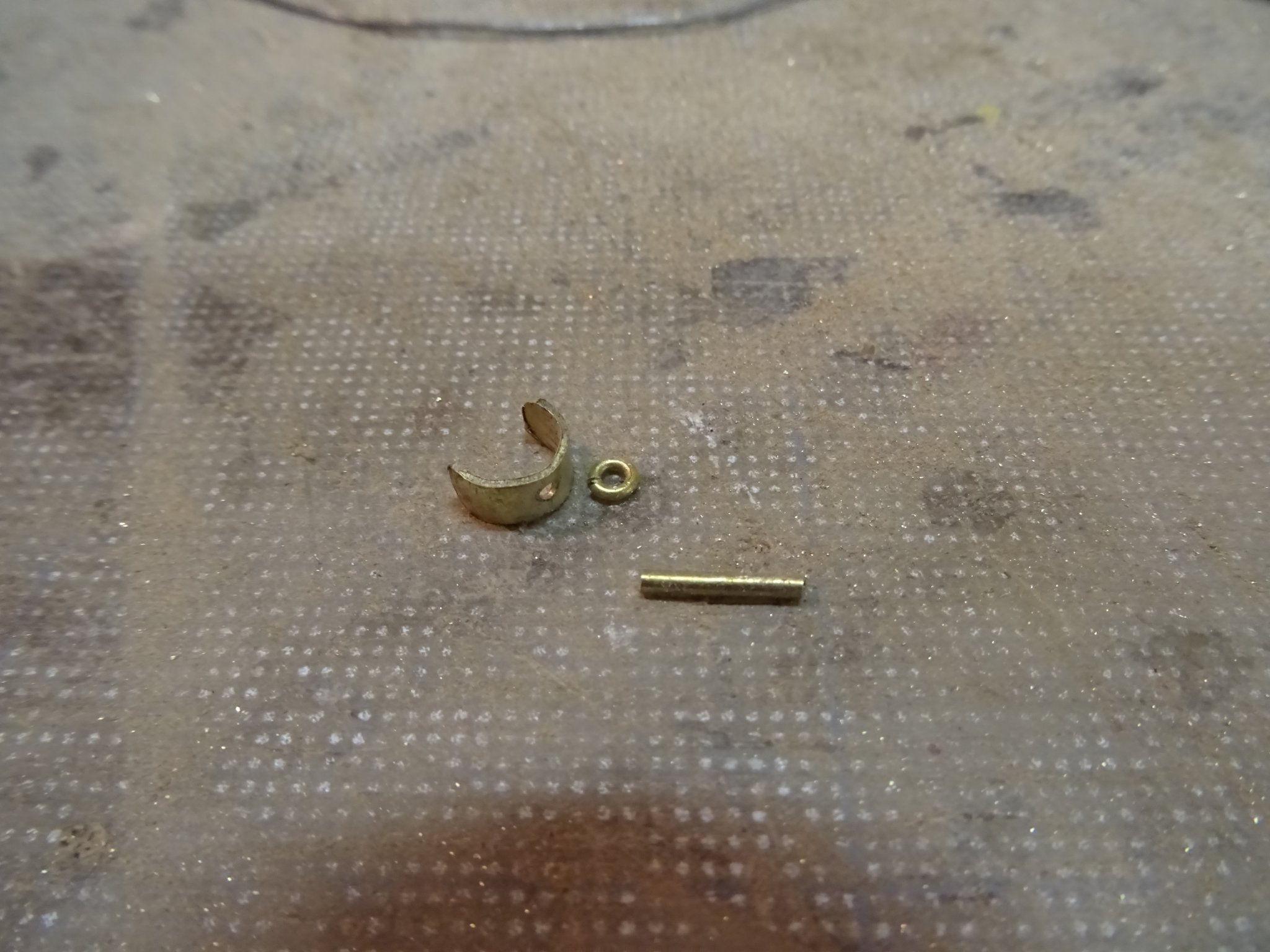
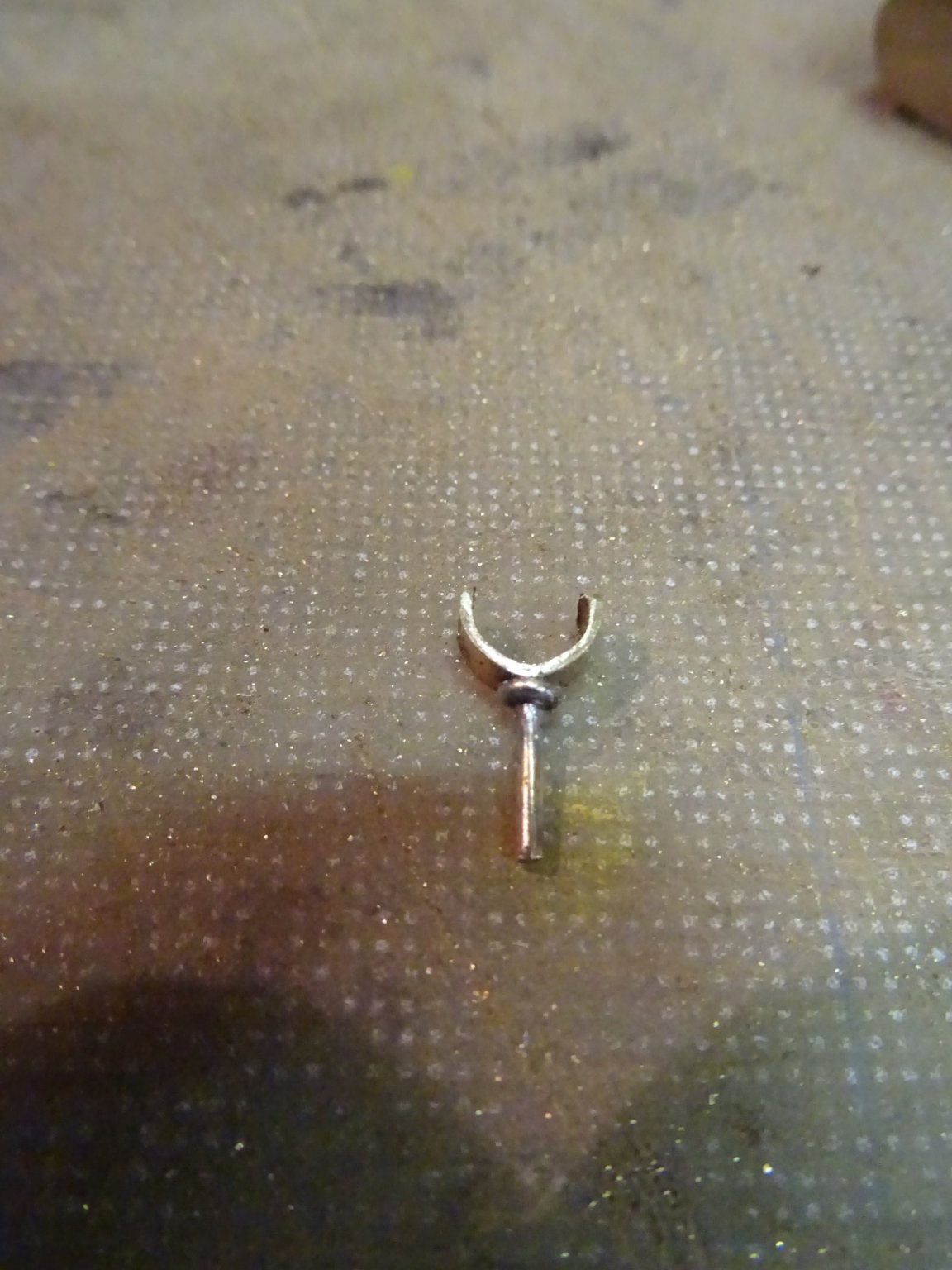
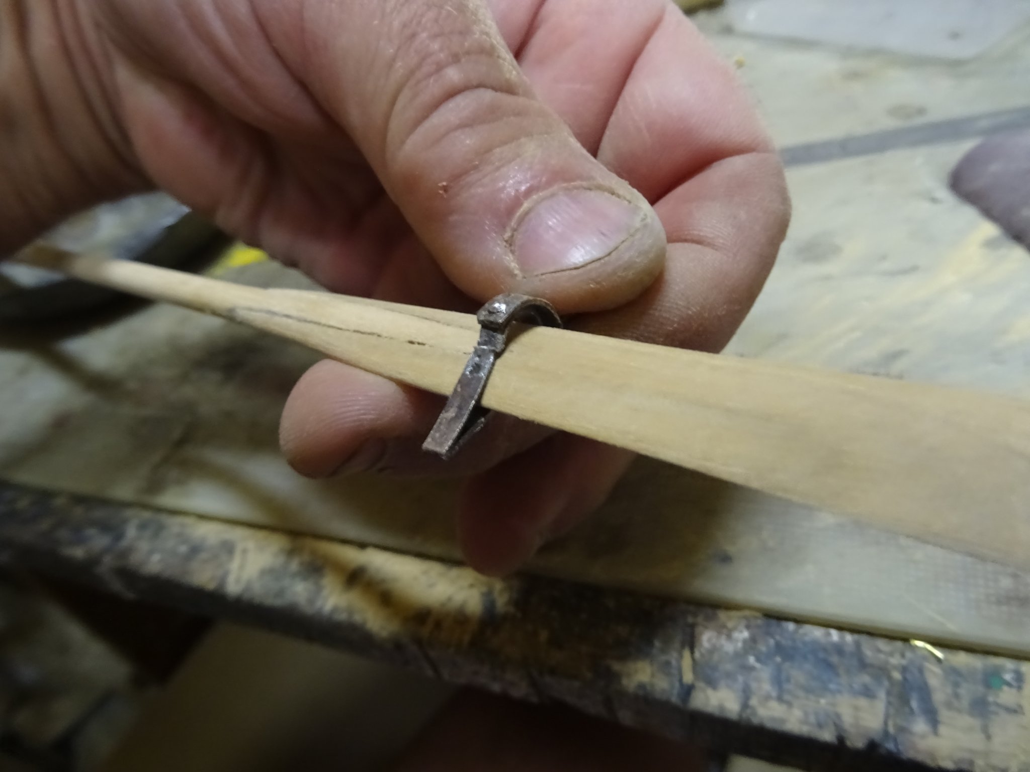
Two of the harpoons can be laid in the harpoon crotch. That is sort of fork wit three teeth.
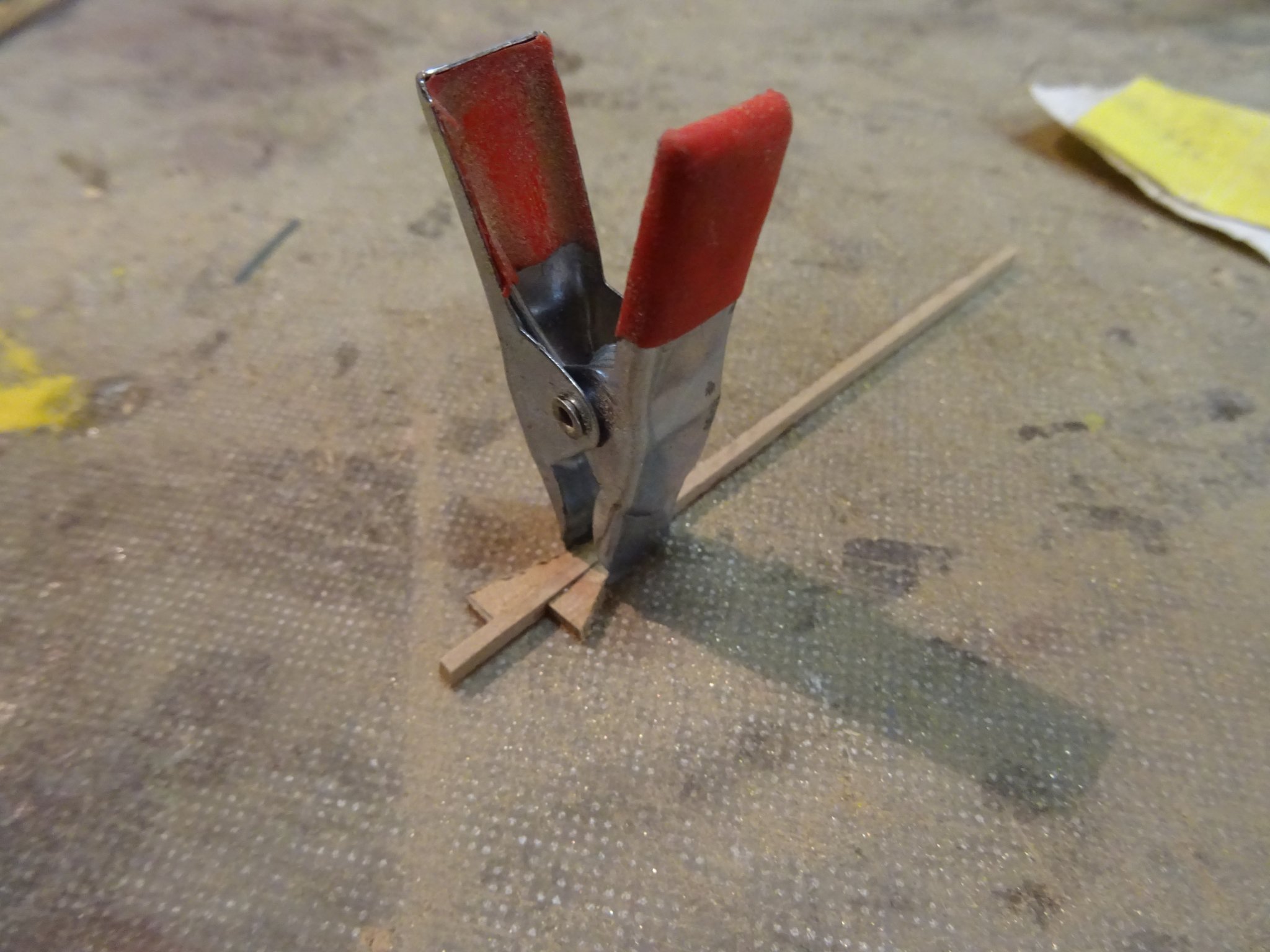
Making the crotch:


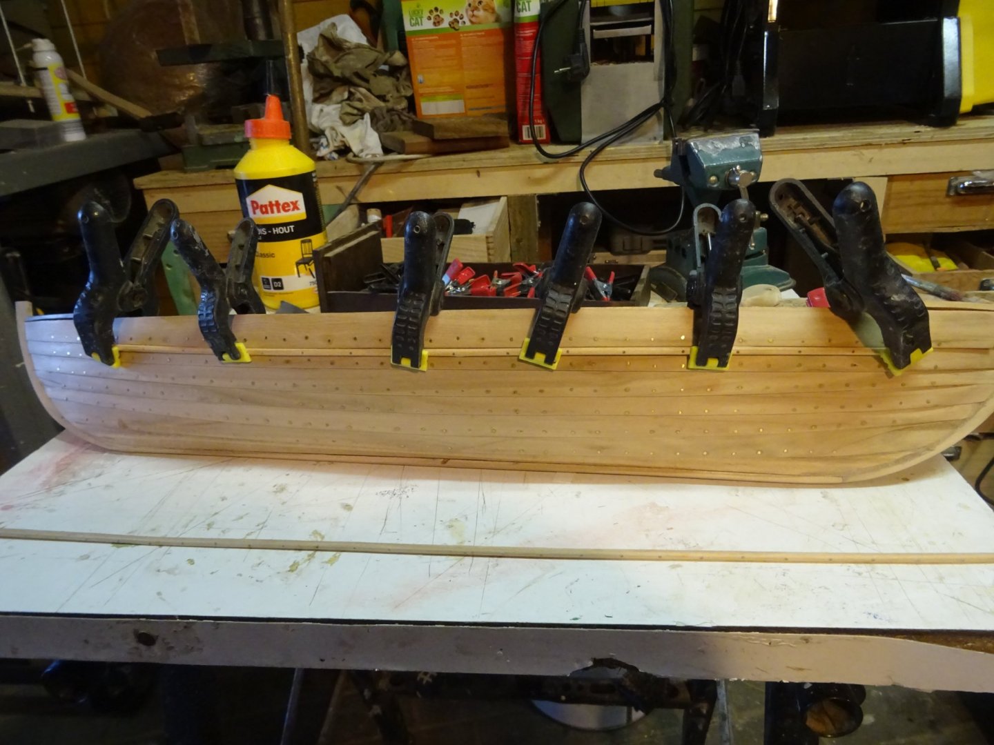
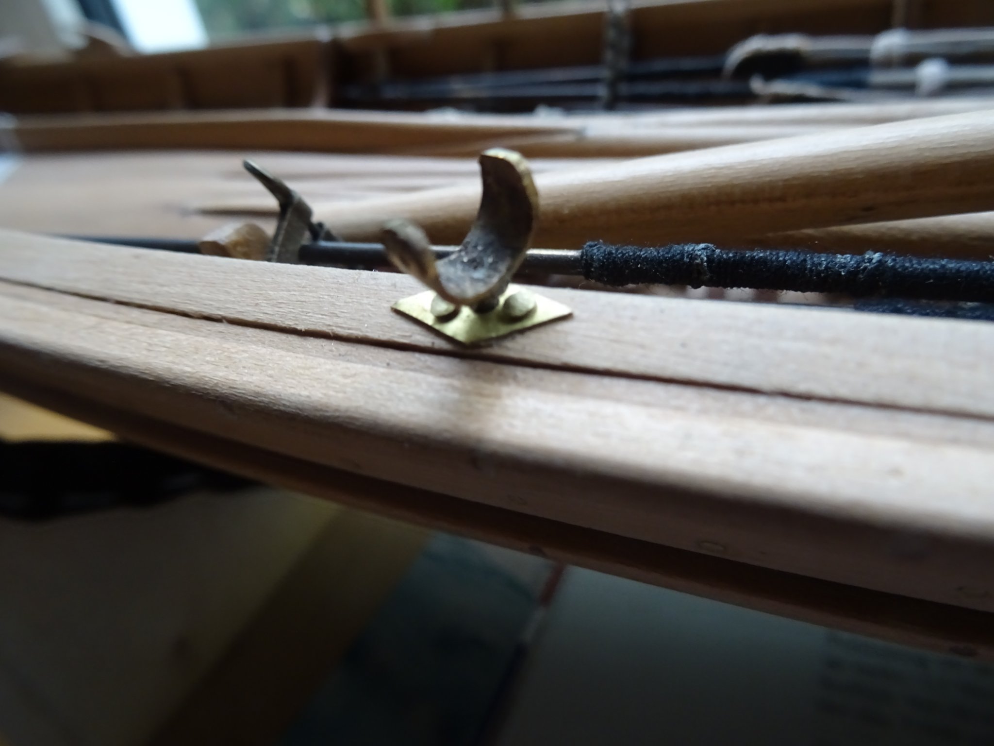
On my model are five harpoons at starboard side: two ready for use in the crotch and three reserve harpoons in the rack.
At portside are three lances in the rack.
Thank you very much for reading this log and for your likes.
Till next week and Merry Christmass for you all!
-
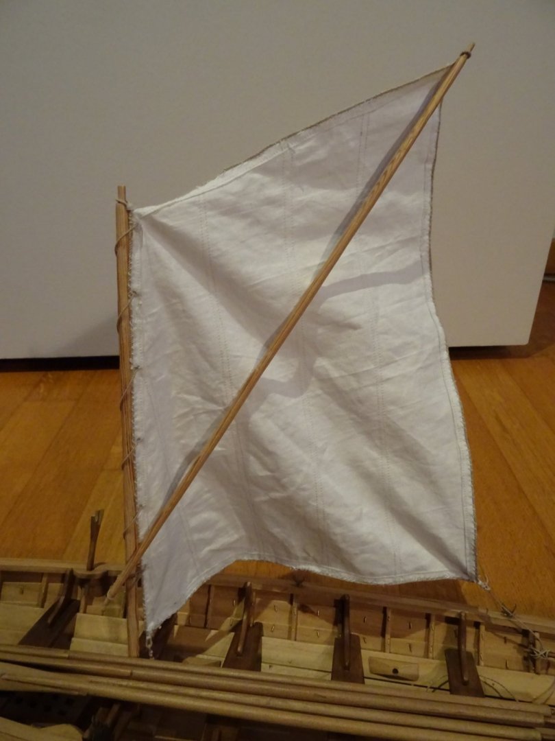
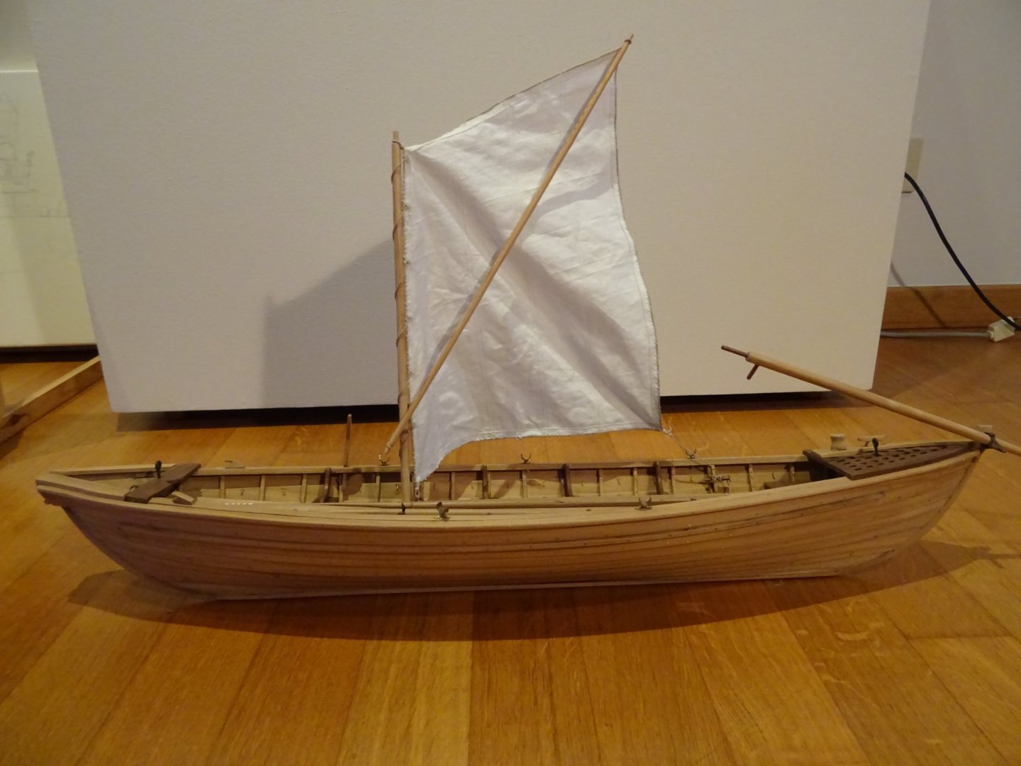
7.1 Mast and sail
With suitable wind, the boat could be sailed. Therefore it was equipped with a thrust mast, a gaff and a sail.
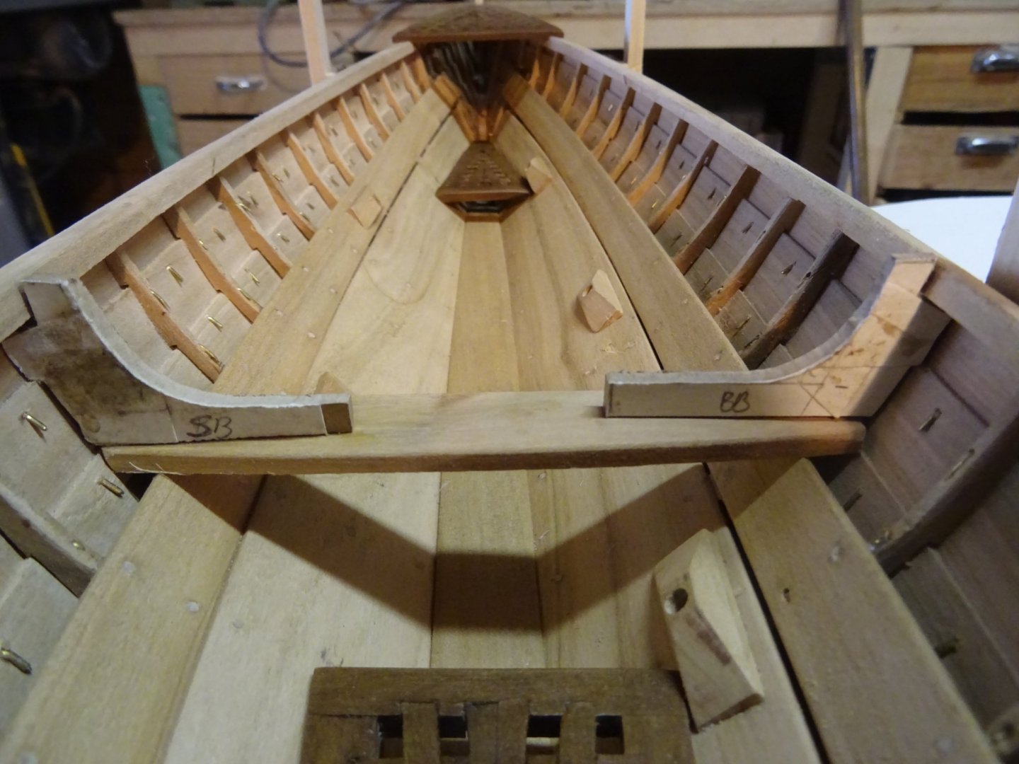
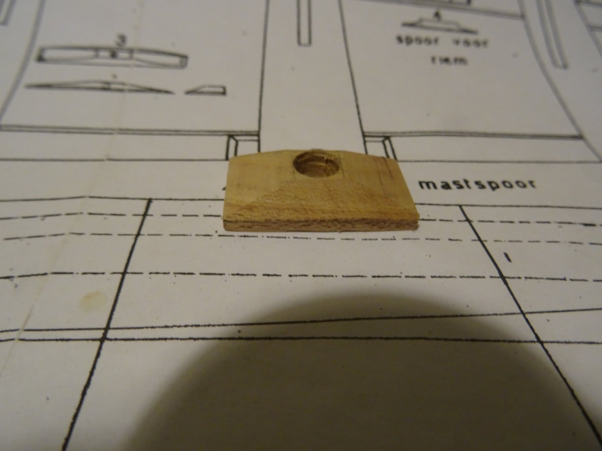
Looking more close to the sail plan of the boat, I discovered an error in the drawing of Mr. Van Beylen and I walked with my eyes open into that error. On the plan the mast thwart is drawn as the second aft thwart of the boat. In the model which stood model for the drawing, the mast is standing in the second thwart from before.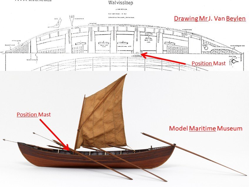
Stupid of me, I should have seen it. I should at least have questioned the position afterward, all the more because I have photos of the original model.
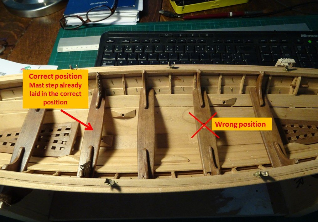
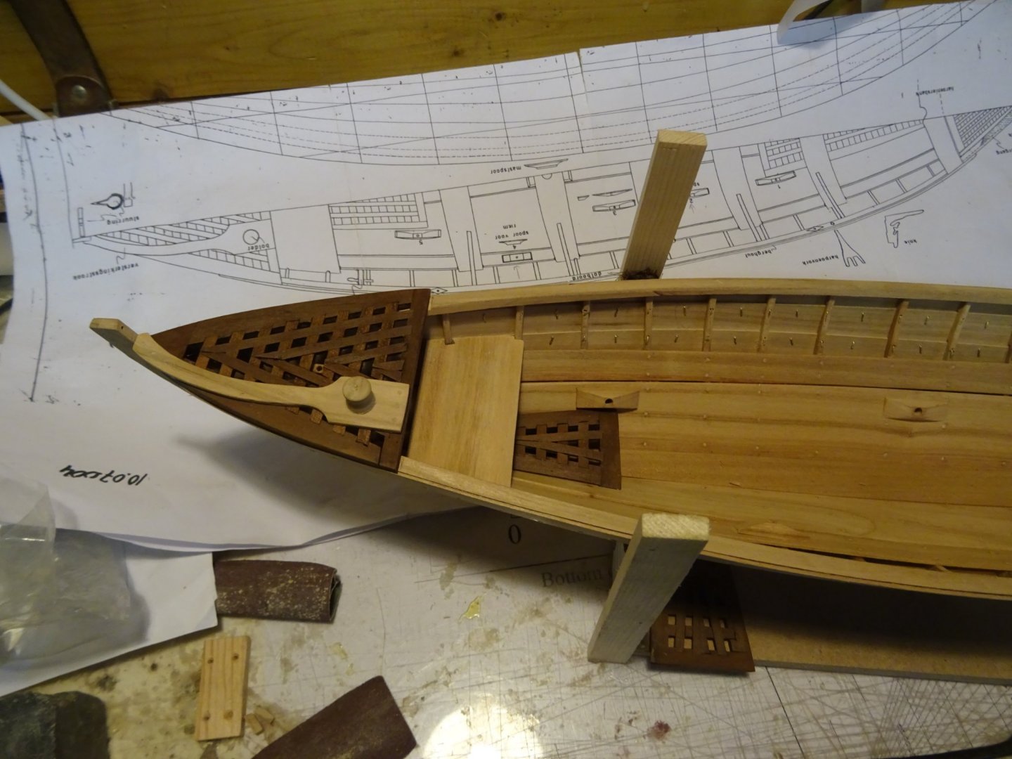
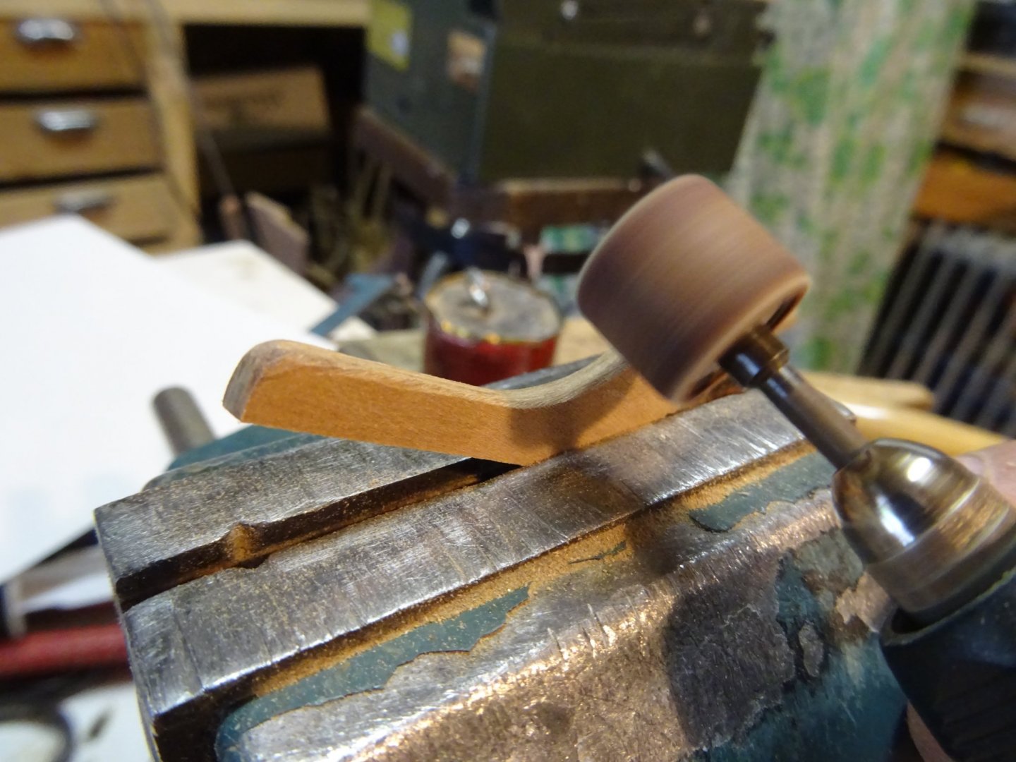
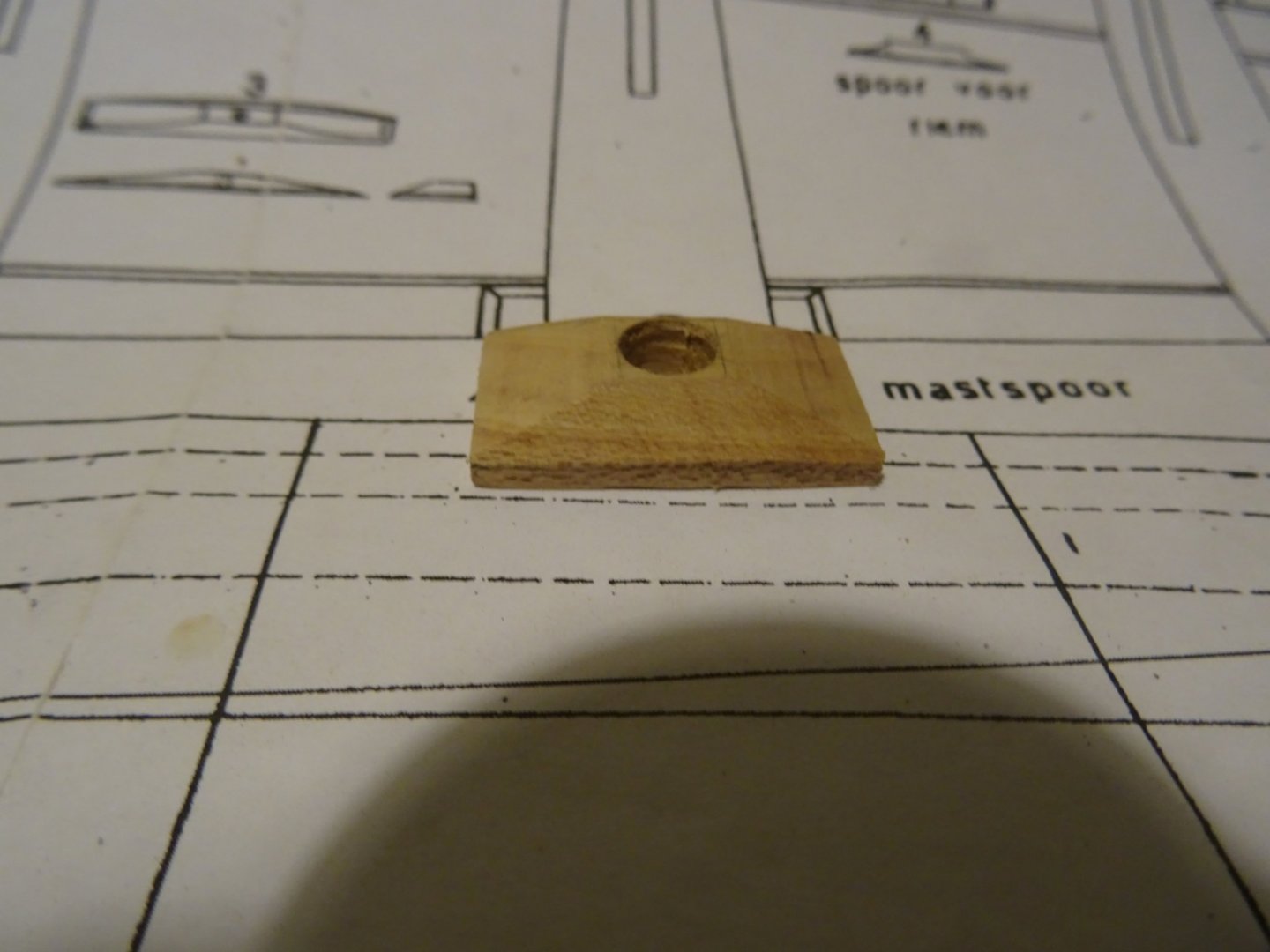
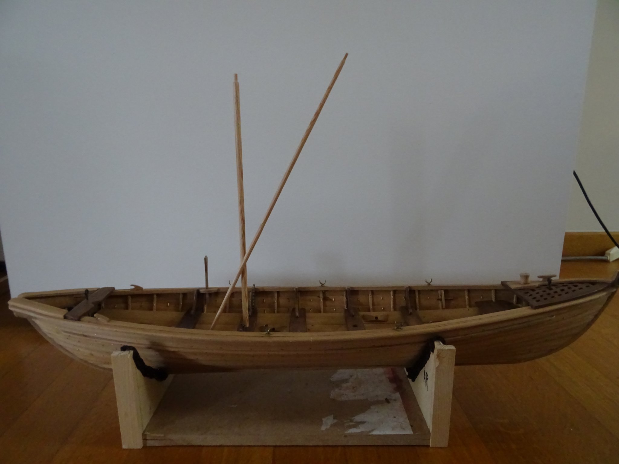
Luckily I can detach the mast step without damaging the bottom board. I glue it into the correct position and drill a hole in the correct mast thwart. I don't know yet if I will close the hole in the aft thwart. The scar will remain visible. When the boat will be loaded with all the equipment the hole may not be noticeable at all.Mast and gaff are made of pine in the same way like I made the shafts for the oars. On the picture the gaff is not yet placed correctly. It is simply standing with one end in an opening of the grating.

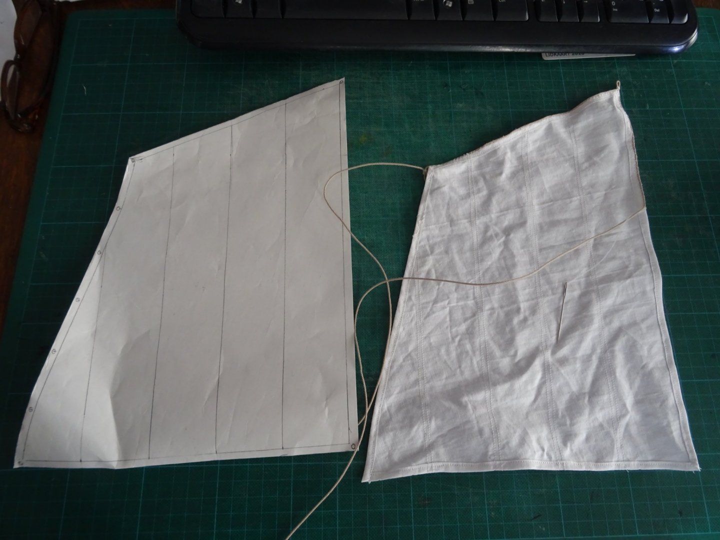
To be able to cut the sail, I make a paper template and fit it on the model.

I was a bit lazy in making photos of the sewing of the sail but I used the same method as described in more detail in my gaff sailboat log
Here you see the sail next to the template while sewing the bolt rope.
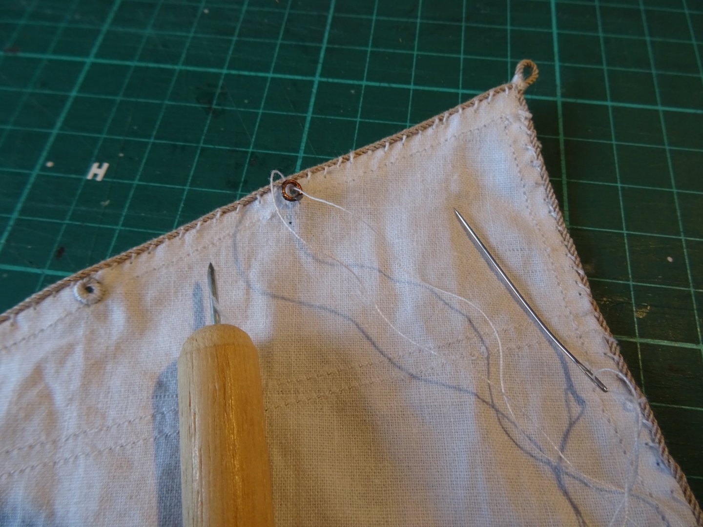
I make cringles by poking a hole through the sail with an owl. Then I put a copper ring over the hole en sew it all over. On the right the cringle before the sewing starts, on the left a finished cringle.
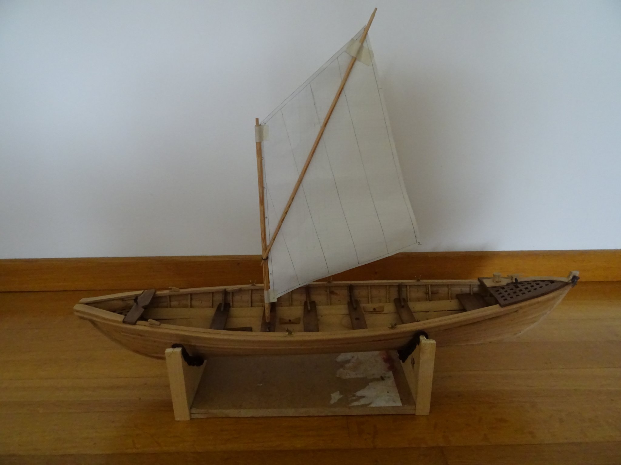
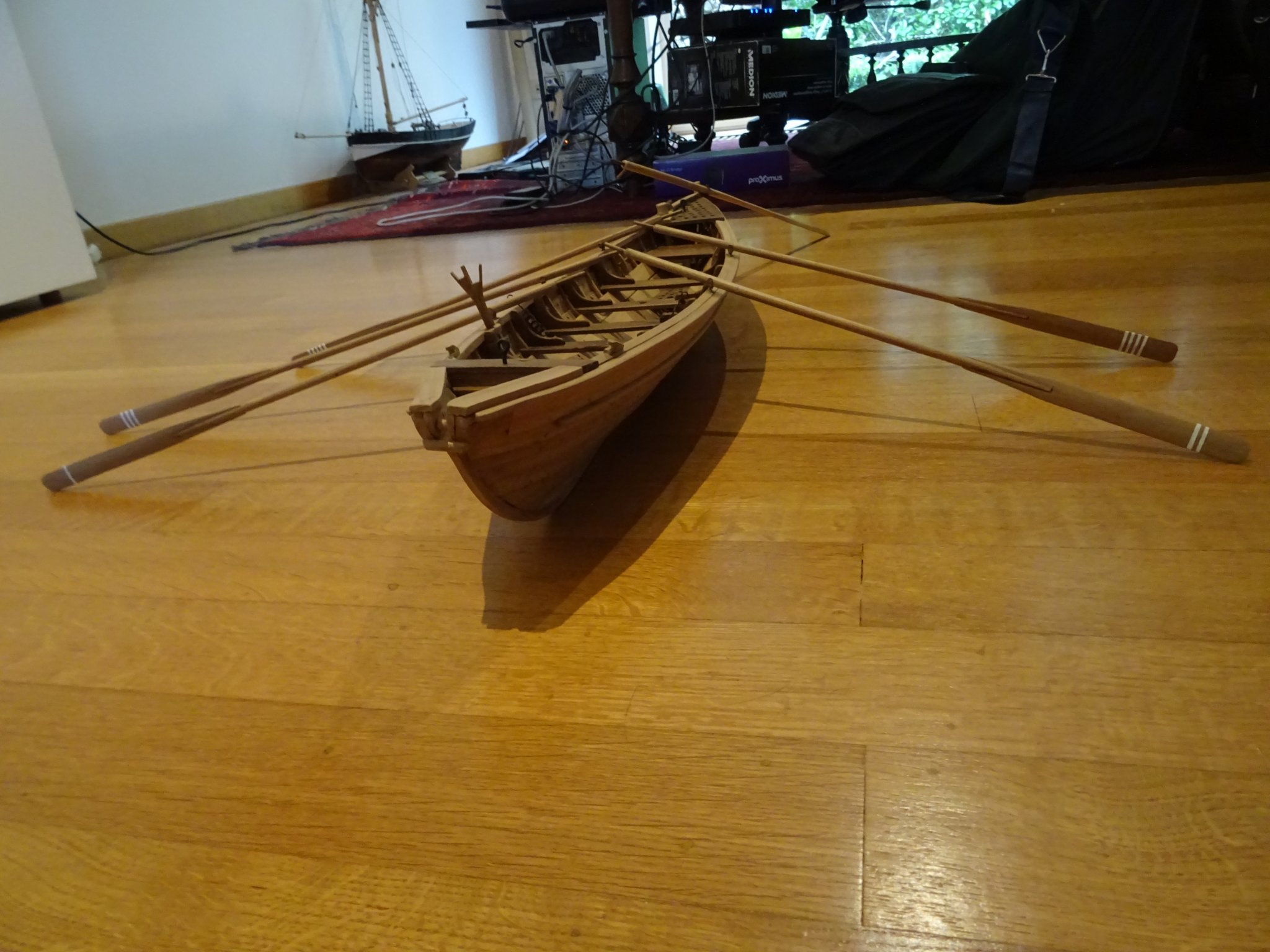
Here is the boat rigged for sailing. These are probably the last pictures with the sail because I intend to present the boat ready for launching from the mother ship. To be honest, I don't find her that elegant under sail.
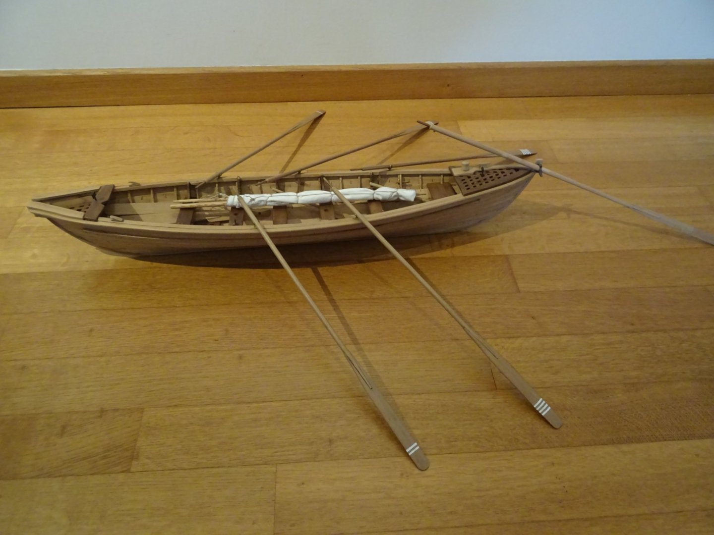
The boat with the sail stowed away.
Thank you very much for reading this log and for your likes.
Till next week!
- bruce d, GrandpaPhil, mtaylor and 5 others
-
 8
8
-
Mike, That's realy a beautiful model and very inspiring display. Congratulations!
-
7.2 The paddles
Rowing with oars makes a lot of noise and can be heard by a whale from a long distance. When a boat skipper thinks that the whale is unaware of the presence of the boat, he orders paddling as not to warn the whale.
The making of the paddles is the same as for the oars.


The paddles in the boat

Oars and paddles in the boat.
Thank you very much for reading this log and for your likes.
Till next week!
- bruce d, mtaylor, Ainars Apalais and 5 others
-
8
-
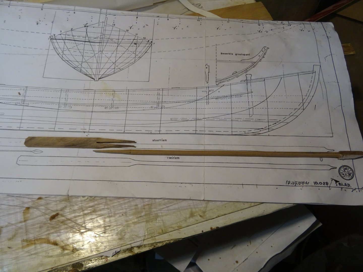
7. Propulsion
The whaleboat was in general propelled by manpower. This means with the help of oars. When the wind was suitable there was a thrust mast aboard with a small sail. As the boat has no center board I assume that the sail was not often used. Only maybe with running and broad wind.7.1 The oars
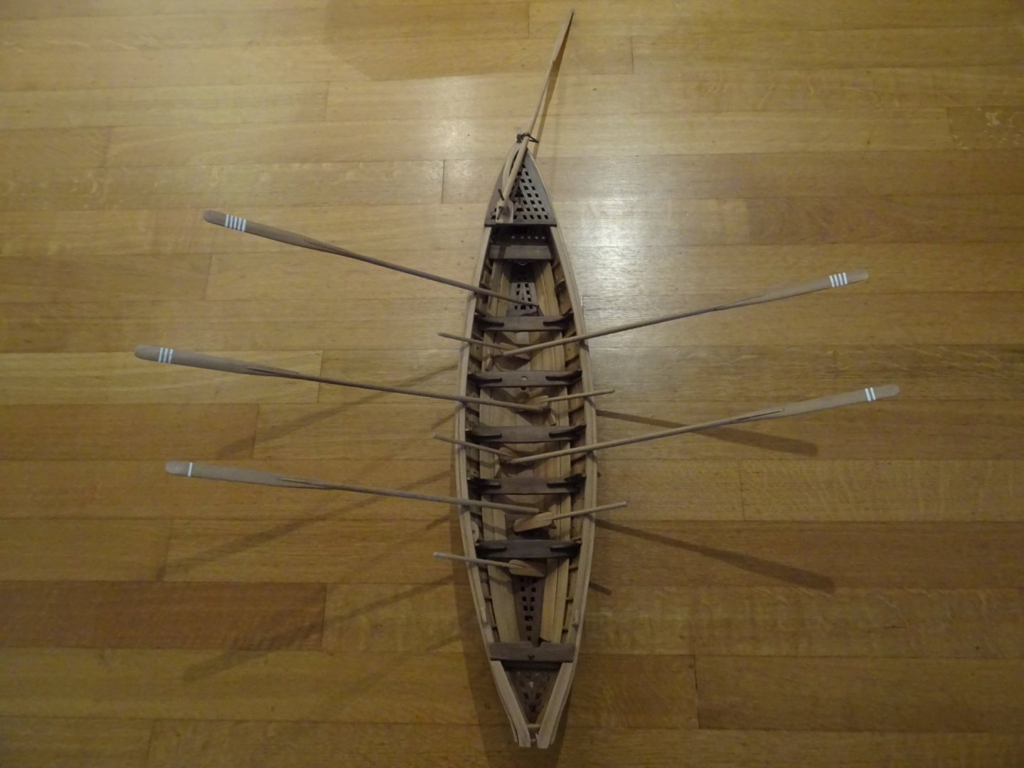
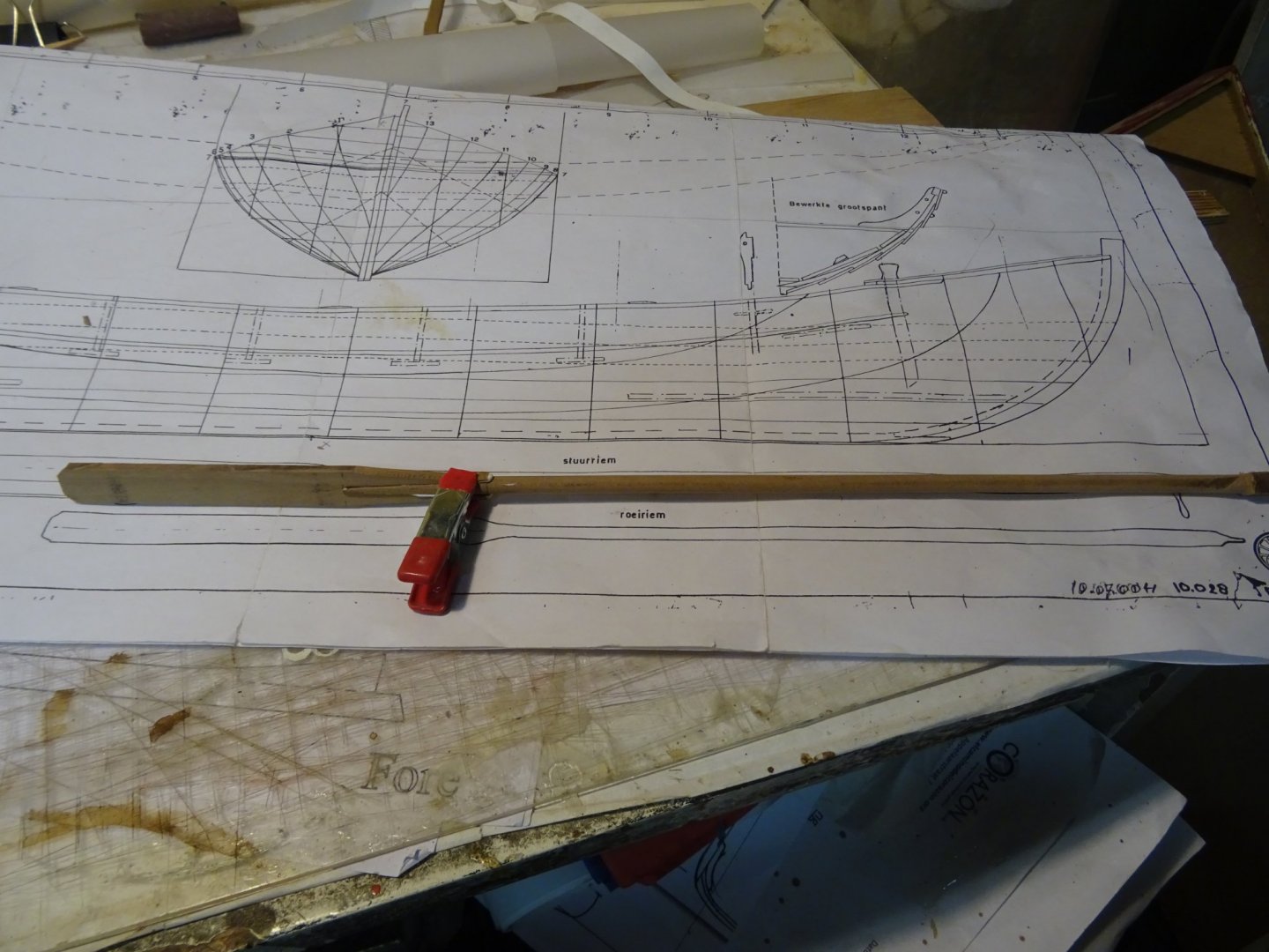
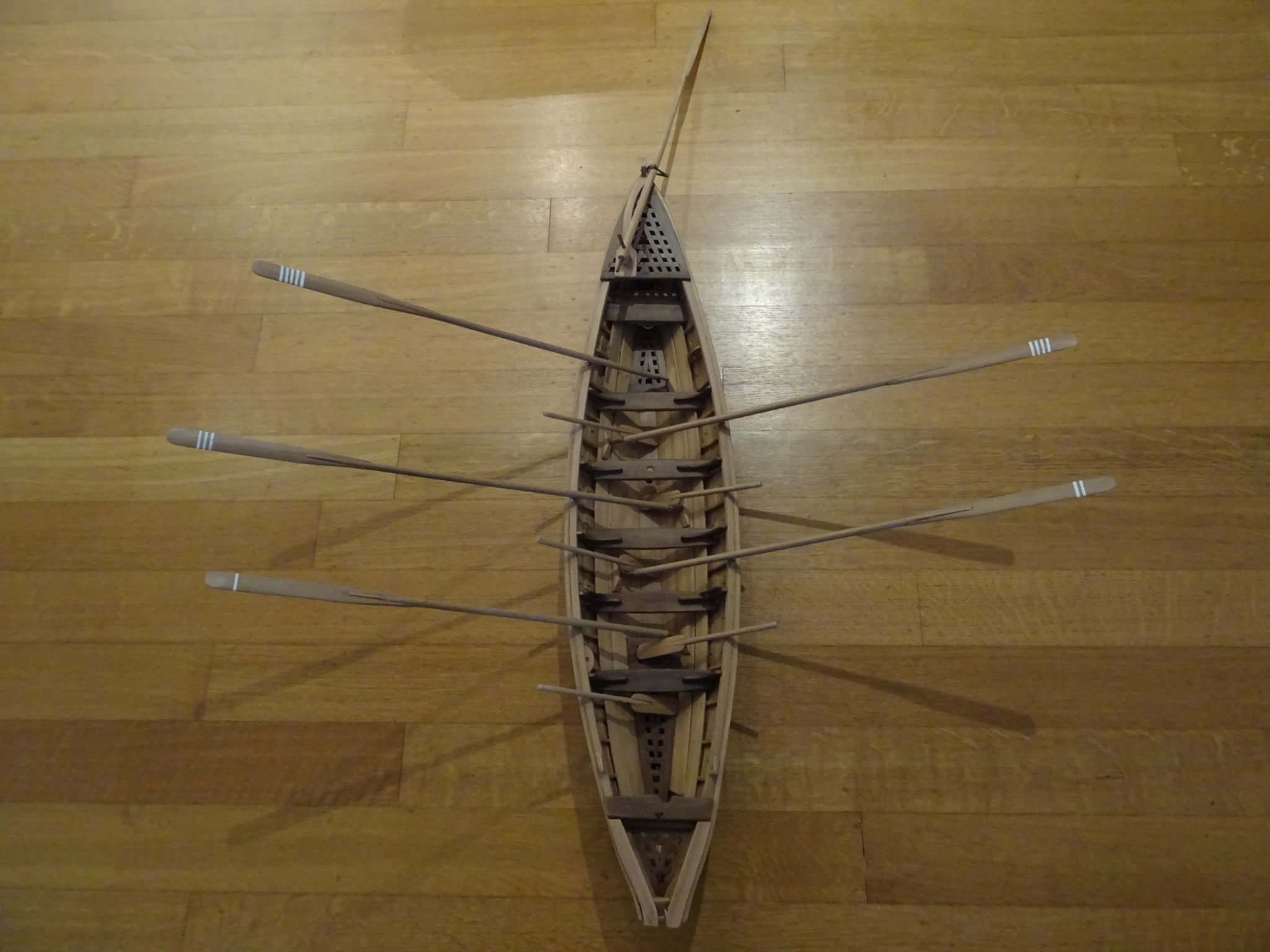
The boat is rowed by five oarsmen, three at starboard side and two at port side. To compensate for the uneven distribution, the five oars are of different lengths and they all have their own position in the boat.
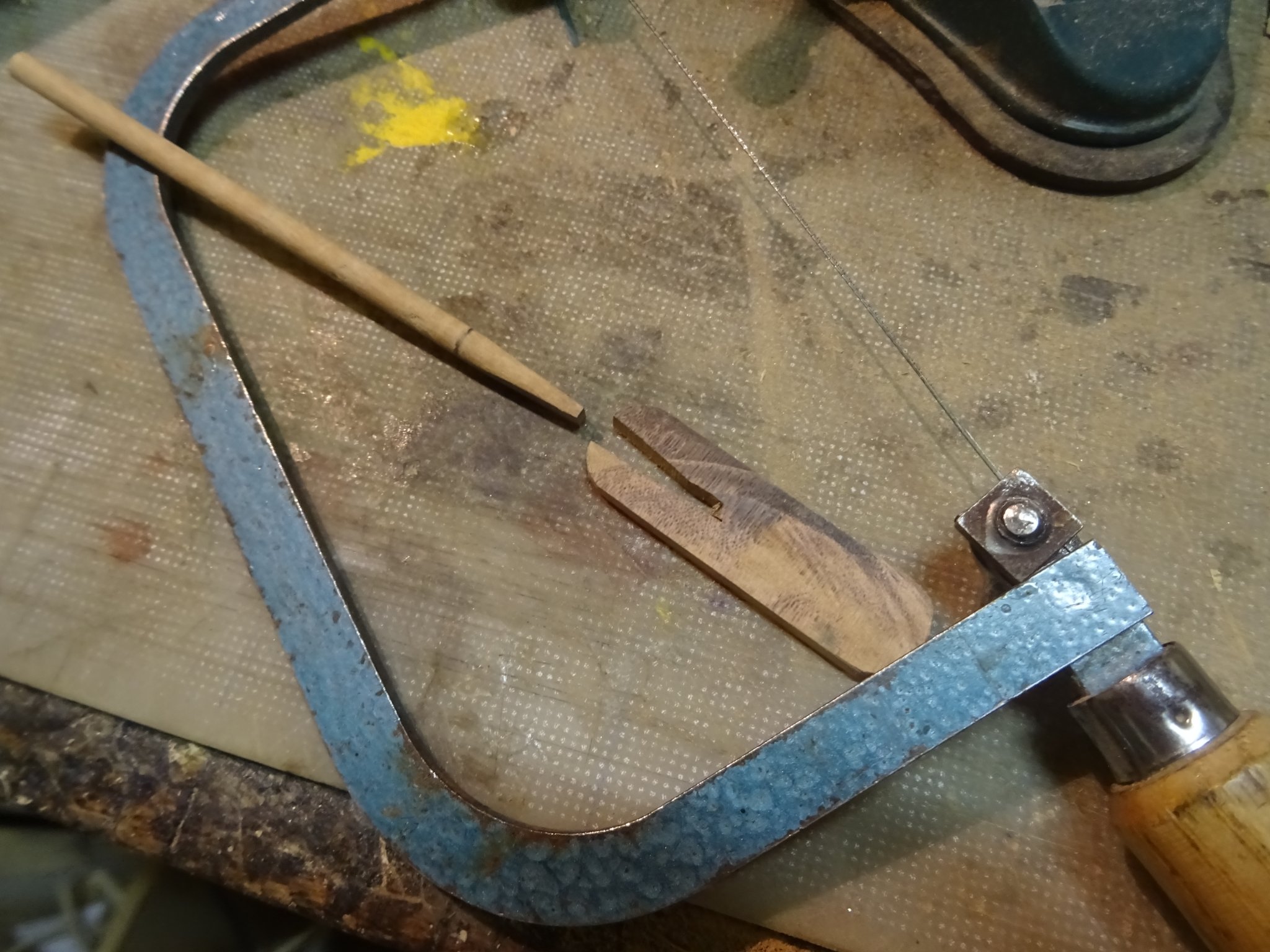
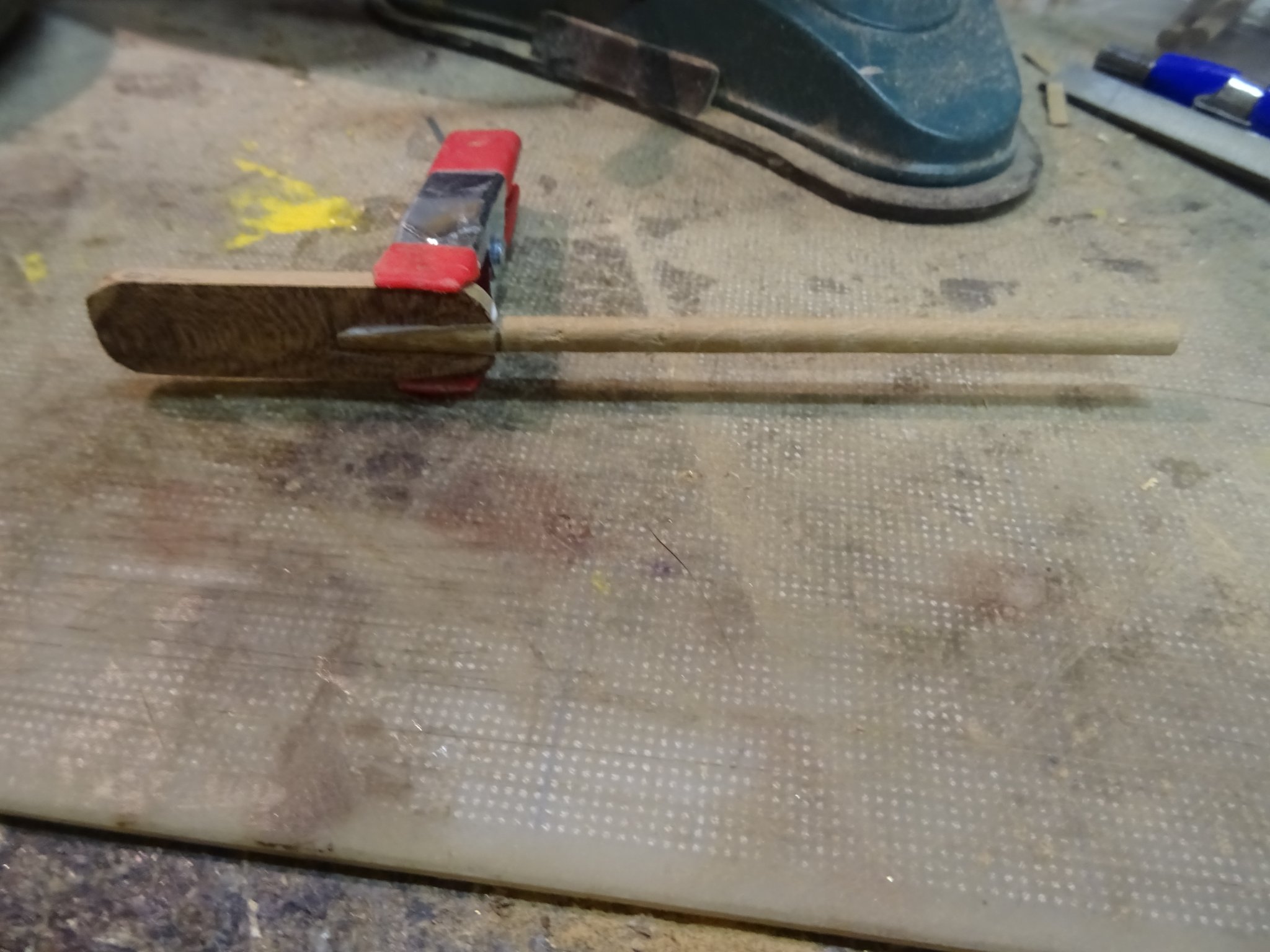
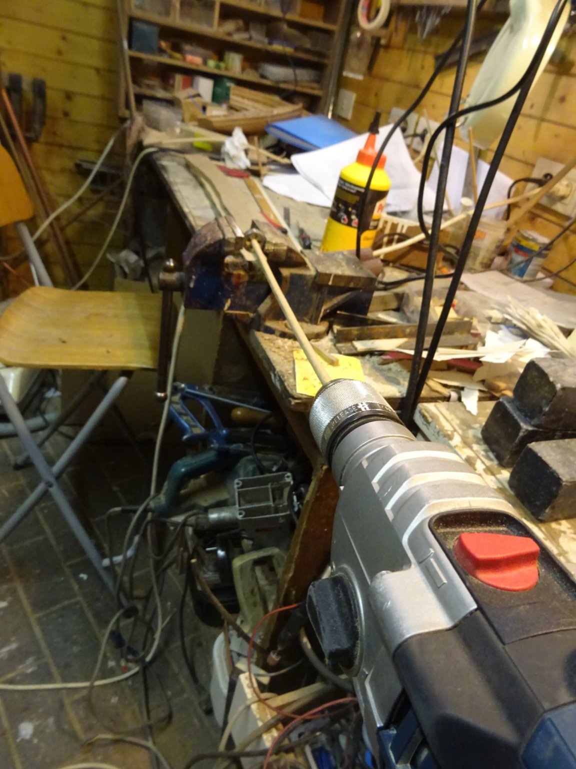
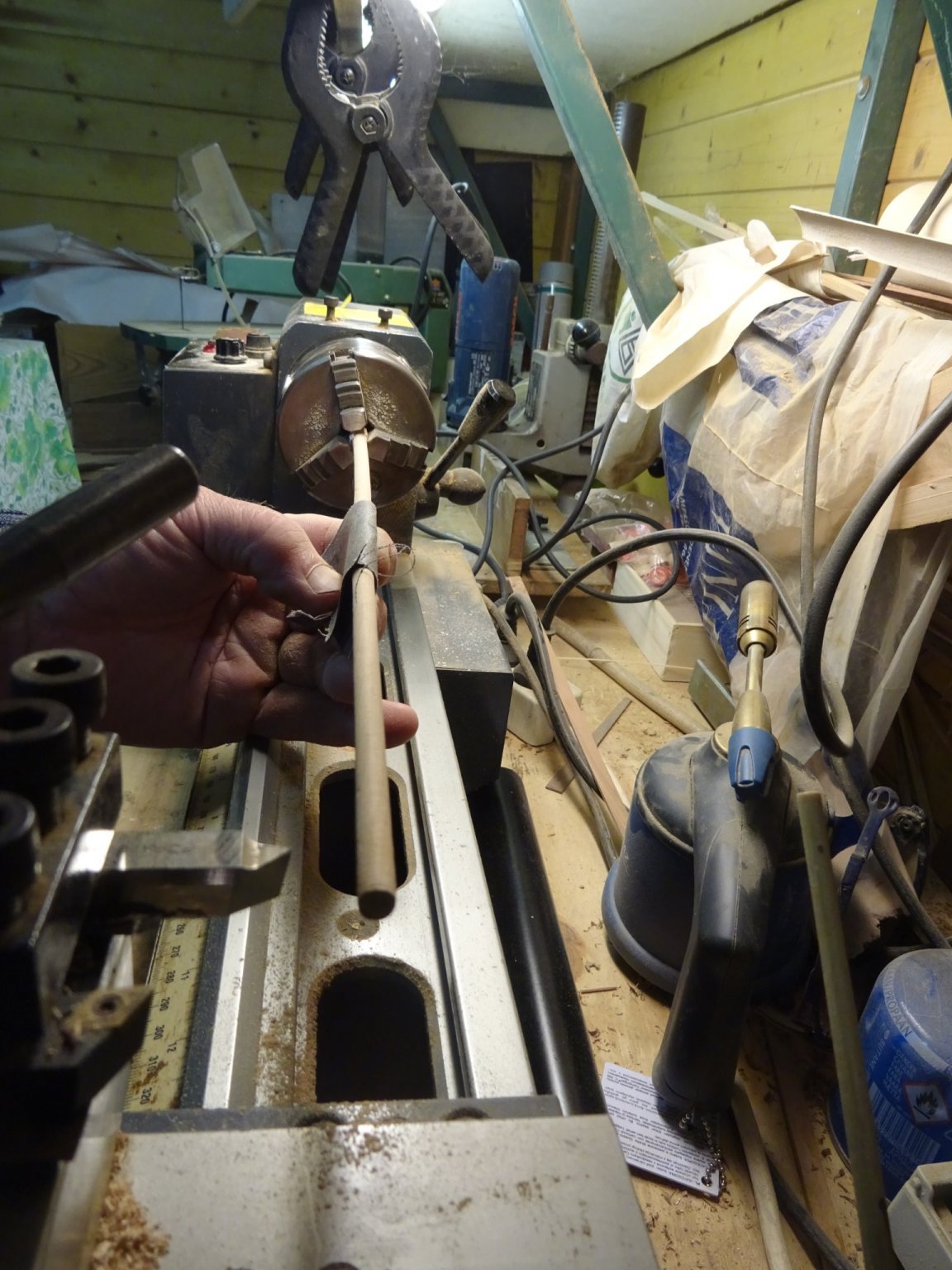
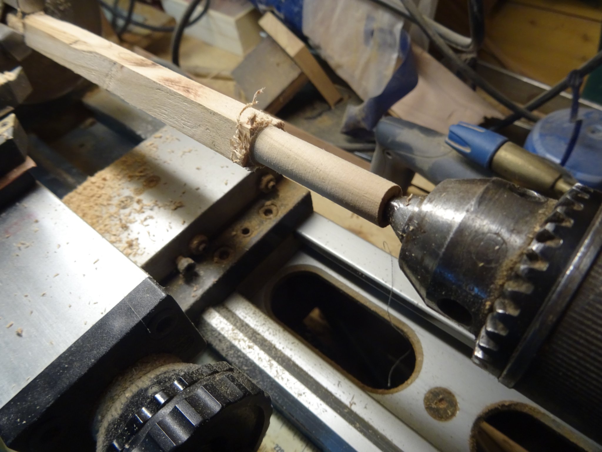
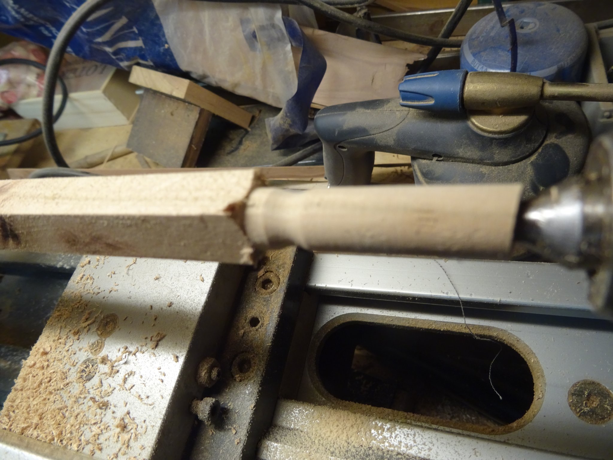
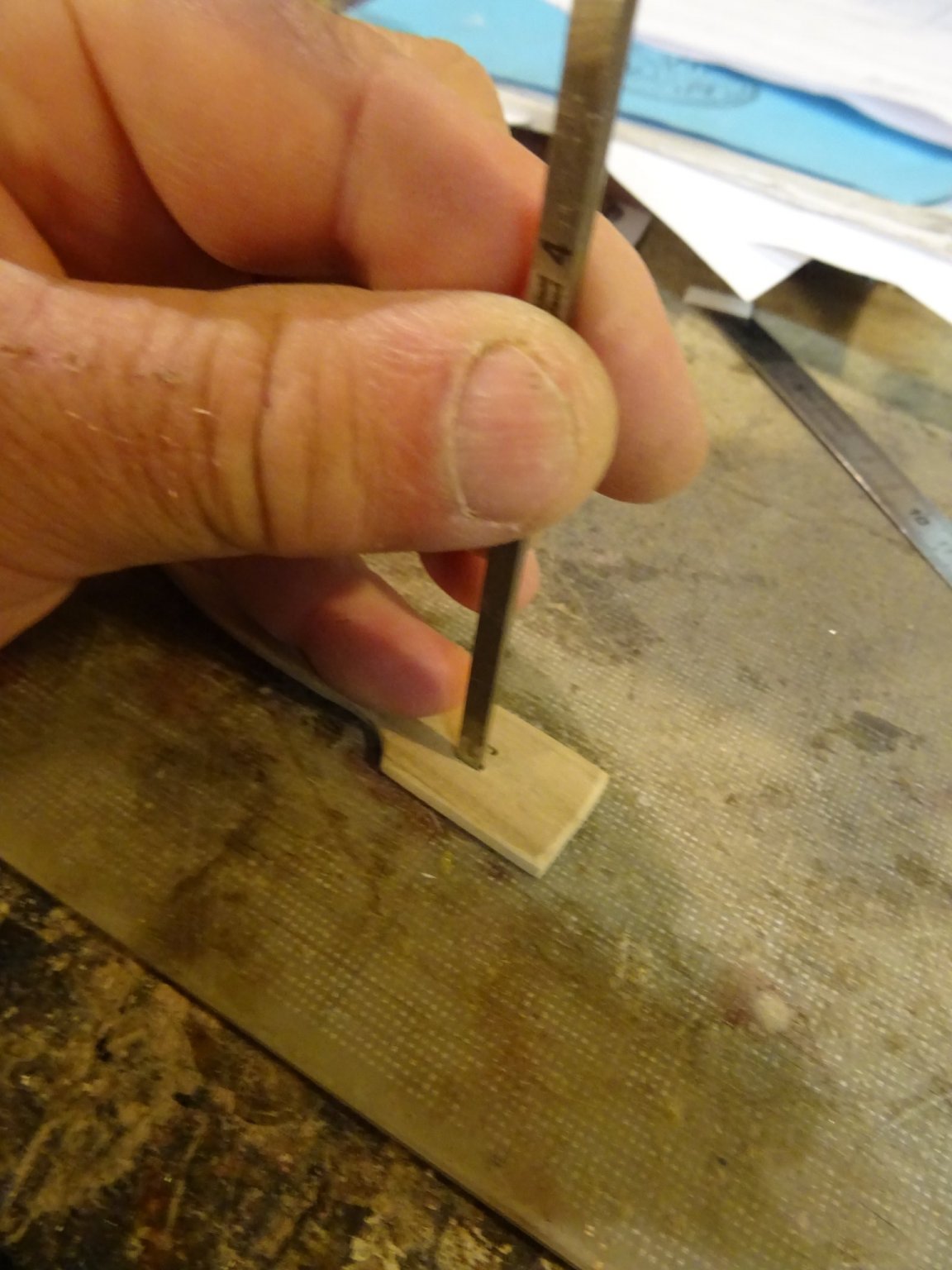
I make the shafts of the oars of pear sticks. I make them round to the correct diameter with the help of the drilling machine and tapping plates.

After tapping I place them in the lathe to sand them.

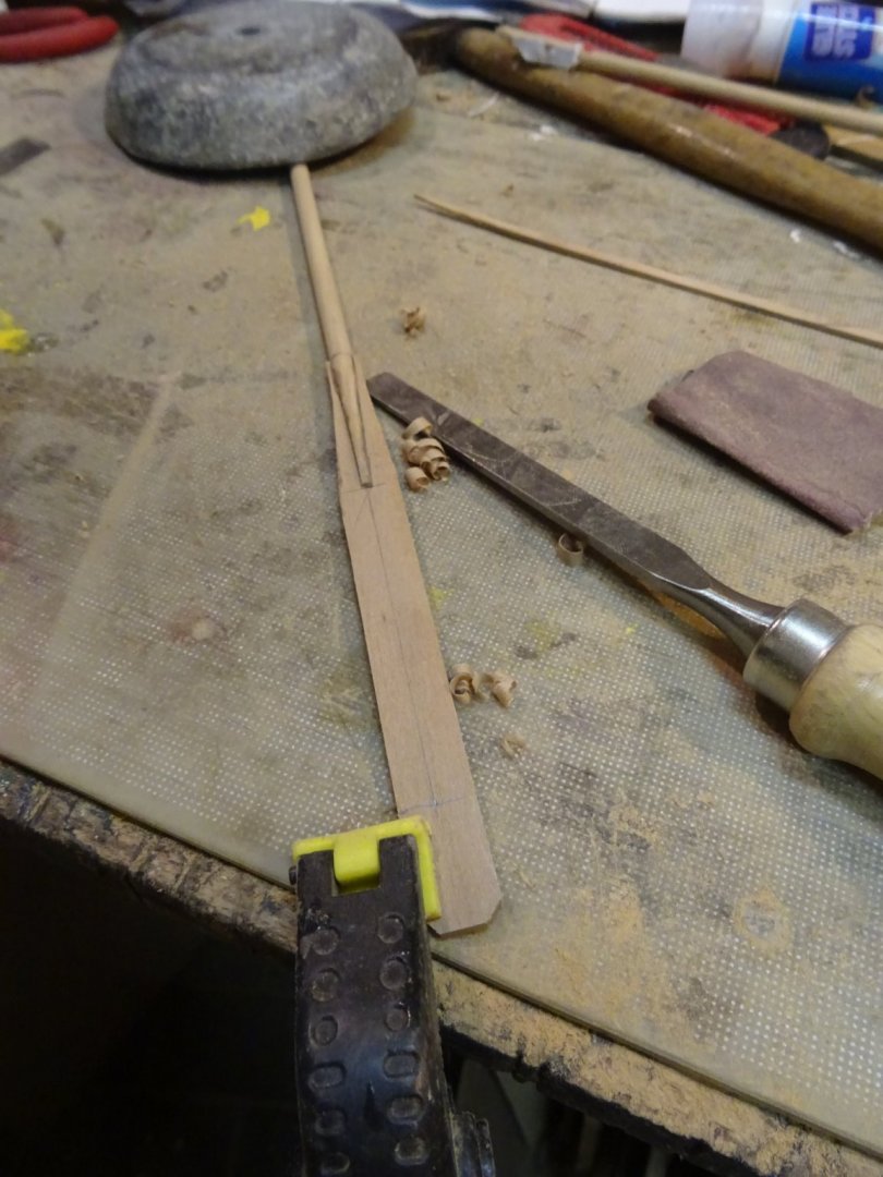
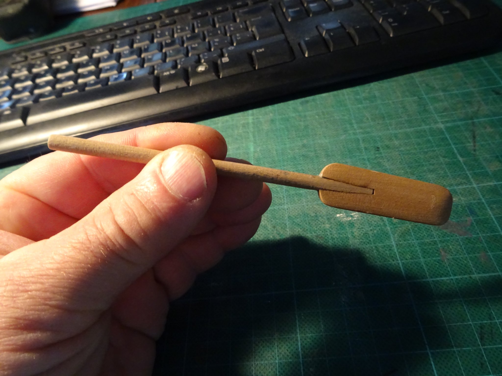
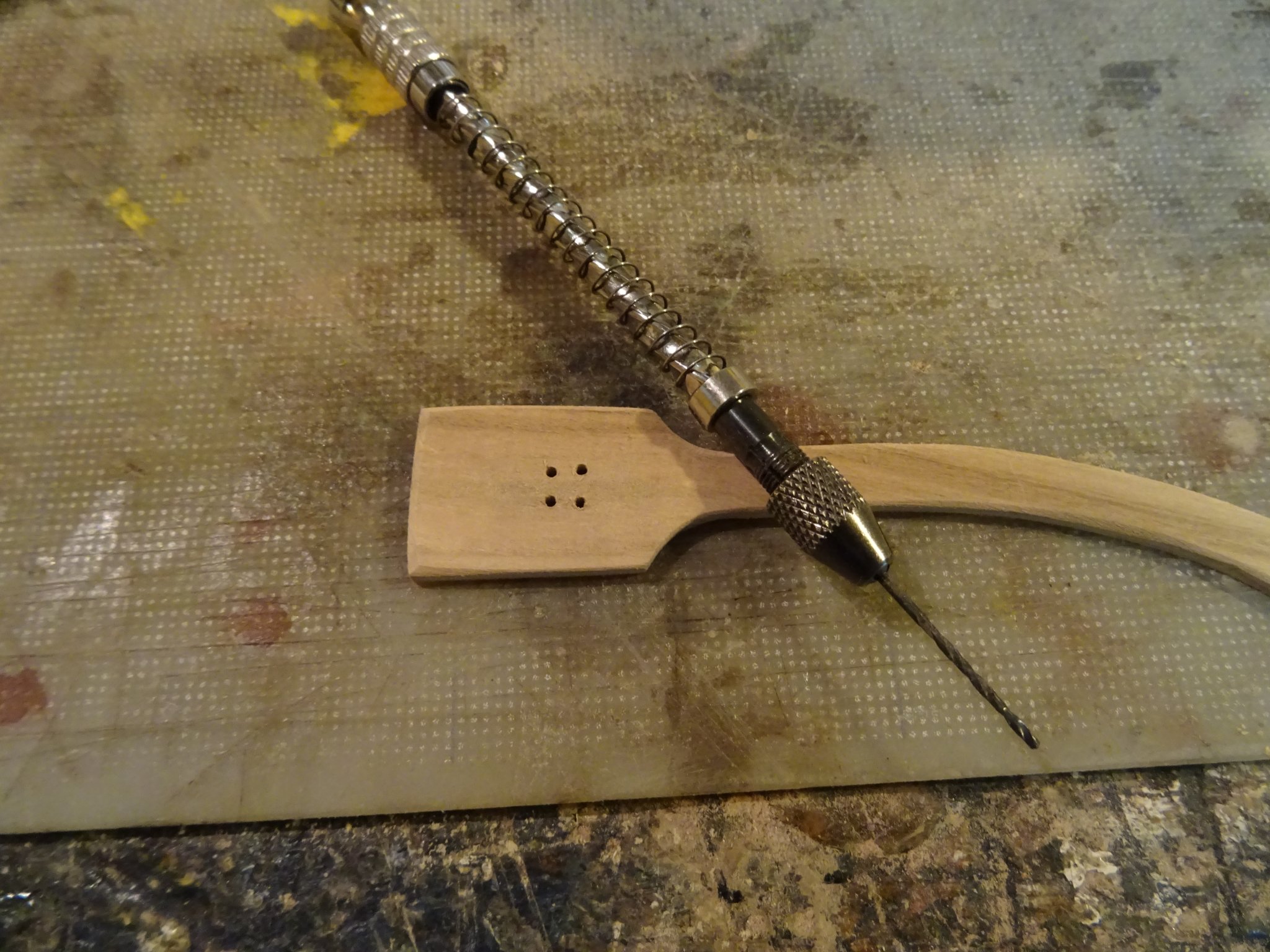
The blade is also made of pear and glued together with the shaft.
The shaping of the blade is done with the chisel and with sand paper.
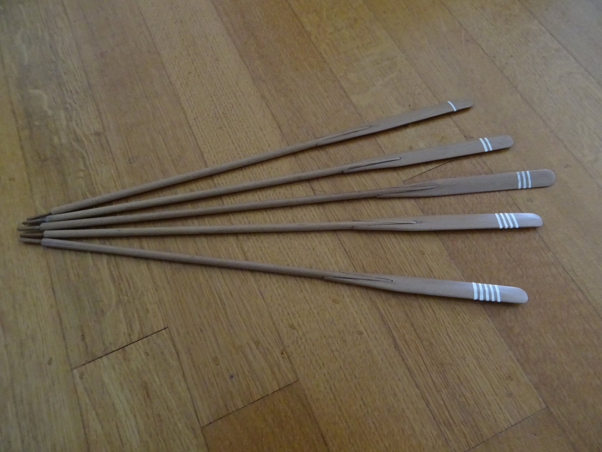
When the oars are shaped, I varnish them and tape them with masking tape to paint the position markings.
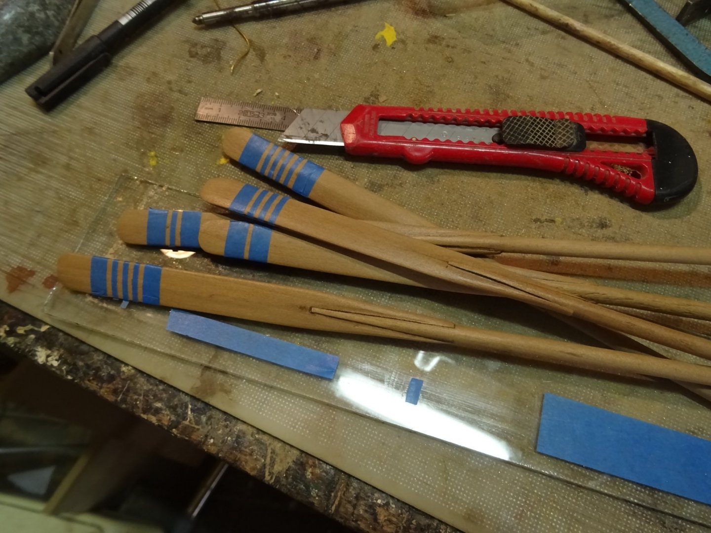
The five finished oars. They are marked from one to five, oar one is the forward oar and oar five the backward.

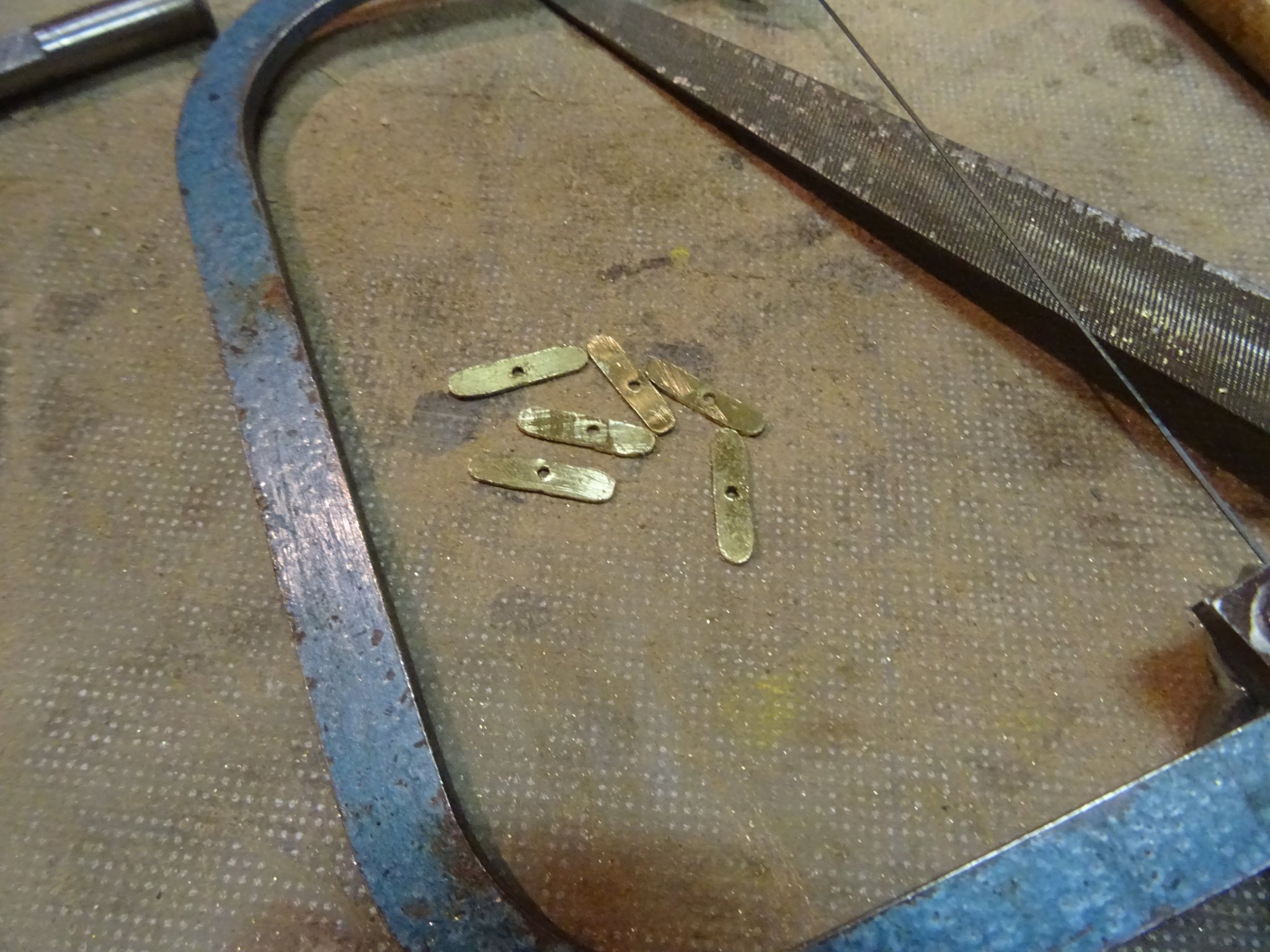
The oar locks are made of brass. I make the parts for six although I only need five because I have the experience that during the making there is always a piece falling on the ground that remains missing until it is not needed any more.

The pieces soldered together.
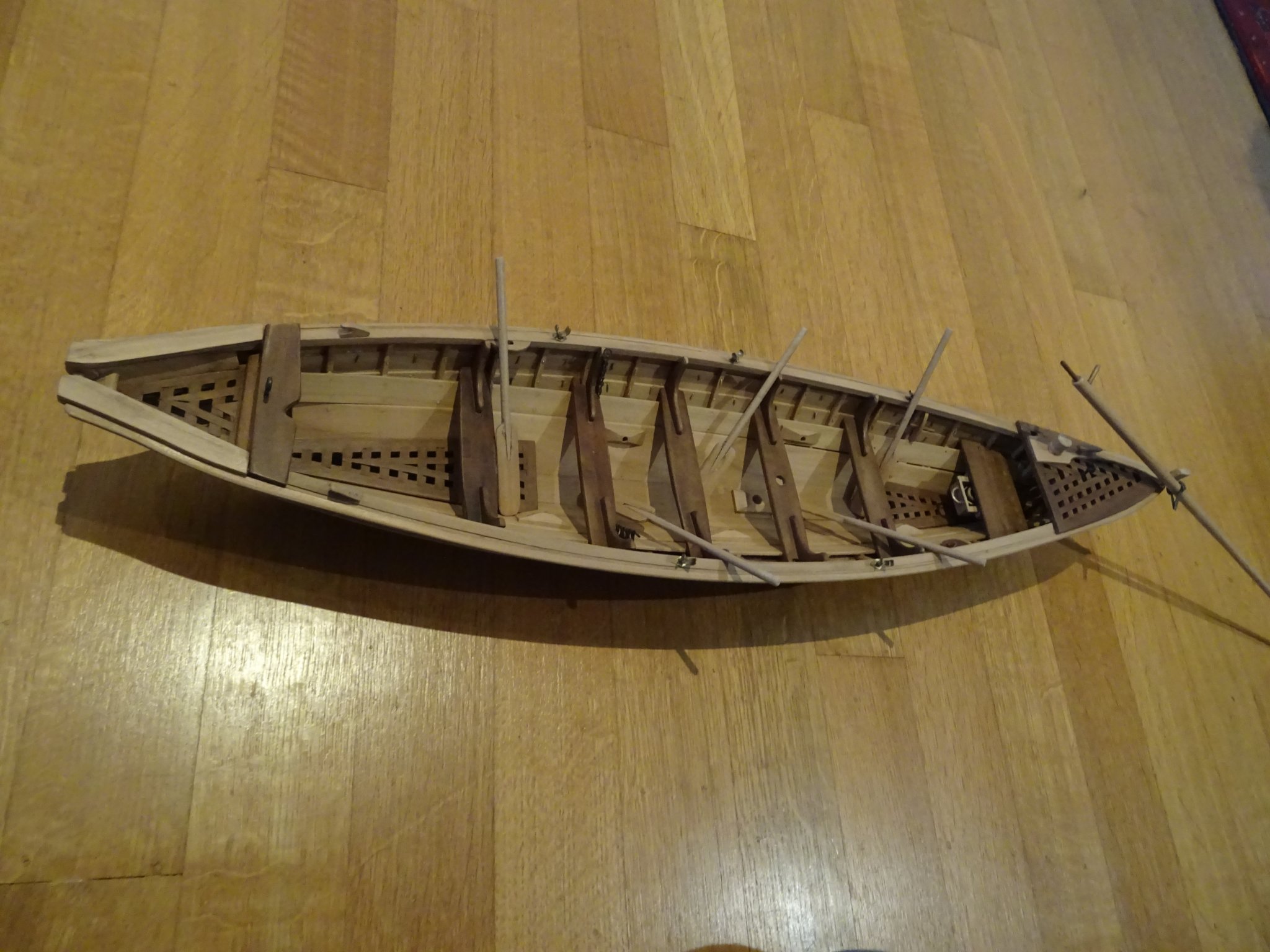
That is how they look on the boat

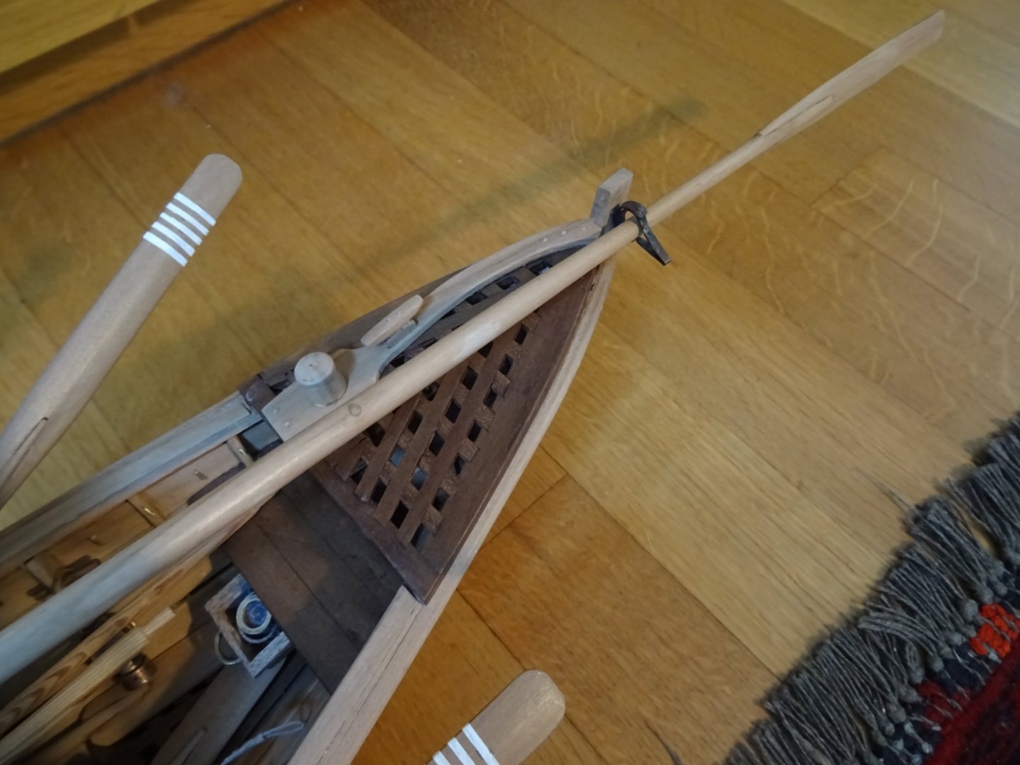
The boat is also steered with an oar. The making of it is the same as above, but here I have to take care that the blade goes through the steering oar lock.
The boat equipped with oars and steering oar.


-
-
This is gradually becoming a real metropolis.
-
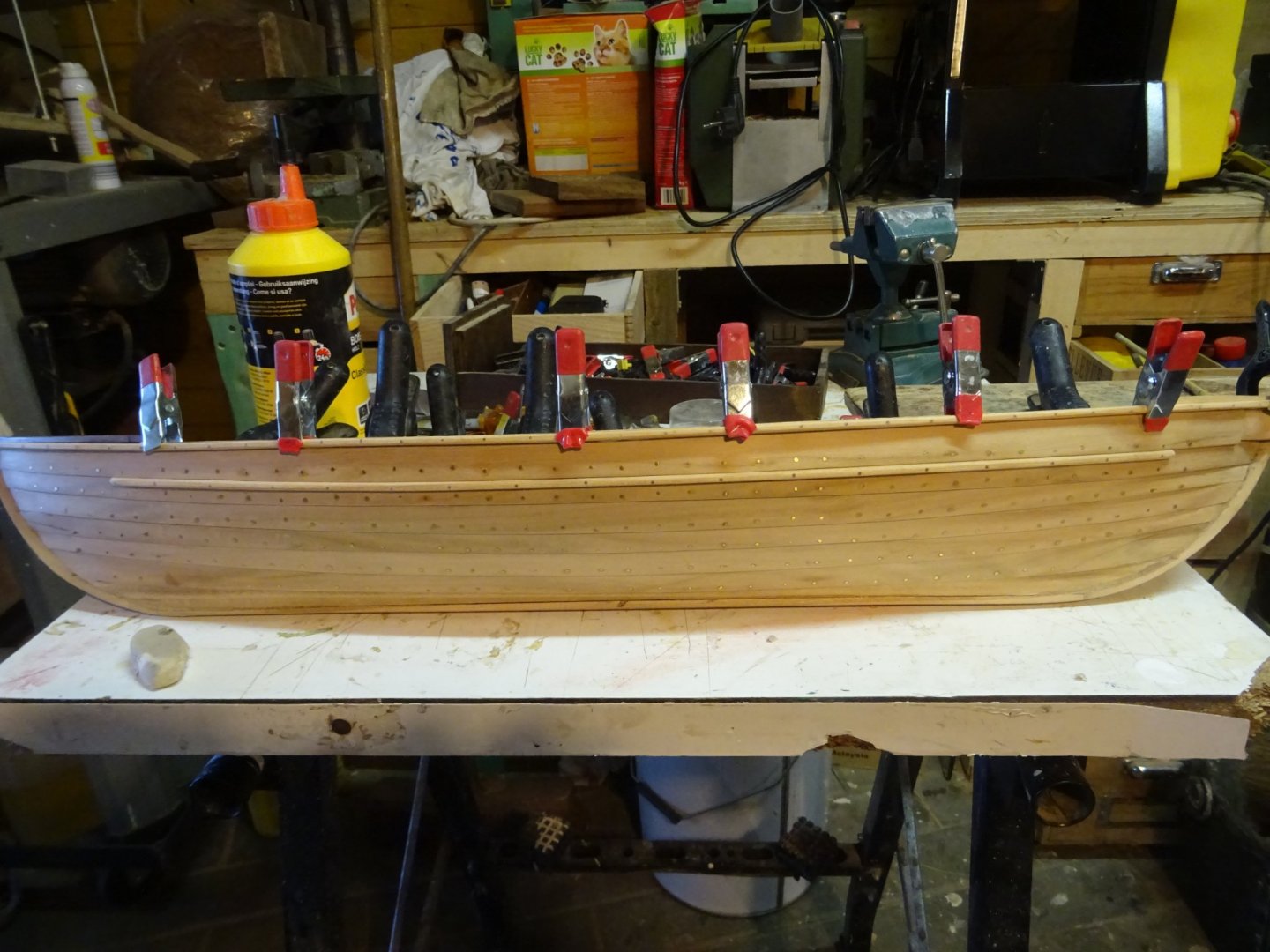
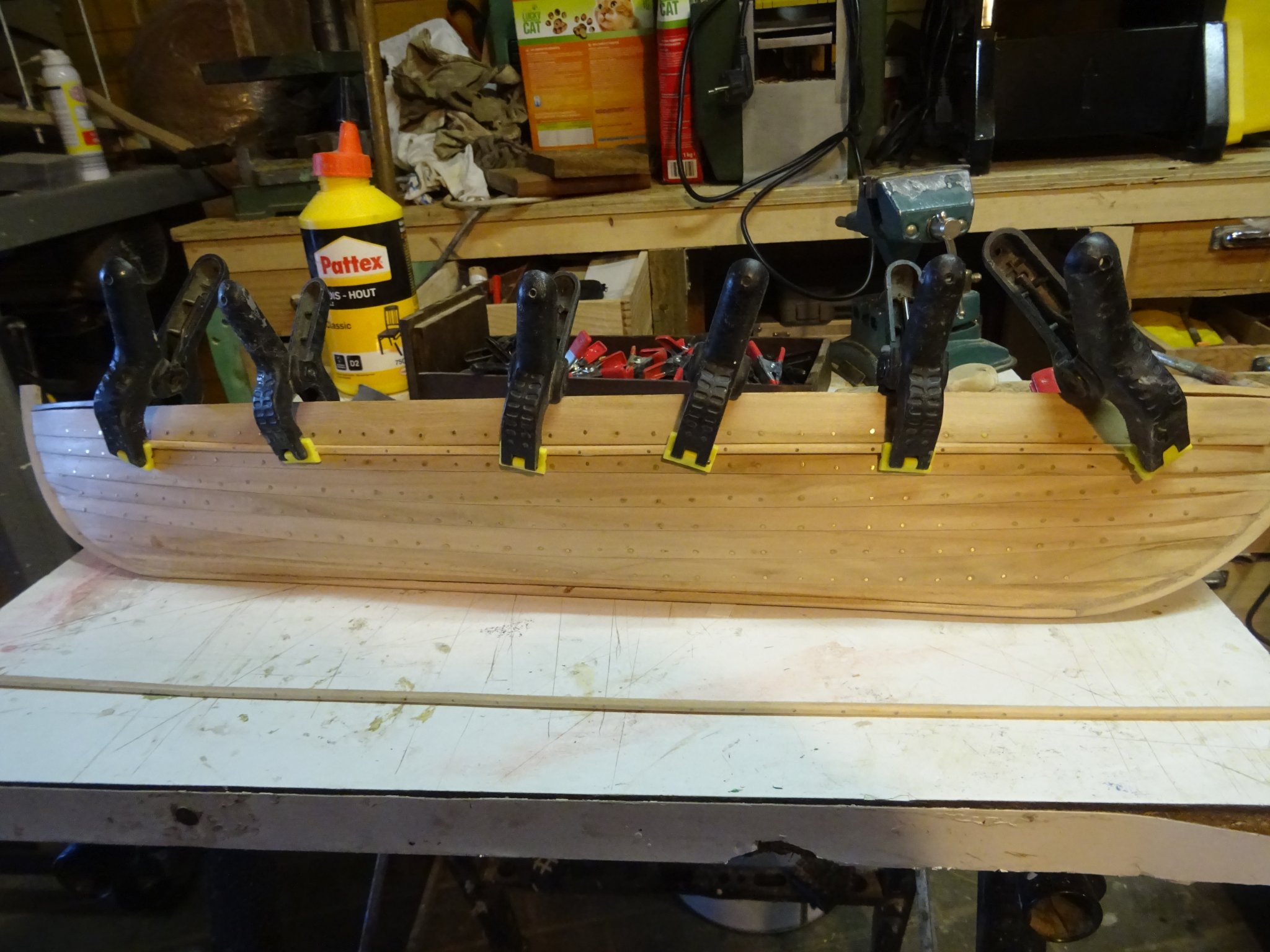
6. Finishing the outside of the hull
Gluing the rubbing piece.
Gluing the gunwale.
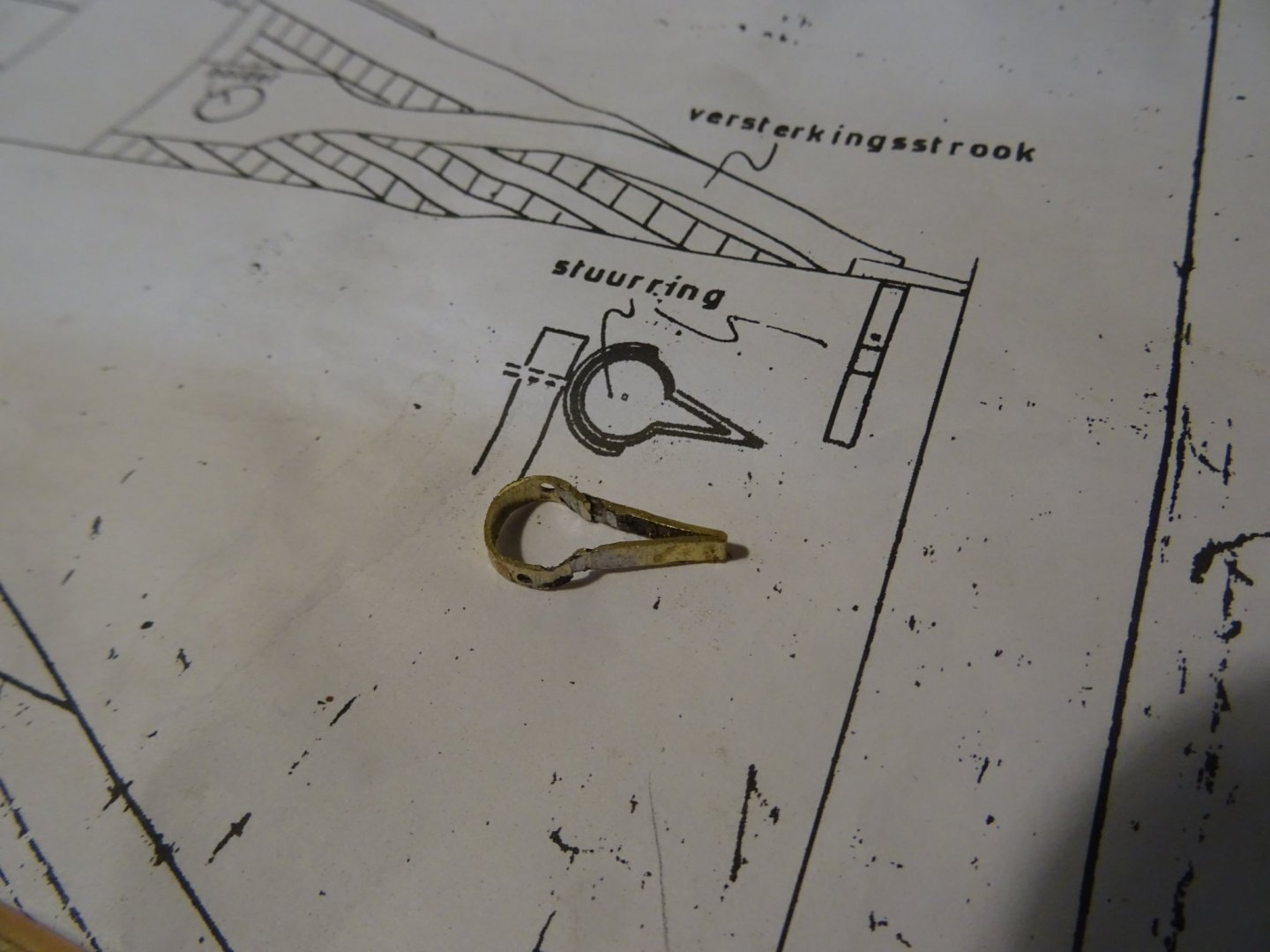
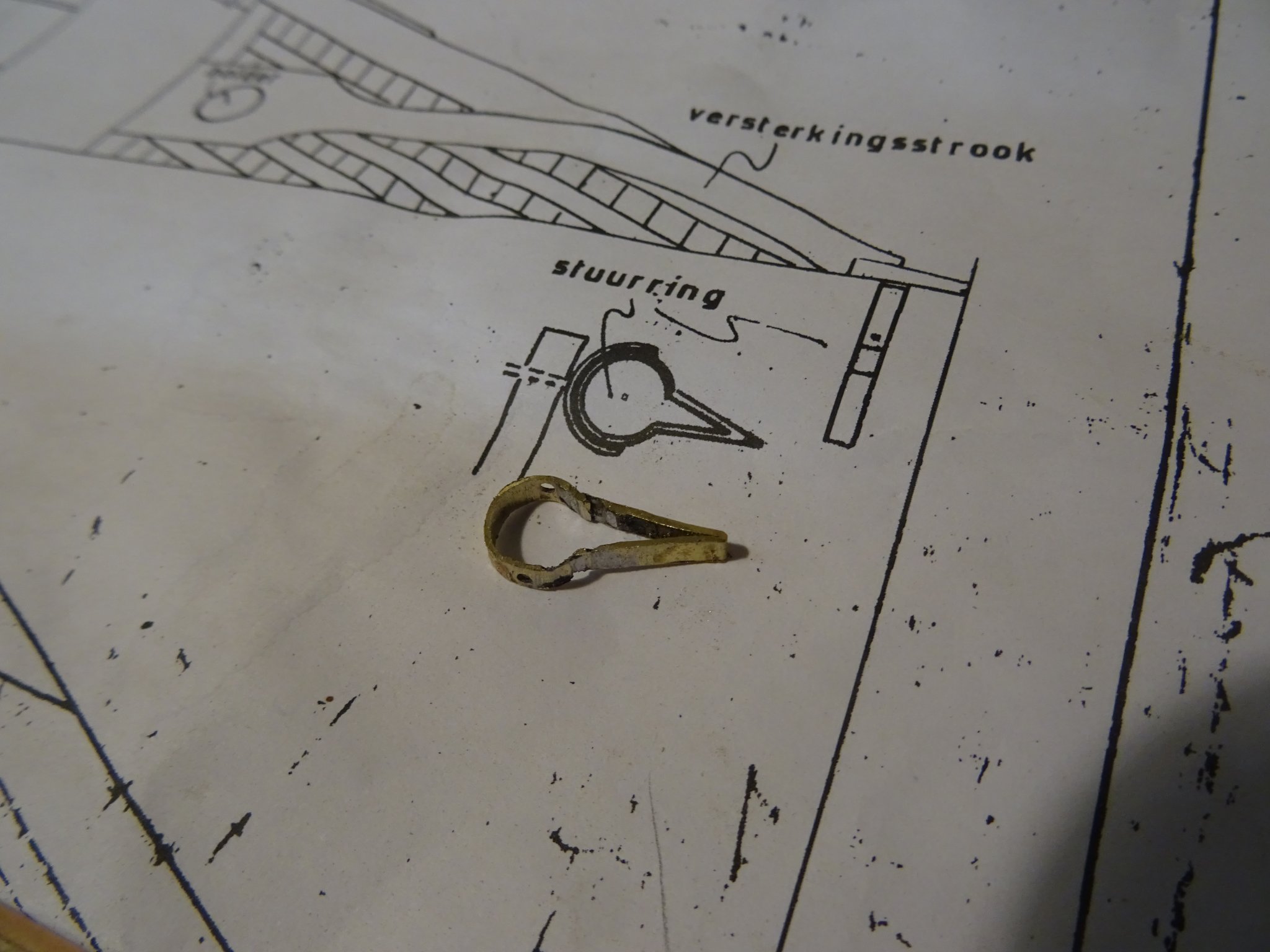
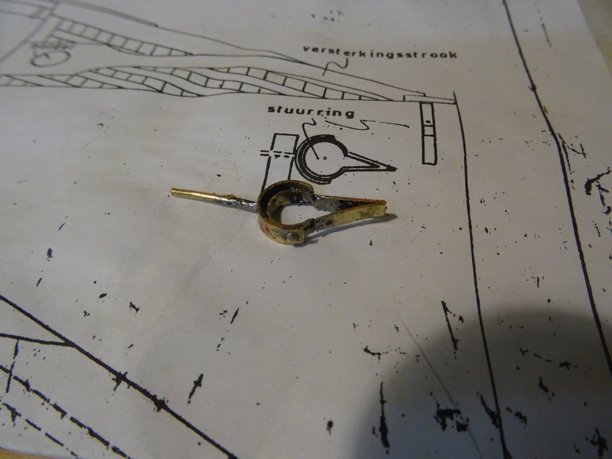
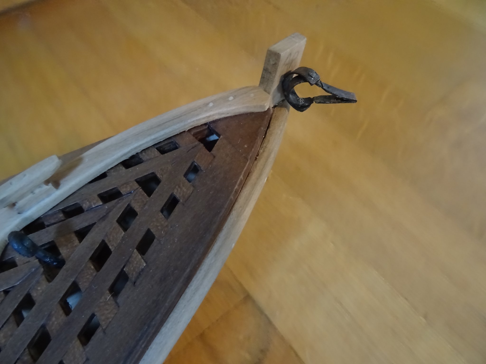
The steering oar fits in a metal oarlock which can hinge.
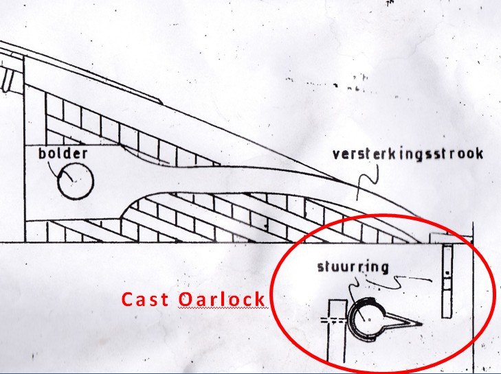
Making the oarlock for the steering oar.
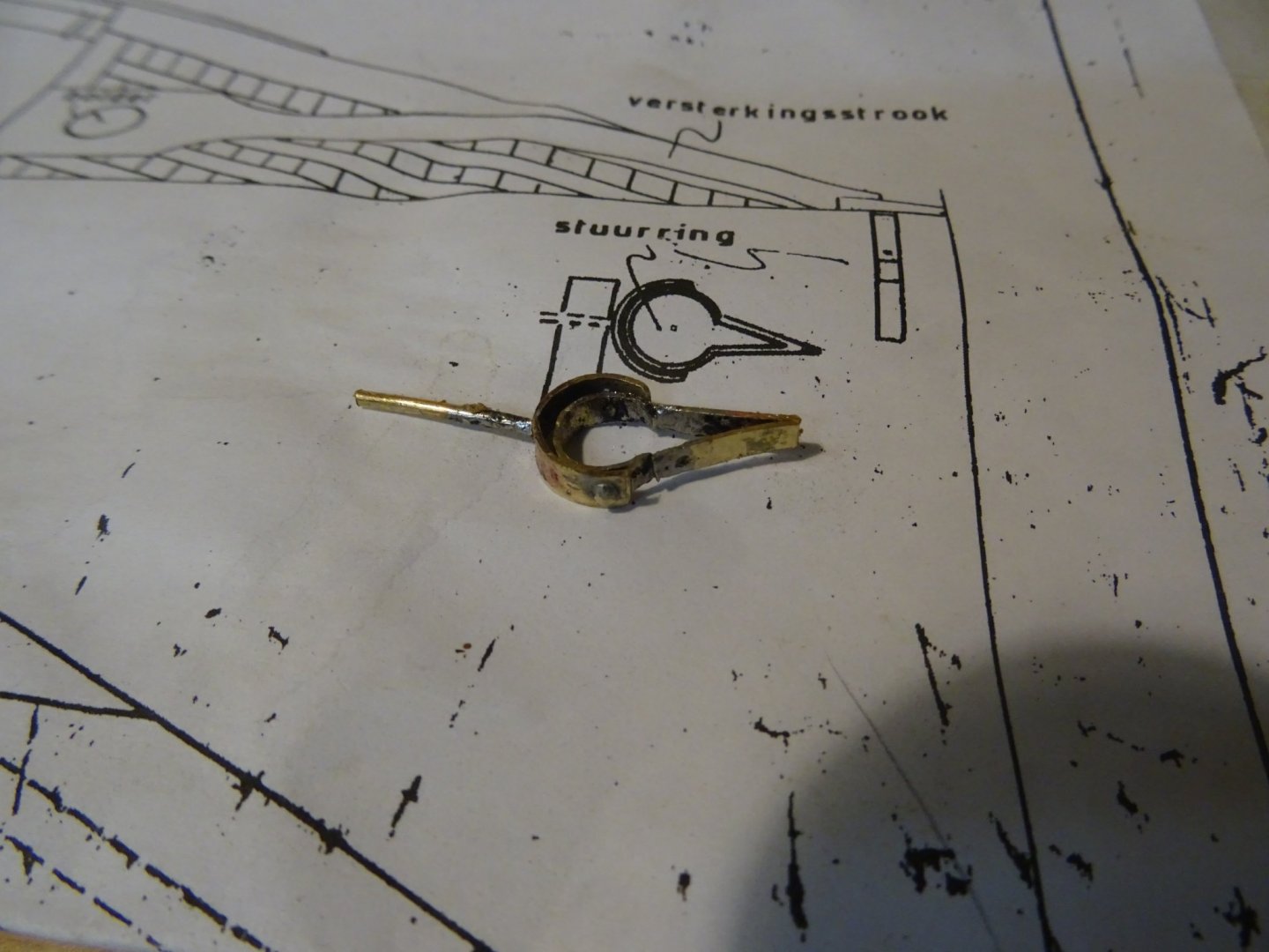
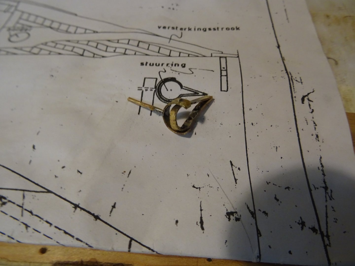
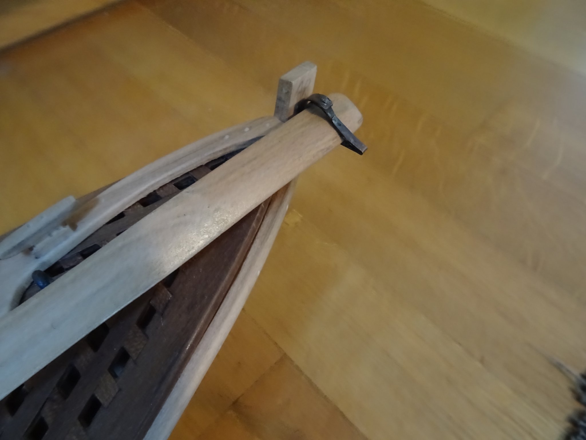
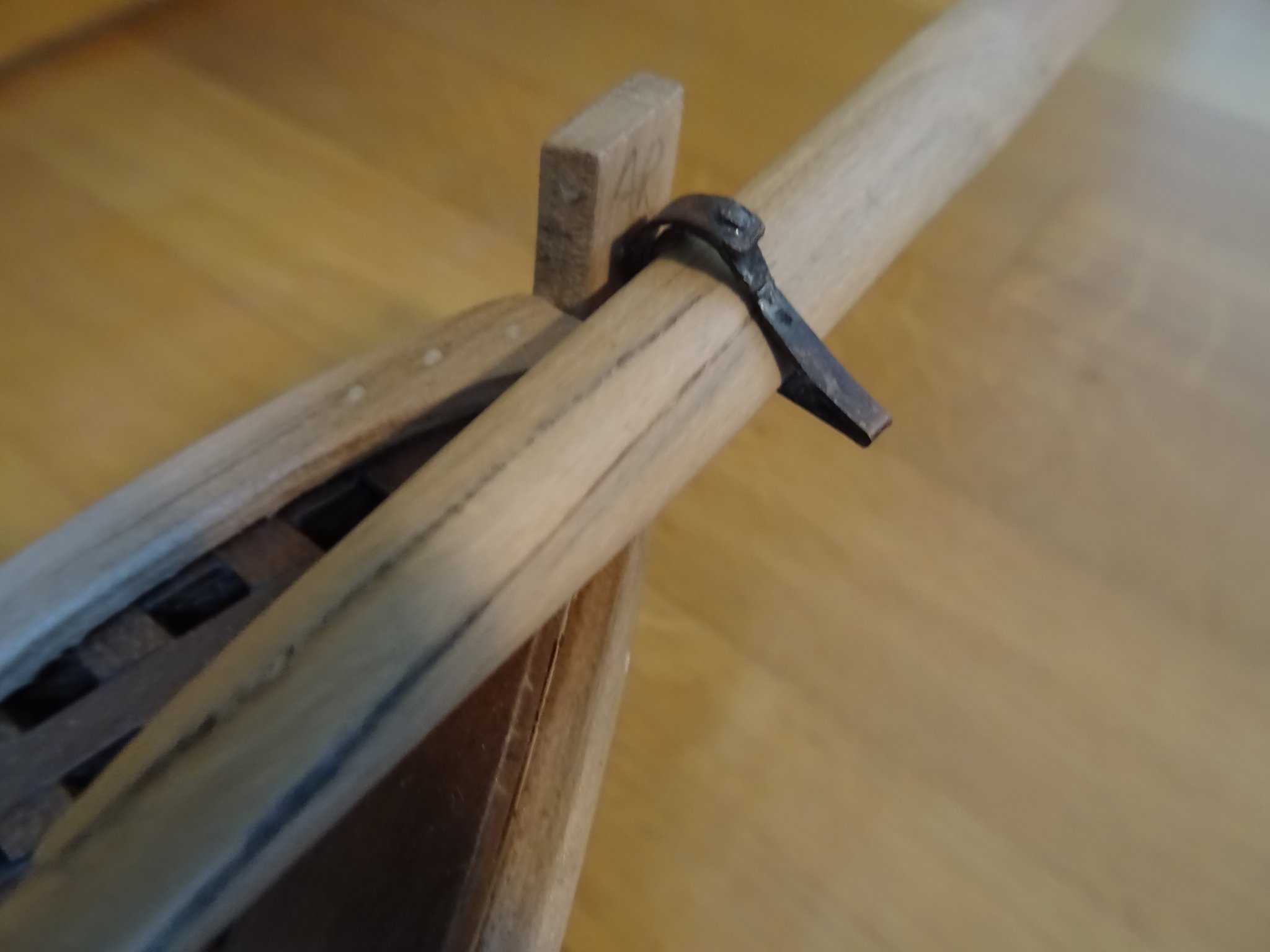
The oarlock is blackened and placed into its position at the stern.
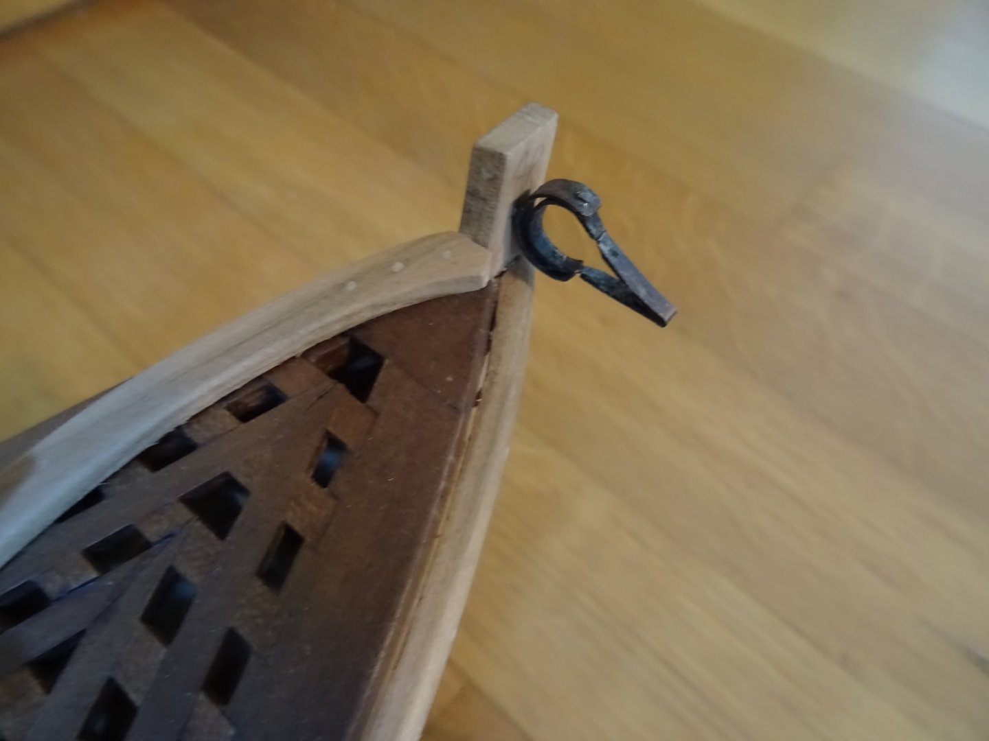

The oarlock has an angular protrusion to give space for the oar blade to slide through it.
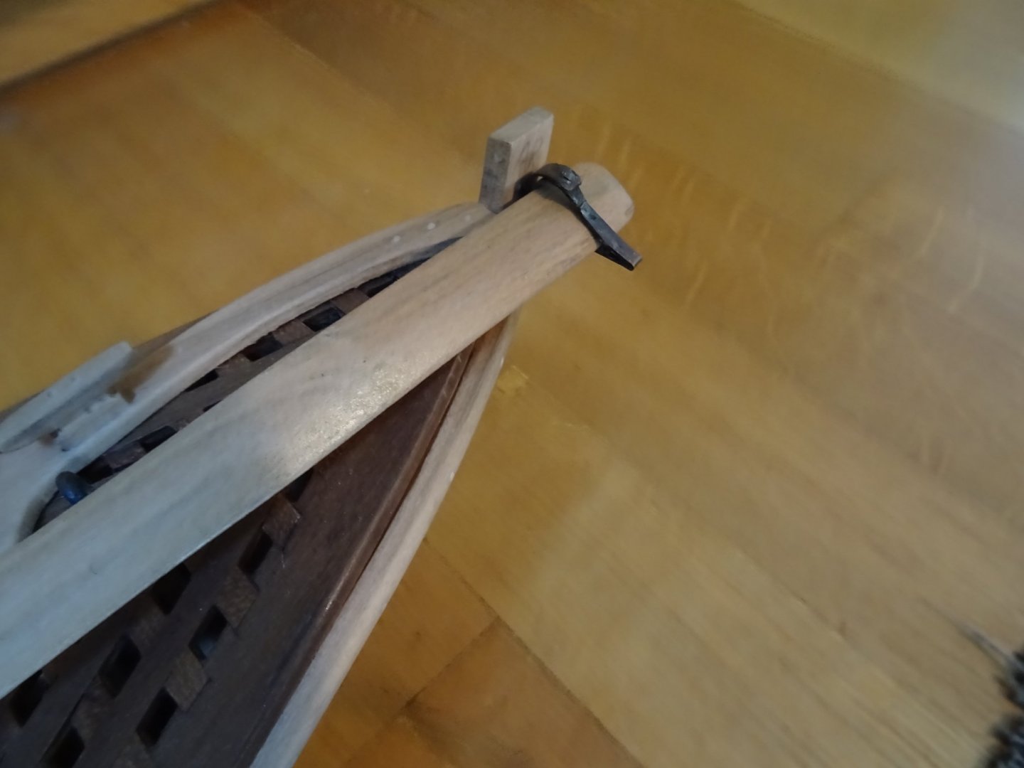

Here you see the model in a further stage of finishing with the steering oar in place.
Thank you very much for reading this log and for your likes.
Till next week!
- mtaylor, GrandpaPhil, bruce d and 3 others
-
6
-
Ab, your son is a real artist. It is just like a 17th century Jan Abrahamsz Beerstraten painting.
- mtaylor and flying_dutchman2
-
2
-
-
-
Gary,
I fully agree with all previous comments. Your model and the display are fantastic. Your log was extremely engaging and educational to read.
Congratulations!
- FriedClams, druxey, BobG and 1 other
-
4
-
4. Continuing the interior of the hull.
Placing the rising for the forward floor grating.

The forward floor grating into place
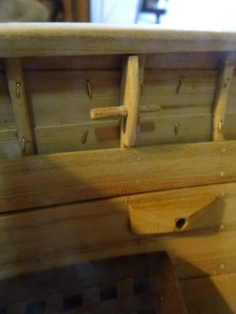
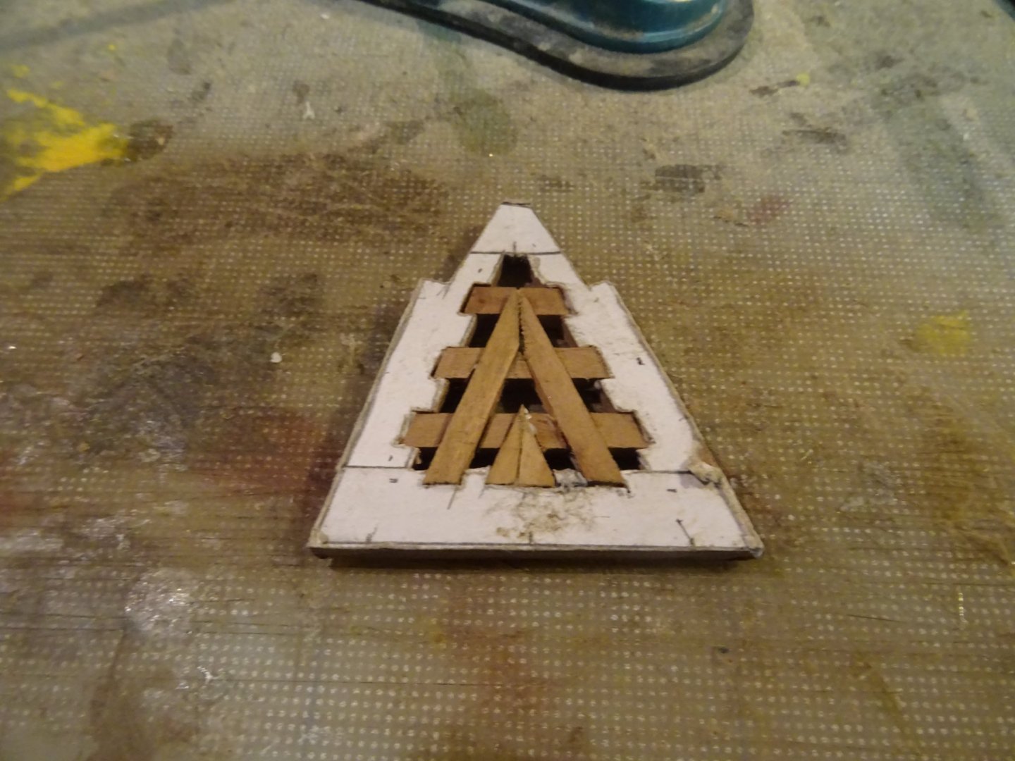
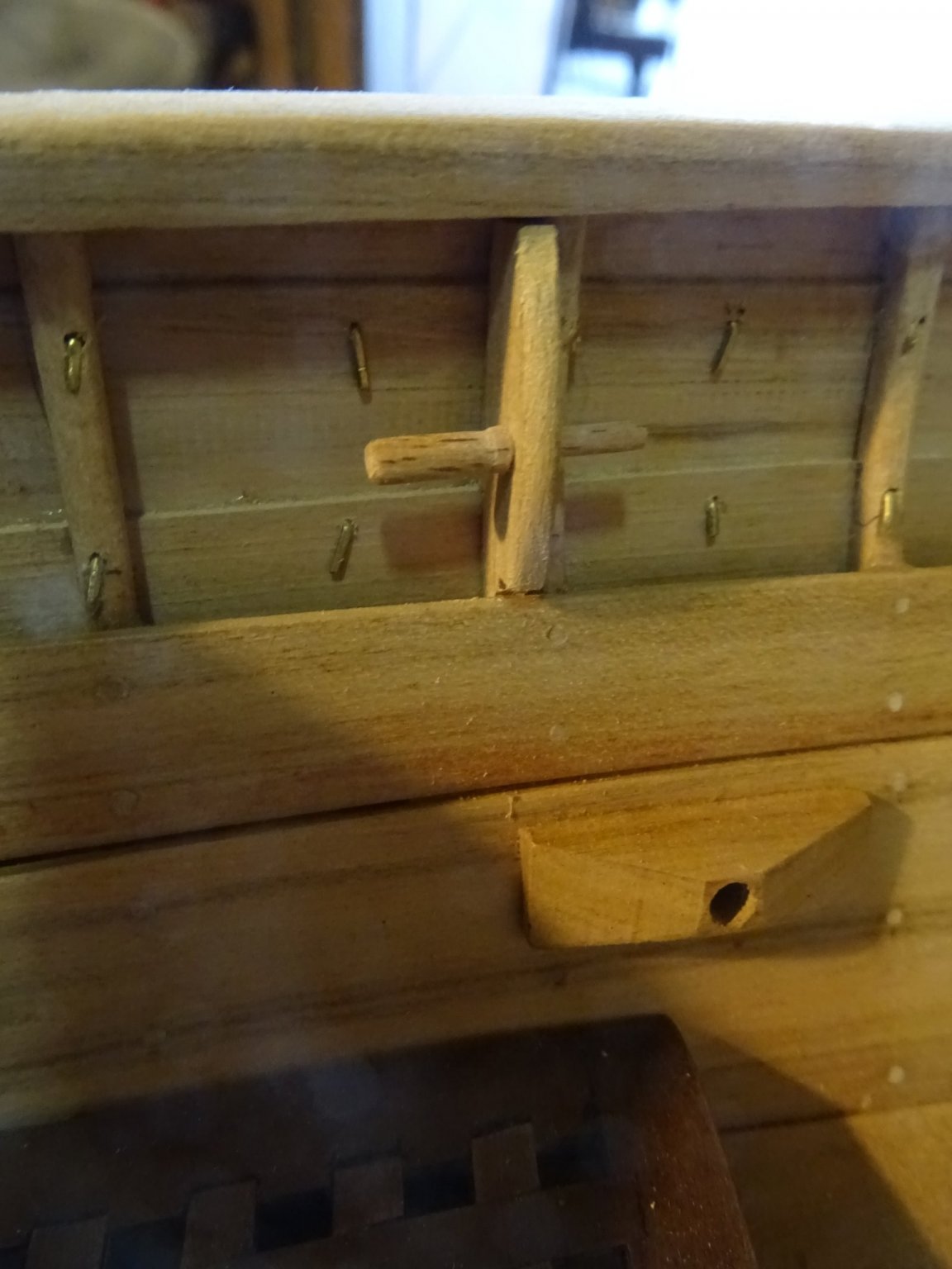
In the front of the boat is a high placed thwart. In that thwart is a recess in which the harpooner can place one leg to find support in the shaking boat while throwing his harpoon.
Fitting it.
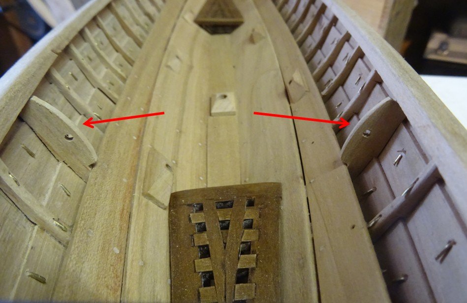
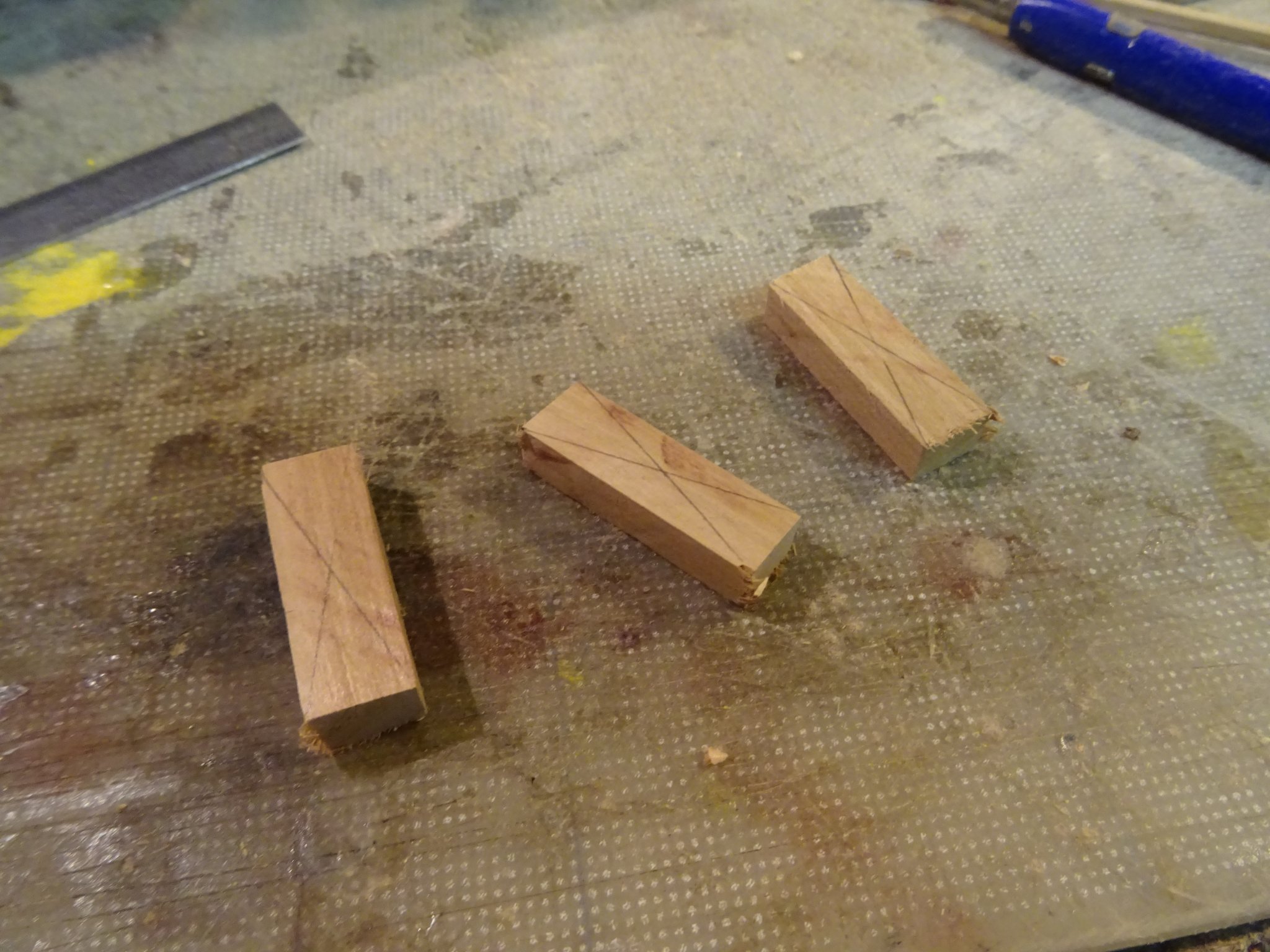
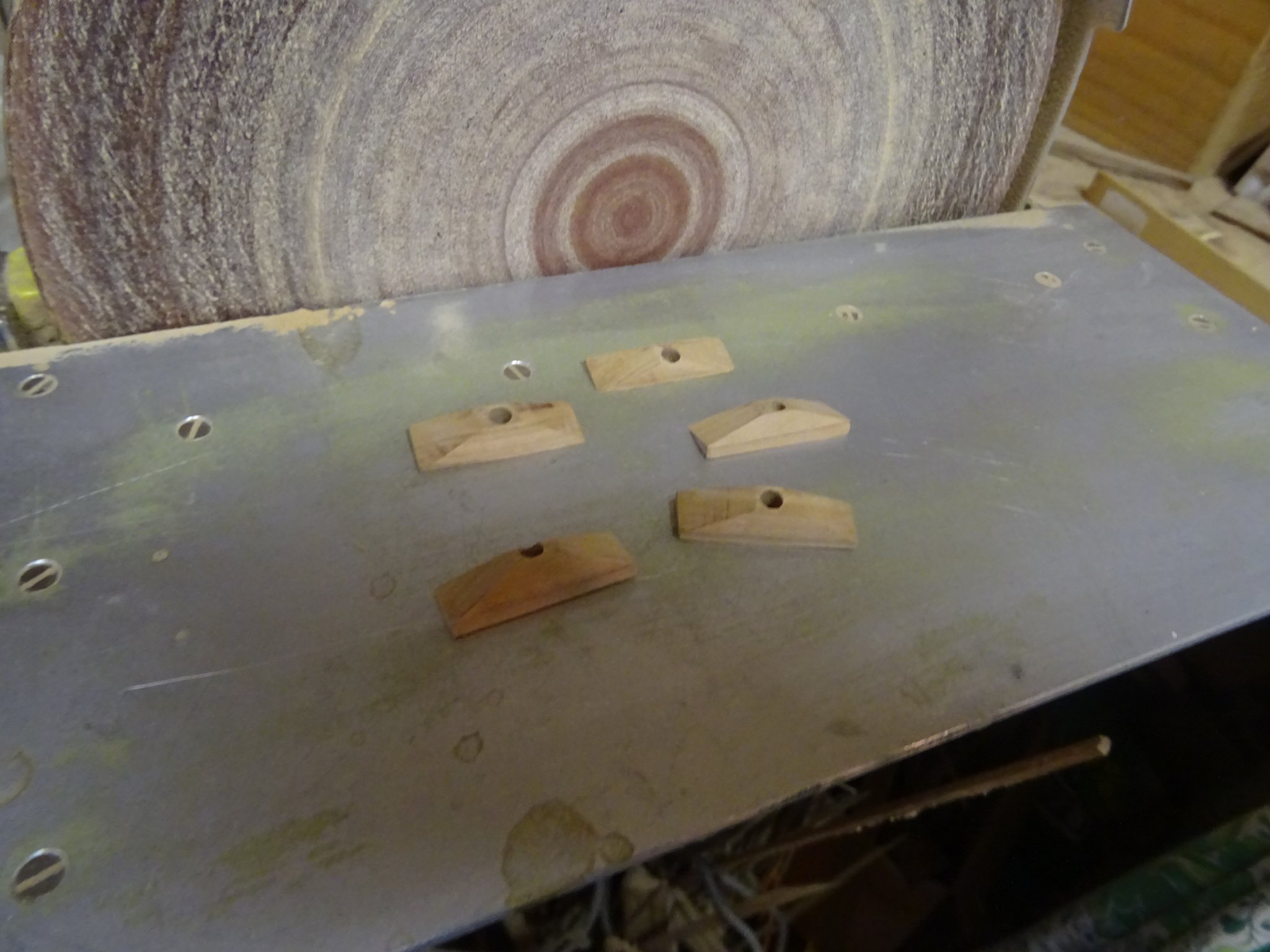
At the side of each rowers' position, opposite to the rowlock is a peak cleat in which can be placed the handle of the oar to hold it out of the water.
Shaping the peak cleats.


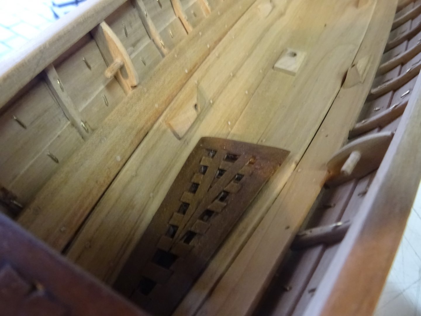
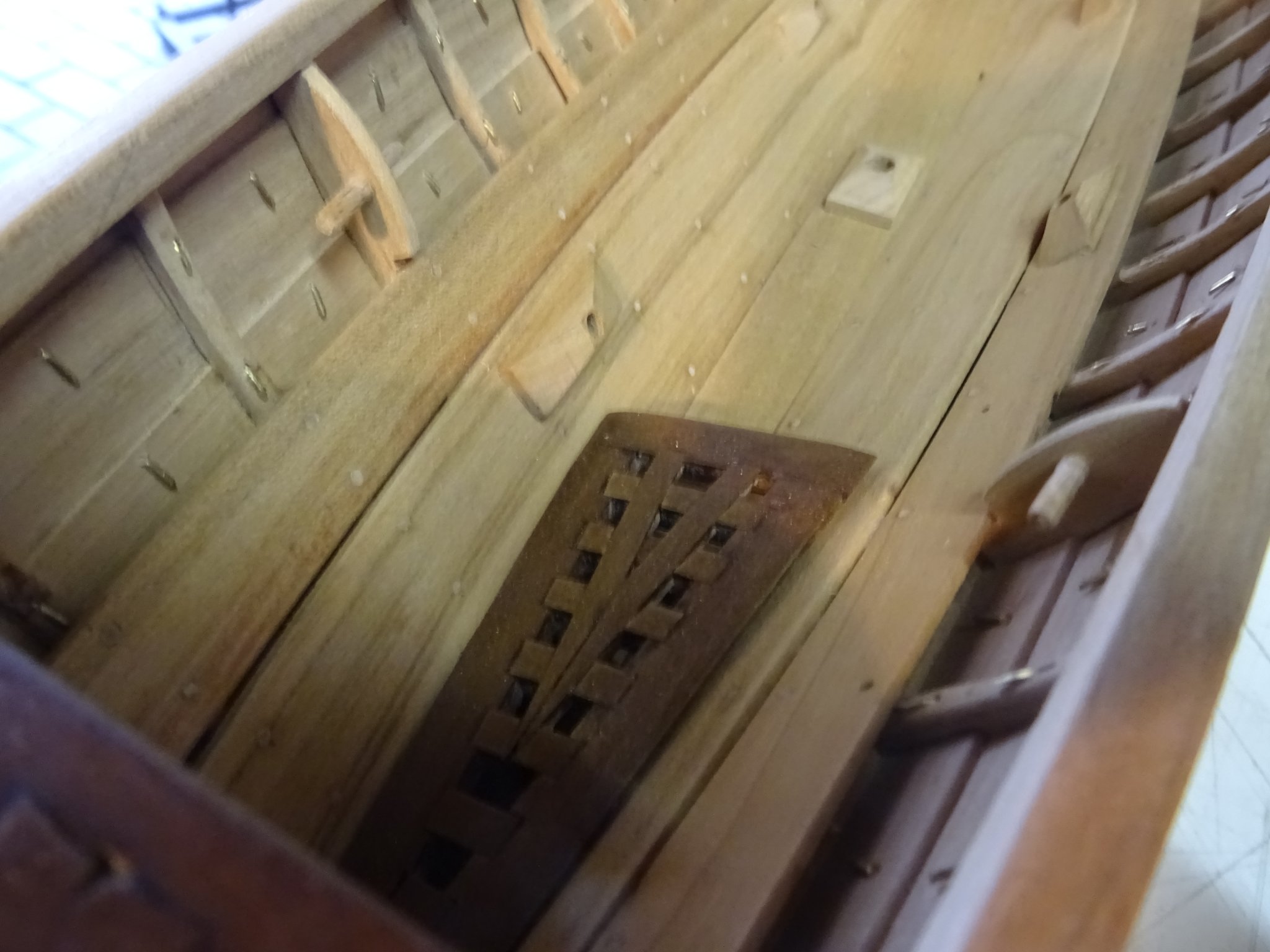
Here the peak cleats are glued into their positions. The gratings are already dark stained and the after deck pieces are glued.
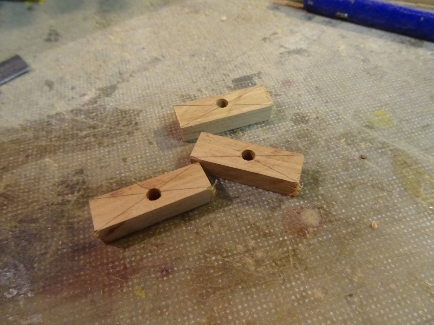
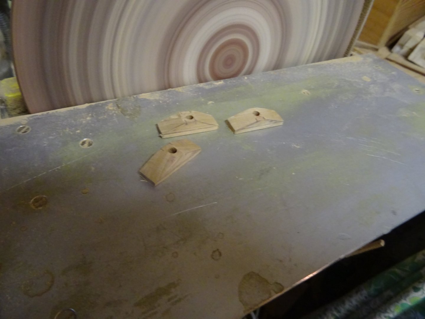
In the after section of the boat is on both sides a pin to belay the sheet when sailing.
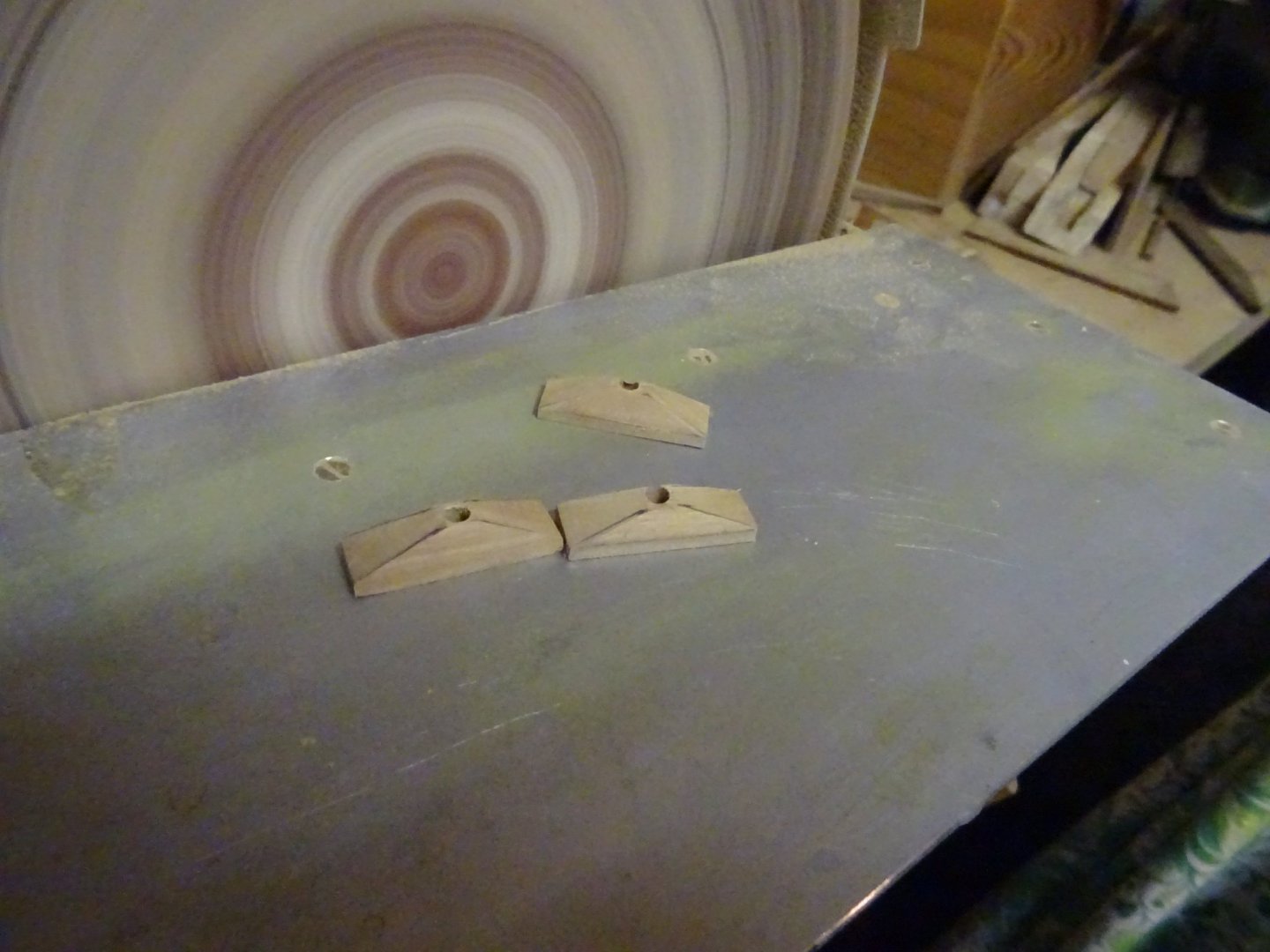
Determining the shape of the pin holders.


Pin holders placed.
Making the pins.
Pins in the holders.
Now it is time to make the thwarts. I start with the helmsman thwart which is a wide thwart.
In the heat of the action, I forgot to make pictures of the making of the thwarts.
I have to pass immediately to the knees.
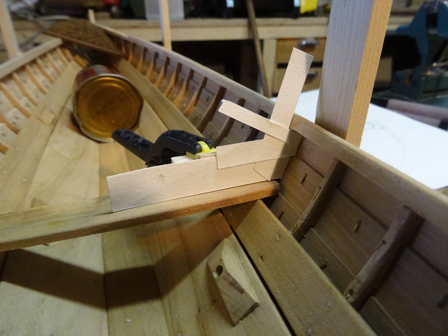
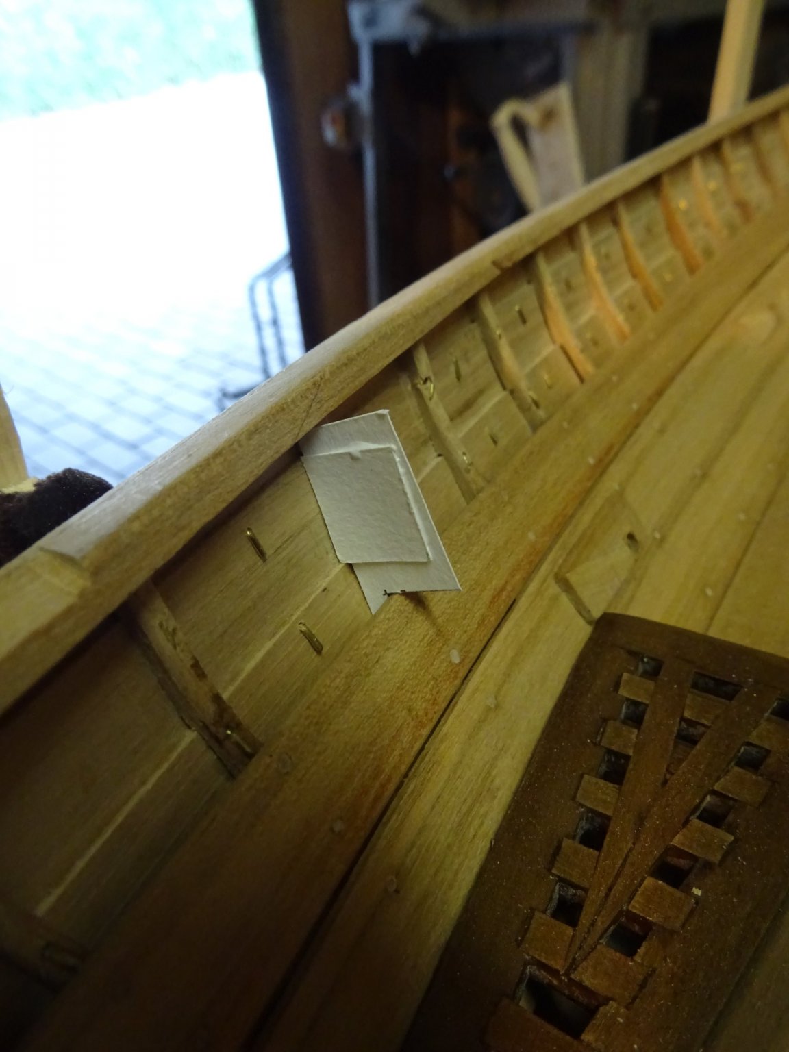
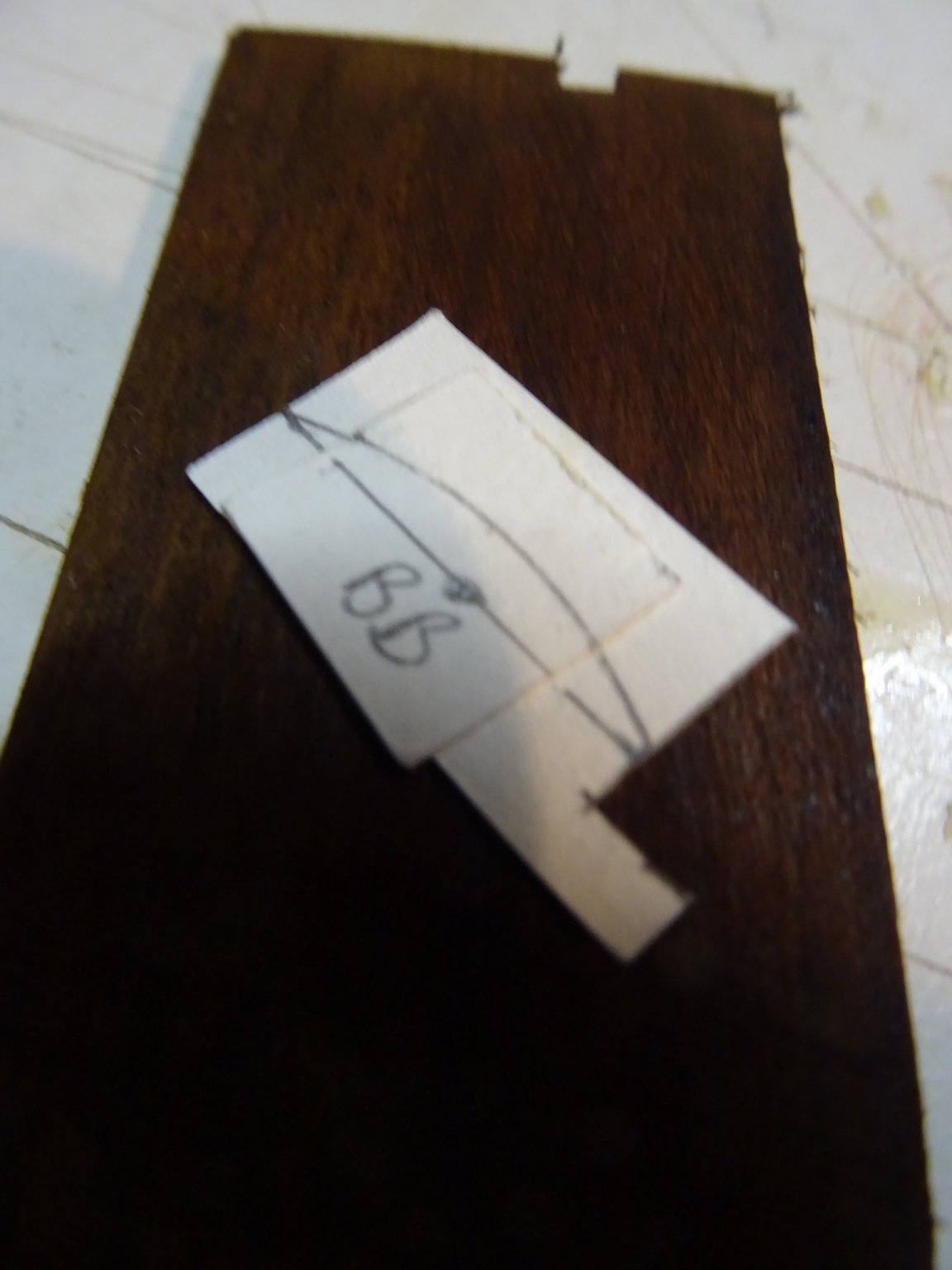
To determine the shape of the knees, I use the proven method with the paper strips to make templates.

Rounding the upper sides of the knees.
All the thwarts an knees installed.

With the mast thwart placed, I can make the mast step and locate its exact position.
The mast step.
Two lifting eyes have to be placed to hook the boat into the davit.
The eyes were already made some time ago of 2mm Ø brass rods.
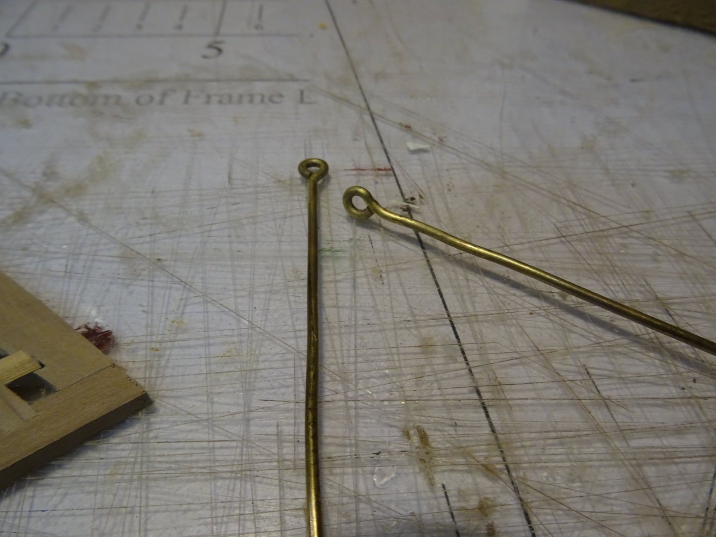
Now they can be placed definitively.

Thank you very much for reading this log and for your likes.
Till next week!
- Siggi52, GrandpaPhil, Blackreed and 3 others
-
6
-
-
-
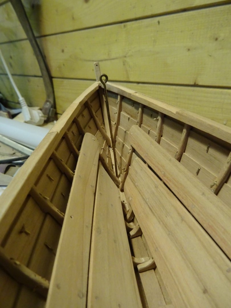
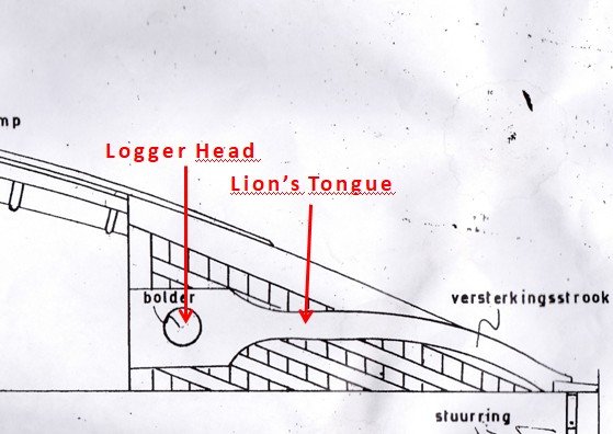
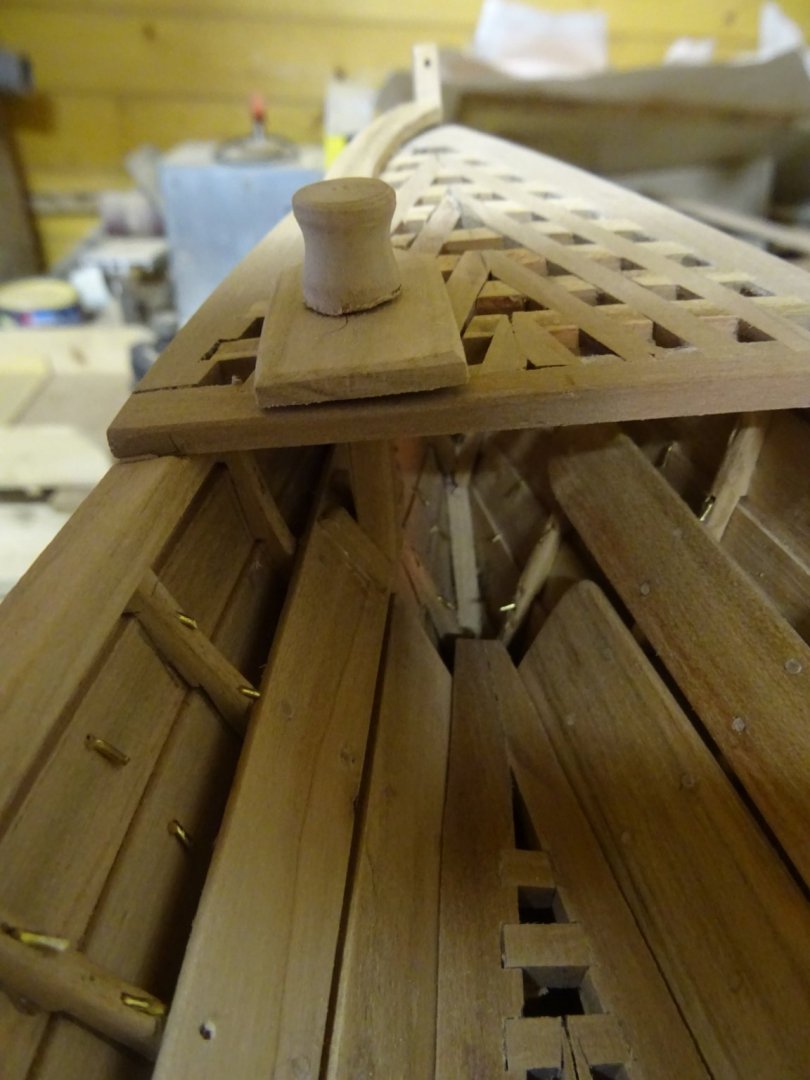
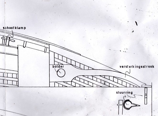
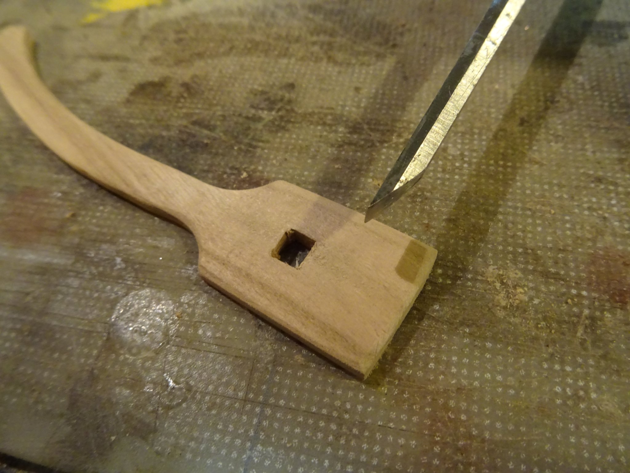
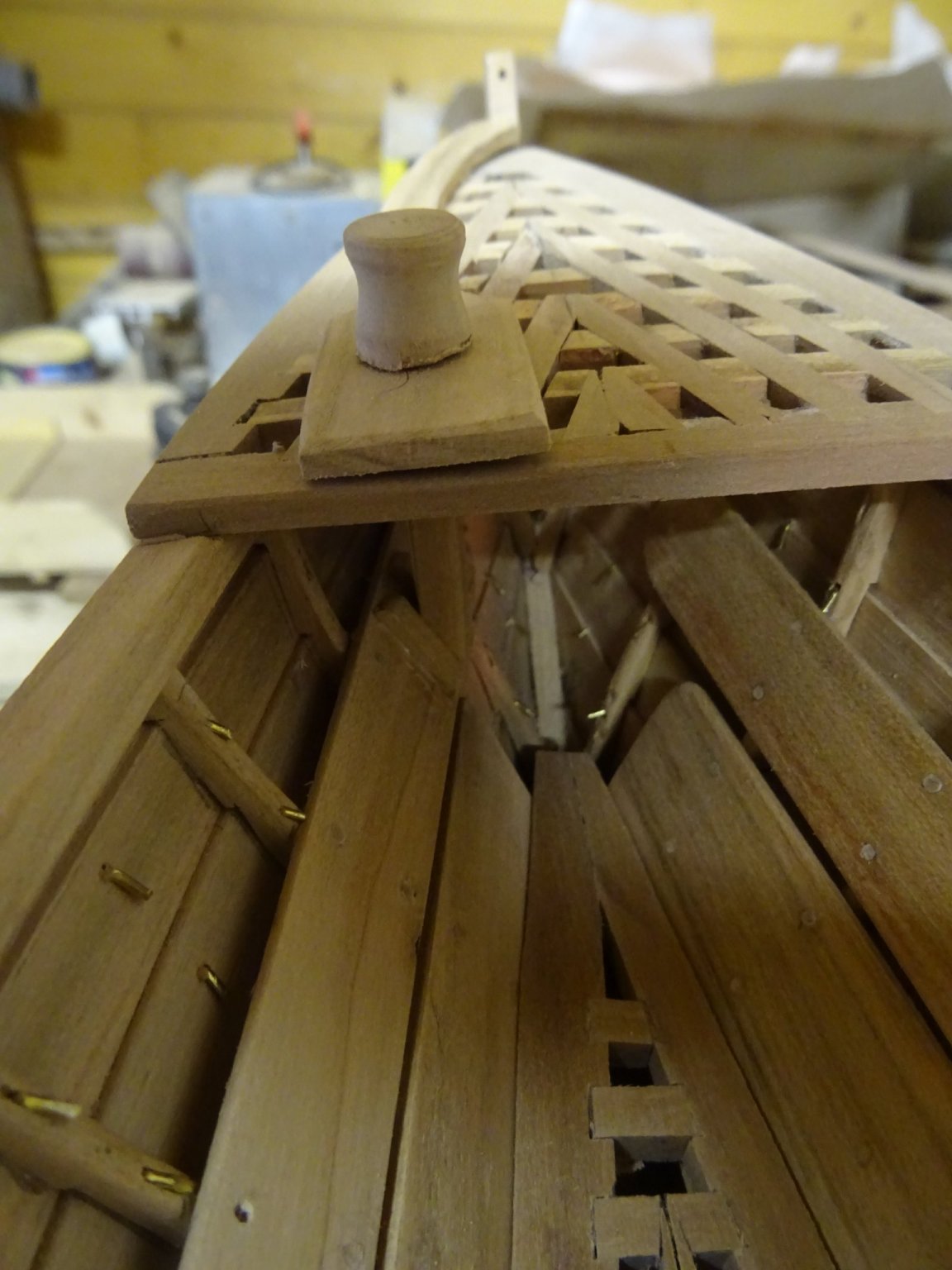
On top of the grating stands a bollard around which the harpoon line runs from forward. In the documentation of Erik Ronnberg the bollard is called the logger head. The logger head post fits into the lion's tongue which reinforces the whole with the stern post.
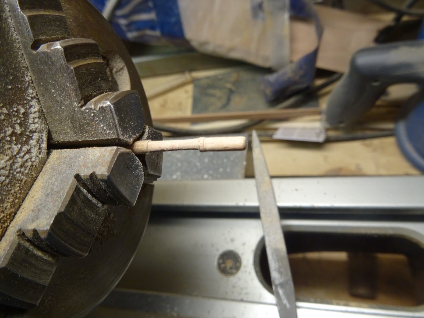
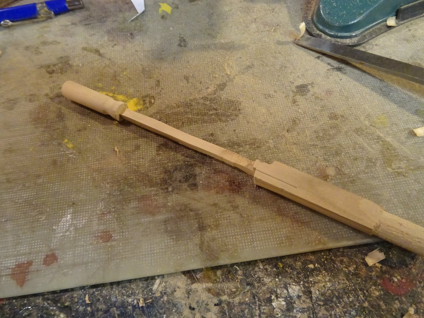
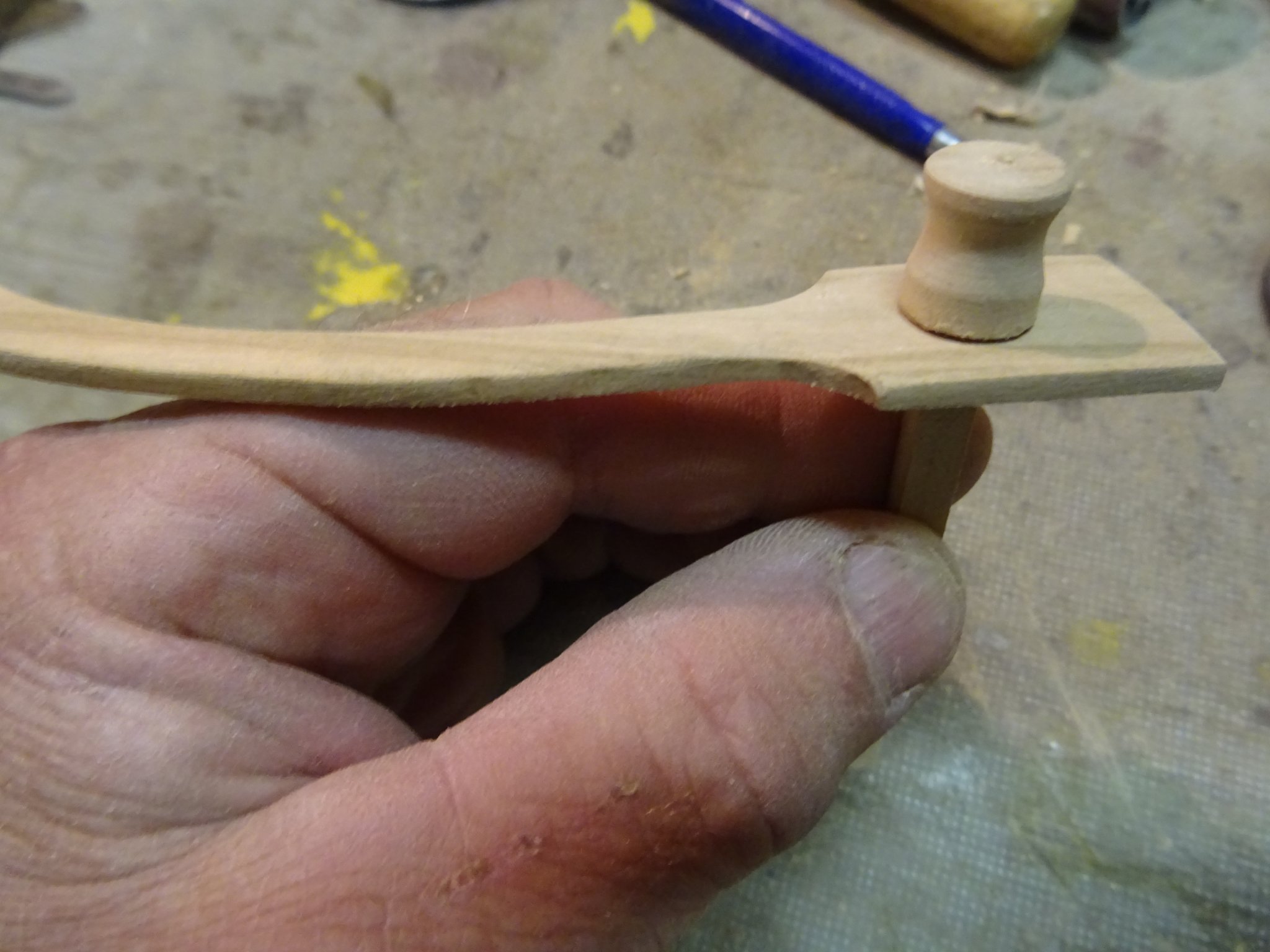
Turning the logger head on the lathe.


Cutting the logger head post.
Fitting the lion's tongue on the after deck.
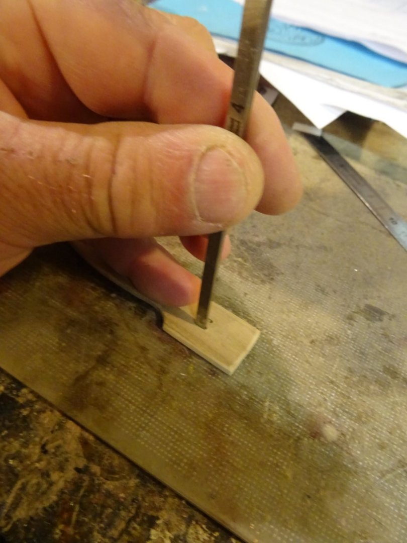
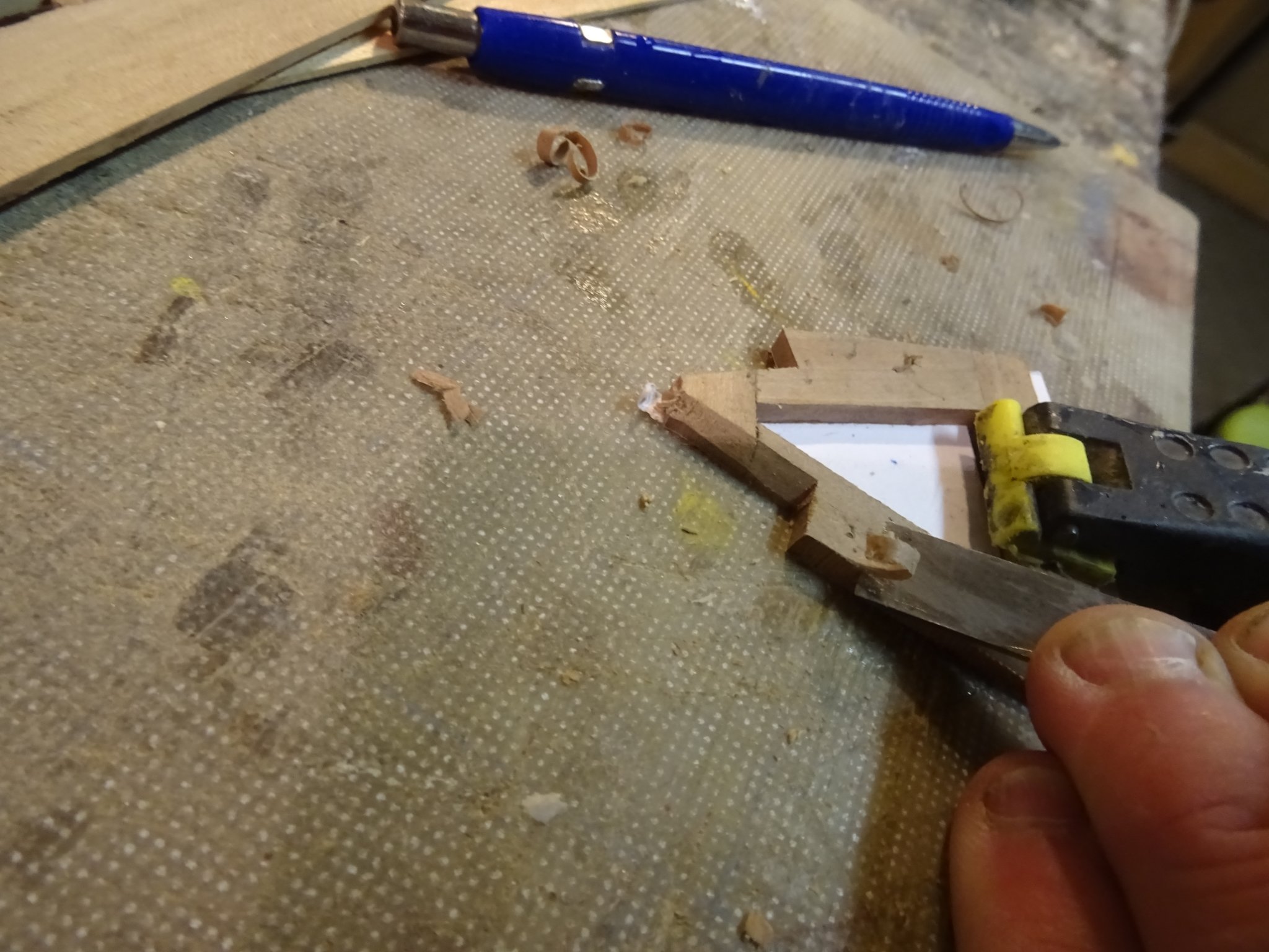
I make the square hole for the logger head post by drilling first a 1 mm hole in the corners to prevent the splitting of the wood during the cutting.

Cutting out the hole with a chisel.
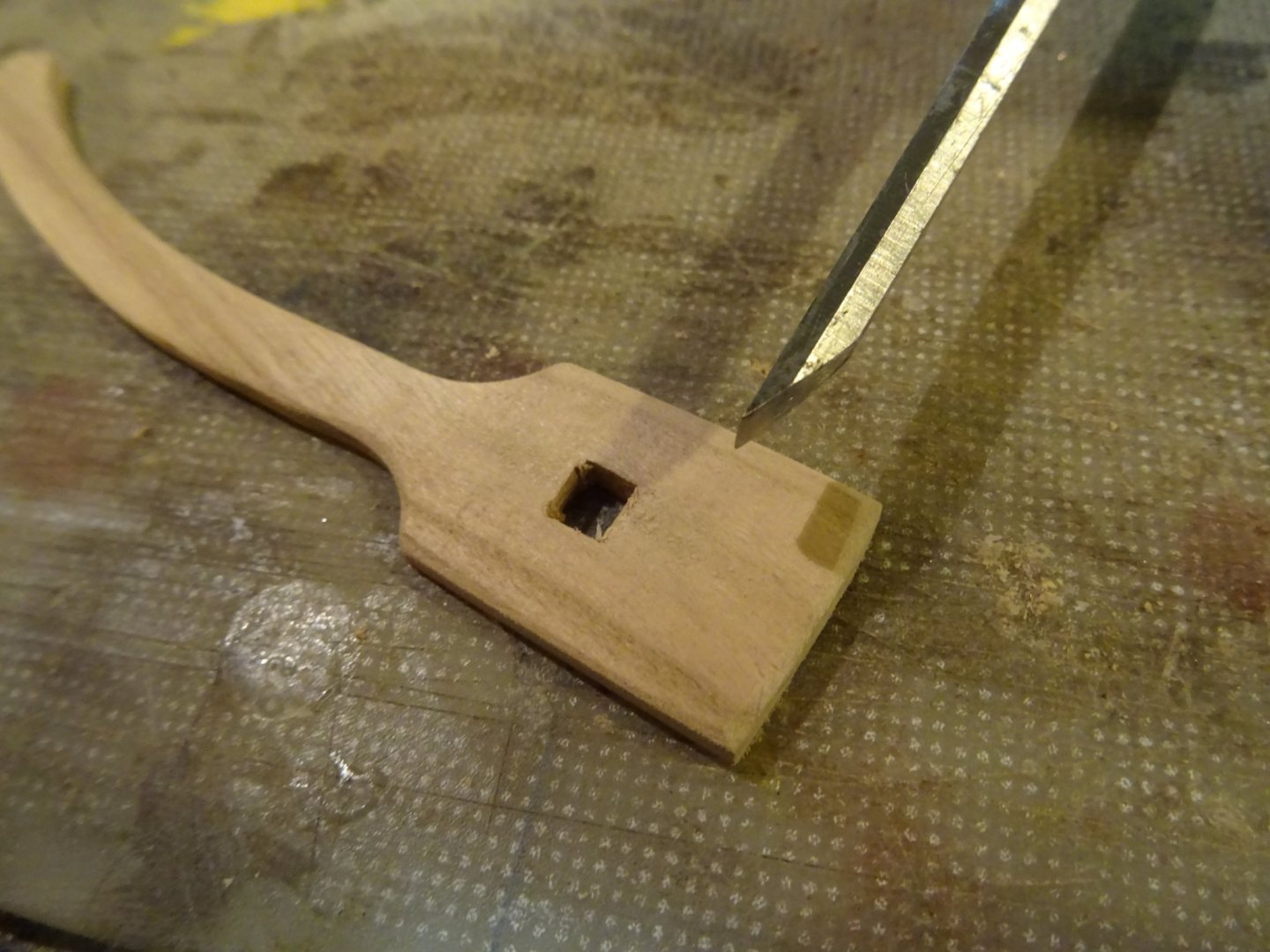
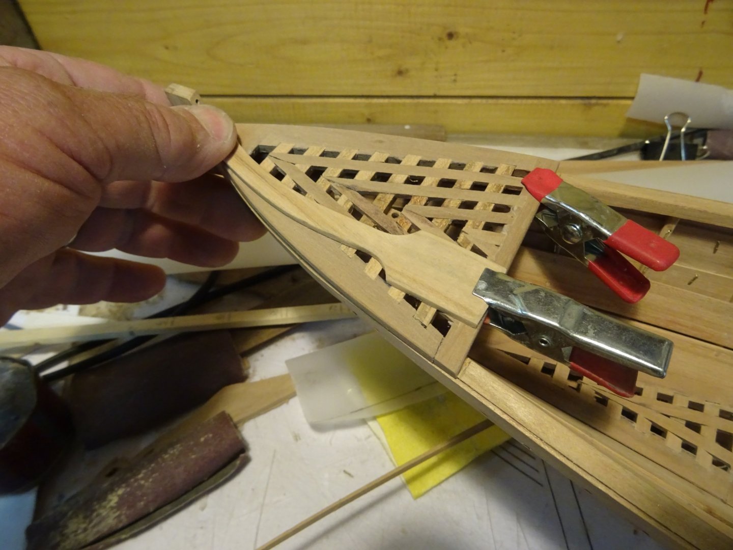
The logger head connected with the lion's tongue.

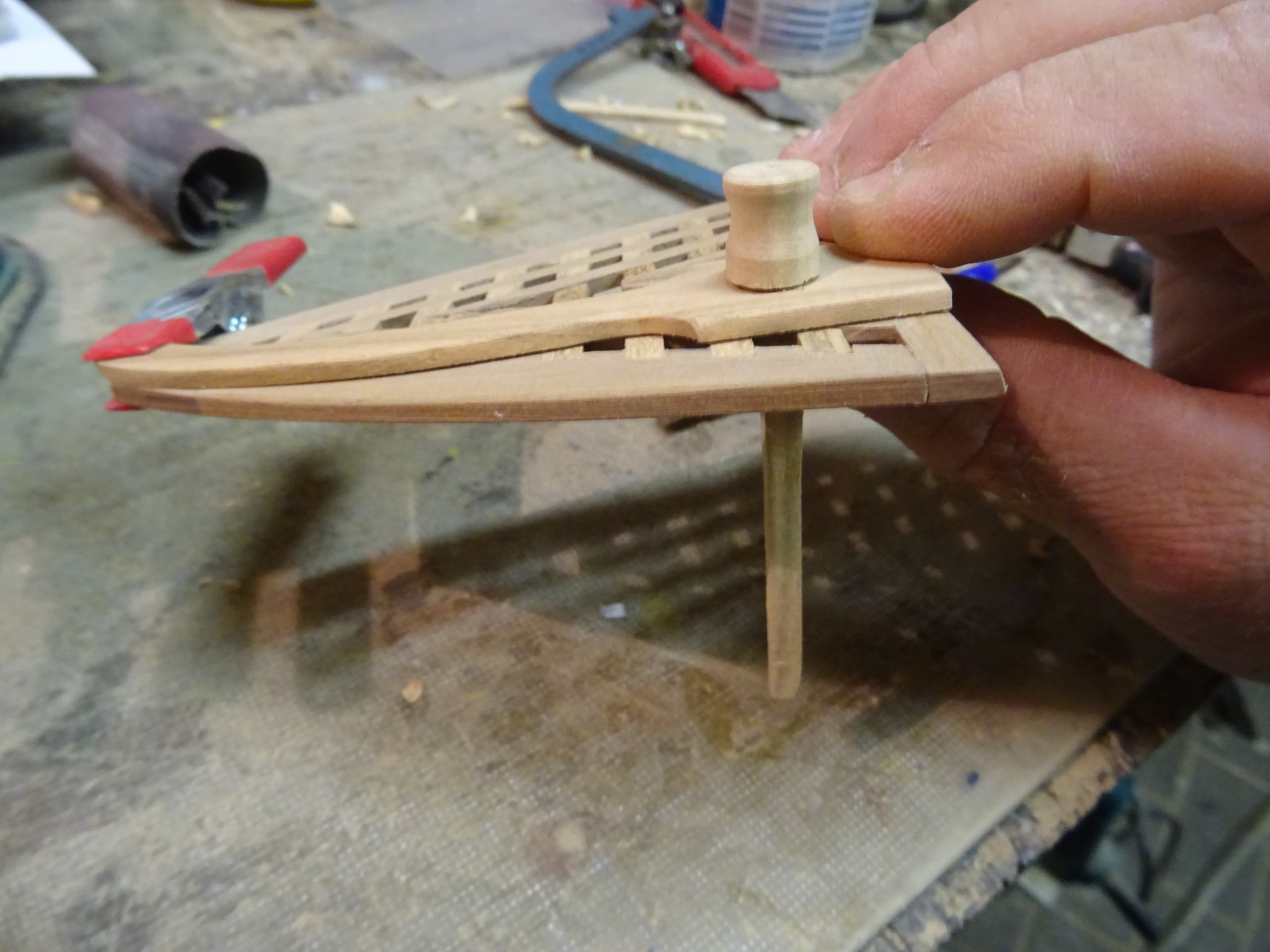
The logger head post goes through the after deck grating, so a hole has to be made in the grating.
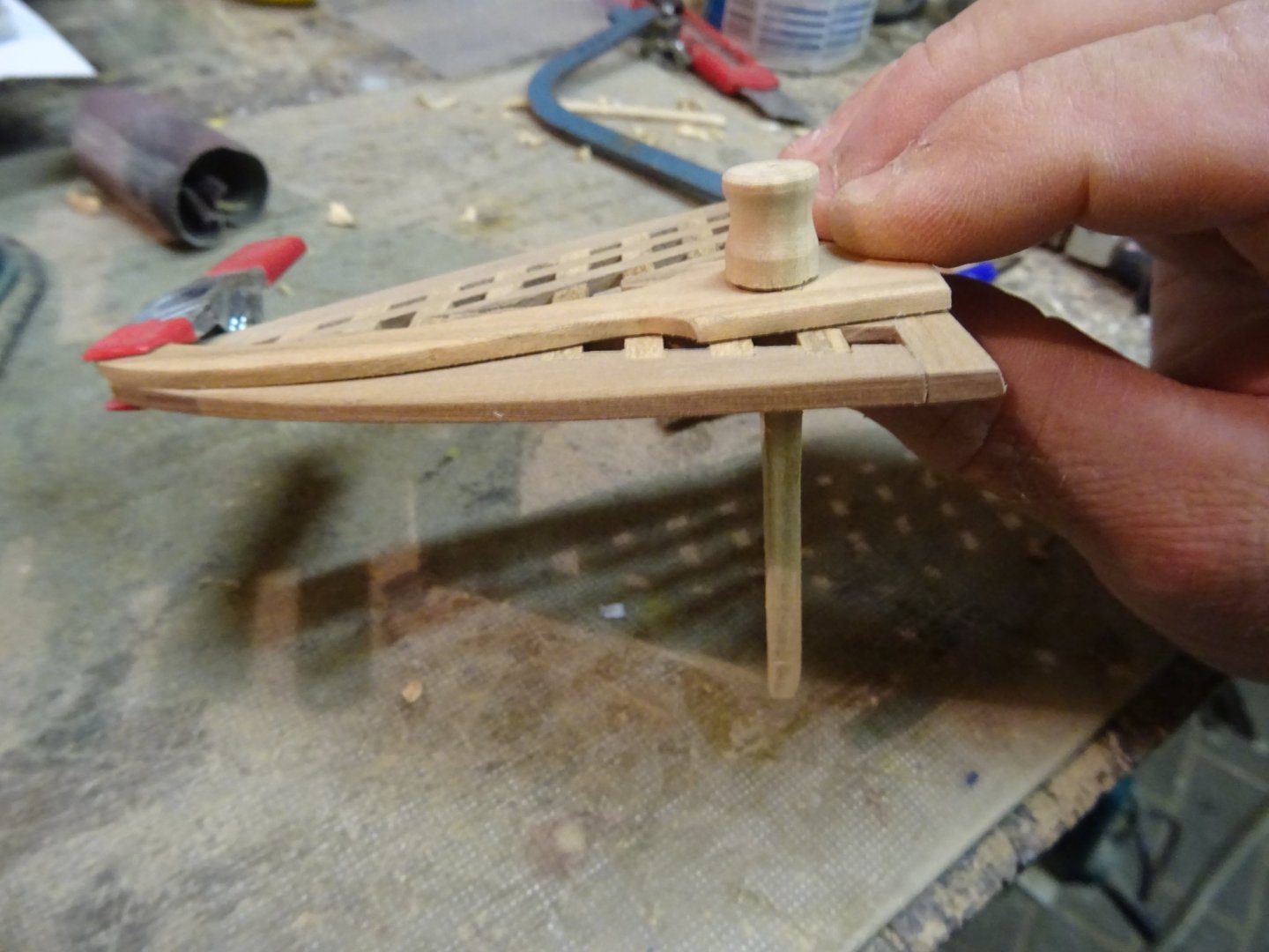
Fitting the whole thing on the model. Nothing is glued yet. The logger head post will be attached to the starboard stringer.
Thank you very much for reading this log and for your likes.
Till next week!
- Blackreed, Baker, GrandpaPhil and 3 others
-
6
-
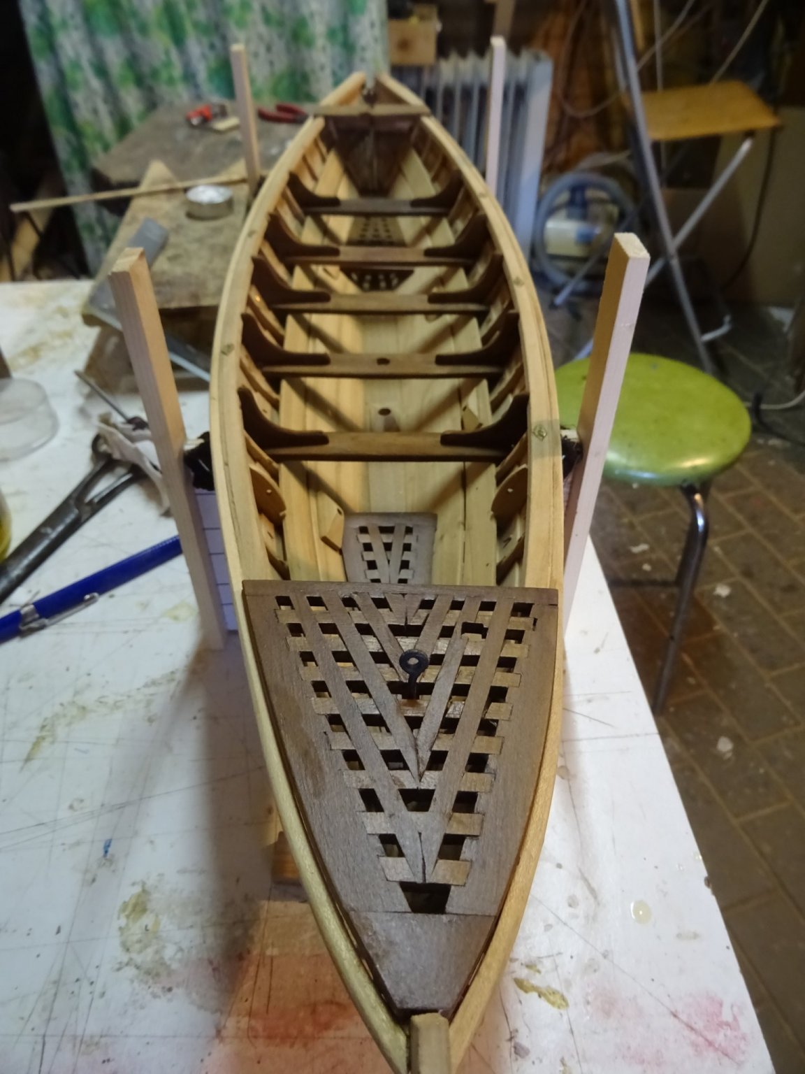
5. The afterdeck
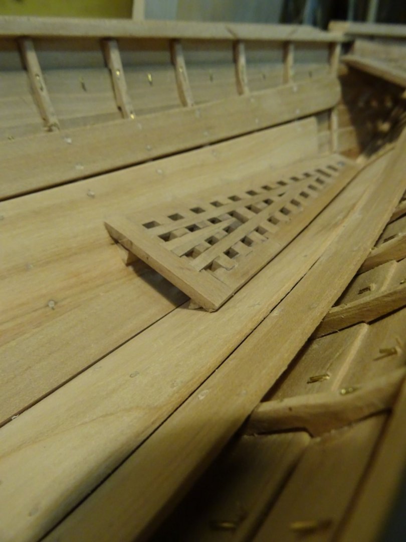
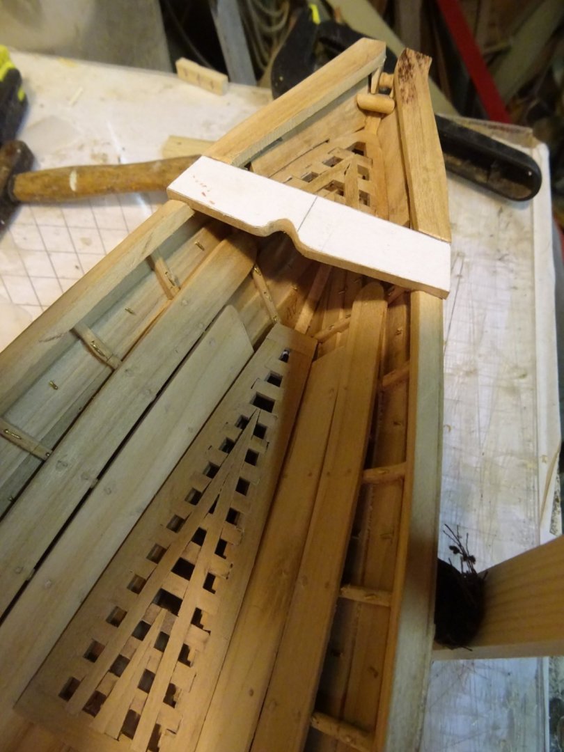
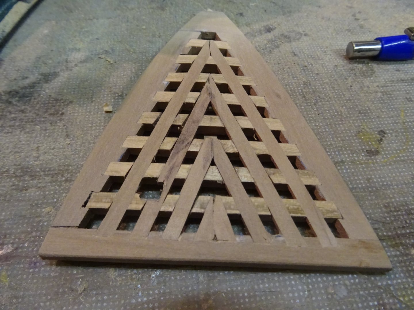
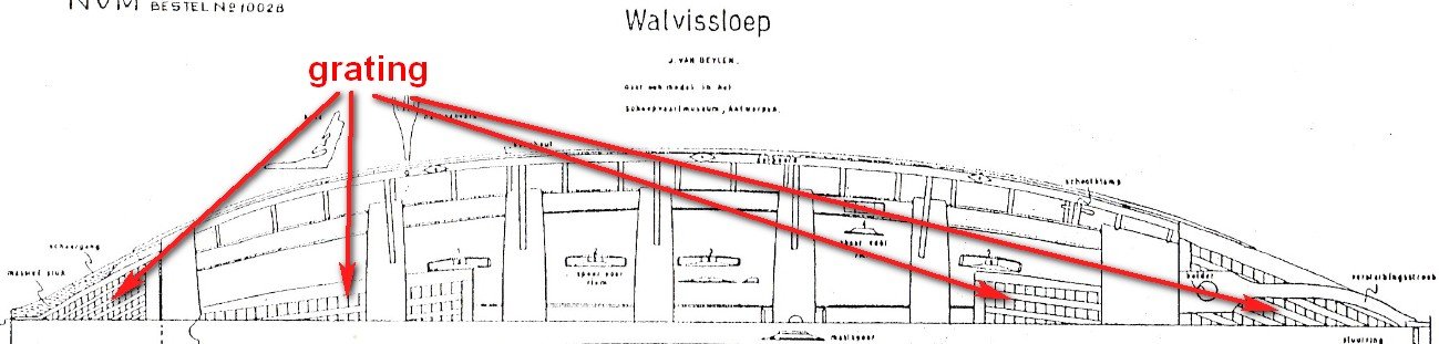
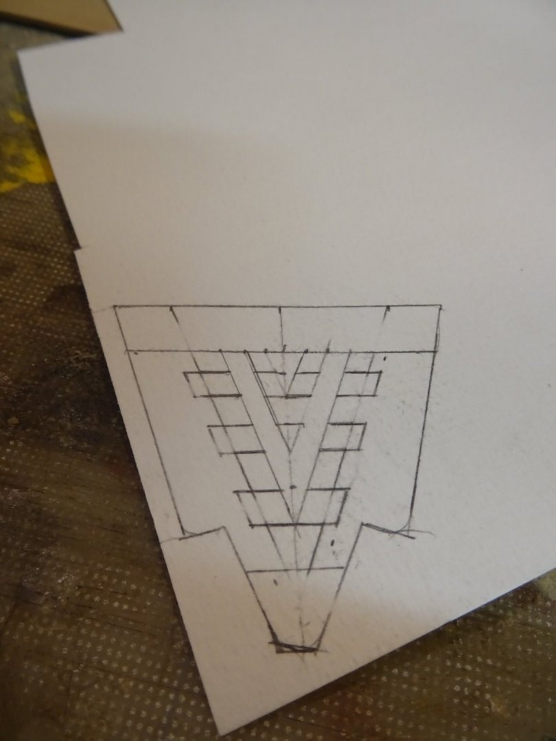
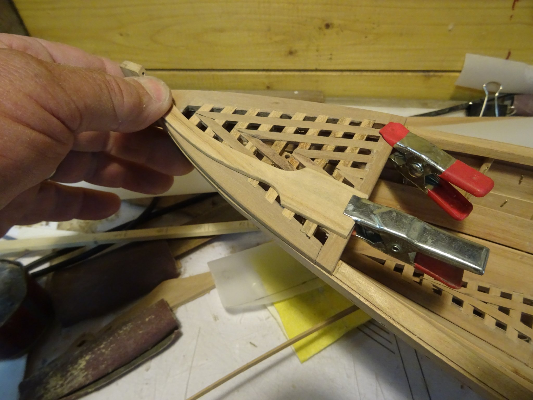
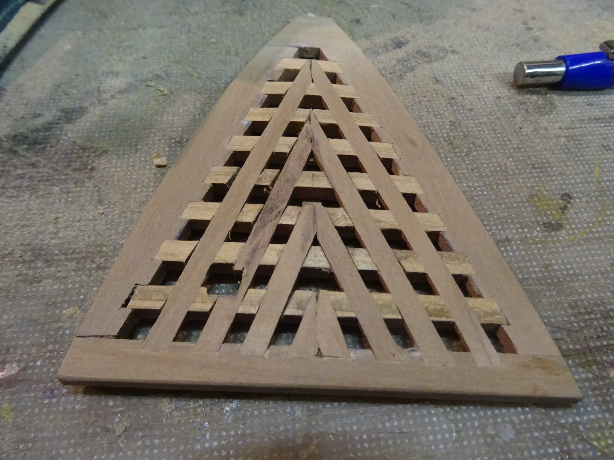
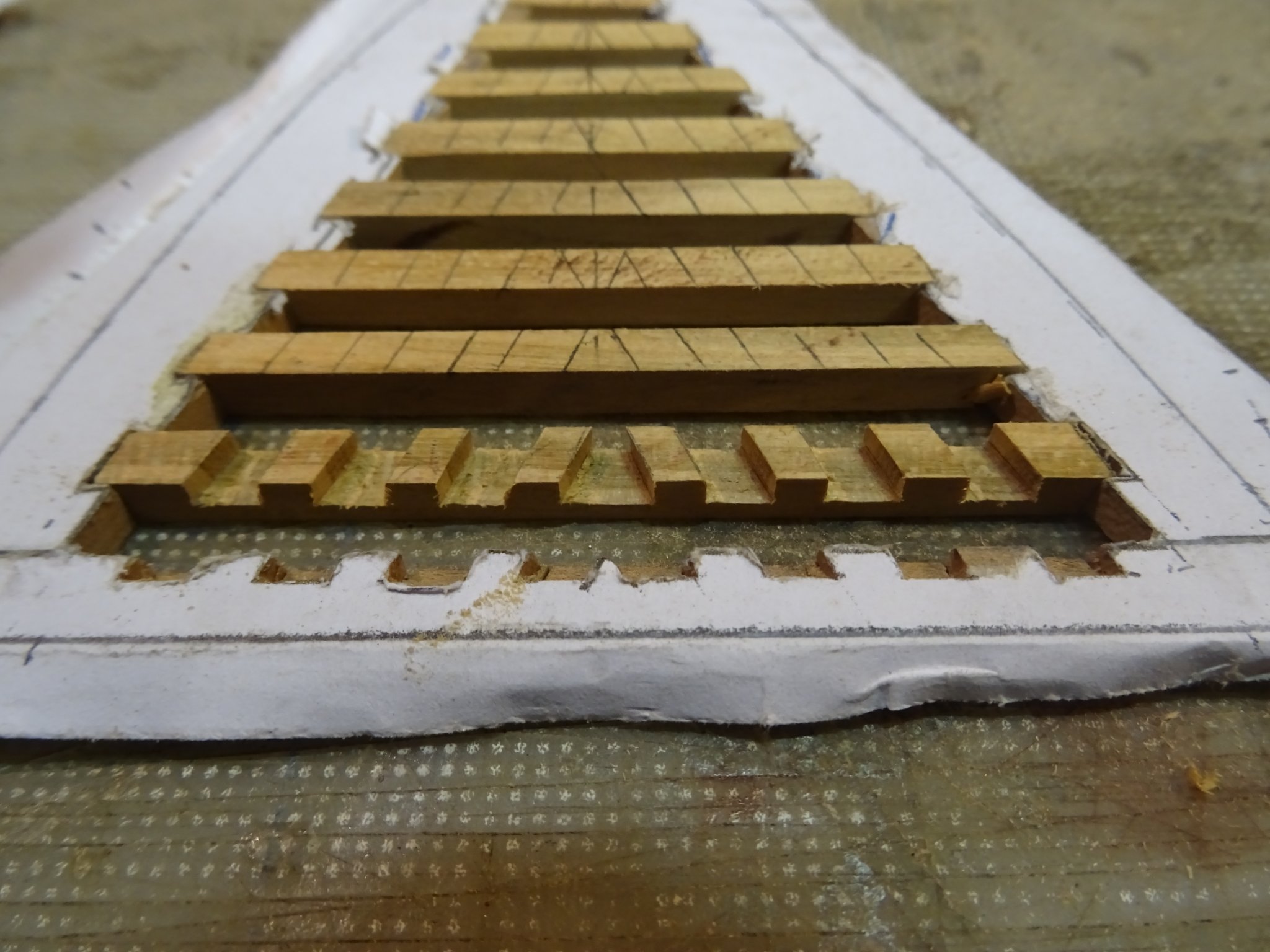
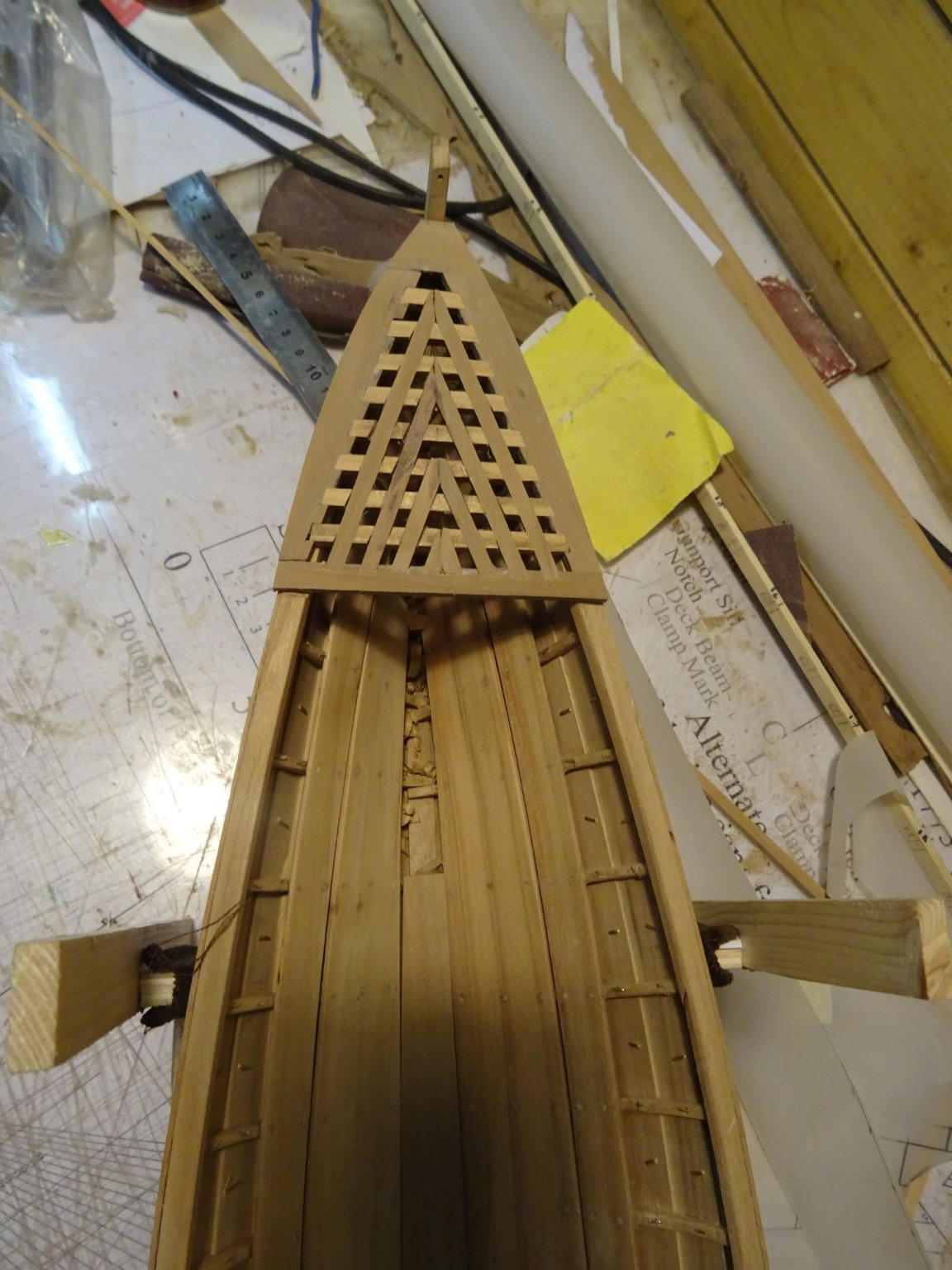
Now I will make the aft deck arrangements. The aft deck is mainly covered by a grating.
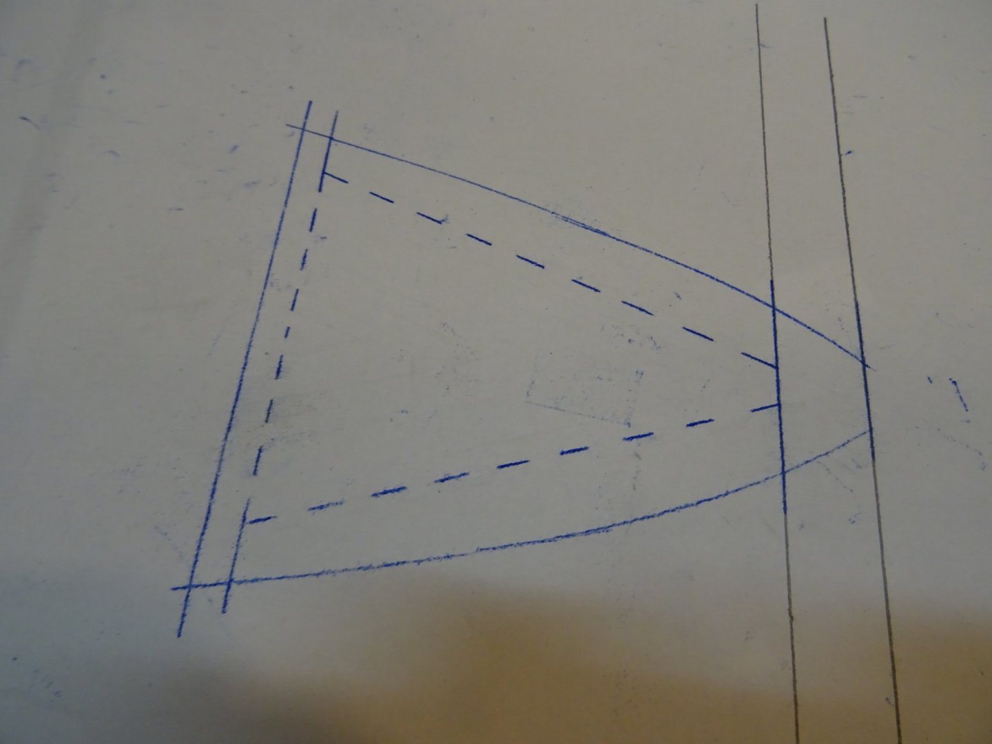
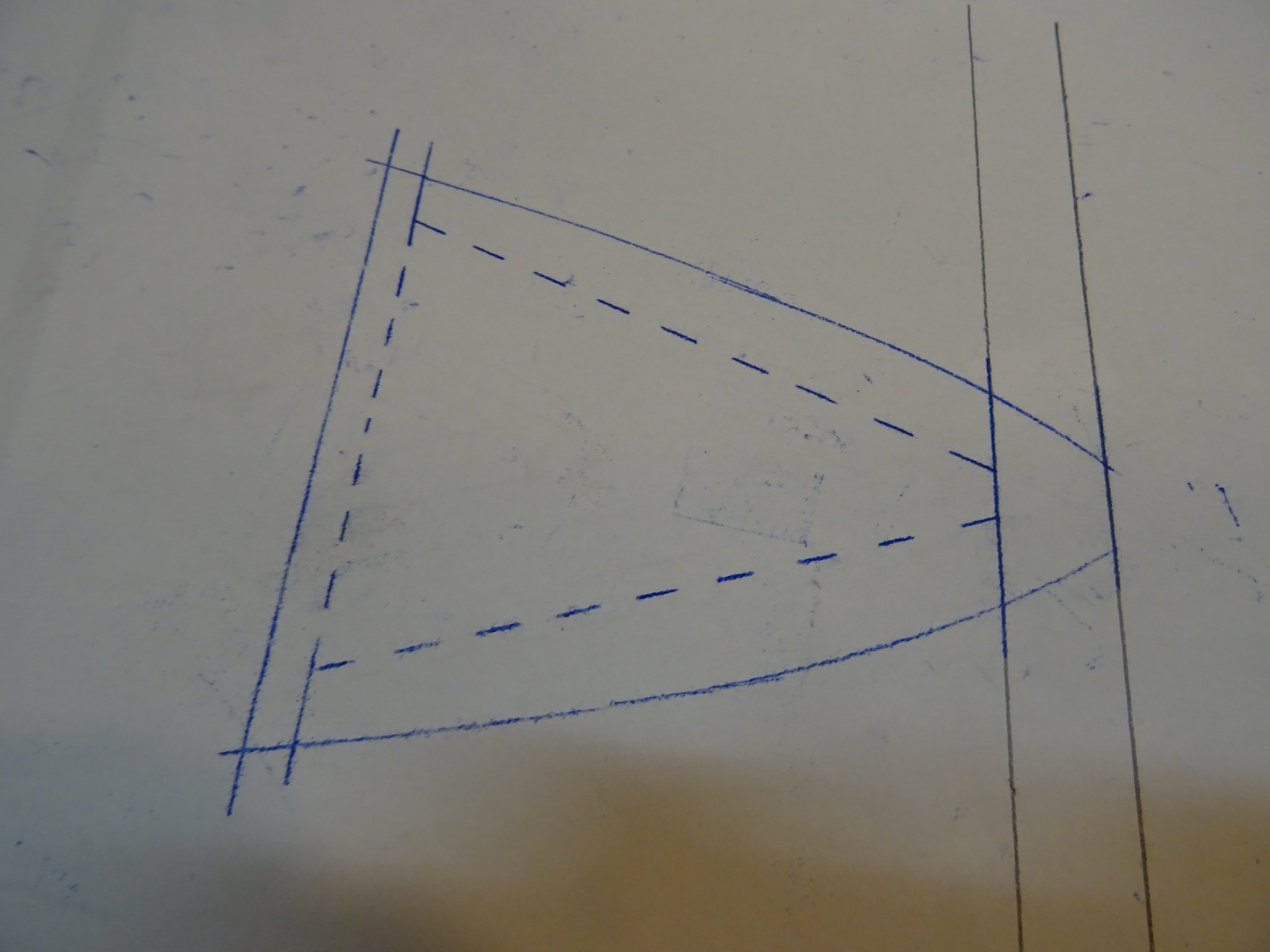
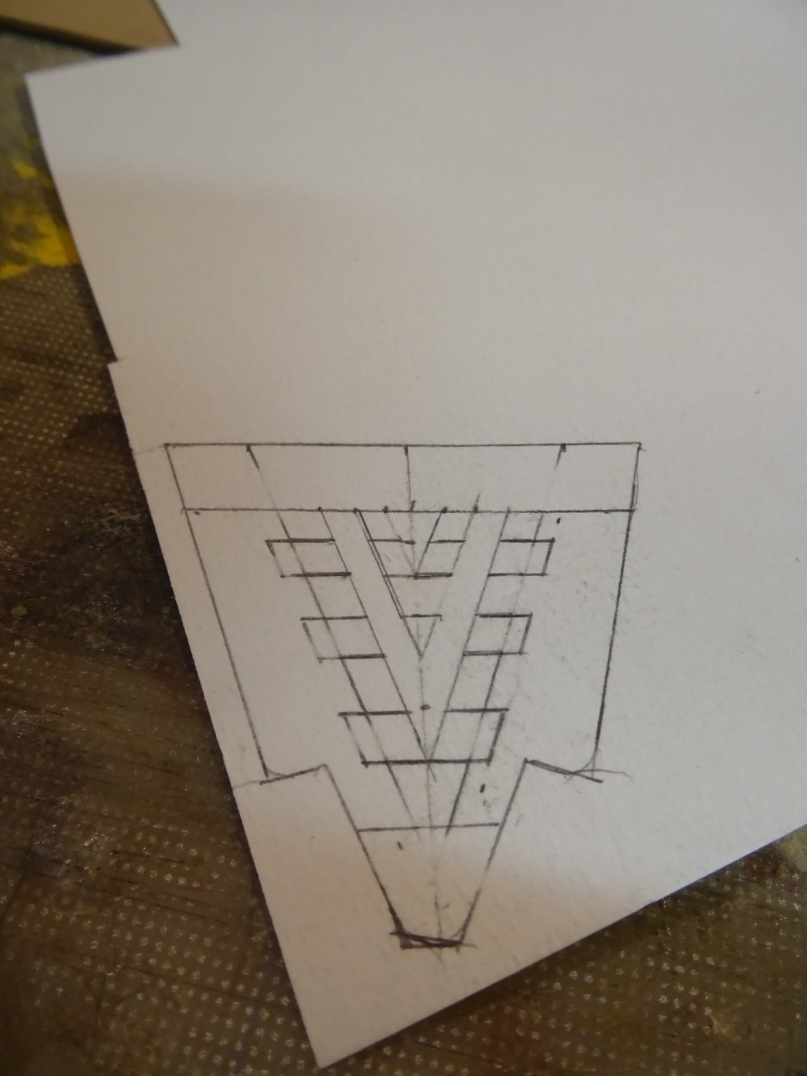
As you see the drawing on the plan is not very detailed, so I start with making a more detailed drawing.
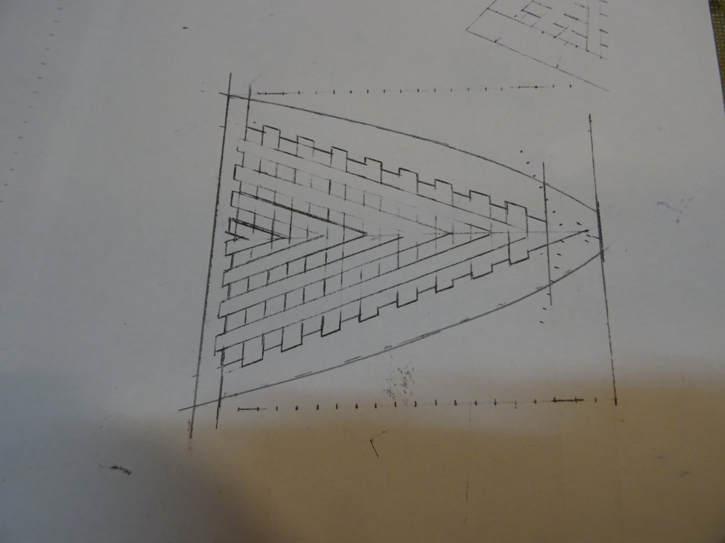
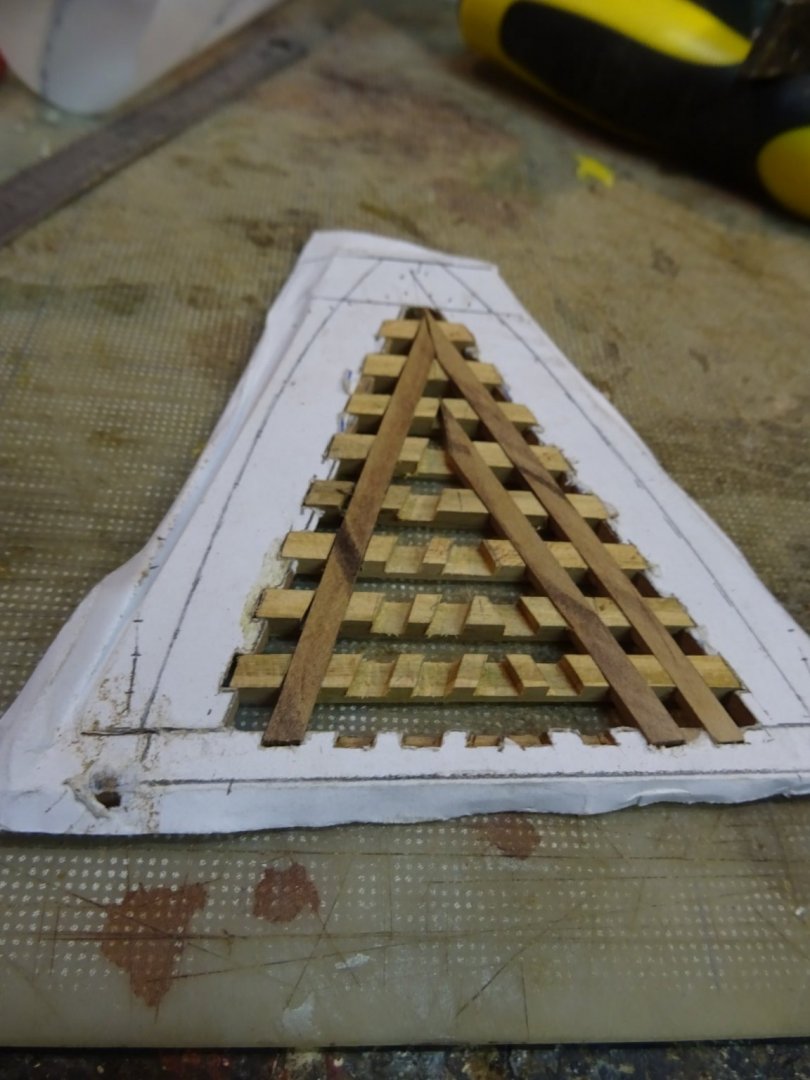
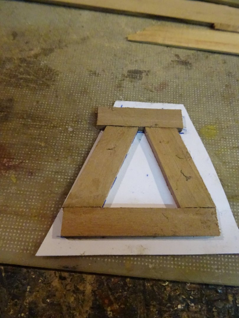
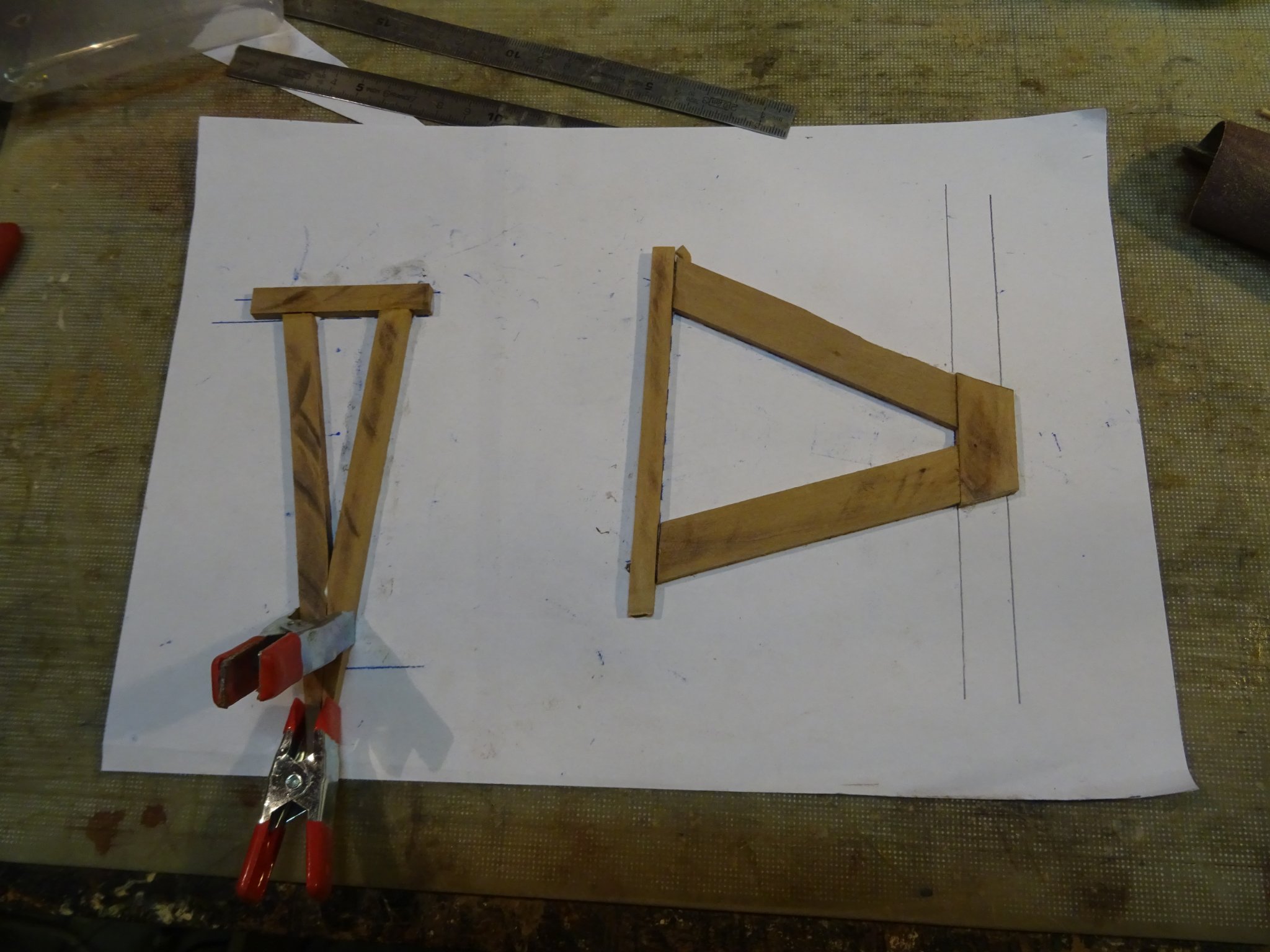
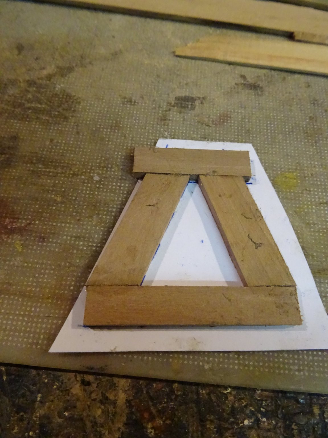
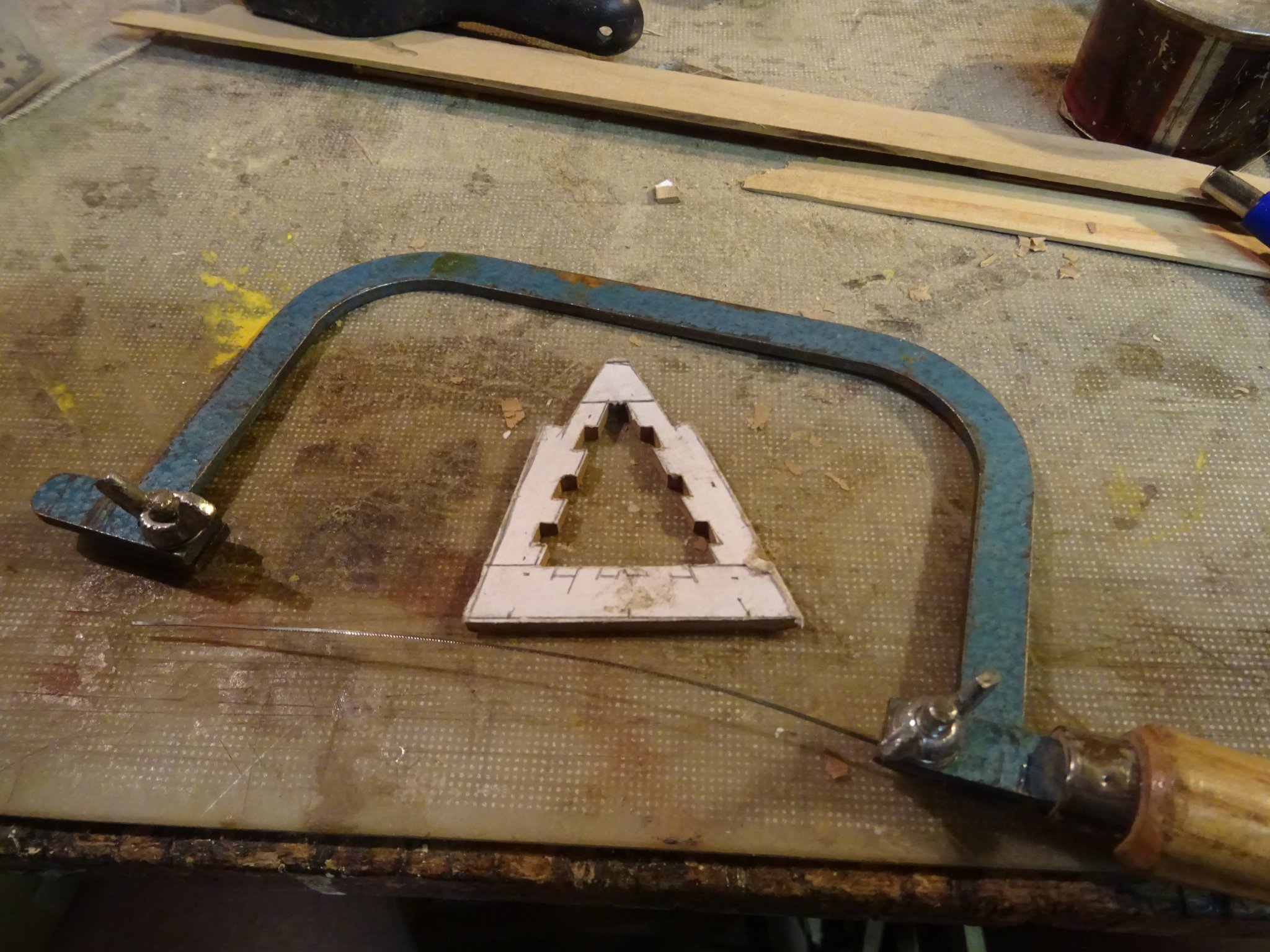
With the help of carbon paper, I push through the outlines of grating frame on the backside of the paper and glue the wood for the frame on that back side. On the left side of the same paper you see the preparation of one of the other gratings.
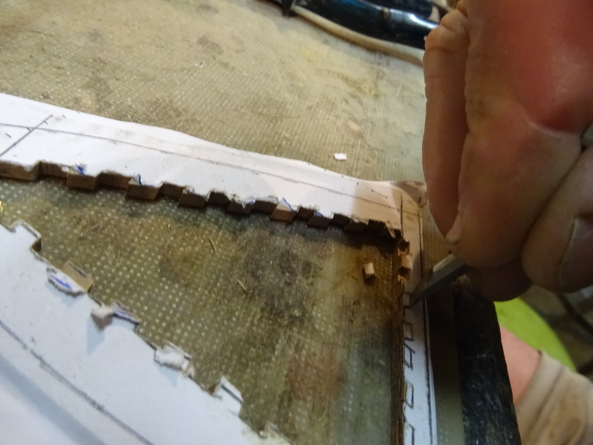
It is the same process as for the forward grating. Sawing out the notches for the bars.
Cutting the notches for the cross bars with a small wood chisel.

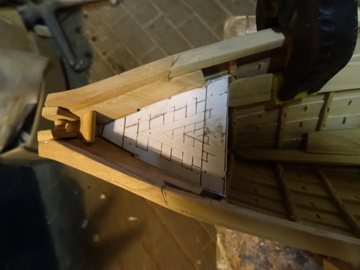
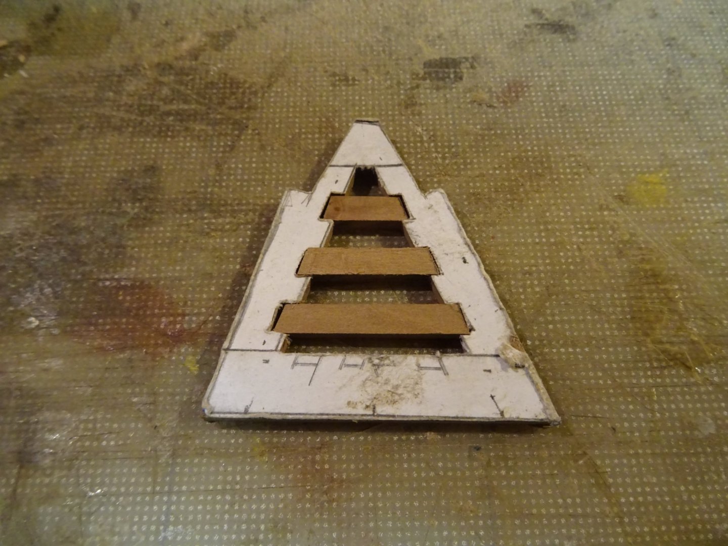
Making and fitting the bars.
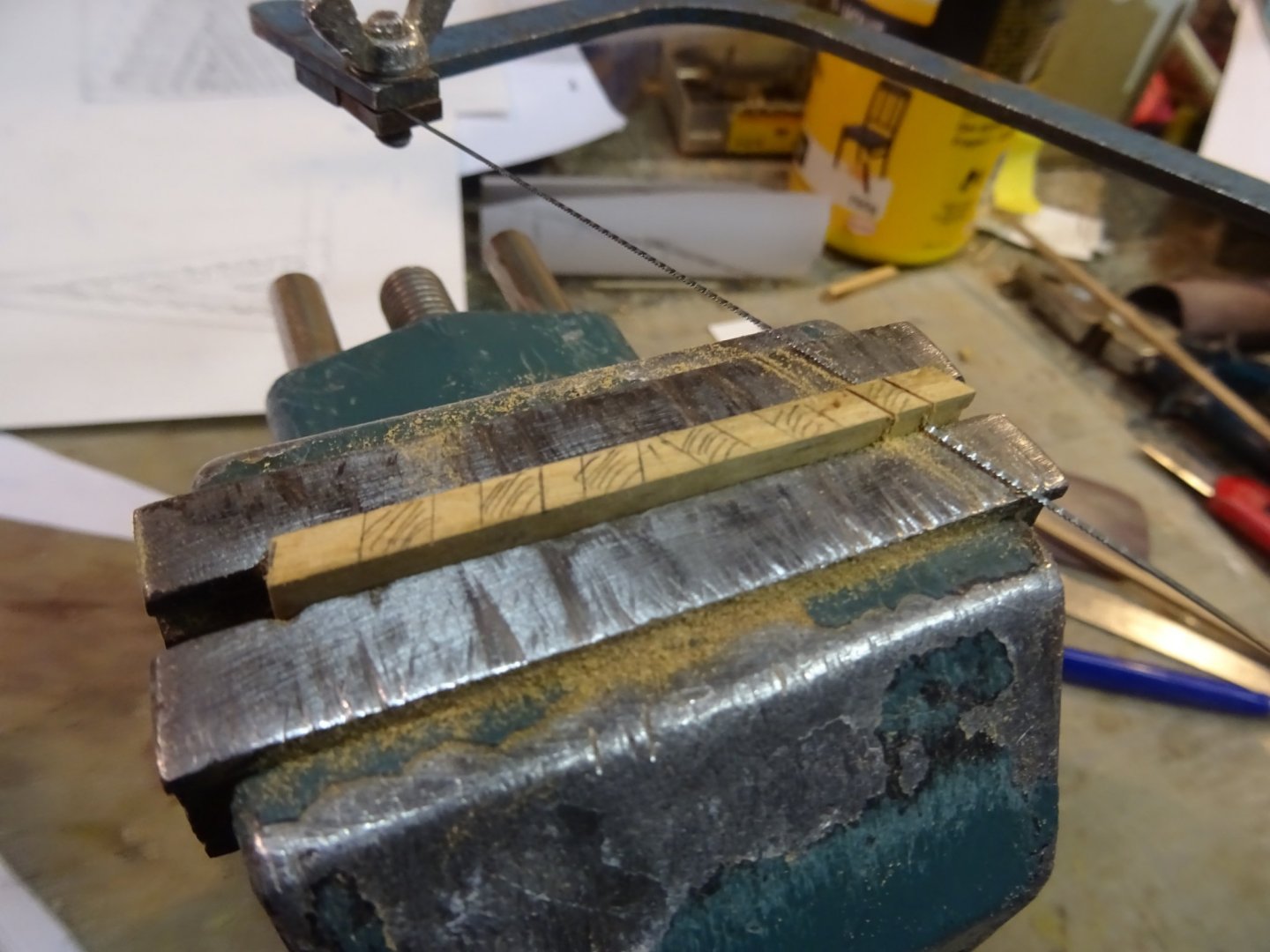
The cross bars have to fit in the bars. I saw the notches out with the help of a vice for the depth adjustment.

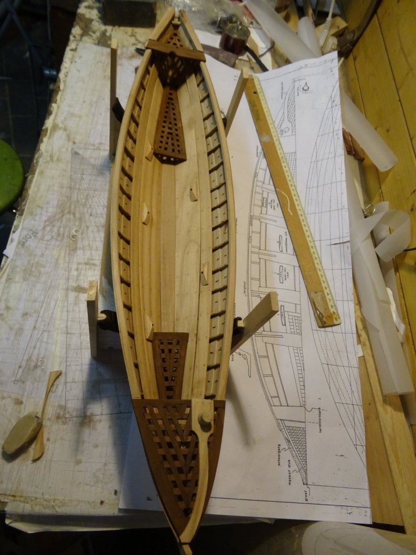
Fitting the grating on, the model.

- mtaylor, Baker, GrandpaPhil and 2 others
-
5
-
-
Again and an example of beautiful precision work!
- KeithAug, mtaylor, FriedClams and 1 other
-
4
-
-
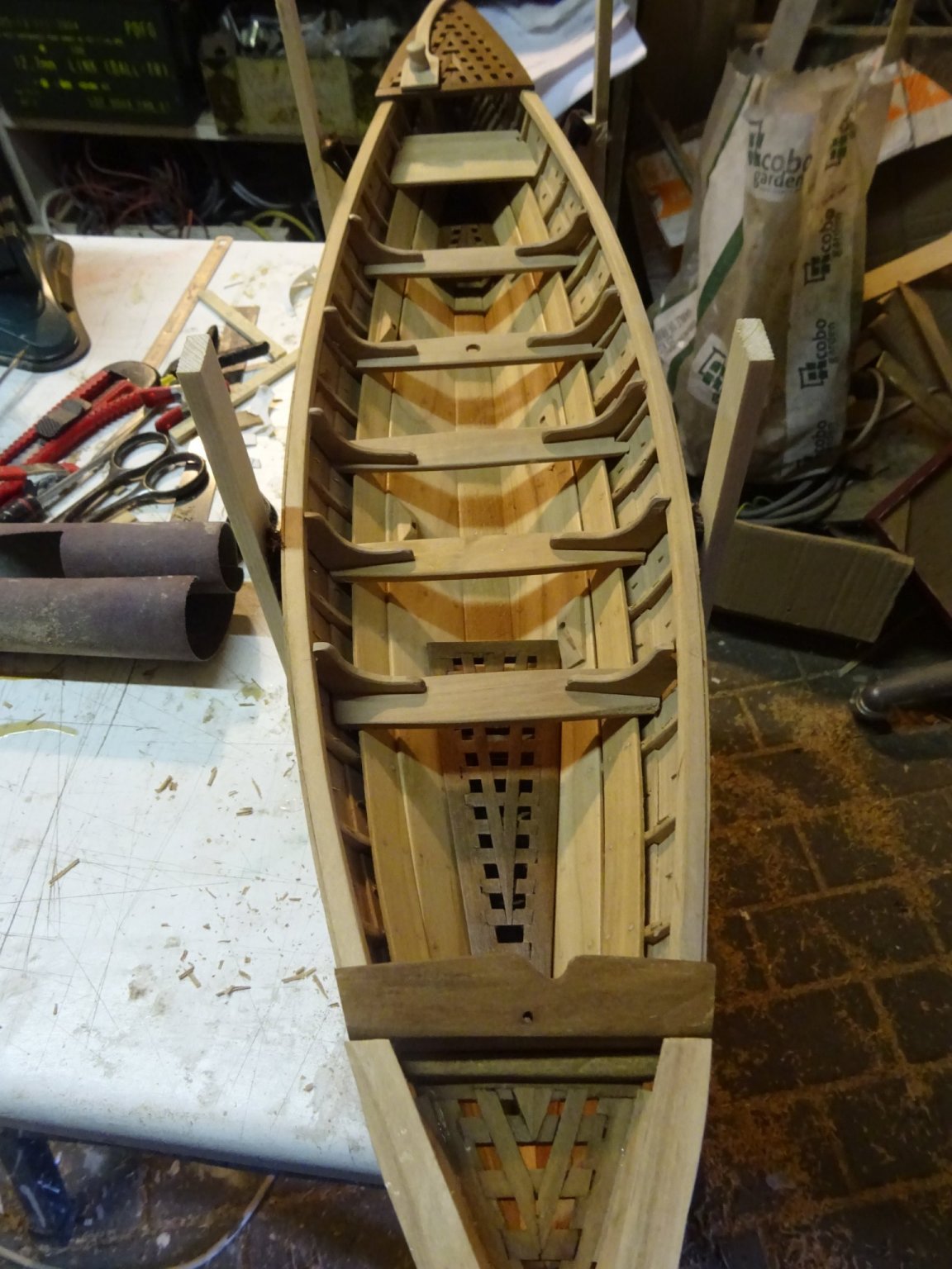
4. Interior of the hull
On this type of whale boat all platforms are gratings. Four have to be made.
Now it is time to make the forward one.
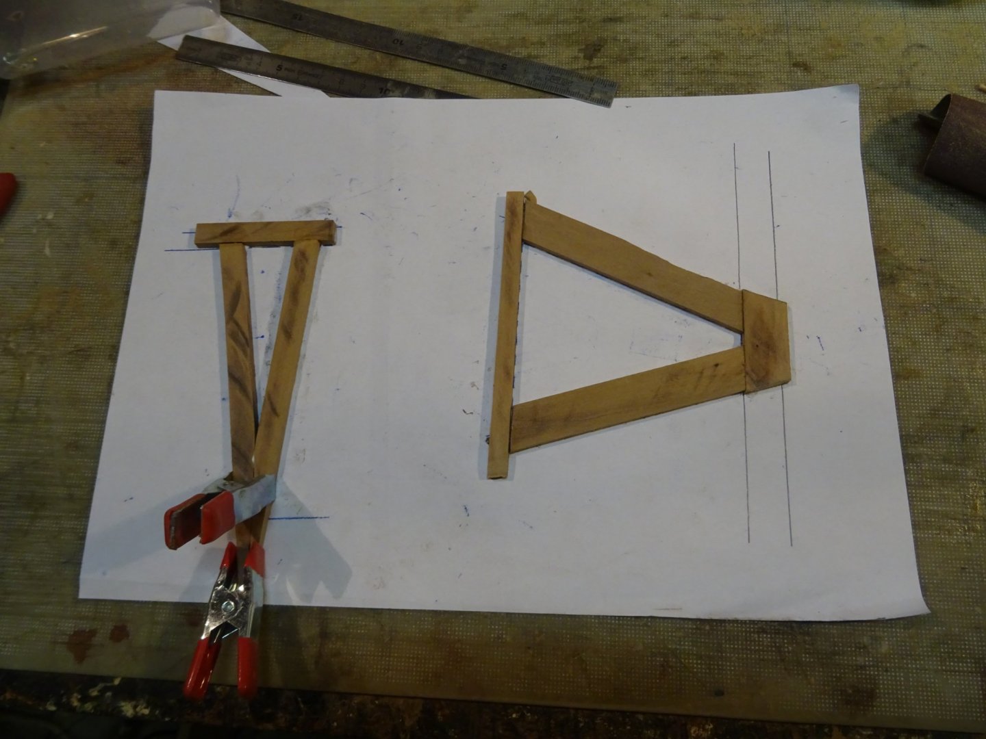
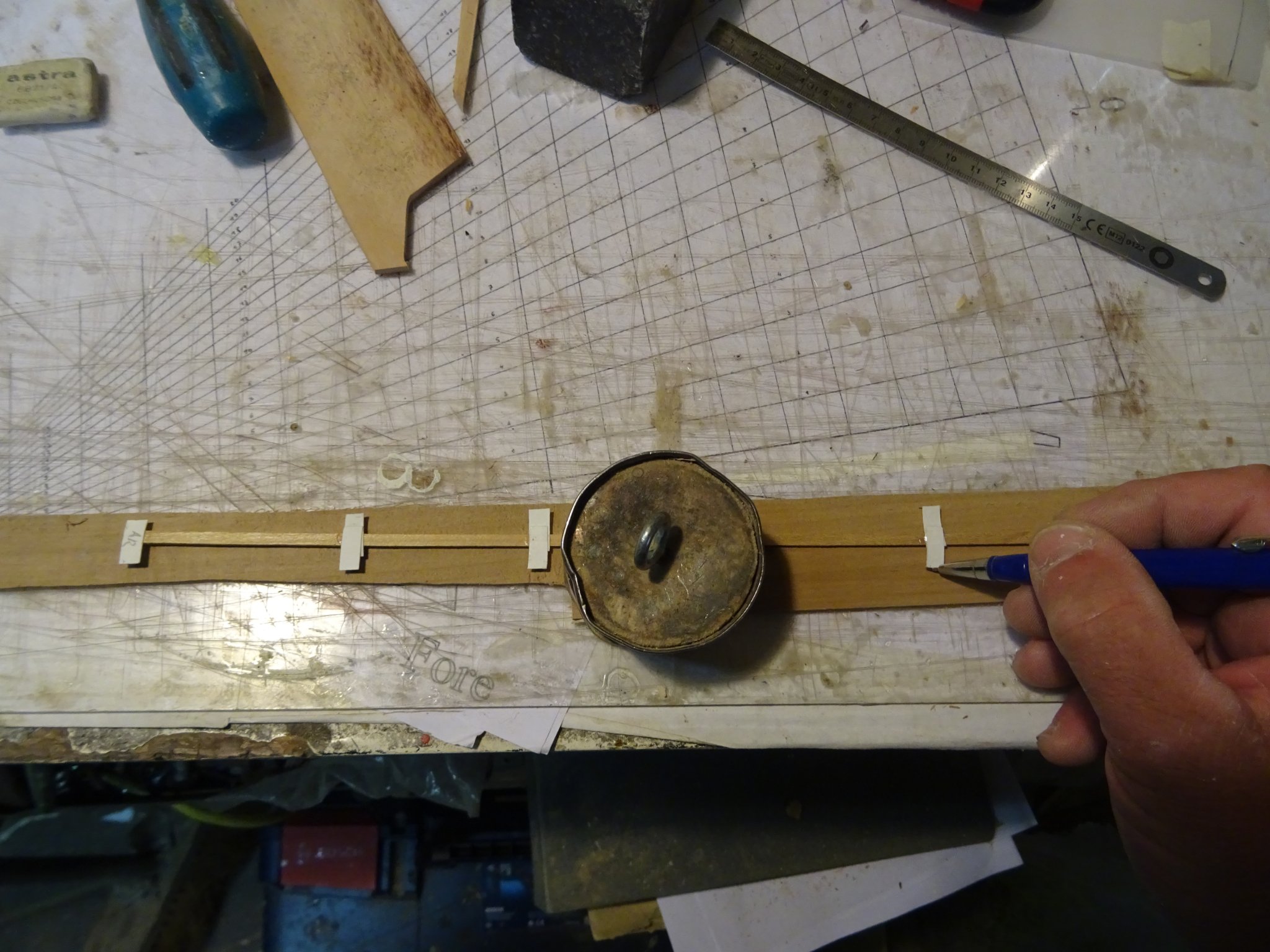
I make first a template with strips of drawing paper to determine the shape of the grating.
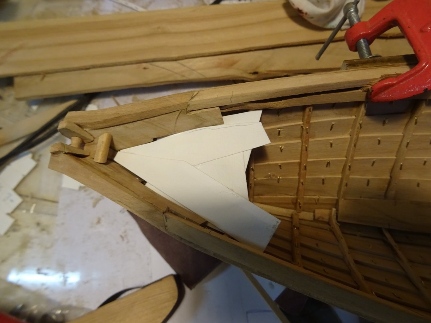
With the help of that template I make a drawing of the grating.
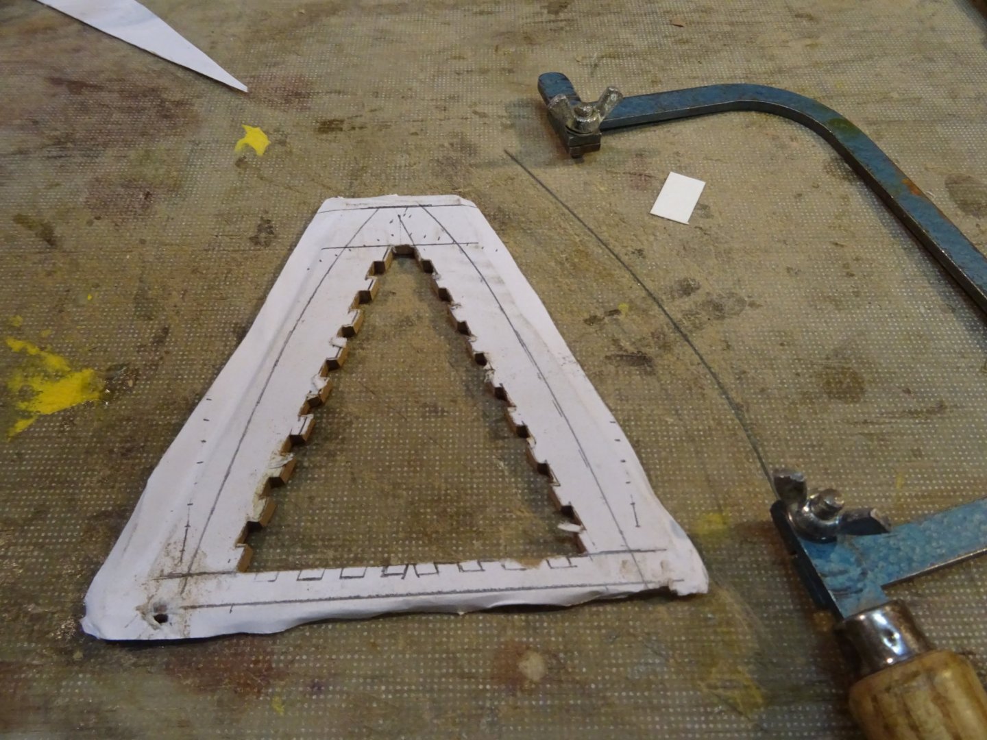
On the reverse side of that drawing I glue the frame planks of the grating and saw them in the desired shape. The sides have to be chamfered a bit because the space in which they have to fit is oblique.

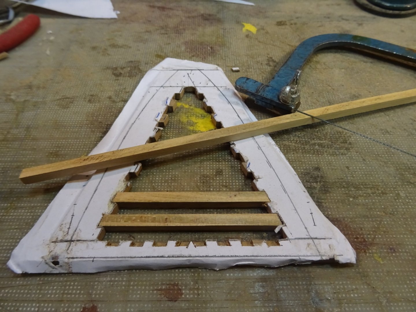
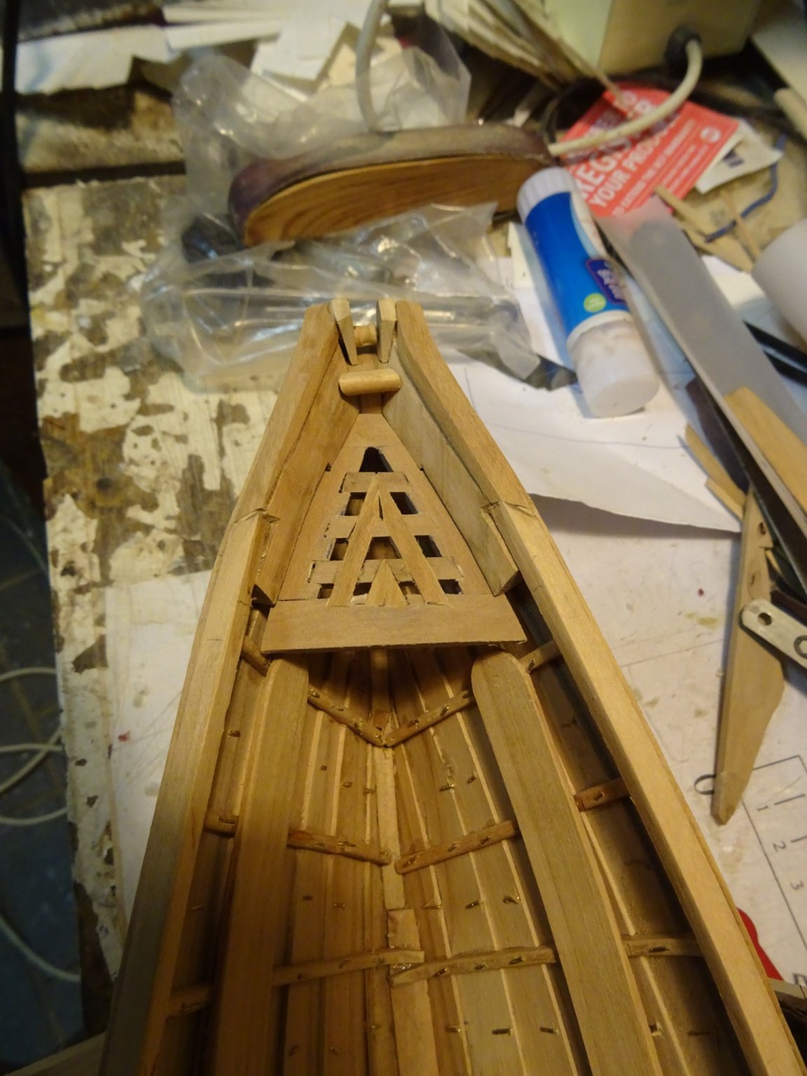
This is the top side of the grating. I am sawing out the spaces for the intermediate divisions.

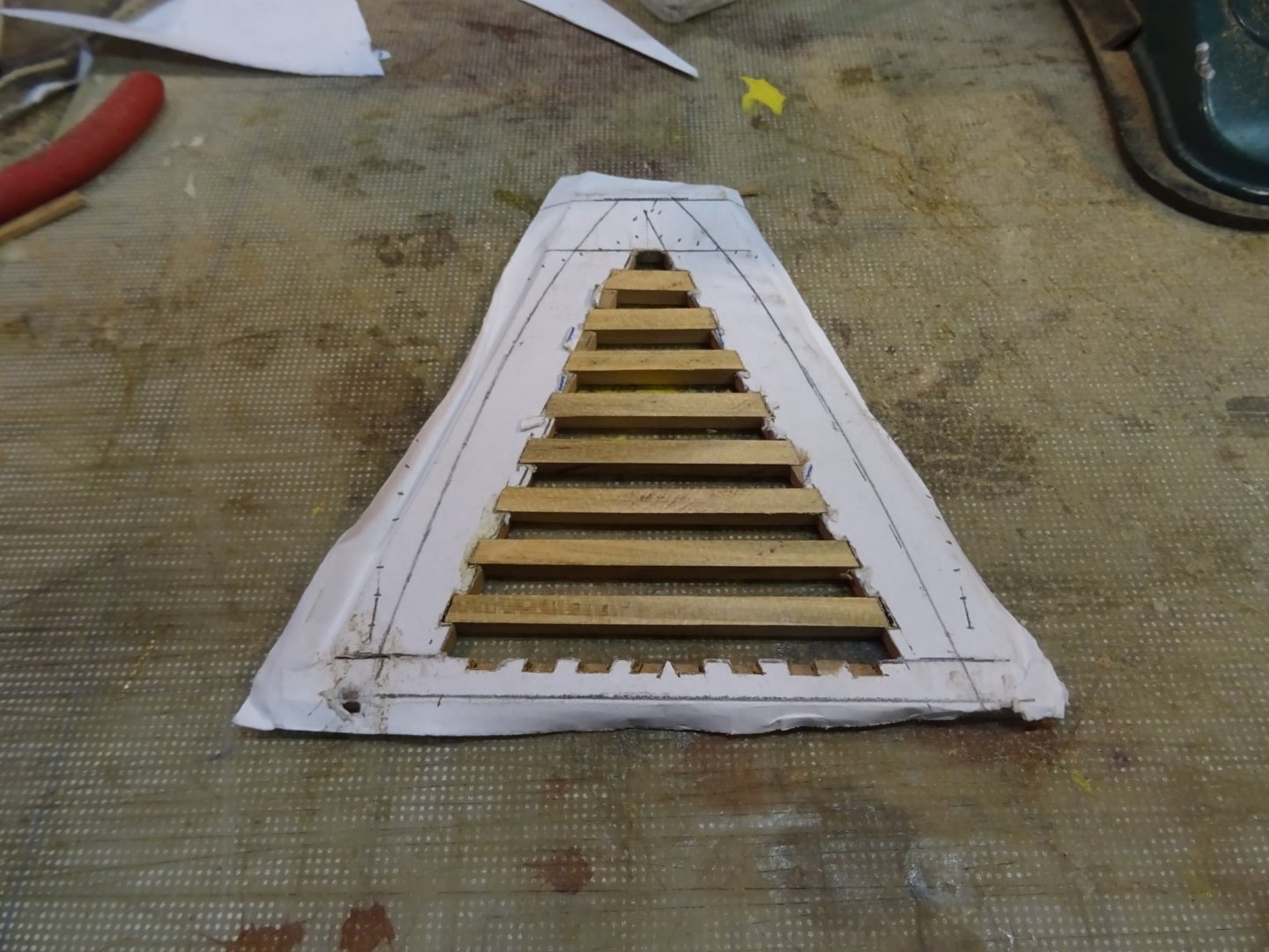
Fitting the intermediate divisions in it.
And finally the grating into position.

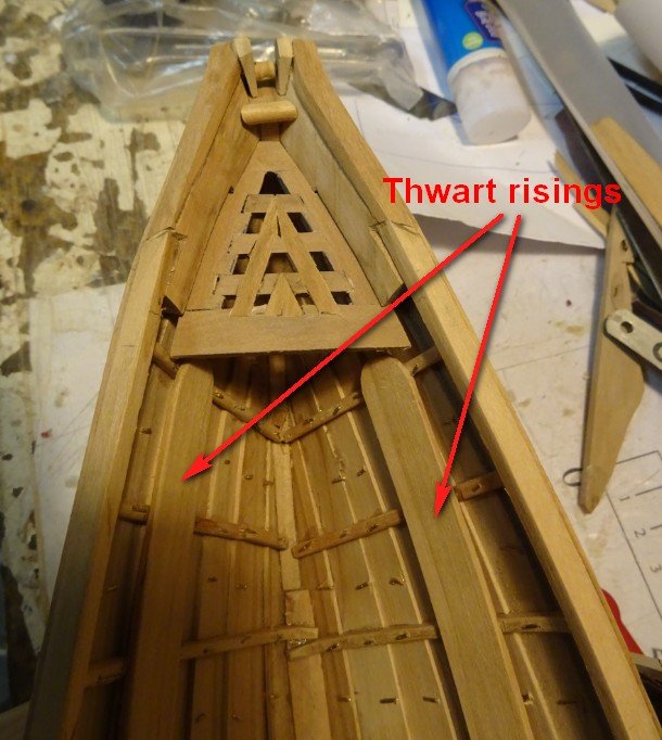
On this picture you can see that the thwart risings are also allready placed at both sides.
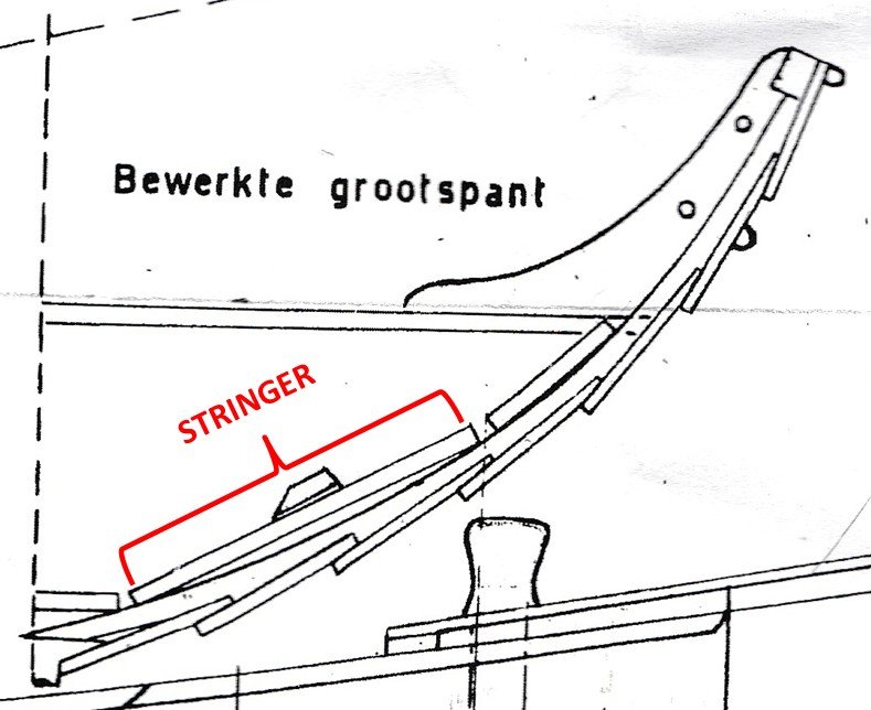
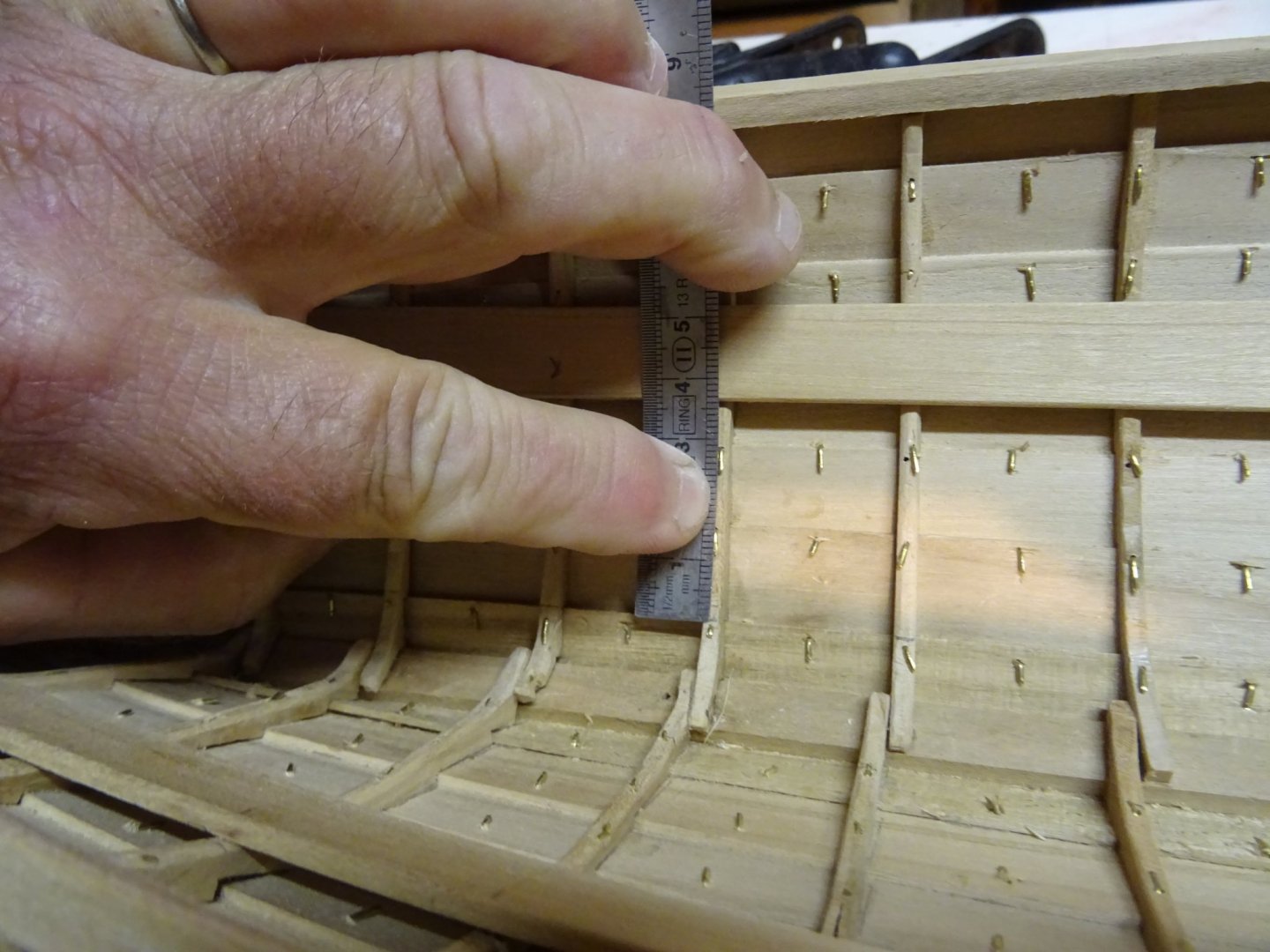
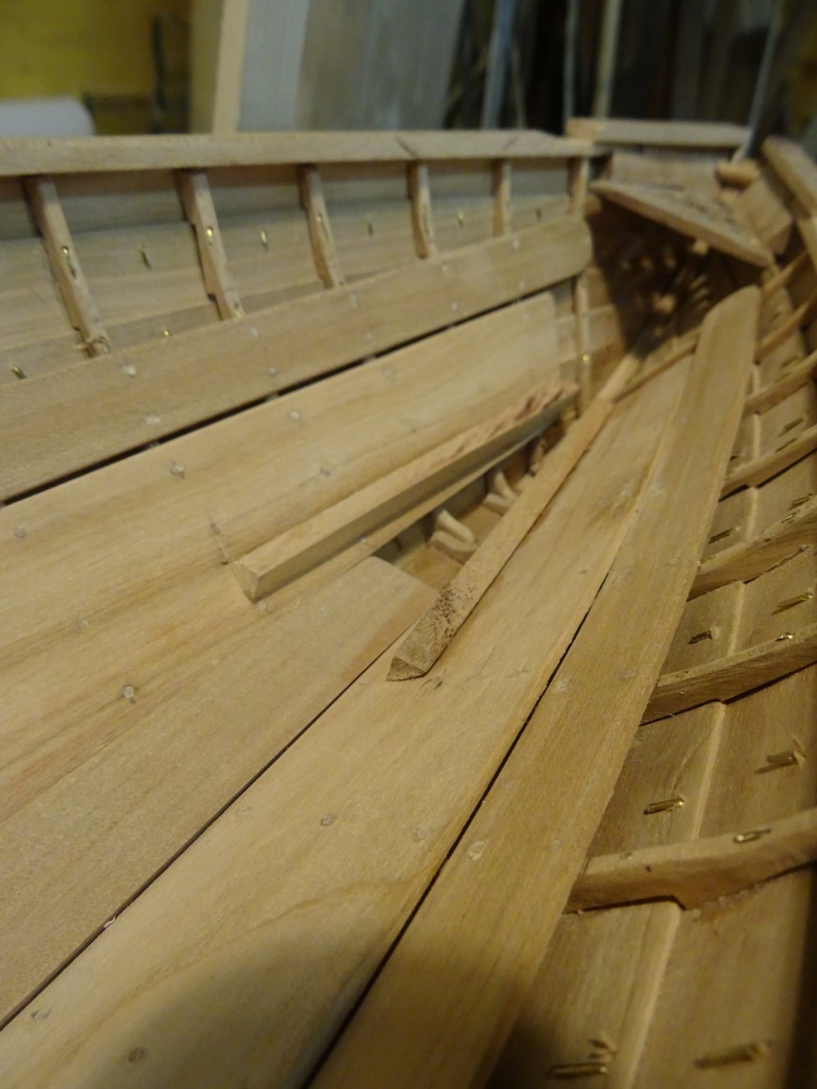
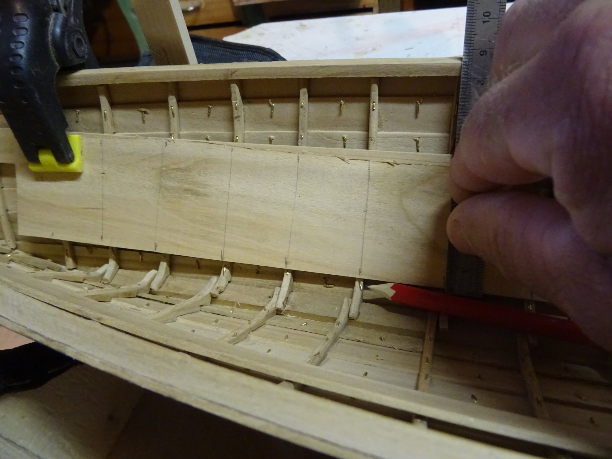
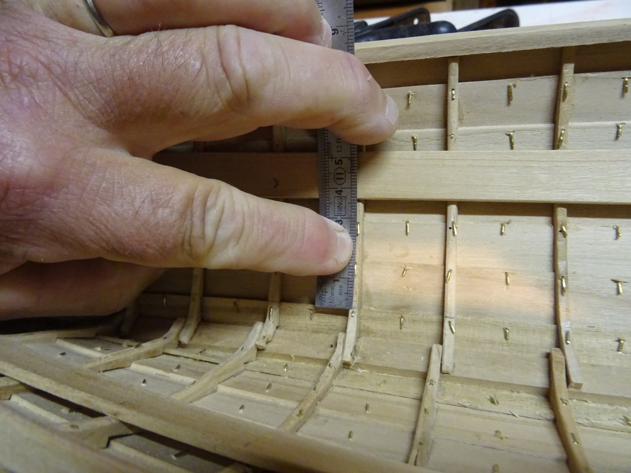
The hull planking of whale boats was made of thin cedar planks and was therefore very fragile. In the heat of the action of harpooning a whale it would be possible that the crew punched holes in the hull with their feet. To protect the hull planks between the bottom board and the thwart rising a wide stringer is placed to protect the hull.
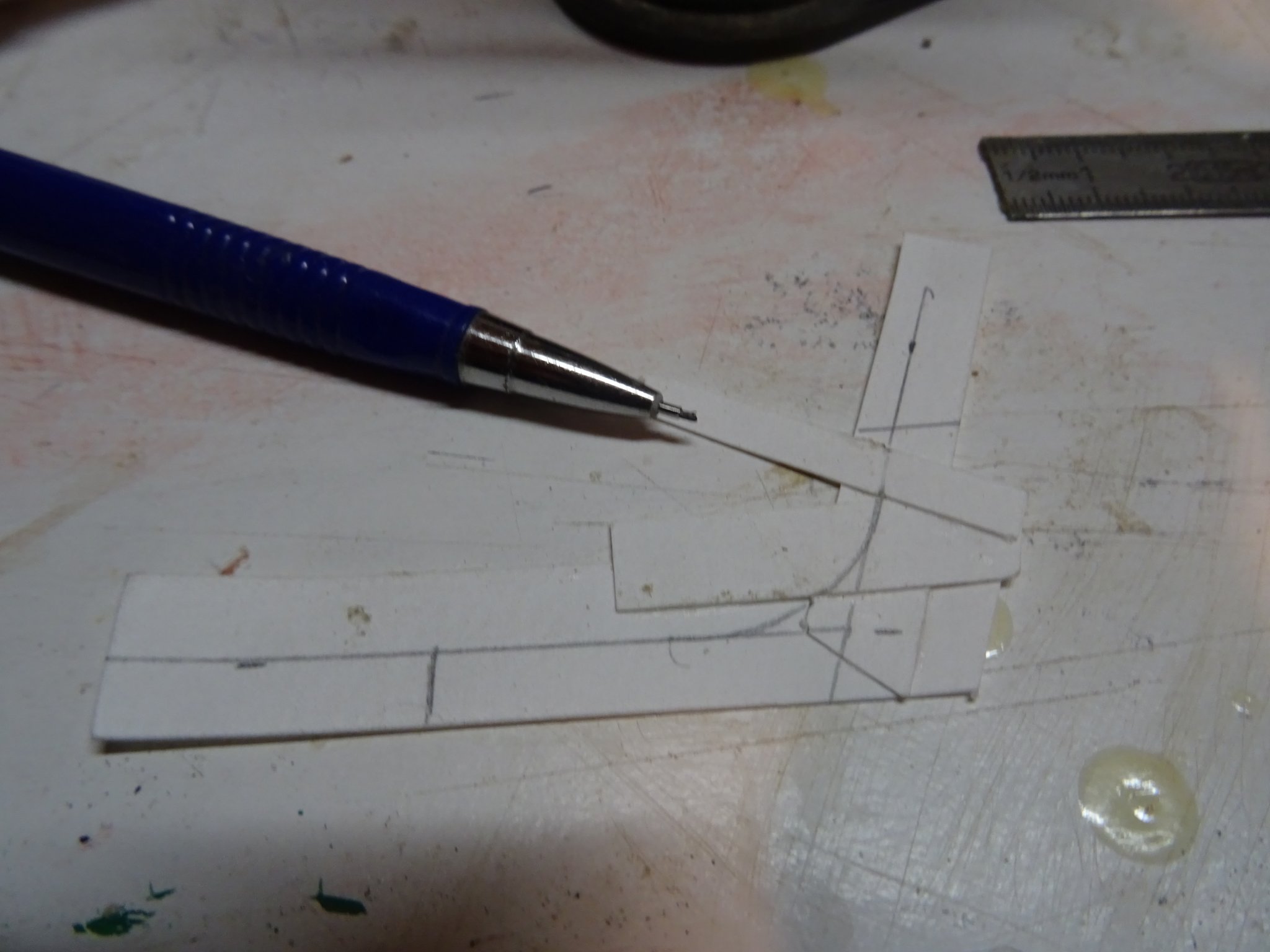
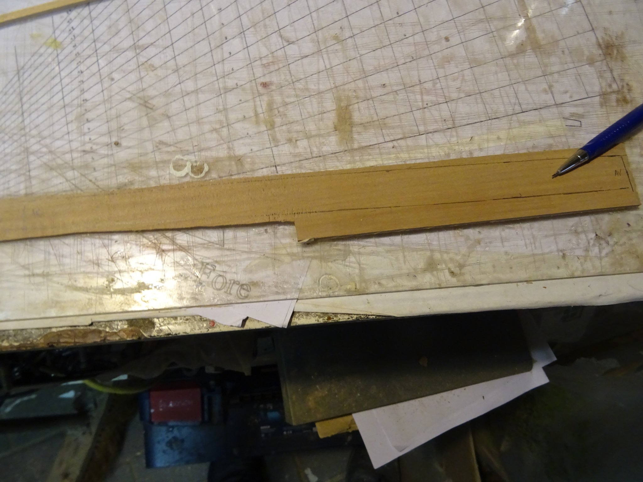
To determine the shape of that wide stringer, I start with marking the ribs on the plank. I mark also the bottom side of the stringer.
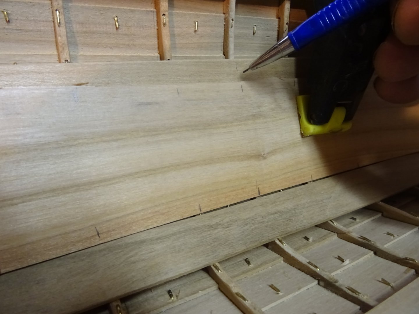

Then I measure the widths of the stringer on each rib, bring them over to the plank and saw the stringer.

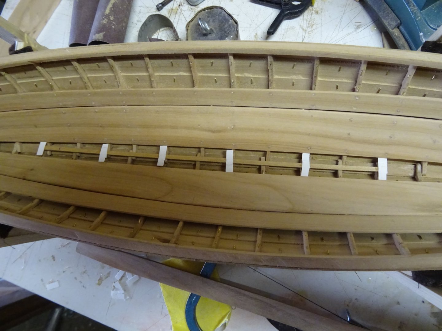
Gluing the stringer into position.

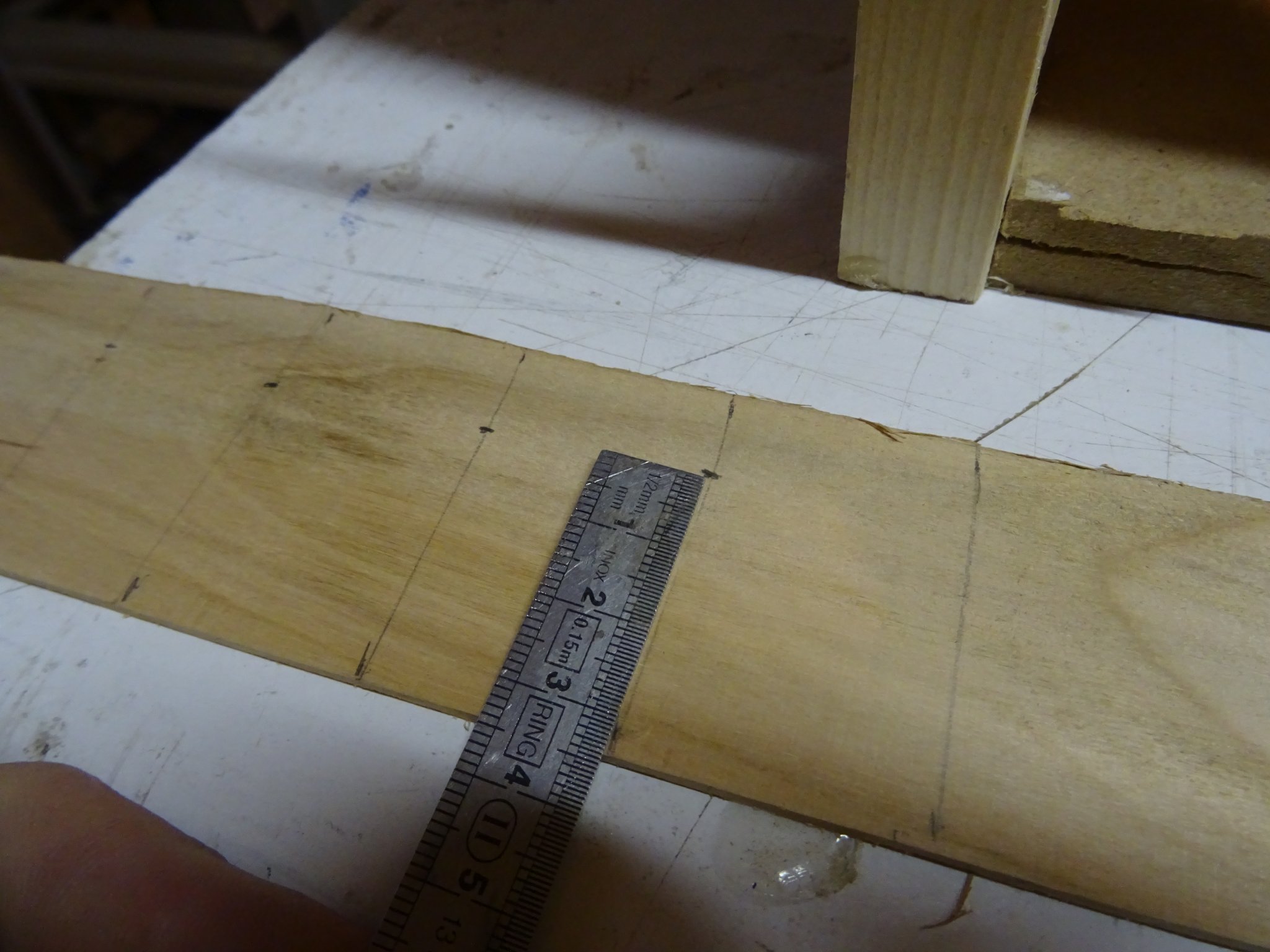
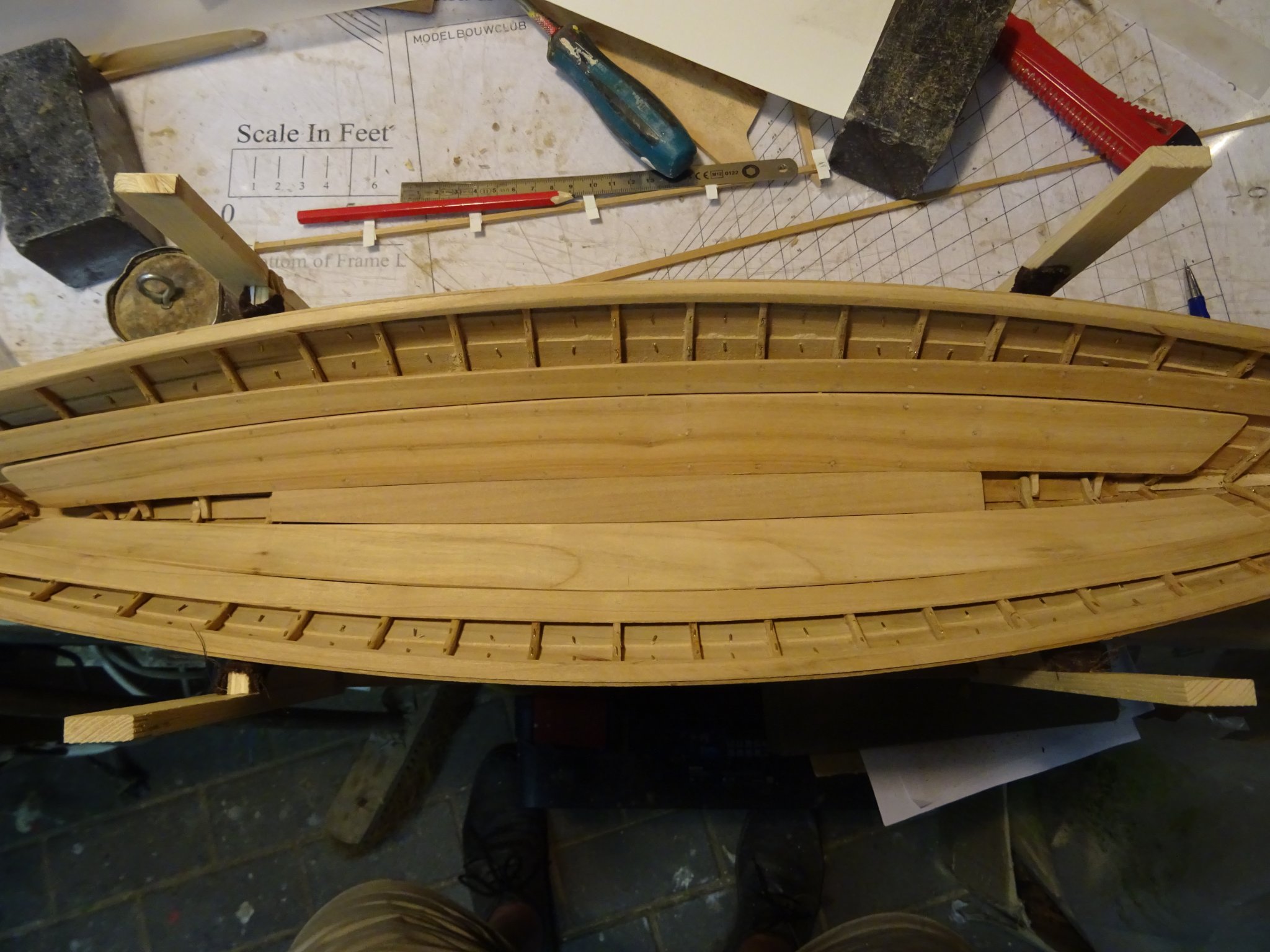
Between the two stringers lays a bottom board.
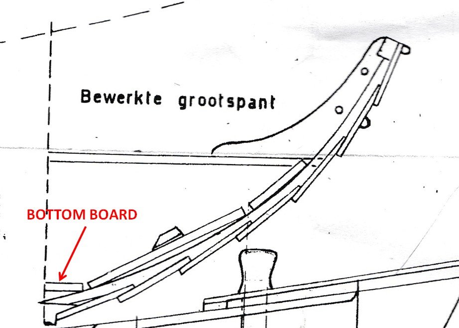
I determine the shape of that bottom board by laying a straight lath on the ribs on the bottom of the boat and marking the width of the board by gluing stiff paper strips at the height of some ribs.
Taking over the bottom board shape on a plank.


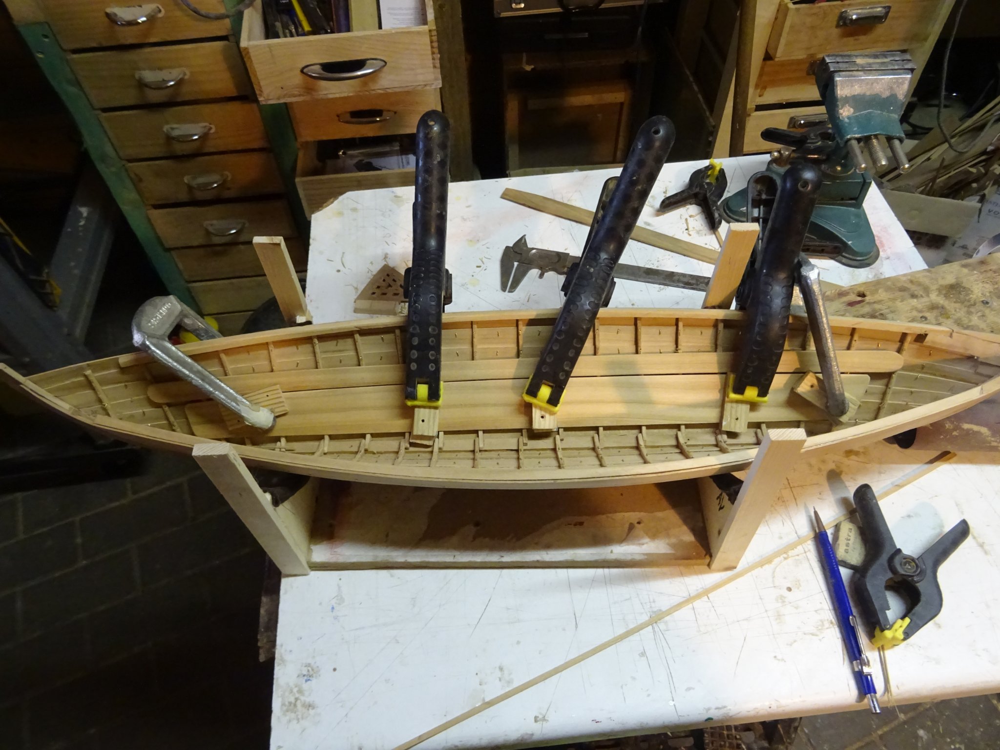
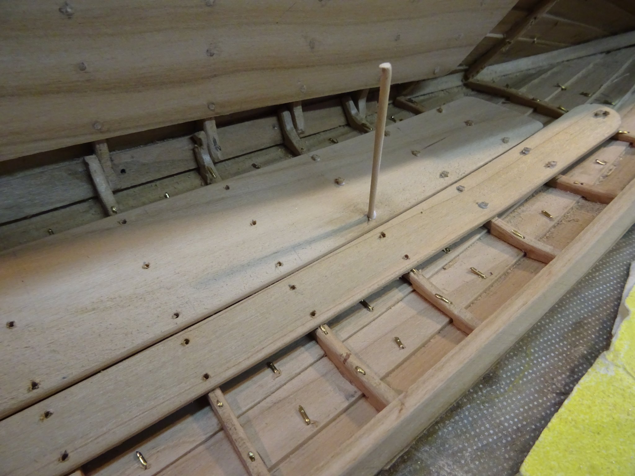
The bottom board resting in its place.

Finally I tree nail the thwart risings and the stringers with bamboo dowels.

Thank you very much for reading this log and for your likes.
Till next week!
-
That mizzen sail is very nicely done, Patrick.
Wishing you and your wife (and the cat) a speedy recovery.
- Baker and Edwardkenway
-
2
-


HMS TRITON 1773 de Jorge Diaz O - FINISHED - 1/48 - modelo completo
in Build Logs for the Full Hull Version of HMS TRITON
Posted
Also Feliz navidad, Jorge.