HOLIDAY DONATION DRIVE - SUPPORT MSW - DO YOUR PART TO KEEP THIS GREAT FORUM GOING! (Only 72 donations so far out of 49,000 members - Can we at least get 100? C'mon guys!)
×


Chuck
-
Posts
9,672 -
Joined
-
Last visited
Content Type
Profiles
Forums
Gallery
Events
Everything posted by Chuck
-
 Very nicely done Jim. And Chris that is a lovely design and subject for a kit. It should be a very successful seller. Chuck
- 80 replies
-
- 13
-

-
- Grecian
- Vanguard Models
- (and 3 more)
-
I agree Greg. I have always been tempted to do that on my models. Maybe I shall on Speedwell since there are so few guns. and another...with the same red painted treatment.
-
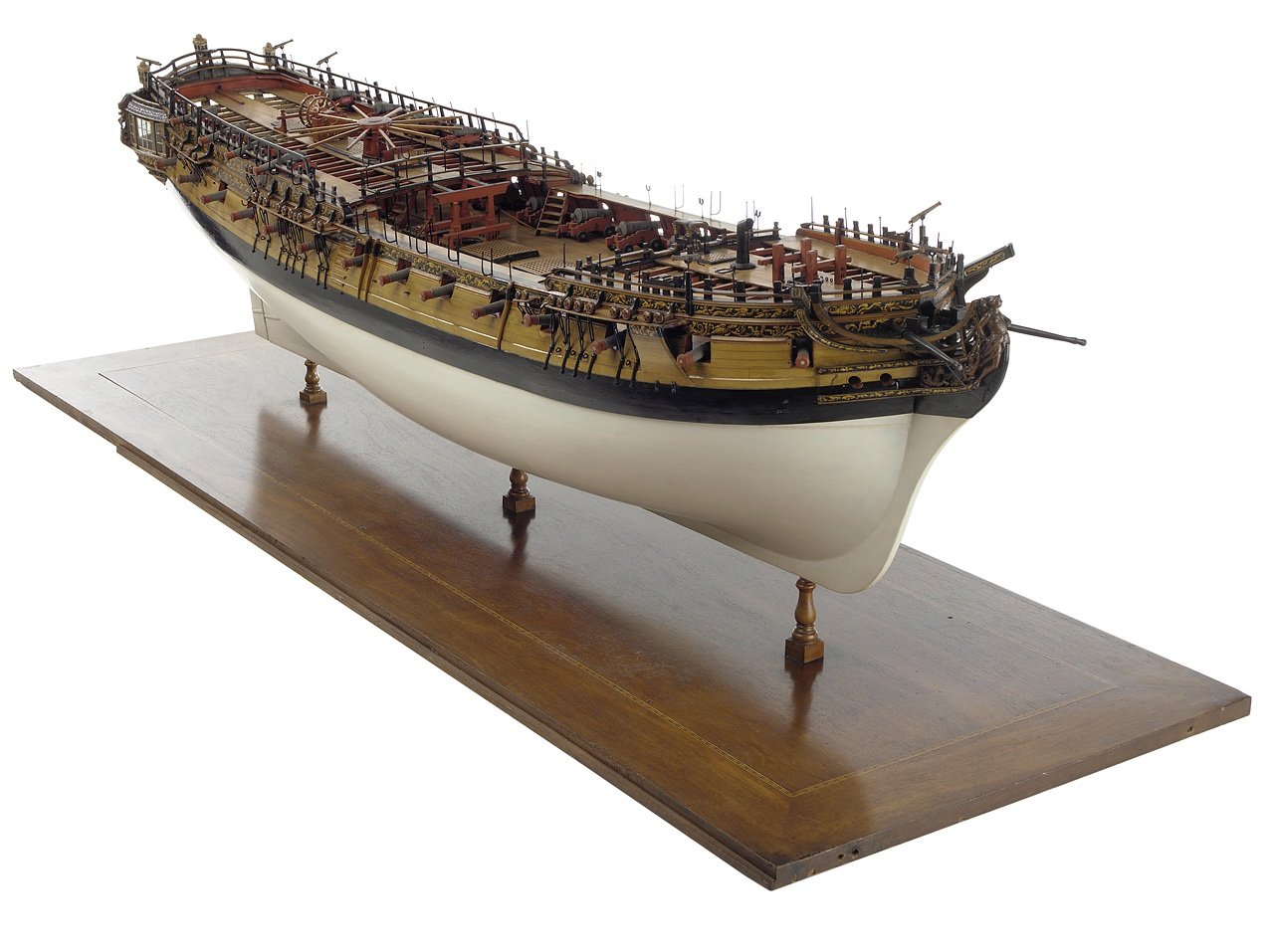
There are a bunch of contemporary models with guns run out. But they are hard to find. But they are out there. I present Amazon as a great example. This is a model that was built at a high level of detail and craftsmanship. Not all contemporary models are. So this is a superb example to use. one thing I am struck by is how much the guns protrude from the hull. This helps clear them from rigging and such. This detail is almost always understated with kits. The supplied cannon can not be run out as far as they should be. The reason why…because the supplied carriages are designed incorrectly. in addition they are centered but slightly lower in each port as you can see. But keep in mind many of the guns can and should be adjusted because they shifted on their carriages over time. Had the museum done this before taking the photos the may have appeared slightly higher in their ports. Just like with our models…the guns will sometimes shift on the carriage and the entire carriage may shift. So look carefully at this photo to see those which need some care and adjustment.
-
Great start at raising frames Mike.
-
I have to plank everything above the wales because that is not historically accurate at all. But yes I did think about also planking one side in its entirety. But I may just push forward with the interior work and not do that. There will be so much other stuff to do and if I fully planked one side I may never get done with this model. Although its going a lot faster than I thought it would. For me anyway as I consider myself a really slow builder/designer.
-
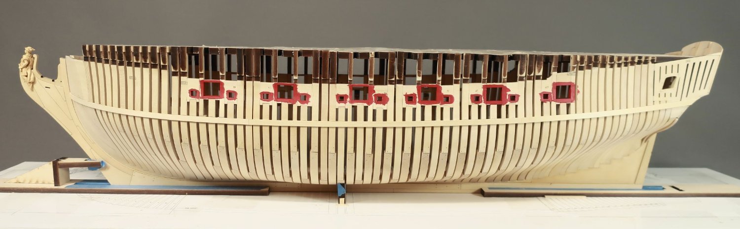
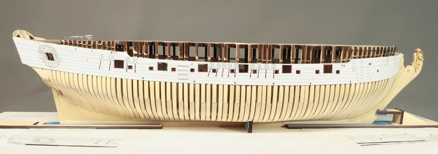
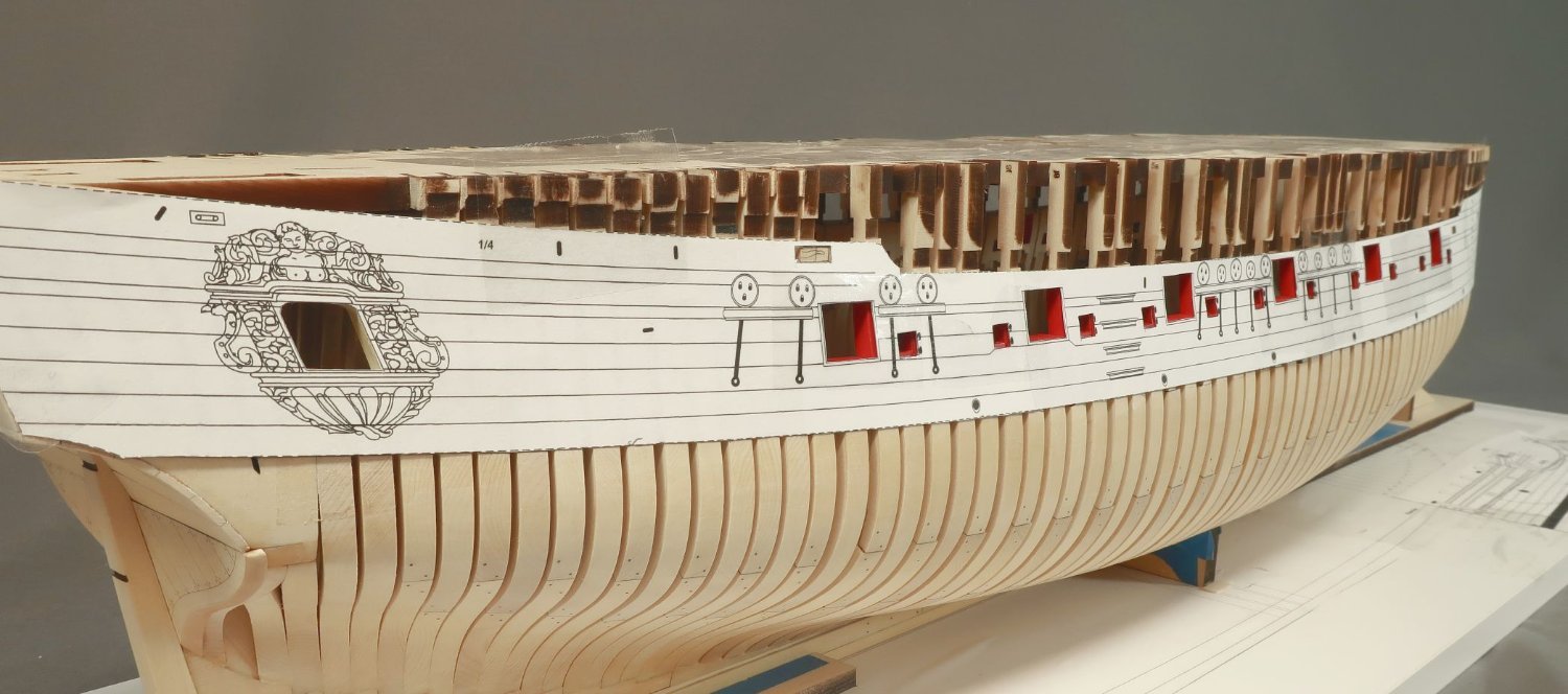
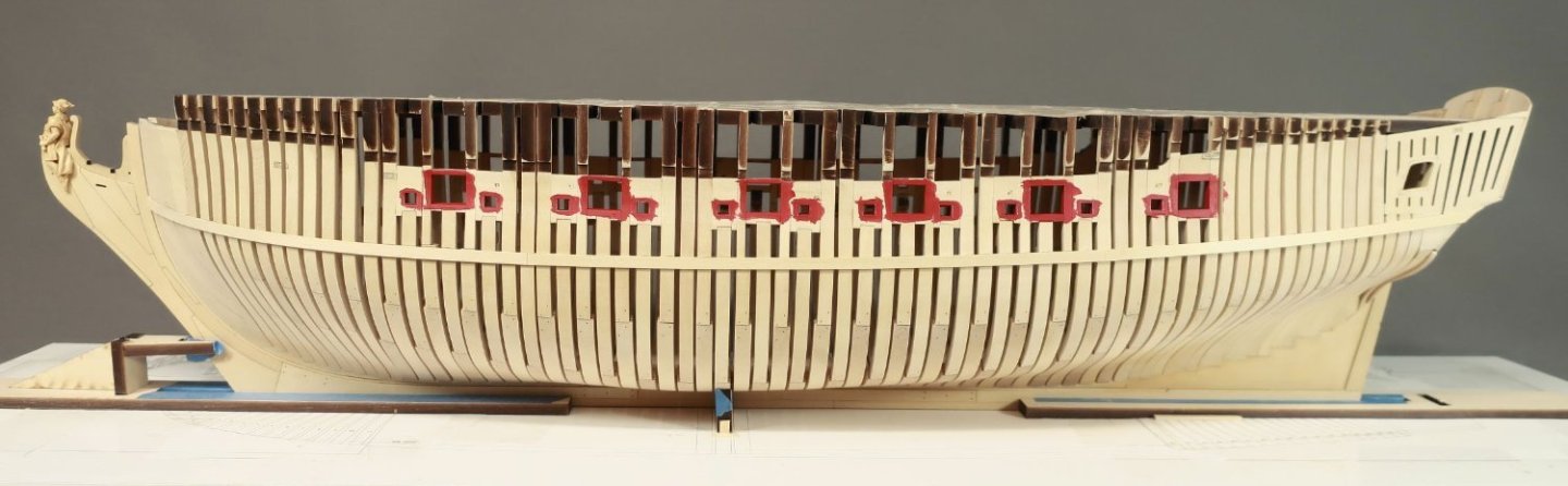
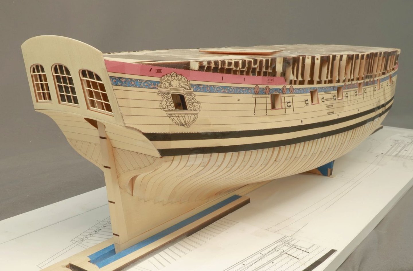
I finished the first layer for the wales. Basically I added two more strakes below the first that was added. I show this image because its the first that gives you a good indication of what the hull will eventually look like. This is as low as the planking will reach on the hull. Everything you see below the wales is left unplanked and these frames will remain visible. I do love a fully planked hull though. Its my preference actually. But like everyone else, I would be crazy to cover up all of that hard work with the frames. I will add two more strakes now above the wales. They are also 7/32" wide. Then it will be time to remove all of the top jigs. Yippeee!!! Chuck

-
Thanks Greg....I am hopeful that with 5 strakes carefully glued to each frame it wont be an issue. But that is good advice. Chuck
-
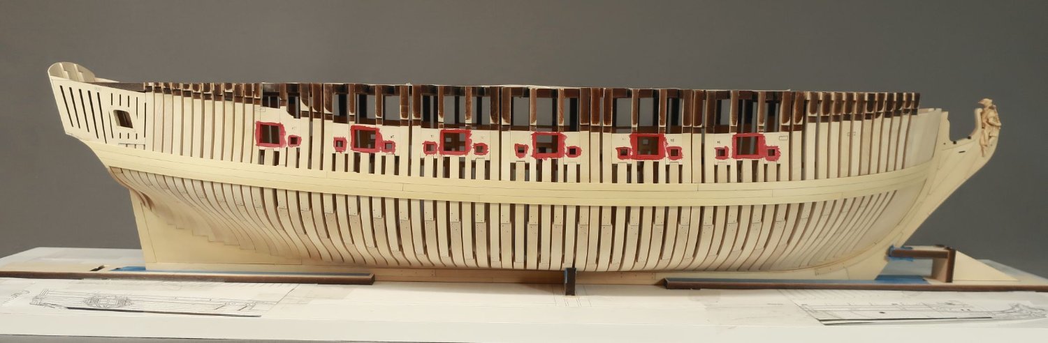
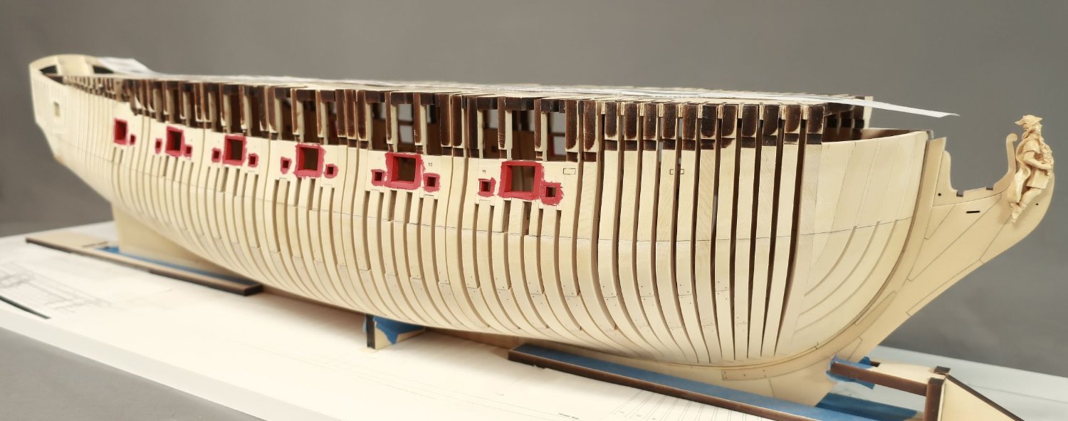
The first thing that needs to be done in preparation for planking is to paint the port openings. It is much easier to do so now and those familiar with all of my Syren projects will recognize this step. I am using the same Crimson Acrylic red for this model that I use for all of them. One note however, rather than just start painting, this model has many laser cut sweep ports. The insides of the sweep ports have laser char on them. You really cant successfully just paint over that. The red wont cover it and will appear too dark. You dont want to sand it off. That would be bad. It would change the precision shape of those port openings. Instead of sanding, I painted the insides of the sweep ports with a very light tan first. This will cover the char without compromising the shape of the sweep ports. I mixed Titanium White with some brown and yellow Ochre. Once that paint dried I switched to the Crimson. One additional note....The quarter badge opening and window area was painted tan and will NOT be painted red. This will be left tan as the great cabin will remain unpainted. Once the painting was complete I taped the two templates into position on both sides of the model. This is a VERY important step. Just like when using a batten, you must view the hull at all angles. Ensure that the template is even on both sides of the hull. The bottom edge of the templates represent the top edge of the wales. You will be carefully tracing along the bottom edge of each template to mark the location for the first planking strake to be placed on the hull. Make sure the run is good and at equal height at the bow and stern both port and starboard. I forgot to mention that you should cut out all of the sweep ports and gunports from the template before taping it on the hull. In addition, cut out the fixed blocks on the templates too. You will be tracing and marking the exact locations for the fixed blocks and the sweep port covers as well as the bottom edge of the templates. We will be adding the sweep port covers to the hull soon so we can plank around them. The same is true for the fixed block shells. Use a hard lead pencil so it keeps a sharp point longer. Yes the lead will leave a lighter line but it will be more precise. Use a 4H or even a 6H pencil for marking the hull. When you are done tracing these elements and the bottom edge of the templates, remove the them carefully. We will be using them again many times. Cut away any tape that hangs over the edges of the template. Dont try and remove it...the template will tear. Then store the templates safely for later use. Here is what the hull looks like after removing the templates. You can hopefully see my reference line that shows the top edge of the wales. But its hard to see the sweep port lines in the photo. Thats OK. Just know that they are there. You can see the locations of the fixed blocks. We will be adding the first strake which represents the first layer for the top of the wales. This is probably the most crucial of planking steps. So take you time with it. If the run and fit for this first plank is wrong then all of your planking will be wrong. It will be hard to recover from that. The strips are 7/32" x 3/64" Yellow cedar. I have a whole bunch of them ready to go. All have been matched for color. All three strakes for the wales are 7/32" wide. Try really hard to align the top of the strip with your reference line on the hull. Make sure you match the placement port and starboard. I wont rehash how to plank and how to bend the strips. I have done that so many times. Just refer to the tutorials and many logs on this site. Or download the respective chapters for the Cheerful or the Winchelsea. I am using a travel iron and bending and twisting as usual. The first strake or the upper wales have been completed. At least the first layer. I prefer to use two layers. You could however just use a thicker strip and complete the upper and lower strakes in one layer instead. Its up to you. But I personally prefer two layers because I think I can do a much better and cleaner job with the painting and placement. With this upper wale in place...now its time to add two more strakes of the same width and thickness below this one. It sounds easy enough, but remember to get a good tight fit against the strakes already on the hull. I am also using a #2 pencil to shade one edge of each strake to simulate the caulking. Although on the upper and lower wales its not important. Its only the first layer. I would however simulate the caulking on the middle layer of the wales because it is only one layer thick. I a referring to the butt joints only. One last very important note: When gluing these three strakes for the wales onto the hull, make sure you glue the strips to each and every frame. Its the planking that will hold the hull together when we remove the top jigs. So the frames need to be really secure to the planking. Place a drop of glue (your choice of PVA or CA) to each and every frame as you proceed. When we complete two or three strakes above the wales later, thats when we will remove the top jigs and establish the sheer properly. So thats coming up soon. If the planks arent secured to the frames it might be a disaster in the making. But maybe not. I am just a nervous Nelly.


-
Thanks Pat. I will be painting the ports red this weekend in preparation for planking the hull. Hopefully planking will begin next week.
-
That looks fantastic. Looking really good.
-
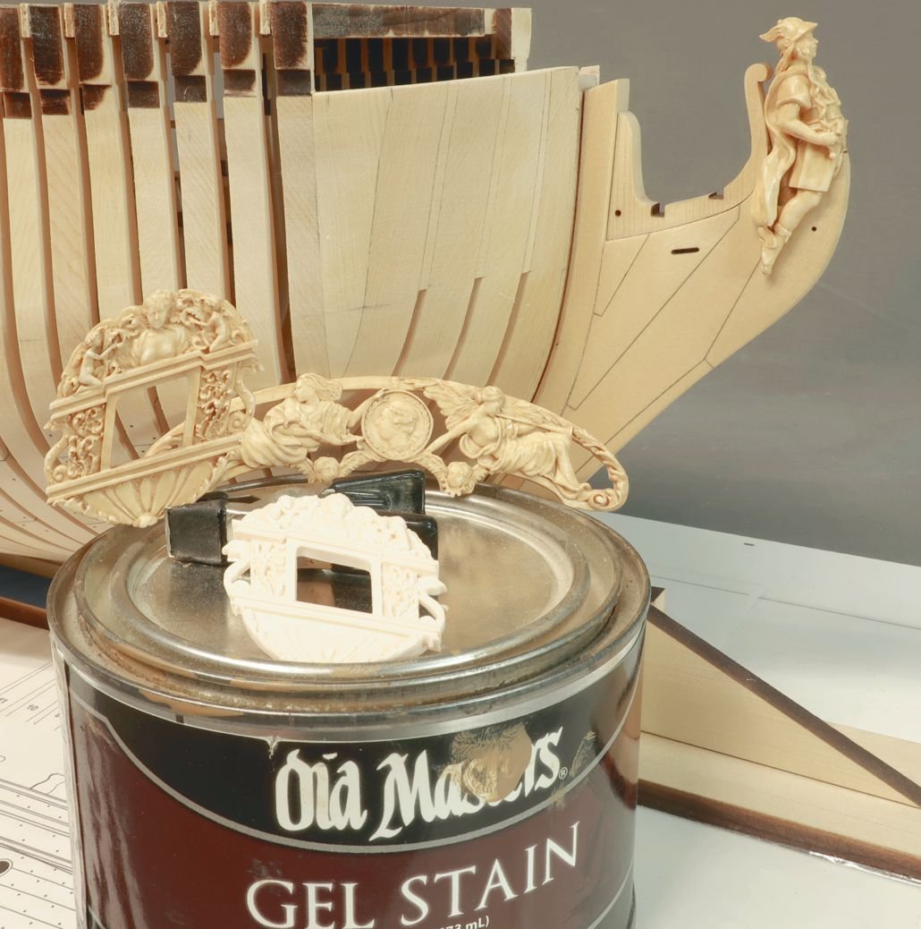
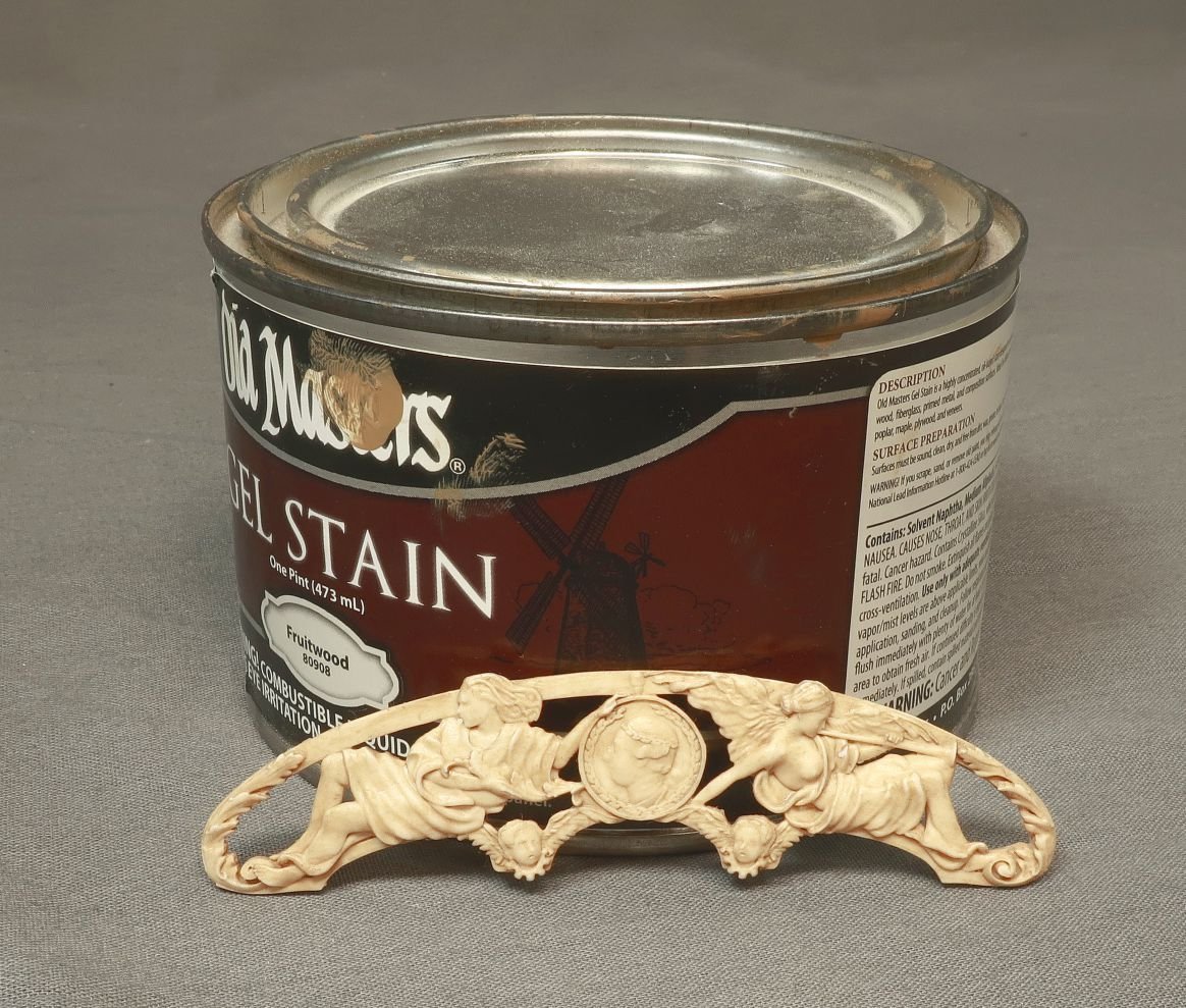
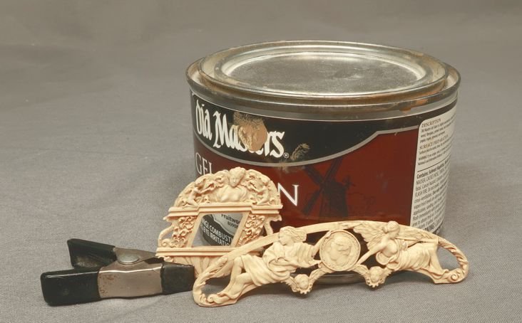
The Speedwell castings arrived. Just like the Winnie these are cast in a very light Tan. Almost white but not. This is a big help for the finishing. They were treated just like those on the Winnie. See the unfinished quarter badge on the can of gel stain? I used Old Masters gel stain. The color is Fruitwood. This is the best color for our purposes in my opinion. Just brush it on and let sit for a few minutes. The longer you leave it on the deeper and darker your color will be. Dont leave it on too long...you can always add another coat after it dries. Brush it off before it dries however with a soft clean brush. Almost buff it. The more you brush the more you will remove. This evens it all out while leaving darker bits in the deeper areas. But not overly so. The one drawback with this method is the parts tend to get shiny. But a quick spray with some dull coat after it dries does the trick. The color matches quite well as you can see. This preserves all the detail as well because unlike paint, this does not build up and obscure the small details.
-
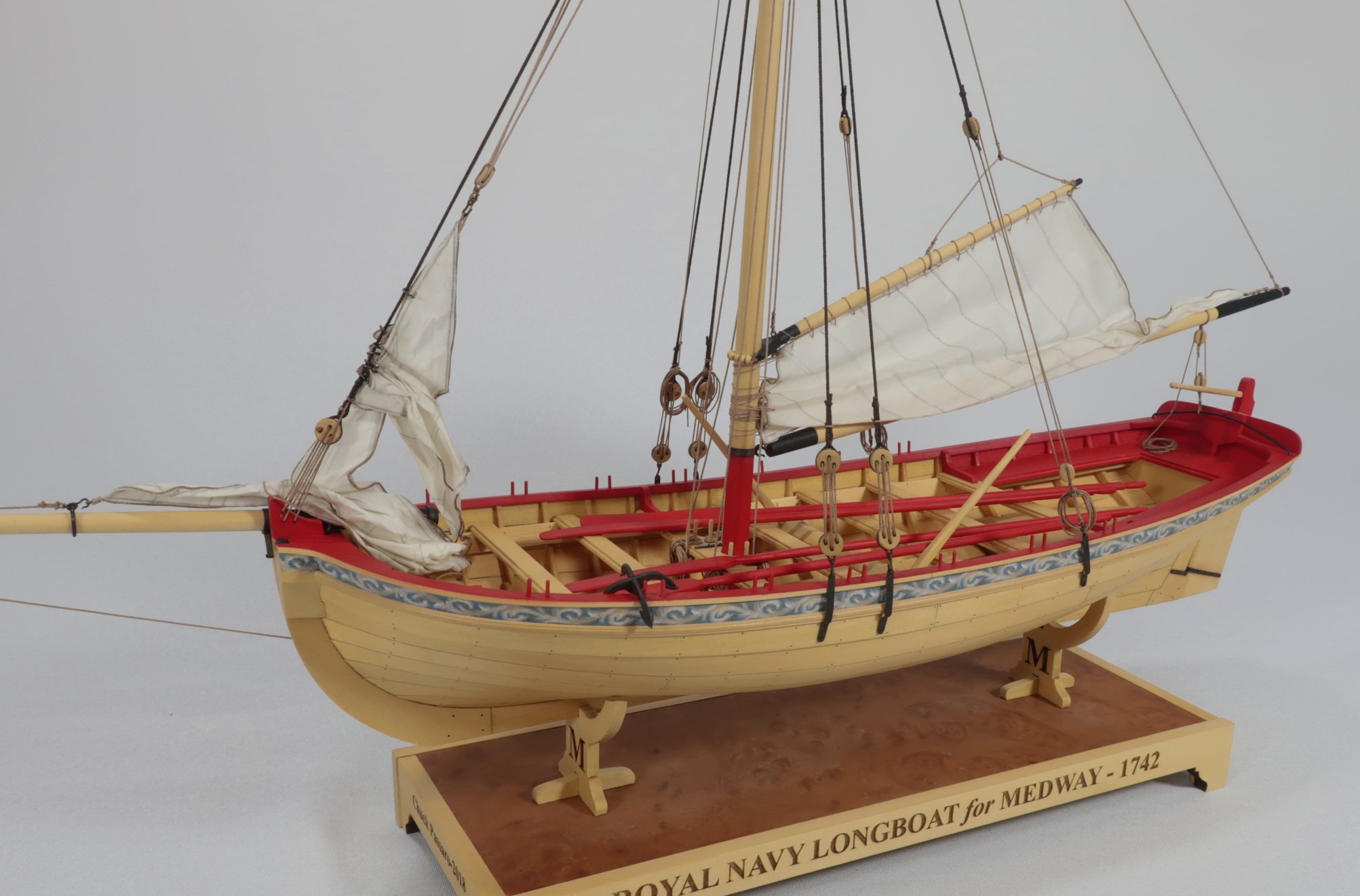
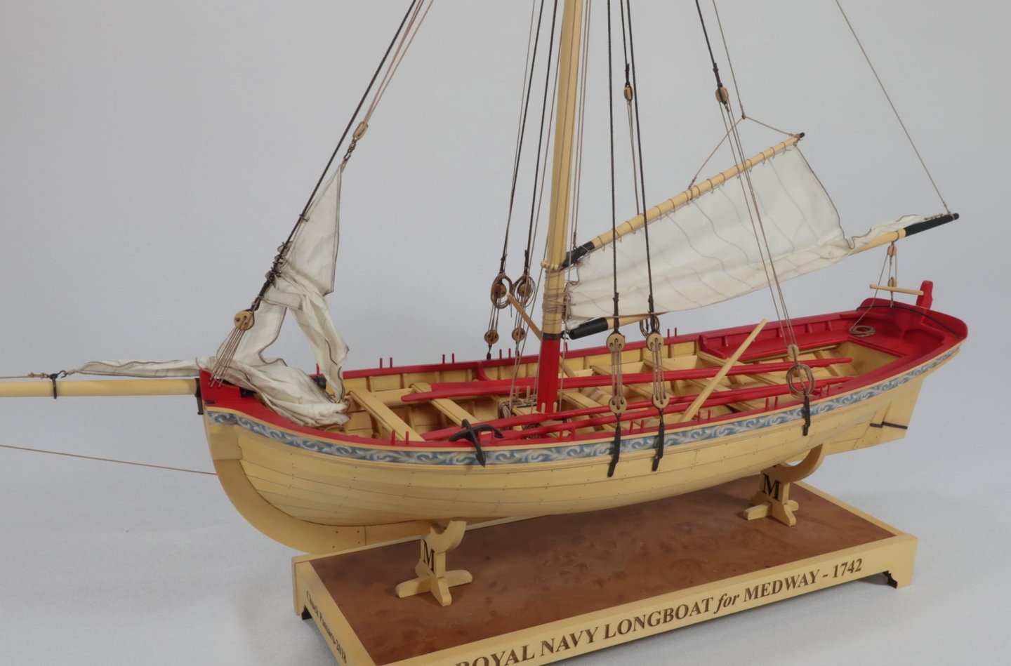
A small batch of longboat kits is now available. But they are going super fast....so ..... The masting and rigging installments will be coming really soon. I just have to bang out a whole bunch of Winnie chapter sets first. Chuck
-
Its quite possible, and its only a guess on my part but the draftsperson possibly just never finished the draft...I have tons of those laying around my shop...LOL But they look like the start of deadeyes to me. Weird place for them in the back row though. Note the different straps and not chainplates. There are a lot of unusual details on that draft....considering that it is the fcastle? A capstan on deck...and rigging blocks on the channels using chainplates. That is a first for me. Chuck
-
I have all the parts laser cut for a small run of kits and will be putting them together for purchase this week. I cannot reserve them though before you ask. First come first serve whenever I finish them up. I have far more folks who wishto reserve a kit than actual kits in this run so it wouldnt be fair to pick. I just reopened the store and I am getting clobbered. So it may be towards the end of the week. Chuck
-
Its gonna be a long long while before the blocks are available. So take your time.
-
Very nicely done....that is what a planked hull should like!!
-
I really dont know its chemical makeup...I am keeping the commercial name close to the vest for now. Never bothered to read the msds sheets. Sorry. Too much competition out there. The moment I tell folks you will see just as many kit mfgs using it like they now do with polyback...or laserboard. A guys got to have a leg up on the competition these days. Chuck
-
Thats why I havent used that Wefalck. Those fumes are deadly. My shop and laser are well ventilated but it is a small space. The stuff I am using is not harmful at all. But yes it too has an unpleasant odor. But its harmless. The thicknesses available are limited however. So I must get creative trying to cut the proper size blanks for making blocks. I have my wood provider trying an experiment right now to see if he can thickness it to the many variations in thickness I normally would need. I have my fingers crossed. If it fails however, I will still use this material for making many ship model parts...like the windows for speedwell. Its very strong and allows me to go very thin without fear of them being too fragile. I do have a fallback however to make dark brown or black deadeyes. Not Ebony but just using blackened stabilized hornbeam instead. The issue with that is of course availability. It all comes from Russia and the Ukraine or Estonia and takes forever to to get shipments. Its very expensive and not a reliable on-demand supply method. So I am seeking out suppliers more local. Should anyone know of anyone not in the EU and preferably in the USA or Canada that sells black hornbeam, please let me know. Its doesnt have the strength and wont be able to go as small as with the "plastic Syrenite" material, but I could always use the thinner sheets available for the smaller blocks. Its the larger sizes that are problematic....I can buy 1/4" thick stuff but it does not come in 3/16" or 5/32" or 7/32" thicknesses...so I would need to add many different steps to laser cut strips that thickness. For example I need 3/16" x 3/32" strips for one of my blocks. I would first need to laser cut strips to 3/16" x 1/4" from the 1/4" sheets and then redesign my files to use those to make blocks 3/32" thick. Its just a lot of added steps and a lot more laser time than I would like. Using Black Hornbeam eliminates these steps. I just take a 3/16" thick sheet of black hornbeam and rip a bunch of 3/32" strips and I am done. The Syrenite stuff only comes in 48" x 48" sheets or 4 x 8 sheets as well. So handling and cutting smaller sheets that fit my laser cutter are a pain with the thicker stuff. But the thin stuff cuts easy enough with a blade and a snap... So there are a few kinks to work out. Chuck
-
I believe that model is misidentified. It looks nothing like the class its supposed to be. I think its much earlier as well. But I dont think it is the actual endymion.
-
Yes it is. Absolutely gorgeous.
-
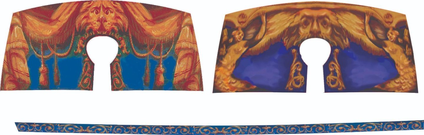
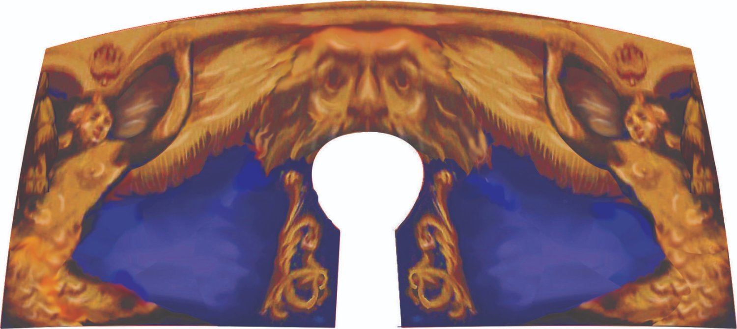
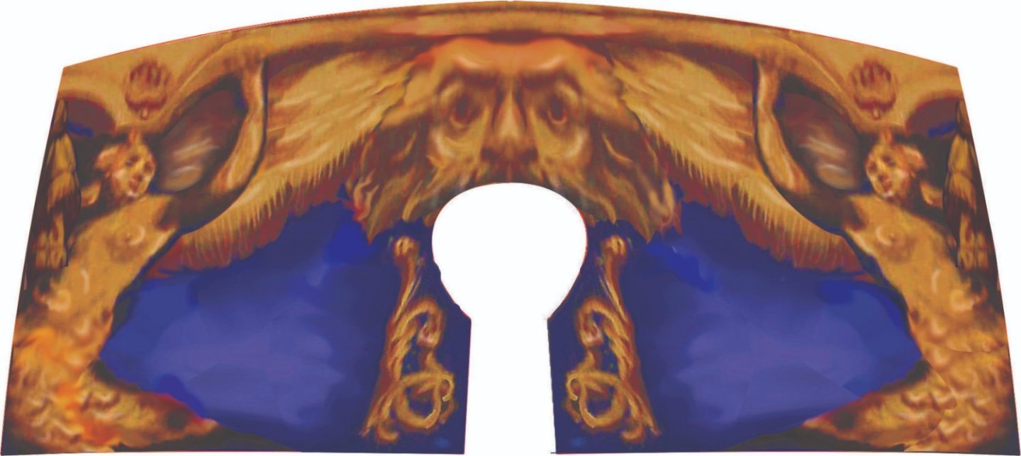
The color is off on the left version...too orange for me and wont go with Speedwell. I may have t adjust the color on that left version but it takes forever to do.
-
LOL...I suppose I could have put those two Syrens in a pants suit for the more conservative model builders out there. But I think it best to stick with the typical imagery used during the time period. I chose the syrens for an obvious reason. If I can sneak one into a project I am working on I wont pass up the opportunity. And by the way...choosing a frieze of the best color and shape is not an easy task at all. I may yet do a third version. Its a big part of the models visual appearance. I look to find actual friezes used on Contemporary models and then adapt them to my projects and change them up. Adjusting the shapes and colors etc. The inspiration below....adapted for the Speedwell. Oneof my all time favorite contemporary models. If I could find the drafts for this I would build her in a second. Chuck
-
I made up another alternative as I wasnt sold on the color of the original I made. I think this one will blend in more readily with what I envision for the model. Regardless ...both with be made available and folks can choose. I wanted a darker and larger blue field which this new design gives me.