HOLIDAY DONATION DRIVE - SUPPORT MSW - DO YOUR PART TO KEEP THIS GREAT FORUM GOING! (83 donations so far out of 49,000 members - C'mon guys!)
×


michael mott
-
Posts
5,200 -
Joined
-
Last visited
Content Type
Profiles
Forums
Gallery
Events
Everything posted by michael mott
-
 Vaddoc, I would do a test with the particular type of wood that you will be using. The basic premise its to balance the moisture so when you go to glue the piece simply coat one side with a sponge to wet it apply the glue to the other and then clamp together. Michael
- 253 replies
-
- 1
-

-
- ketkch
- gaff-rigged
- (and 1 more)
-
Nothing like some public pressure, to get something done. Looks great so far Bob. Michael
-
Denis lead is so malleable you could probably just flatten a lead weight with a hammer on an anvil of some kind. Michael
- 956 replies
-
- 2
-
-
- andrea gail
- trawler
- (and 1 more)
-
Thanks for the clarification Ed, I have used the same technique for other applications. Michael
- 3,618 replies
-
- 1
-
-
- young america
- clipper
- (and 1 more)
-
Again it is a joy to watch your ship taking shape Ed, beautiful workmanship. In the picture with the drill cutting the port lights, I wondered about break out on the inside, do you hold a block there to prevent the wood from splitting away as it breaks through or is that not an issue because you are using a brad point drill or the wood just doesn't do that in this case? Michael
- 3,618 replies
-
- 1
-
-
- young america
- clipper
- (and 1 more)
-
This is the unofficial motto of scratch building Congratulations on the work so far. Regarding the warped wood, Might I humbly suggest wetting the whole piece of wood by dropping it into a tub of water and washing off the present glue. wipe it dry and let it normalize or go flat again, it will either flatten by itself or might need a book or two to act as a flattening aid. When it is either flat or flexible again because of the replaced moisture, before it dries out completely re-glue and re-clamp and leave until completely dry. Michael
- 253 replies
-
- 1
-
-
- ketkch
- gaff-rigged
- (and 1 more)
-
Mark that looks like a very good solution. Michael
-
I ran into that exact wording at a lot of places, Shippers Supply carry it still in a couple of widths . Your friezes turned out well. Michael
-
Mark I was thinking about this sort of thing and this michael
-
Hi Mark, I wonder if the etching process is the best choice? I seem to recall that Doris used the fine Fimo type modelling clay to form the insignia on her cannons, I cannot remember the post but she did do some tutorials on some of this very small detail stuff. I am assuming here(one of my recent failings ) that this is for the mould. I will see if i can find it, I could also be completely out to lunch on this one. And thank you for the kudos regarding the machining. Michael
-
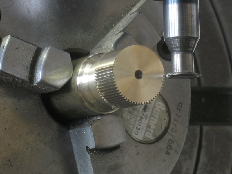
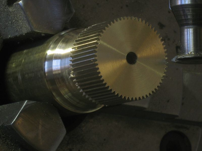
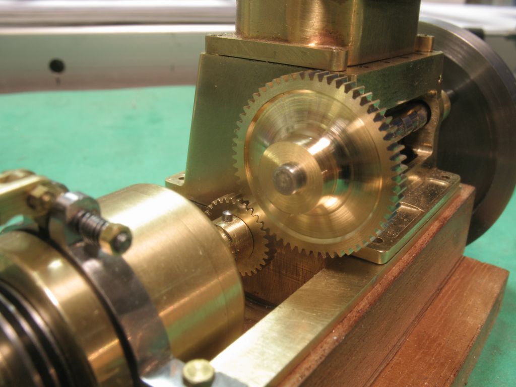
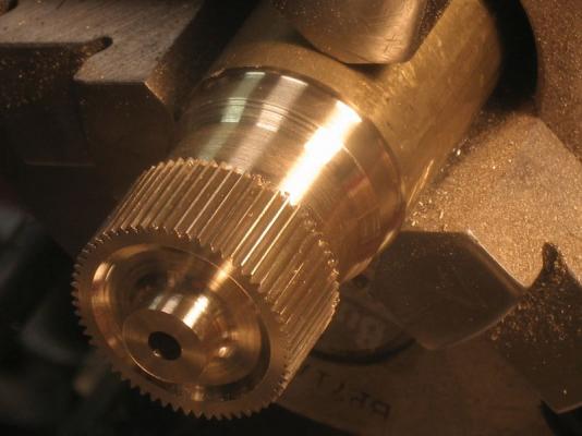
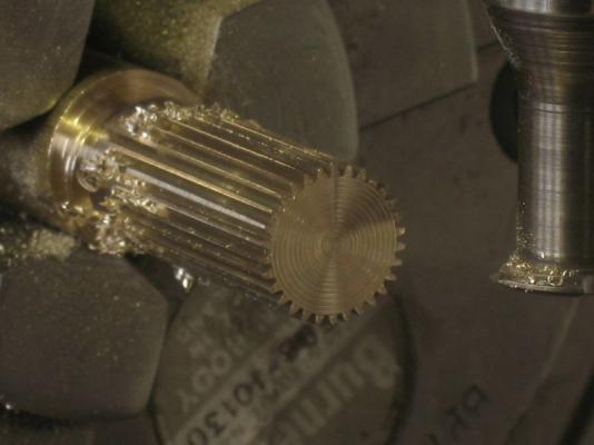
Ed, thank you, your comment means a great deal to me. this evening I am having a hard time wiping the silly grin off my face. Beginning cuts Half a day later the last tooth cut Back to the lathe for some rough shaping I ground up a bit of a form tool to get the curved recess better. After parting it off I slipped it onto the camshaft . It is actually on the shaft backwards I have to set it up in a fixture on the four jaw chuck now and machine the eccentric cam for the water pump then it can be flipped to finish the front side. It did mesh nicely though even without any clean up yet, Michael


-
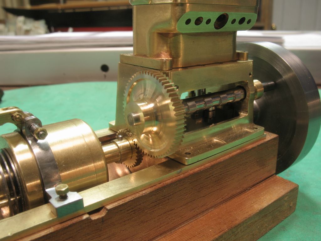
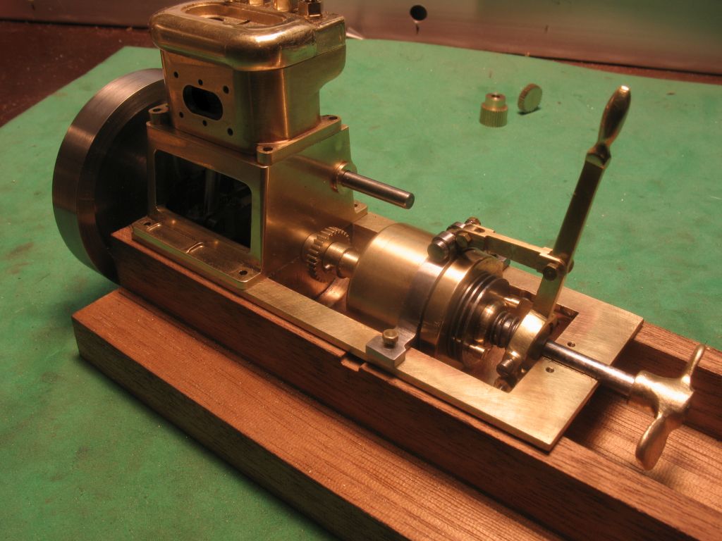
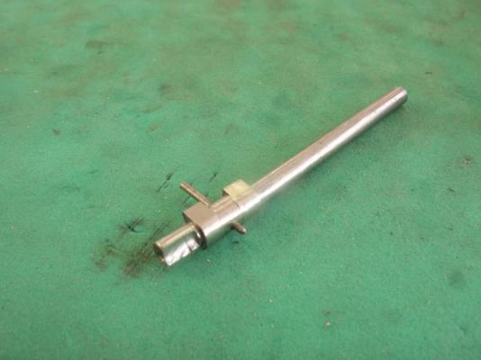
Elia the short answer is Yes. I began with the base external Dimensions of the Engine, as noted in the Buffalo catalogue. determined the bore and stroke based on a scaled version of original core dimensions such as the diameters and lengths etc. Some dimensions are absolutely critical, Gear meshing , piston fits shaft diameters and so on. I do have leeway over many ancillary dimensions though. for instance the outside diameter of the hub for the 30 tooth gear, I drew it at .250" I think the final finished dimension was .249" is doesn't matter and without miking the diameter it is impossible to see. it could just have easily been .235" Without actually having the real engine in front of me to measure, and this is a model after all I certainly have taken dimensional liberties as well as material and design ones. I have no way of knowing some dimensions and so they are guesses, there is enough "stacking " as you say that I can make some adjustments as I go along. One of the most critical and challenging fits is going to be the smooth meshing of the gears, on the real engine the DP of the teeth is an unknown to me, I could have done more research and found out exactly no doubt but being impatient I scaled from photographs of the engine counted the number of teeth, in actuality the real gears are 64 and 32 a 2:1 ratio. I do not have a proper dividing head or gears with those numbers of teeth to use as masters, only a rotary table albeit a good but very large one it can measure into degrees minutes and seconds. The key information is the ratio of 2:1. The camshaft had to be clear of the con rods, and I had some general dimensions based on the catalogue and photographs Gears are really no more than a couple of discs ( Pitch Circle) that rub against each other with teeth projecting from each so as not to slip. There are tables for all the standard tooth sizes these are based on the Diametral Pitch system which is the number of teeth in the gear for each inch of pitch diameter. lots of small gears use 64 or 48 teeth per inch these are standard ones that are sold through the commercial vendors. On the engine that I am building neither of these pitches provided a pair of gears that were the correct ratio and the correct number of teeth to look scale or the correct Diameter(approx in any case ). I used the formulas to calculate from the diameters that were formed from the two circles on my drawing for the crankshaft and for the camshaft a set of gears that would give me 60 teeth and 30 teeth it worked out to 75 teeth per inch of pitch diameter. A non commercial gear size, so using another set of tables in an article in a Model Engineer magazine, developed by model engineer D. J. Unwin, I made the tool to make the cutters for the 75DP gears. Here's the rub, on paper they mesh perfectly ,I will find out soon enough if my machining tolerances are good enough for them to mesh perfectly in situ. In the (unlikely ) event that I need to make a minor adjustment I can make the camshaft bearing housing which are 3/16 diameter carrying a 1/8th inch shaft (.18725" and .125" respectively ) I can make a second set that is very slightly eccentric which would allow for the camshaft to be moved to in order to have the best meshing. This is my fall back position. I think that we always need to consider the fall back position when we are building our models because "life is." Apologies for another long winded answer, but a nice break from winding the table on the mill , only 30 teeth to go on the big gear. Michael
-
Jud, thanks, regarding the shaping, the thing is I am taking very small cuts with the tool on a fairly forgiving material for the most part. The way the tools work on the lathe is mostly the work moves and depending on the diameter and shape of the tool the cutting will usually produce a nice smooth cut. Sometimes the cutter needs to be reshaped or lubricated to get the desired result, most of this has been learned by observing what happens when one tries something. When I say that I am using the lathe or mill like a shaper, it is in the loosest way really, as you know on a shaper the tool is hinged so that on the back stroke the tool lifts and then the machine indexes over to make the next cut. My tools are fixed and so the back stroke the tool stays in the same relative position. I am making very small cuts .005 max on the first cuts and backing off as the form tool gets deeper because it is doing more work, think of the chamfer on the corner of a piece of wood, as the chamfer gets wider more material is being cut by the plane or chisel, the same thing happens with the tools on the lathe. The important thing is small cuts and keeping everything as rigid as possible. the last cuts on the gear teeth are repeated over 2 or 3 times without adjusting anything, the natural spring in the tools and materials take just that little bit extra material off in those last cuts, it is almost undetectable but it does matter for the final finish. Each tooth on the gear takes a minimum of 15 cuts back and forth before moving on to the next tooth. it is a slow tedious process but satisfying because I can make what I need. I am 15 teeth into the 60 tooth gear at the moment and have to take little breaks to keep my sanity, and concentration level up, it is so easy to get lulled into a rhythm that causes a lack of attention and wham, a missed action or an additional one that can spell disaster, like this. Just some thoughts about the way I work. And again thanks for the likes Michael
-
Yes....... A Swiss Watch! Thanks everyone for your compliments Michael
-
Hi Jack I just went through your entire build, you had a tough bit there with the planking but it all worked out well in the end, your patience paid off. It is a very nice looking model, and once you have this one under your belt I am sure that you will dive right into the next one. There is something special about these small boats that I don't feel with the big ships. I think it has something to do with the immediacy of the human element and that they are much closer to the water and hence the action of nature. Michael
- 41 replies
-
- 1
-
-
- 18th century longboat
- model shipways
- (and 1 more)
-
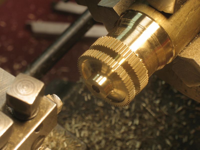
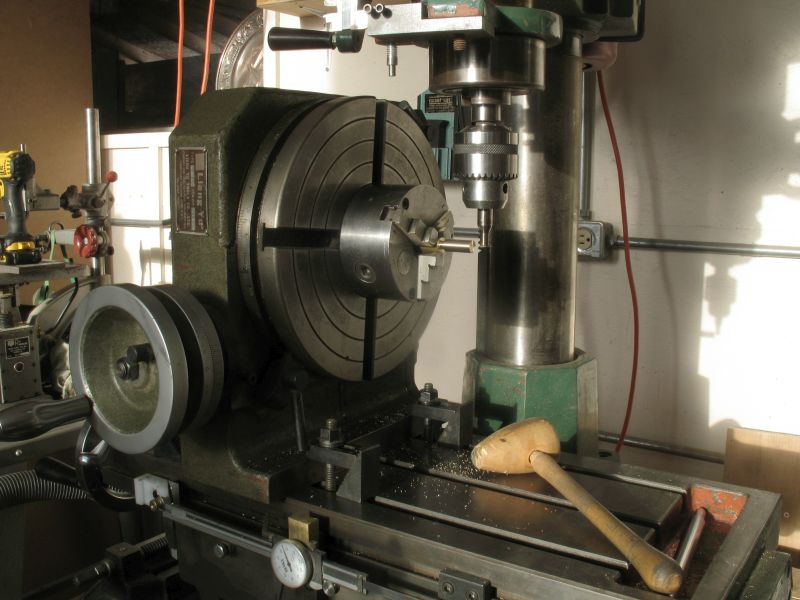
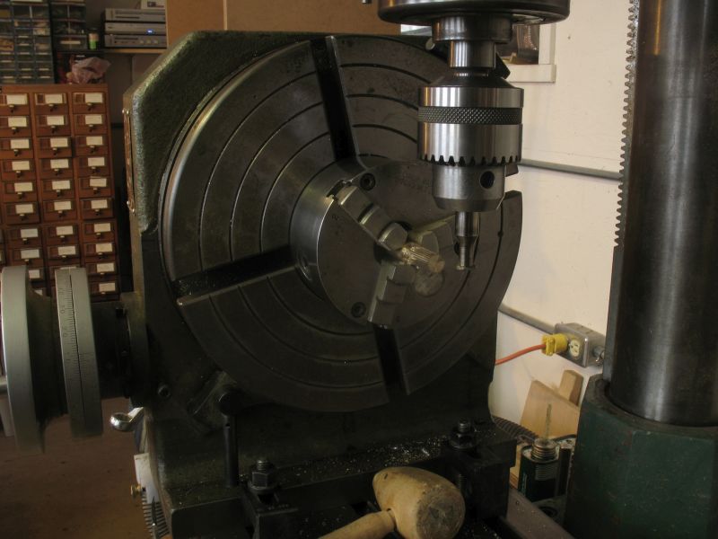
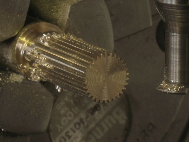
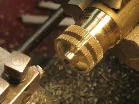
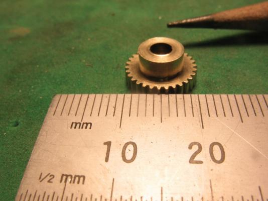
Row, Denis, Jeff, Carl, Jack, that you all so much for the encouraging remarks, they take the edge of these types of screw ups. Thanks to all who are following along and noting it with the like button. Today was a much better day nippy (-32 this morning) but better. I went back to square one with the tooling and reset the rotary table in the vertical position, and spent the time needed to get the chuck properly centered on the table with the dial indicator. I turned down some new stock to the .422" diameter the advantage to using the mill table and rotary is far greater accuracy can be achieved. the depth of tooth cut can also be very accurately regulated the depth is .031" and I fixed the quill on the mill so that it could not rotate and unplugged the mill, then worked the table in the same manner as the compound slide on the lathe, in other words I used the mill like a shaper this time. I prefer the way the material finish occurs with the shaping cut versus the rotating cut. The indexing was simply a matter of rotating the table in increments of 12 degrees. Once the shaping of the teeth was completed the chuck went back onto the lathe to finish the other operations , drilling and boring to 1/8th and cutting the hub for pinning. It cleaned up nicely and is now waiting for its big brother, on the camshaft, but i have to make a new cutter first. Michael


-
Mike She certainly can take the weather. When I read your notes about scale effects and the issue of having the model sail in a scale fashion, I was reminded that when Judy and me did the ballast test on the pilot cutter earlier this summer, there was a stability that that I liked about the way the water acted on the hull. What I am trying to say is that even with some ballast missing the hull moves gracefully and did not bob about like a model. I know that sounds funny but I think you know what I mean. And I want to say that your woodwork looks top notch. Michael
-
Hi Vaddoc I will also be following along your choice of boat appeals to me for obvious reasons. Michael
-
Nils, you are doing an amazing job with the rigging and sails I had no real idea of how much detail can be incorporated into the rigging and spars. Michael
-
Those barrels look just like they will add the right amount of color and fun detail to this Denis, I would agree you will need to lash them down somehow, I think half a dozen 45 gallon drums of stuff rolling about on a heaving deck could cause a few skittles to get bowled over. Michael
- 956 replies
-
- 2
-
-
- andrea gail
- trawler
- (and 1 more)
-
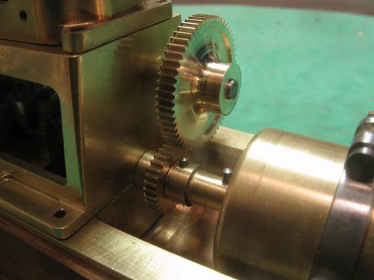
Math is definitely not my strong point it seems. yesterday I spent a fair bit of time cutting the (30tooth) gear and as I came to the last tooth I could see that something was awry because I cut a half tooth. Thinking I had skipped a tooth on the indexing I counted the teeth 32.5 noooooooooooo counted again 32.5. I used a felt marker and recounted the big (60tooth) gear on the lathe 65 ..... 65!! . Somehow I had got it into my head that the big gear was a 60 tooth gear? hearsay ...myth, a wild guess I don't know.... what is the old saying about assumptions? So one step forwards 5 steps back, a rethink of what to do next. All I know is that it involves setting up the rotary table in the vertical position on the mill which is what I ought to have done in the first place. It is just such a pain in the neck to do, because it is a very heavy bit of tooling, and really a bit too big for using as a dividing head, that is why i was so pleased that the gear on the lathe was a (60 Tooth one)perfect one for the job. Oh Well....tis a good job that I am not getting paid for this and it is just my education that I am dealing with.... don't make assumptions you would think that I would have learned that one by now. Lesson learned! to be continued Michael
-
Shenandoah by Leo-zd - 1:200
michael mott replied to Leo-zd's topic in - Build logs for subjects built 1851 - 1900
Very nice indeed! I like these small cutters. I am looking forward to seeing this one progress. michael