michael mott
-
Posts
5,200 -
Joined
-
Last visited
Content Type
Profiles
Forums
Gallery
Events
Everything posted by michael mott
-
 the Framing showed us the sweet lines of her hull and now the planking just exemplifies them even more. nice work on the planking John. Michael
 -
Steve I have every confidence that it will work perfectly. and thanks for the compliment. michael
-
Bob the privilege is mine having the luxury of good health, time and materials to be able to follow my hobby. There are those much less fortunate because of many factors beyond their control, where life and the environment intervenes. Bob,Yes I will be going with straight brass for this engine. There was very little solder left, it was only the small sections of the wall on either side, the soldering iron was clean and held on the end of the composite until the heat melted that connection then the small bit of spring that was in the tweezers was enough to pop them apart. I did not take a picture when doing the first one I will for the second. Thanks Pete. And to all who added likes. Michael
-
Pete the frames look great, how thick is the basswood and what are you using to cut them out? Michael
- 112 replies
-
- 1
-

-
- buzzards bay
- herreshoff
- (and 1 more)
-
Jud, Carl Mark, Jeff thanks for stopping by and your kind comments. Carl I did not make shell bearings for the crankcase (yet) I thought that since the main body of the lower crank case was already brass that i would not bother, I do not think that the engine will get enough run time to cause any problems, I could be way out in my thinking it this case but we shall see. the con rod is however aluminum so I put them in. Mark the answer is yes and no, the reason being that it depends on what I am cutting. Sometimes i would like to be able to cut just along the one edge of something as in a split collar for gripping a part to turn it. I generally adjust the height with the tool post to get it to centre, This is one of the great things about quick change tool posts. I have also been making more use of the end hand wheel on the lead screw rather than using the big handle on the carriage, which engages into the rack for moving the carriage when the lead screw is not turning. Originally I only used the lead screw when I was either cutting a thread or making long fine cuts using the power feed. I have been using it more these days because the hand wheel on the end of the lead screw is marked in .001" increments so it allows for more accurate positioning of the carriage, and seem to smooth out the motion of the carriage. This is important when making precise cuts a specific length. The other is getting the cutting tool square and knowing the exact width of the tool, and getting the cutting edge on centre. I also listen to the cut a lot, it always amazes me how much we use our ears when using tools. Thanks to all for the likes Patrick thanks we must have crossed paths in the electronic world. Michael
-
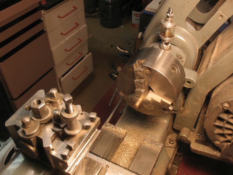
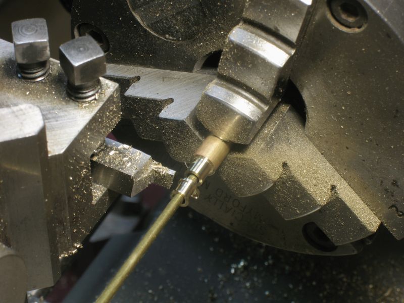
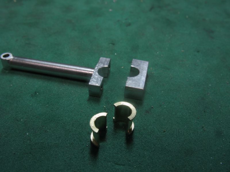
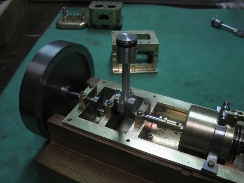
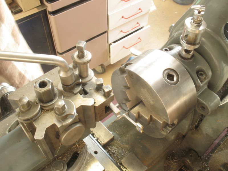
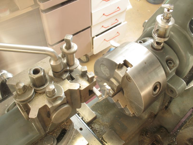
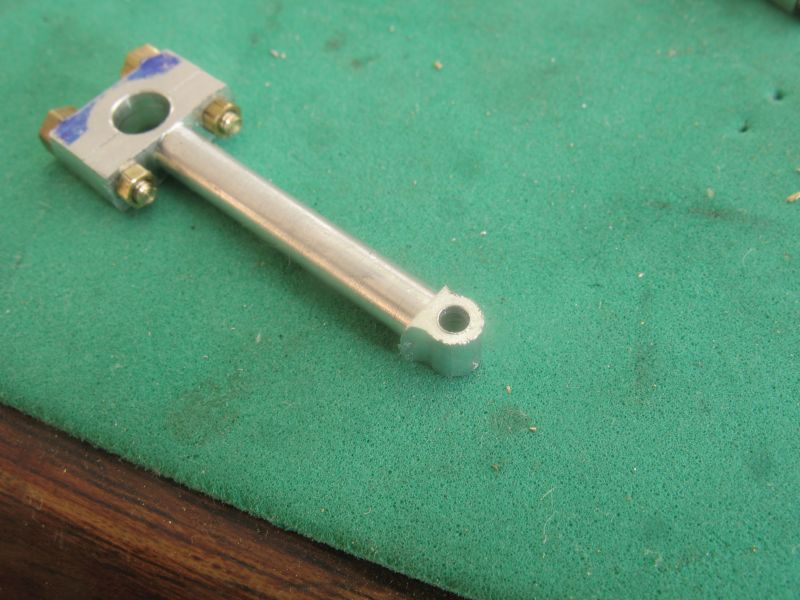
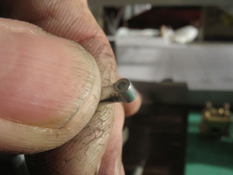
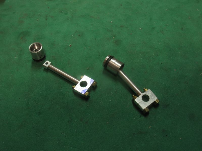
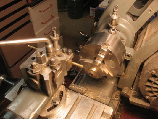
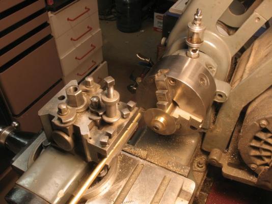
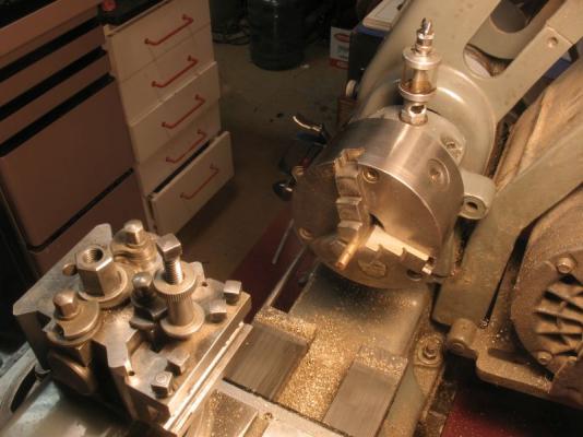
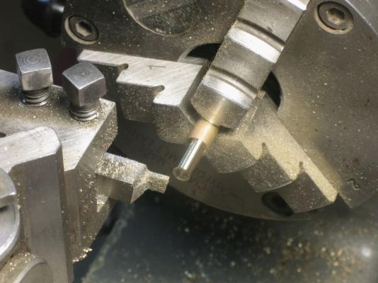
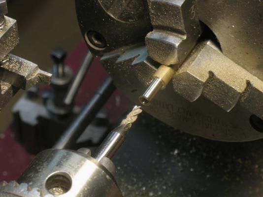
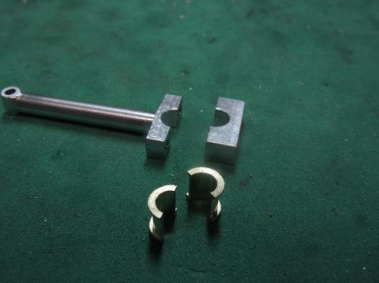
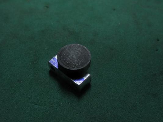
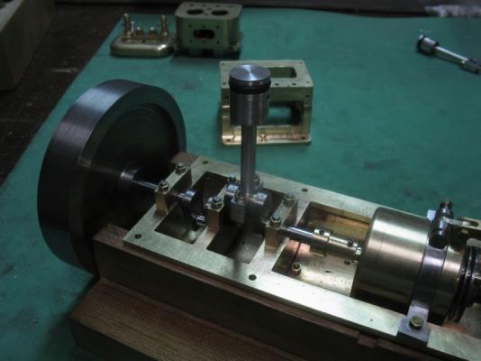
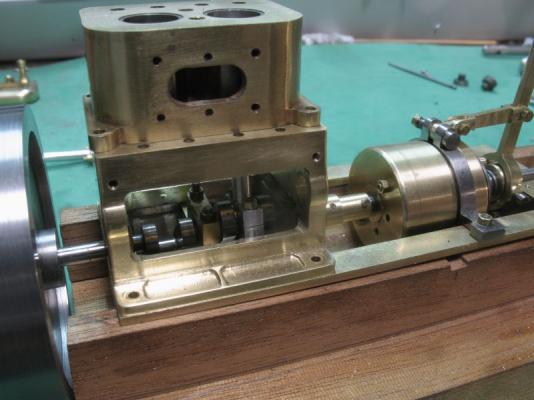
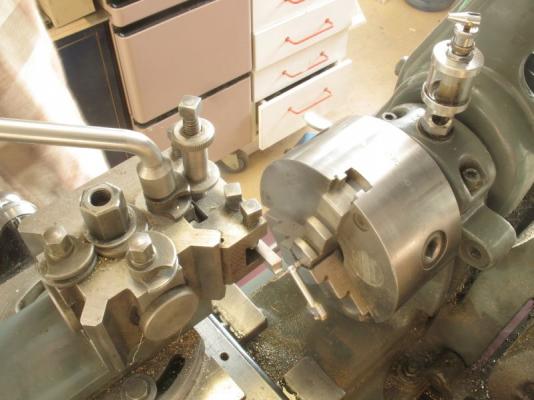
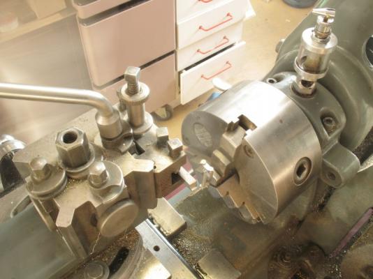
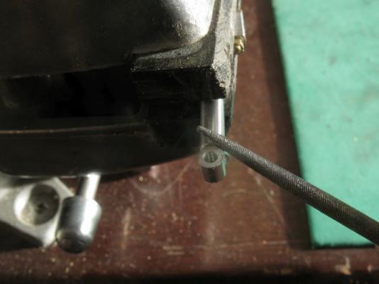
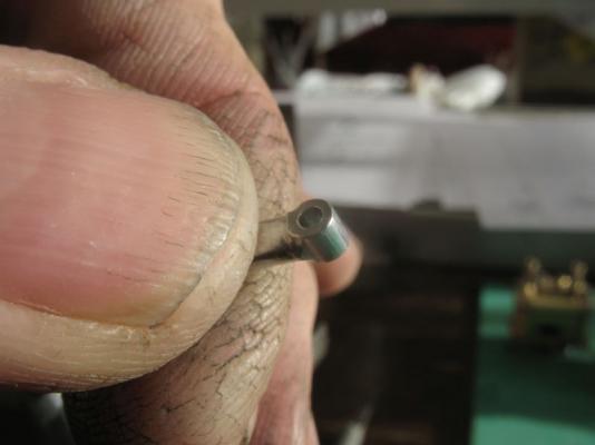
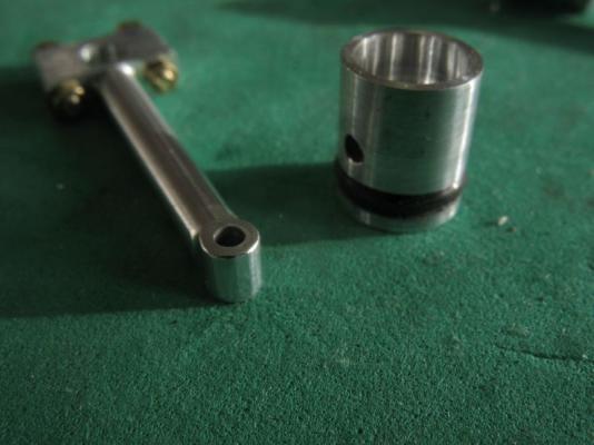
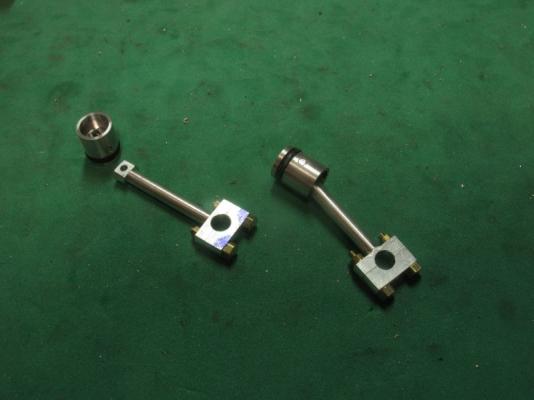
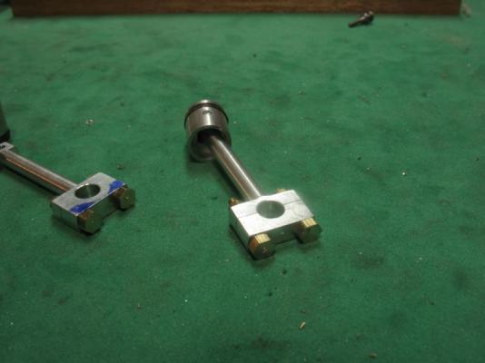
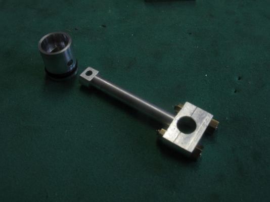
Nigel thanks for your kind comments I am happy that you are enjoying the journey. Druxey, thanks. Mark, in a word Yes. I'm pleased you have found some of these processes useful. Steve and Mark, that make at least three of us Thanks for all the likes Pressing on with the con rods today the first task was to split and solder the brass for the big end bushing, I decided to make these individually so that I could check that it was going to work. slitting the rod soldered ready for machining turning down to the flange diameter The final bore was done with a 1/8th end mill after first using a centre drill then a 3/64th drill. Turning the central part was very tedious with very light cuts and double checking the diameter after each pass of the tool.The bush was then parted off. Tthe bore is .125" and the body diameter is .156" so the thickness of the bearing wall is only .0155" and that made me very cautious. I used a soldering iron and a pair of tweezers inside the bore to unsolder the bushing, it popped apart very cleanly. I turned and hardened a new button for the bottom of the big end of the con rod. when everything was cleaned up the moment of truth,...... it fit Yea...a little stiff but not much Then I wanted to check the height inside the cylinder and was very pleased with the outcome, I did notice that I plopped the top part of the crankcase on backwards after uploading the photographs... excitement I guess. Now I have to repeat the process all over again tomorrow and I also have to relieve the bottoms of the cylinder liners to clear the con rods. I had drawn this in the details but have not done it yet, once that is done tomorrow the the piston with be able to move up and down in a complete cycle Michael

-
Beautiful workmanship on the mast tops and rigging Doris, The last close up of the top and rigging demonstrate clearly your great skill. Your photographs are also always clear and well composed. Happy New Year to you and your family. Michael
- 883 replies
-
- 2
-
-
- royal caroline
- ship of the line
- (and 1 more)
-
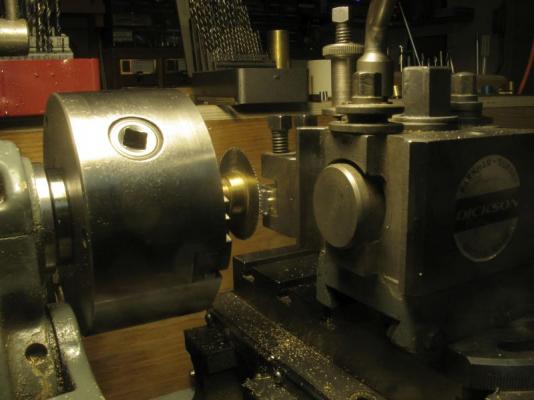
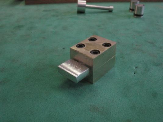
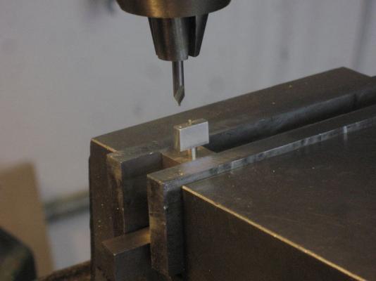
This was the sequence for the top end shaping. the first shots showing the rotational shaping in the lathe using the chuck as a vice while moving the cutter back and forth. Next using a rat tail file to finish off the shape after filing but before final clean up. ready to assemble Michael

-
Druxey thanks I did search in a couple of my dictionaries and the two word seem to come closest with the definition of a small key or small wrench for tuning stringed instruments as in the harp or piano by turning the pins to which the strings are fastened. The definition of wrist pin is a pin joining the end of a connecting rod to a piston Cheers Michael
-
Fantastic work as always Ed I am enjoying your build immensely. i am glad that you made the decision to prepare a book about it. A happy and prosperous new year to you and your family. Michael
- 3,618 replies
-
- 1
-
-
- young america
- clipper
- (and 1 more)
-
Row, I am curious about the holes, again use a pecking process to drill the hole very small cuts and continually pull the bit out all the way to clear. John thanks, and again for all the likes Michael
-
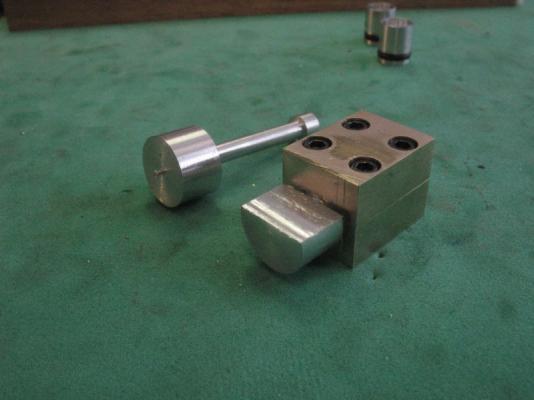
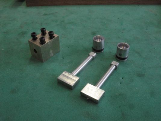
I finished prepping the other rod this evening Also forgot to post the pic of how the big end was split. I used the slitting saw in the lathe. I also turned up a pin out of steel to slip the wrist pin hole onto so that i could use the lathe as a shaper. I used a round nosed tool bit sideways and moved the carriage back and forth as the top end was rotated incrementally by hand to shape the top round. The first one is fixed to the piston I forgot to take pics of the shaping I will set that up for the second one tomorrow. Michael
-
Carl and Bob, thanks, Sometimes it seems that the jigs and fixtures take longer to do than the parts themselves. Michael
-
Nice, Ill be following along too Bob Was that because they were lost for words? I couldn't resist.
-
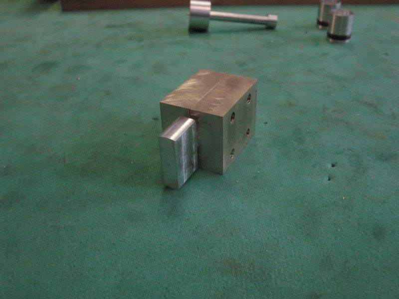
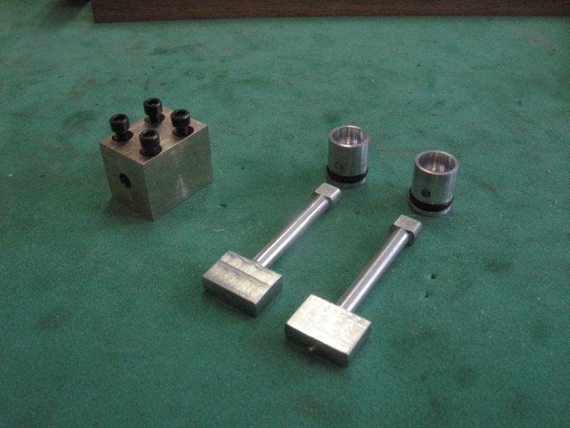
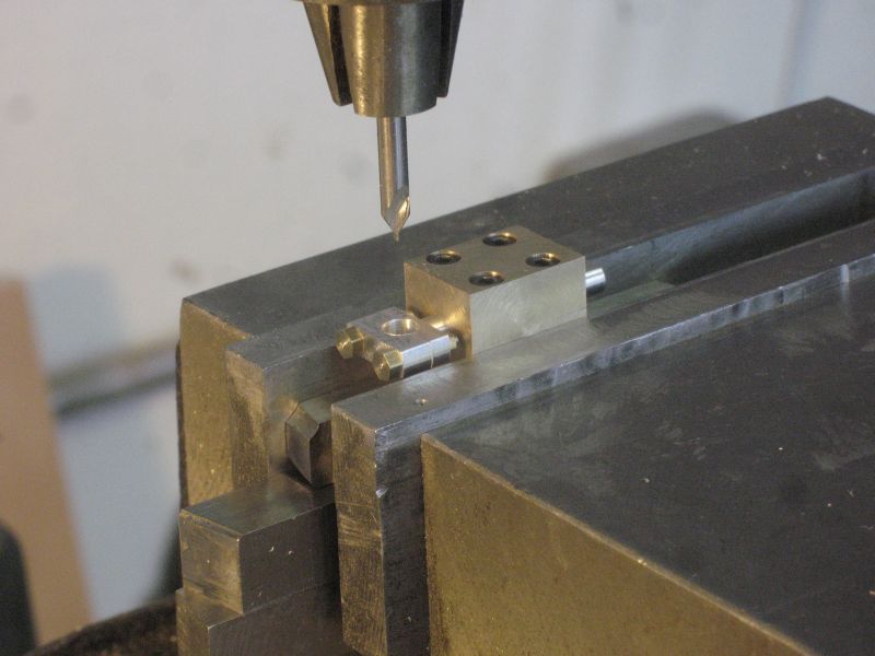
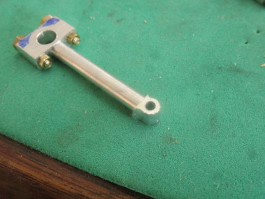
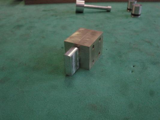
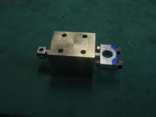
Thank you all for you kind comments regarding the notes on the way I go about drilling holes. and thanks for all the folk who liked it. Pressing on with the con-rods the first order of business was to make a brass split holder for some of the following operations this was made from 2 pieces of 1/4 x 3/4 inch bar stock before I drilled and reamed the 1/8th hole through the joint I added two small slivers of .0015 shim stock to spread the bars so that when the con rod which is 1/8th is placed between them the allen head cap screws will have that .0015 missing so that the bars squeeze the shaft of the con rod holding it firmly. The first three picture show the stage 2 of shaping the rods the round ends have now been reduced to the correct width. The next operation was to drill the holes for the split big end these are clearance for 0x80 bolts After the holes were drilled the assembly was taken back to the lathe for the slitting saw to cut the big end into the two parts. they are temporarily held together for drilling out to .156" for the bushing. here they have been drilled and the hole for the wrist pin followed by indexing 1.004" (I'm not sure how it got to be 1.004" I'm just following the drawings) The area marked in blue is to remind me that I will need to shape the keeper later and remove that areas marked with some files using a hard button to ensure that the curvature is maintained. I also need to turn up some steel bolts for the big end, and make the split bush, I will do this by soft soldering a couple of bars together then turn the bushing in the lathe then unsolder them ready to fit the rods. removed from the jig so that I can get the second one to the same stage. I'm tired time for a nap. Michael

-
she is coming together nicely Denis, Masking tape my man, use masking tape to lay it out. and start with slightly smaller ones than your final. Michael
- 956 replies
-
- 4
-
-
- andrea gail
- trawler
- (and 1 more)
-
Congratulations Jan the ships look beautiful crisp and clean work. I am looking forward to your new build. Michael
-
Good to see some more work coming from your boatyard Pete. I love the shot of the keel on the drawing which was obviously done pre computers, complete with the table of offsets. Michael
- 112 replies
-
- 1
-
-
- buzzards bay
- herreshoff
- (and 1 more)
-
Nice to see the planking take shape Mark using the different woods for the colour contrasts is a great way to go. Michael
-
Thanks Nils and Row for your kind remarks, and to all who added likes. Mark these are the drill bits I have purchased they are good quality general purpose from Acklands Granger The 1/8th shank bits came as a box of mixed sizes, I got them from Lee Valley and that they got them from Drill bit city but I am only guessing on that one My centre drills are like this one ,in these sizes 0, 1, 2, 3. Mostly I sharpen my drill bits as they get dull. the ones I use the most are # 50-59 #'s 20, 43, 33, 36, 12, 8, 11, 29, 25, and most of the fractional from 1/16 to 1/2 in the 1/64th inch increments I have a few metric drills specific to metric taps. The smaller bits I sharpen with a small slip-stone holding both the drill and slip-stone in my hands for the bigger ones I use the big diamond wheel that I got from an optician as a discard when they purchased new equipment. With the bits that I use a lot for brass and plex I use the slip-stone to put a flat on the cutting edge so that it does not grab but scrapes Michael
-
Miniture machine screw sizes
michael mott replied to grsjax's topic in Metal Work, Soldering and Metal Fittings
Pat Thank you that is beautiful, I will check out the link. Michael -
Very nice drawings Mark. Watching that slow motion of the inside of the side of the test panel of the ships side, it is a wonder that anyone would venture below decks during a sea battle. what a dangerous place to be. michael
-
My you work fast all that stuff happened as i was composing my last few words. Michael
- 956 replies
-
- 1
-
-
- andrea gail
- trawler
- (and 1 more)
-
Hmm kindling in zip lock bags.... not a bad idea. It is amazing what one can do with a few scraps of wood isn't it I like the last barrel press, I guess they were a weighty band. Michael
- 956 replies
-
- 2
-
-
- andrea gail
- trawler
- (and 1 more)
-
Jud this is what surprised me the most as well, I am following the same practice as many of the model engines that have been built by the model engine builders and the most important thing is to make sure that the cylinder liner is well polished when using the O rings which is opposite to using cast iron rings. There are a number of tutorials for making cast iron rings down to 3/8th diameter but it takes a bit of practice and some really good cast iron bar stock to be able to make them successfully. JKLee and Omega Yes it is a different area of modelwork but basically one only needs to focus on the task at hand and break it down into incremental chunks small chunks I admit. The way I see it is that each time we change materials or scales we encounter new challenges and have to consider using different tools for some tasks. Remco the short answer is no, that said I think that the basic issue with drilling small holes is one of sequences. 1) When drilling into wood with very small drills 1/32 and down to the small #'s 60-80 the wood is not a consistent homogenous material, it is organic and full of subtly different hardness's and textures and this is I believe the main reason for breaking the bits when using a drill press or milling machine, the other issue is the speed of rotation of the bit, the smaller the bit the higher the speed the machine needs to run, this is counter intuitive to the way we use them by hand in pin vices which is technically a snails pace by comparison. I think the difference is that when using a hand held pin vise we use much less pressure and can "feel" the drill cutting, remember our fingertips are one of the most sensitive parts of our bodies with the possibly the most nerve endings. 2) When drilling metal the key is to ensure that the start is exactly centered, and I mean exactly, this can only be accomplished by using a centre drill to spot the centre first my centre drill for the small drills cost me $27 for a tiny 1/8 shank centre drill this means the for every hole I have to do a number of things first decide on where the hole is going to be, this entails laying out the position on the material and fixing the material solidly to the drill press or mill, I tend to use the numbers and not a centre punched divot, by that I mean indexing from two or more sides depending on the shape, the centre drill takes the place of the punched divot. 3) The way I index is to use an edge finder or centre finder to set the datum on at least two edges then I can simply set the dials on the table to 0 and them index them to the two coordinates x and y that is the centre of the hole, I do this regardless of the size of the piece I am drilling, it is a habit. The quill of the mill also has a dial so that I can set the tip of the drill to 0 at the surface that way I know how deep my hole will be if I am not going all the way through. if I am going all the way through I sometime use some wast material as a support so that the drill does not catch and snag on exit one of the biggest causes of broken drills in the smaller sizes, the other is the drill bending because the start was off centre from the centre axis of the rotation of the drill as it gets deeper the bending forces increase often snapping the drill. 4) The next important thing regarding wood or metal is ensuring that the drill flutes do not get clogged with the material what you are removing out of the hole, it has to go somewhere so raising the drill out of the hole frequently allows it to escape (this is usually centrifugal force that throws it off the drill) sometime the material is "gummy" some brass and some aluminum can be this way and so a lubricant (Varsol or Paraffin works well) is needed to keep the bit slippery, a cutting oil for steel. Obviously one doesn't need the lubricant on wood but it can clog the bit even more quickly than metal, so small "pecks" (frequent raising of the drill to clear the wood off the drill) a small fine stiff brush can be very helpful to clear this debris out of the flutes. The last thing to remember is the depth to diameter ration of the hole deep holes are more difficult to drill for all the above reasons Finally use the best quality drills you can afford and I always use a centre drill to spot the hole, this means that if I am drilling a number of holes I can drill all the centre spots first (following all the numbers on the index map drawing) then go back and follow all the numbers again with the drill this is the fastest way when I an drilling multiple holes to the same depth. Or I can change the drill from the centre drill to the hole size drill with each cut, it depends on what I am drilling and for what purpose I choose which way to go. I hope this answers your question. All of what I just said applies to using a drill press mainly, and also ensuring that the work is rigid (clamped in some way is also very important) when working freehand or using a hand held drilling devise drill or Dremel type tool similar conditions apply but they are not quite the same, and I take my hat off to all the steady hands out there, drilling treenail holes. I cringe when I read of using a # 70+ drill bit by hand. Omega actually this really applies to your Ingomar yacht model Michael