tkay11
-
Posts
1,802 -
Joined
-
Last visited
Content Type
Profiles
Forums
Gallery
Events
Everything posted by tkay11
-
 You might also get some ideas from the Dutch herring boats of the period. I think I read somewhere that they were very similar to the fifies (perhaps in the book 'Inshore Craft: Traditional Working Vessels of the British Isles' by Basil Greenhill, but I may be mistaken. They operated in the same area of the North Sea. Ab Hoving is an expert on Dutch vessels so you might pm him, and Kees de Mol has a nice model of a Dutch Herring Lugger which shows a wheel positioned similarly to that on the Lady Eleanor. Model Shipwright no 118 had a modeller's draught and plans of the Reaper . However, I don't think you'll find details of the steering mechanism there. Tony
- 195 replies
-
- 1
-

-
- lady eleanor
- vanguard models
- (and 1 more)
-
Great to see you're into the mods, B.E. I was interested in your comments about the look of the deck, so I had a look in Edgar March's book on sailing trawlers but there's not much there on decking. I know the fifie was a drifter rather than a trawler, but if you don't have the book and if it helps, the following is what is said about smack design: "The covering board of 12 by 2½ in. oak was laid over the heads of the frames, stanchions fitted through the mortices and bolted to shelf or frames, the deck planks were pitch pine, 5 by 2½ in, with a margin plank varying in width according to the beam of the hull. Planks had to be joggled into the covering board when the "snape" or diagonal cut across the width left a nib-end less than 2in wide, a sliver edge being impossible to caulk." Also in case you've not already seen it, there's the website on the restoration of the Swan which shows pictures of the deck, but that is in its modern re-incarnation so probably is of no use to you. The one picture of it in its original state doesn't seem sharp enough to see the deck planking details. The book on the Swan may give you more if you need it. Tony
- 195 replies
-
- 1
-
-
- lady eleanor
- vanguard models
- (and 1 more)
-
Don't forget the Taig/Peatol lathes. They're excellent for model makers, cheaper than the Sherline, have a huge range of accessories, lots of instructional videos on the web, and a very nice idea for a tailstock. They are also available quite often on eBay. I bought mine in the UK with a huge range of accessories some years ago for £400 which at the time would have been a little over US$550. I have the tool rest for wood turning, so although I have the perfectly good Proxxon wood lathe, I now only use that for the longer pieces such as masts. Tony
-
Phosphoric acid or rust conversion gels are said to blacken steel. I've never tried it myself, though. Tony
- 435 replies
-
- 2
-
-
- vanguard models
- alert
- (and 1 more)
-
It sounds simpler than building up the gunports again. Unless, of course, you have a mind to practicing skills. Tony
- 435 replies
-
- 3
-
-
- vanguard models
- alert
- (and 1 more)
-
Wonderful! A real treat to have followed and learned from! Thanks! Tony
-
What a nice imaginative idea! I'll enjoy this. Tony
-
It's a lovely model you've been building, and the Caldercraft models are generally amongst the top brand of kit makers. To answer your question about the rigging, I can suggest three lines of thought. The first is to get Petersson's book "Rigging Period Ship Models". Among the rigging experts there is a lot of banter about inaccuracies, but it does give a very good simplified introduction to rigging square rig ships. It has beautiful diagrams that break down each part of the rigging separately so that you can step back from the overpowering complexity of a rigging diagram. There is also Mondfeld's excellent book on Historic Ship Models. You can find both books used, at reasonable cost, on eBay, Amazon, Alibris or AbeBooks. There's even a Kindle edition of the Petersson book. The second line of thought is to go to the National Maritime Museum's website and research your ship. The may well have plans available. Finally, you can search for other builds of Mars on the web, which may give some help. Tony
-
Great idea! I wish I'd had the thought of using spacers before. Thanks very much, I'll definitely do that in future. Tony
-
Very interesting, because I've ordered a card kit (Allège d'Arles) and I was thinking of using plywood instead of the card for the internal frame. Tony
- 179 replies
-
- 3
-
-
- shipyard
- wütender hund
- (and 1 more)
-
Really nice and impressive work! Were the gunports so rounded? Tony
-
He's a very well-known authority of merchant sailing ships. You can visit the David MacGregor Library at the Brunel Institute in Bristol. They have a collection of his plans which you can purchase. It's at https://www.ssgreatbritain.org/brunel-institute/library. I haven't read any of his books, though, but they are well-reviewed. Now you've brought up the topic, I'll get the first in the series. Thanks for doing so! Tony
-
Moxis, that's an excellent piece of work, and a great idea. Thanks! Tony
-
This question has been asked so many times that it may be better for you to have a look on the various replies on this site. The answer is problematic because it all depends on the type of kit you want, the level of detail, the cost, the scale, the material it is made from, the level of instruction, the materials in the kit, your expectations, your level of skill, your previous experience etc. So different people will provide different opinions. I suggest you look at the large variety of Victory build logs to make up your own mind. Tony
-
First thing: take a deep breath, think about it, and don’t give up just yet. What is it that you are finding difficult, precisely? If you can narrow it down, just ask a question. This is why it would help to start a build log, as it shows the step at which you find difficulty and people will come to your help. Every modeller started somewhere, will have made mistakes and learned from them. I would bet that your particular problem has been encountered by many here. of course, as I suggested, you may not like the hobby or overcoming the problems, but I’d suggest at least giving it a go. Tony
-
Sound advice, wefalck. Thanks! Tony
-
If you use PVA for sealing knots, it's the white version you want, rather than the yellow versions. Tony
- 11 replies
-
- 1
-
-
- lady nelson
- amati
- (and 1 more)
-
Thanks again, wefalck, for the time and experience you put into providing answers! I'd thought about brass paint but was worried about the appearance being of paint rather than brass or copper. Tony
-
ancre La Jacinthe 1823 by guraus - Scale 1:48
tkay11 replied to guraus's topic in - Build logs for subjects built 1801 - 1850
Thanks very much for the information. It’s beautiful wood. Nice idea to use flooring! Tony -
Some great ideas, wefalck! I’d thought of a 6mm plastic test tube which I could cut a section out of and hen cover with copper leaf. But I like the idea of trying to shape the brass rod. I also thought that the box type of portable binnacle might be more likely. As to the plexiglass I wasn’t clear that this type of binnacle had a glass cover, assuming the compass had one. I have already found a good compass drawing to fit inside. Thanks a lot for your very good advice! Tony
-
Your difficulties and questions show the value of studying other logs. CA glue overflow is extremely difficult to get rid of. It stains the wood. I can only think of soaking in acetone which may necessitate removing the part. It’s worth avoiding by using extremely sparingly, applied with a pointed stick or the filed off end of a sewing needle. For sealing knots nail varnish or similar is often recommended. Some use dilute woodworker’s PVA. PVA can also be used diluted to stiffen fabric. Tony
-
ancre La Jacinthe 1823 by guraus - Scale 1:48
tkay11 replied to guraus's topic in - Build logs for subjects built 1801 - 1850
I am thinking of making this my next build and was reviewing yours. Could you let me know the wood you used for the masts? Tony -
The other cutter that is very similar to the Lady Nelson is the Sherbourne. There are some worthwhile build logs you could look at, especially those by Sherbourne Tar, Gregor and dubz that go into a lot of the historical detail, the different ways or rigging and belaying, and modifications from the kit parts you may want to consider. Tony
- 11 replies
-
- 1
-
-
- lady nelson
- amati
- (and 1 more)
-
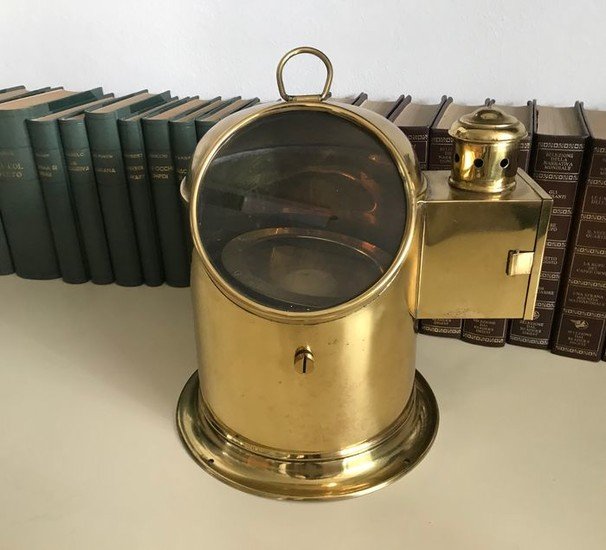
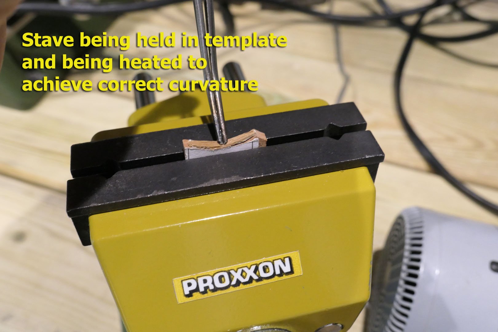
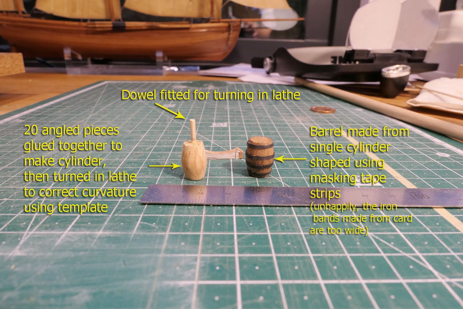
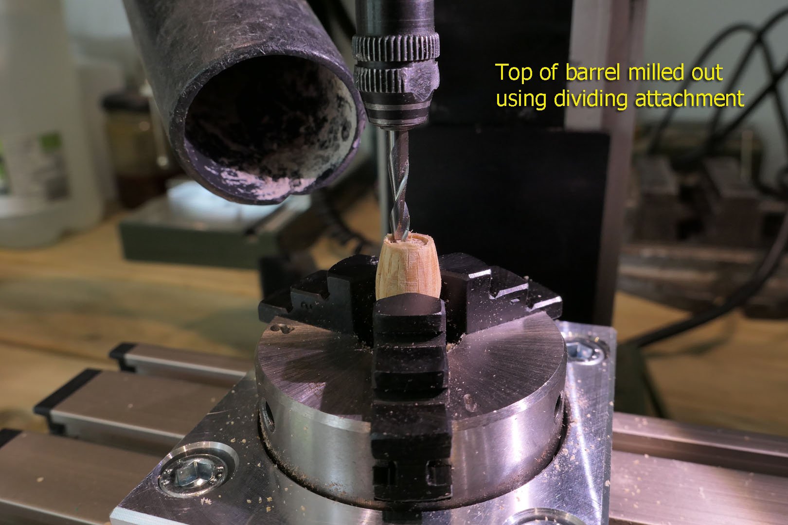
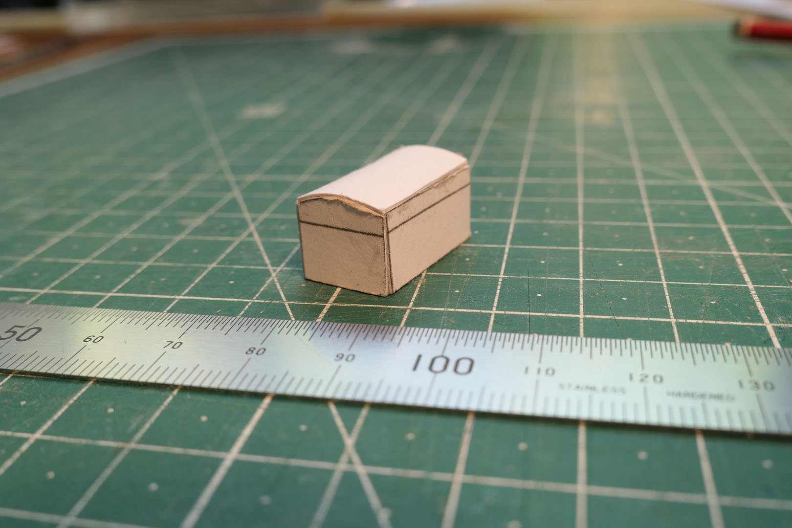
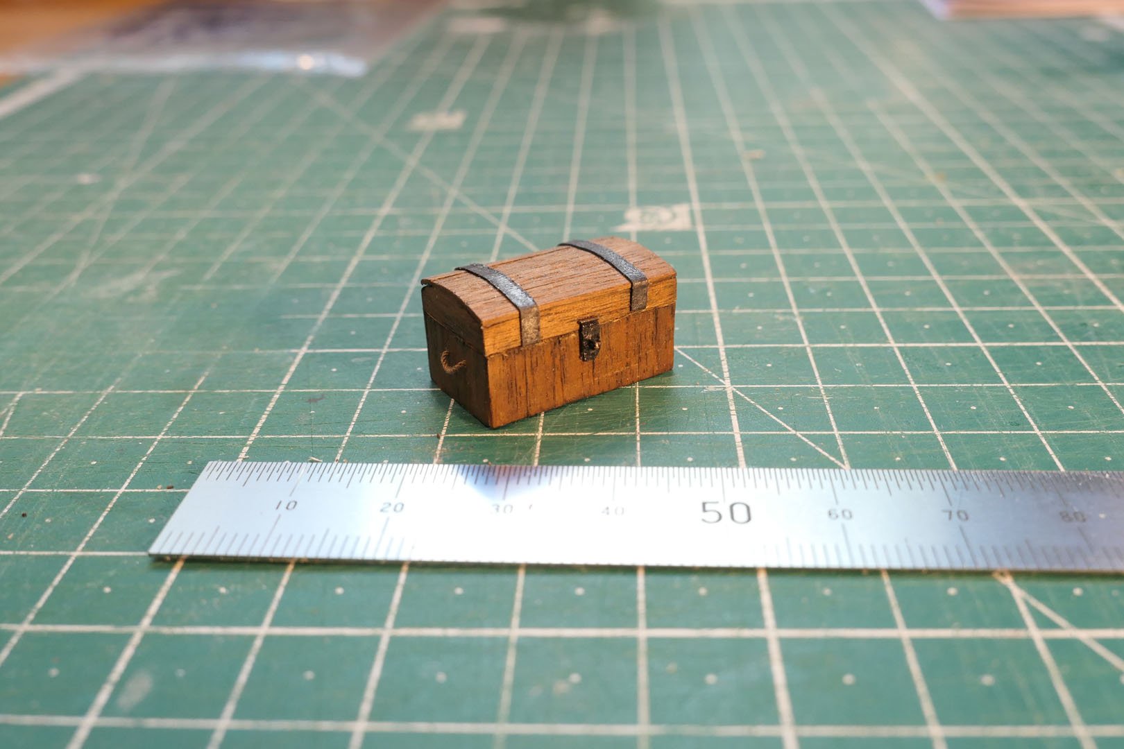
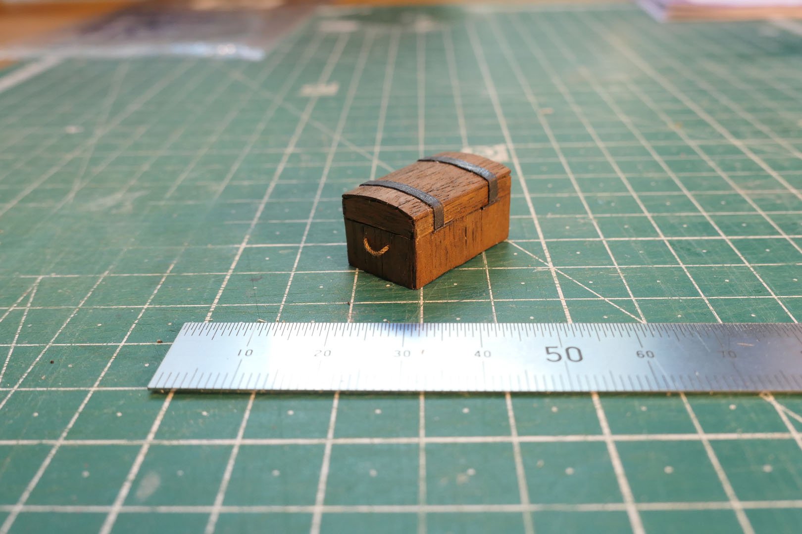
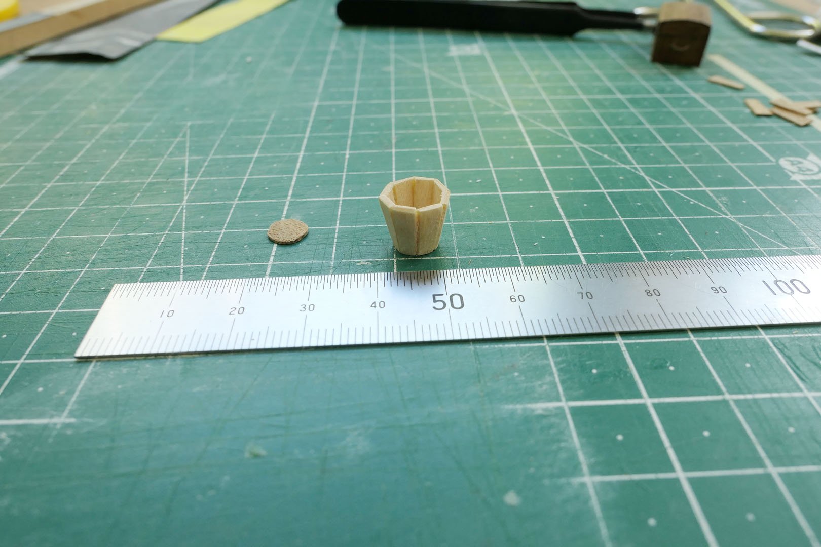
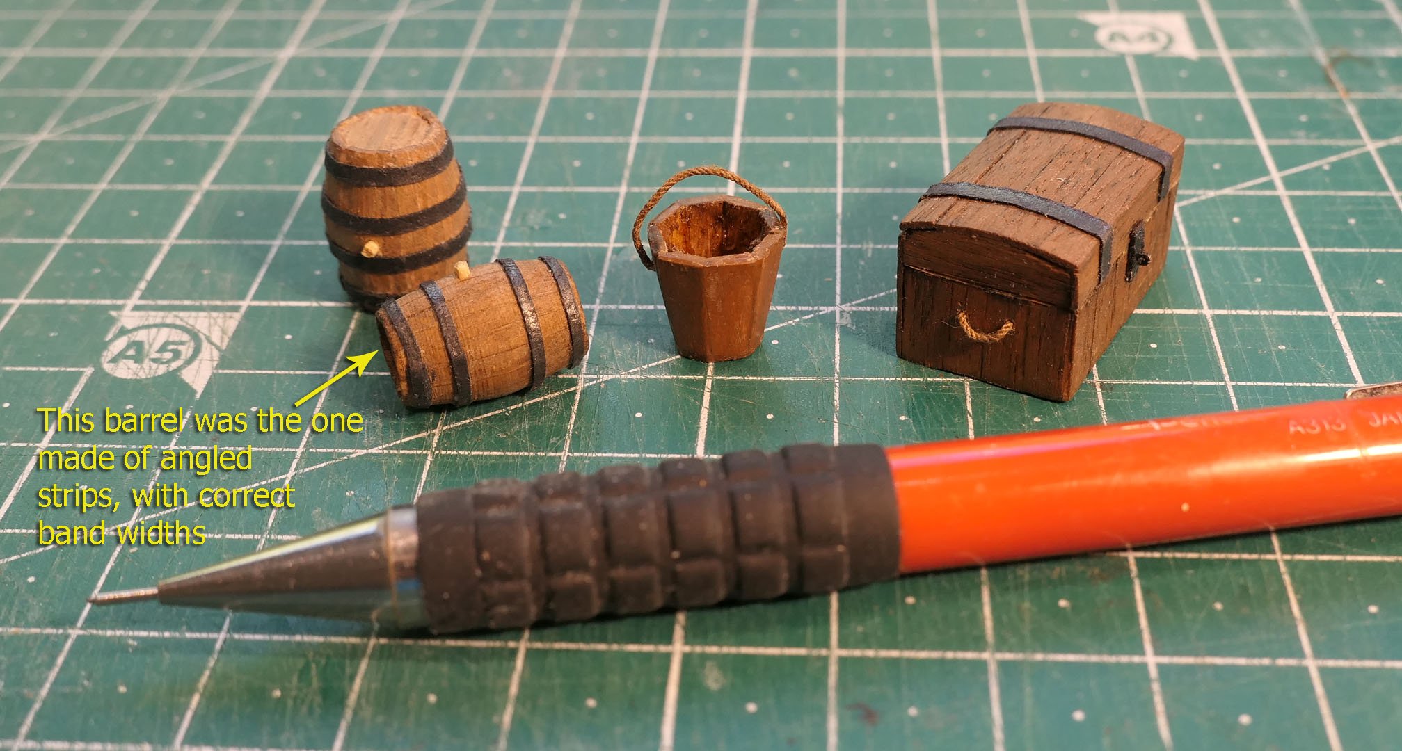
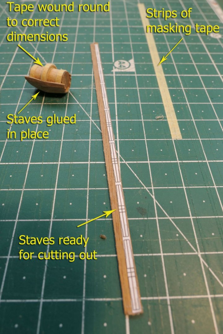
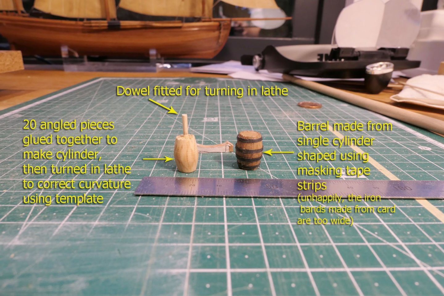
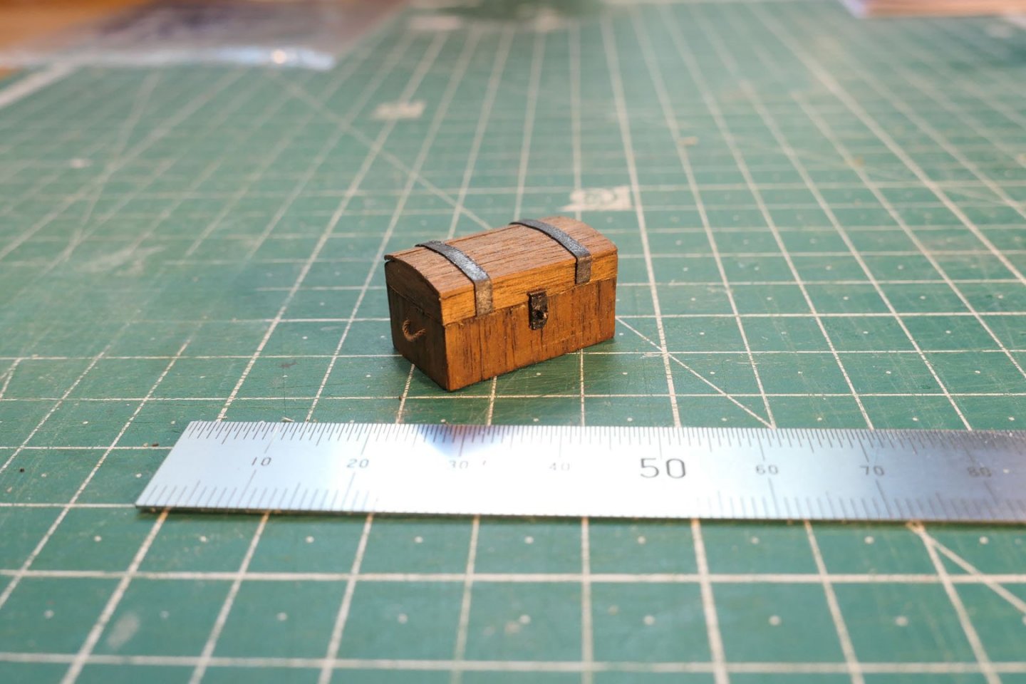
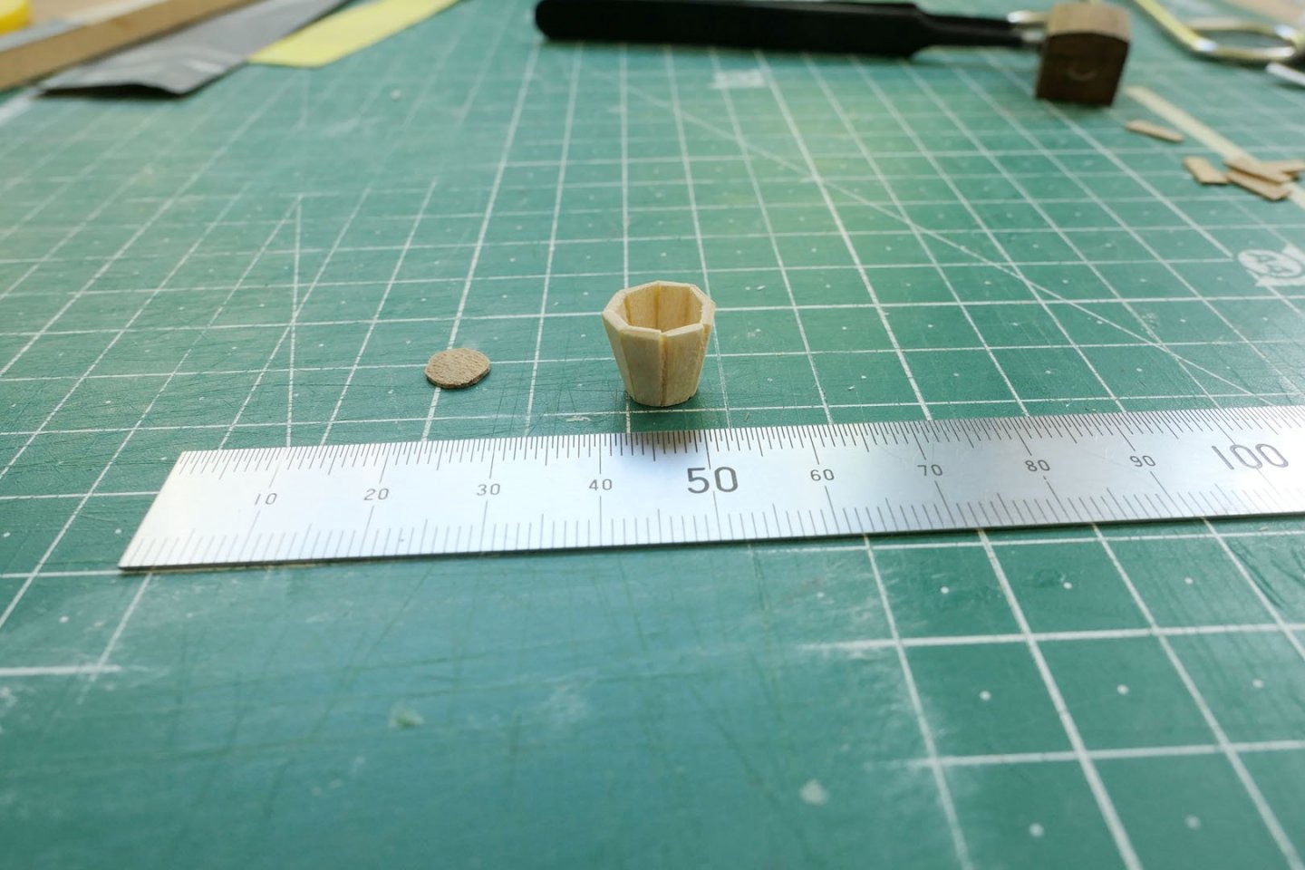
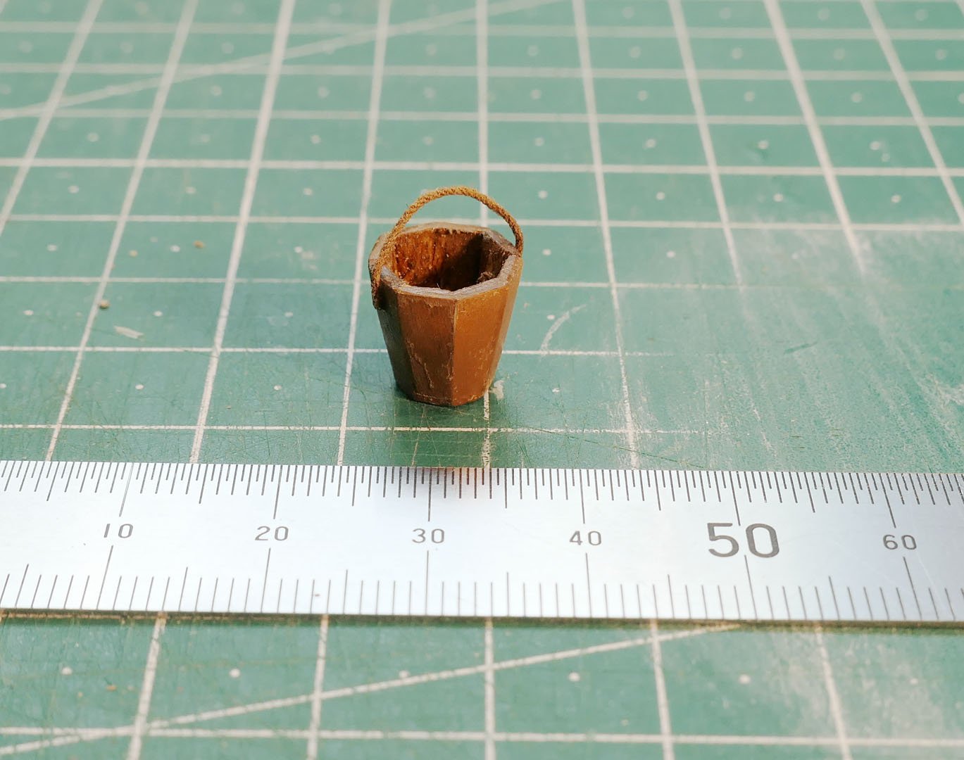
Barrels, Sea chest, Bucket In providing equipment I decided at least on the barrels, sea chest and bucket in addition to the oars. I’m still debating whether to try to make a portable binnacle, but reckon this boat would not have been used for any journeys requiring its use – so may decide to leave it out. Barrels As I had not made barrels before, I looked into the different ways of making them, and decided to try two of them. The first method was using a solid core of a wood dowel to which is added the width at the middle by ringing it with wood strip or, as I did, a strip of masking tape. There were a number of problems with this method. The first was that no glue I used would stick satisfactorily to the masking tape. That is why it would have been preferable to use paper strips or else strips made of very thin wood shavings. I ended up using excessive quantities of PVA. The second problem was that given the compressibility of the tape, it was difficult to keep to the width of the staves so that all would have the recommended 4” width (at scale). As a result there was a lot of variation in the width – which was to some extent compensated by sanding. The big advantage of this method is that the staves overlap the ends of the barrel, so requiring no further drilling out to leave an overlap. The planking on the ends of the barrel is of course placed first, before placing the staves. I found it was useful to soak the staves first and curve them in a template jig using a hair dryer for rapid shaping. The second method involves cutting long angled strips of wood and gluing them together to form a cylinder. I chose to have 20 staves cut to an 180 angle (20 x 18 = 360). This was because the stave width at the circumference of a 10mm diameter cylinder would then be equivalent to 4” at full size. I found this part to be very simple to do using the Proxxon FET bench saw angle function which has a nice accurate guide to the degree of rotation. The barrel was then fixed on to a dowel which could be held in the lathe, and it was shaped to the correct curvature using a template. The barrel was then stained using walnut crystals, and bands placed with strips of black card. You’ll see the photos later in this post. Sea chest I made the chest using a card base on to which wooden planks were glued. A locking plate (made of card) and stanchion (0.4mm copper wire) were added, along with rope handles, two 0.5mm brass rod hinges and two supporting bands of black card over the curved top. Bucket Making the bucket was initially very puzzling to me. I could see others have made the bucket using the same method as for the barrels – namely the making of angled strips bundled together to form a cylinder, shaped and then hollowed out. I just could not see a simple way of hollowing it out while keeping the angle of the staves. In the end all I did was make the staves individually using as a guide the end dimensions of 10mm tall with a 7mm base. In order to keep it simple I restricted myself to 8 staves for which I made a pattern, glued to a strip of wood, then cut and angled the edges with a razor. I then took the gamble of just gluing the edges to each other, one stave at a time, in the knowledge that the grip of PVA would be sufficient to keep the parts together while adding them to one another and then curving into a cylinder. I left the cylinder to dry overnight, then glued the base on. As I had used white maple, I tried staining with my walnut crystal stain, but it didn’t alter the colour very well, so I had to paint with brown acrylic and finish off with a home-made shellac varnish. I added a rope as a handle. This now leaves me with the choice of whether to go with a binnacle and a boat hook. I can’t see my way to the method of making either one, but I’ve asked a question on the forum about the binnacle and I’ll see what answers I get. Otherwise I’ll be labelling this build as complete. Tony


- 124 replies
-
- 17
-
-
- longboat
- Chaloupe Armee En Guerre
- (and 1 more)
-
I am trying to finalise the equipment for my build of M. Delacroix's Chaloupe Armée. One of the possibilities is to include a portable binnacle of the type shown below: At least this is the design in Dane's card model of a French 18th Century Longboat. I have no idea as to whether a binnacle would have been carried in an armed longboat, or whether this is even the type. However, I would be very grateful for opinions: 1. On whether one like that in the photo would have been carried, or whether another type would have been carried. 2. How I might approach making a round-topped cylinder (probably in brass) that could be cut away to reveal the compass. Dane's card model suggests making the dome from a series of triangles around the perimeter that would then be bent inwards to meet at the top as shown below: I thought of approaching this by cutting it out of 0.04mm brass shim, but that would leave the problem of bringing the triangular parts together in a seamless way that would also look good. The dimensions would be something like 6mm diameter and 10mm high. So all suggestions as to how to proceed are welcome. I don't mind if the suggestions including leaving this out altogether! With best wishes to all those in lockdown, Tony