


gjdale
-
Posts
4,894 -
Joined
-
Last visited
Content Type
Profiles
Forums
Gallery
Events
Everything posted by gjdale
-
 Thanks Craig and welcome aboard. Progress is being held up at the moment waiting on delivery of more paints for testing. The COVID lockdowns give us more time for hobbies, but at the same time they slow down the mail system considerably (mainly due to overload from all the people with more time on their hands - sort of a Catch 22 situation really!).
 -
Welcome aboard Gary. The paint trials continue. I’m still waiting on another delivery this week. Hope to have the paints sorted out by this weekend.
-
Wow! You had me holding my breath for a while there Glen. Glad you were able to recover the situation. Hope it all goes well with the next attempt.
-
Nicely done Andrew. I’ll bet there were some nervous moments in that little job!
-
A lucky escape Ryland! Glad to hear no significant damage was done.
- 263 replies
-
- 1
-

-
- Medway Longboat
- Syren Ship Model Company
- (and 1 more)
-
Congratulations Alan! Very glad to see that your perseverance has paid off so well.
- 460 replies
-
- 4
-

-
- Finished
- Flower-class
- (and 1 more)
-
Glad to be able to help Glen. The finished ship is looking good. Can’t wait to see her go into the bottle.
-
NRG VIRTUAL WORKSHOP - AUGUST 21
gjdale replied to kurtvd19's topic in NAUTICAL RESEARCH GUILD - News & Information
Thanks Kurt - just registered. 😊 -
NRG VIRTUAL WORKSHOP - AUGUST 21
gjdale replied to kurtvd19's topic in NAUTICAL RESEARCH GUILD - News & Information
Thanks for confirming the recording Kurt. If space is limited for the live event, won’t registering take up some of those spaces unnecessarily if we only plan to view the recording? An announcement here when the recording is available to members would surely suffice? Sorry to be a PITA - just looking for the best outcome for all. -
Glen, You might try dabbing some thin CA directly to the end of the thread and carefully rubbing it in. This will give the thread end a solid “needle” like form that may help with threading it through those tiny holes. Once threaded, you can snip off the hardened end.
-
NRG VIRTUAL WORKSHOP - AUGUST 21
gjdale replied to kurtvd19's topic in NAUTICAL RESEARCH GUILD - News & Information
Kurt, Not sure what you mean when you say "can typically view...." Will this workshop be recorded? If so, do we need to register first in order to be able to view the recording? And will you post info on how to access the recording after the event? Those of us challenged by substantially different time zones would appreciate the opportunity to see the workshop without having to be up in the middle of the night..... Don't mean to sound narky, but the info provided above is a little vague. -
Thanks Popeye - I do believe I already have some of the cement/glue. 😊
-
Looking good Glen. Your log prompted me to drop a heavy hint to my wife as I have a birthday coming up in a few months time….😁
-
Looking god Bill. For boat name graphics, have a look at Callie Graphics (https://callie-graphics.com). I used hers for my Dumas build. She is great to deal with, will design to your specs, send you proofs to approve prior to production, and her service is second to none.
-
Thanks Popeye. Yes, I’m fast becoming a fan of lacquer paints, and Alclad in particular. I’m also experimenting with Stynylrez primers. Although they are not a lacquer, they seem to work well with everything. Unfortunately, every time I decide to try something else, I have to wait for the postal system to catch up ‘cause virtually none of it is available locally these days.
-
Can’t wait to see your interpretation of Chris’s design B.E. I’m sure it will be something special, so I’ve pulled up a front row seat to follow along.
- 857 replies
-
- 4
-
-
- Sphinx
- Vanguard Models
- (and 1 more)
-
Thanks Nick. Paul is another of the YouTubers I quite like and that is quite a good demo he does in that link. He also mentioned Yellow as a primer under Red, which is going to be my next test as I’d read somewhere, sometime that this was a good combo. Waiting on the next paint delivery now……
-
Glad to see you back at it Bob. I look forward to the next update.
-
Thanks Ken. And thanks Ron - that’s one of the guys I’ve been watching. I think he’s pretty good.
-
Thanks Wefalck for that info. I hadn’t considered not using primer on the metal parts - painting is certainly not my forte! I think I’m going to stick with the primer though. Egilman - thanks for the Desert Cart link but at $91 a can, I think I’ll pass. That is the first time I’ve seen it offered for shipping to Australia though - I wonder if it would actually let me order it if I went through with it…..I’ve seen similar adds like that and when you go to checkout, suddenly it doesn’t ship to your location. The second link is not for the Foil paint - that’s the Premium paint that I already tried and didn’t like. I’m pretty happy with the Alclad colours so far. They are reasonably obtainable, a fair price and have had some very good reviews. Thanks everyone for the input - much appreciated.
-
Thanks for the link Kevin, but no-one will ship it internationally - it’s ground transport only. To import it, I’d have to buy a container load! 🥴
-
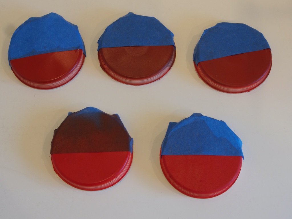
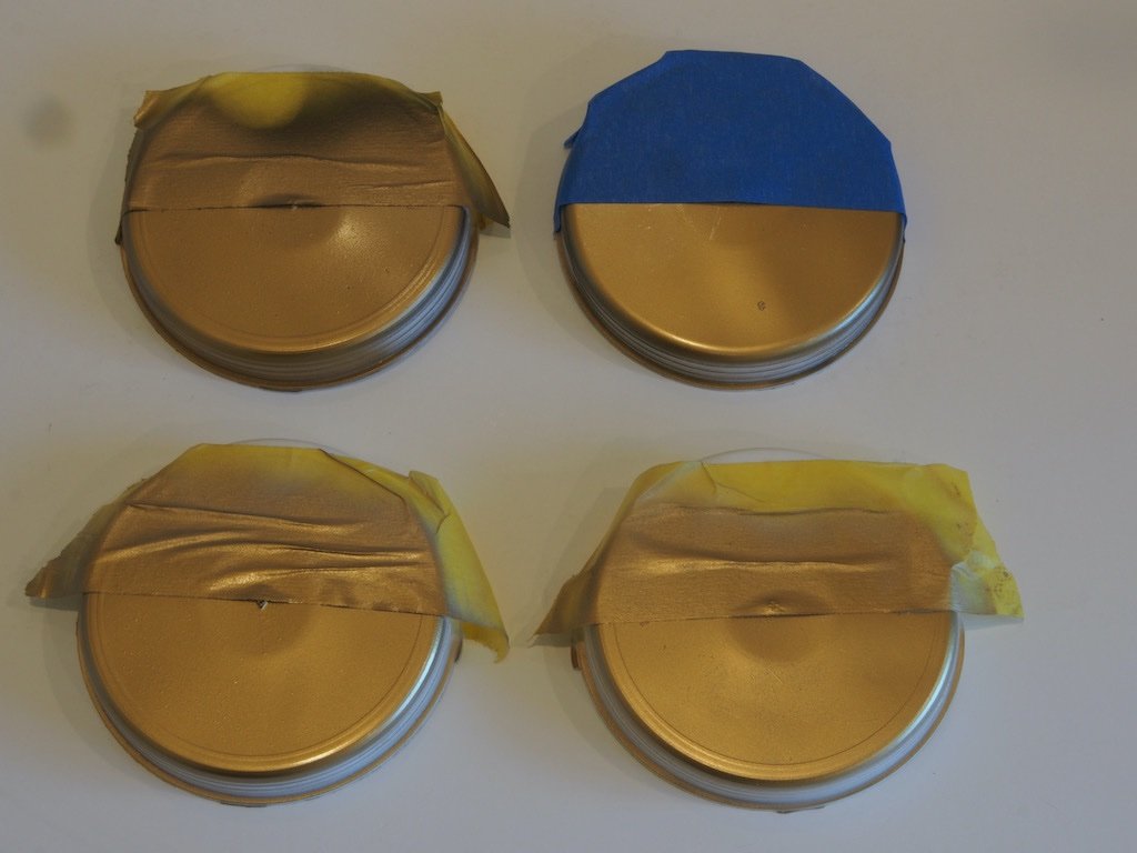
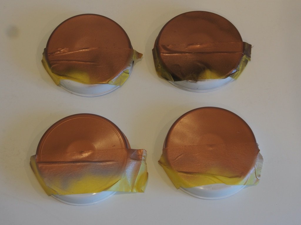
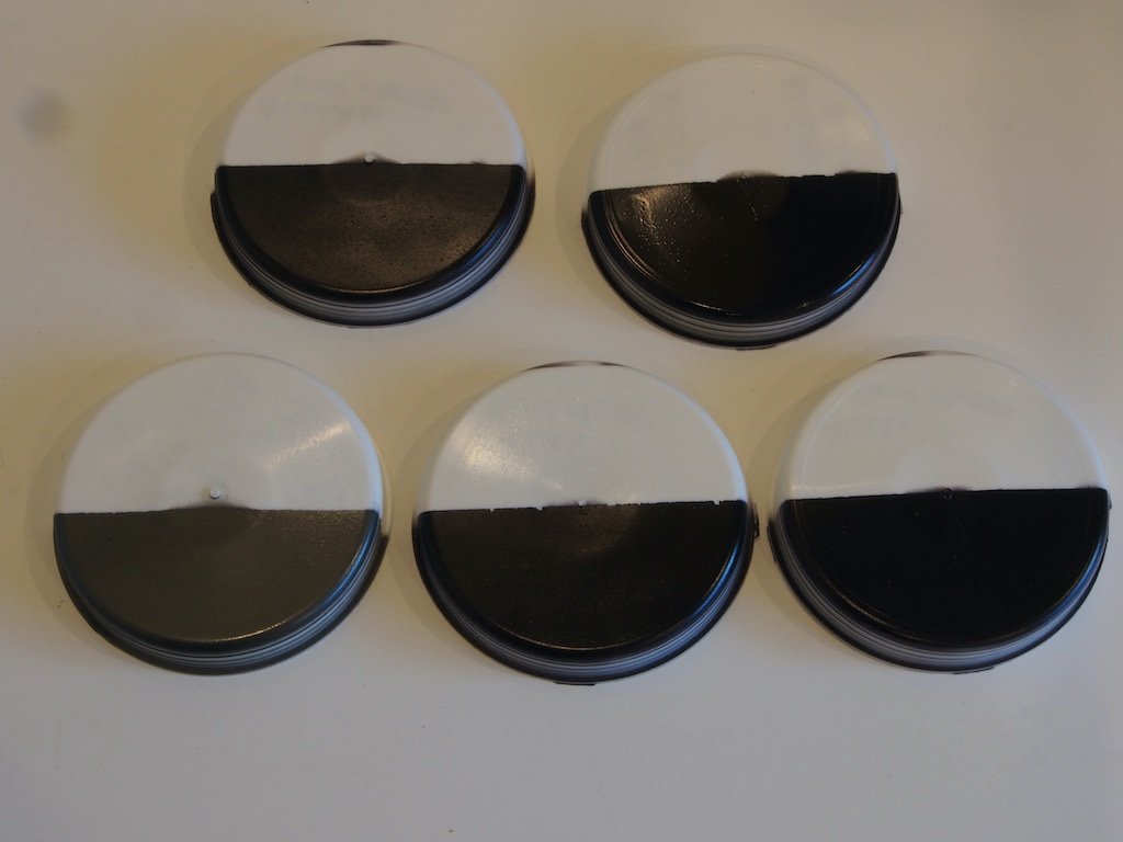
It's been a while since my last post. Not because there has been no progress but because I have been waylaid doing some Paint trials... Paint Trials The instructions call for the use of Krylon Foil Paints. This is particularly important for the appearance of the (simulated) Brass and Copper parts. Unfortunately, this range of Krylon paints is not available in Australia. I therefore decided that it would be sensible to do a series of trials to find a paint solution with which I would be happy. I initially tried the Krylon metal finish range but quickly decided that these gave nothing like the finish of the foil version of these paints. I had some previous experience with the Vallejo Metal Colour range but was concerned about the durability of these, being an alcohol-based acrylic. I spent some time researching options on the internet and watching a bunch of YouTube videos. The first conclusion I came to, was that there is a lot of crap and misinformation out there, posted by people who really don’t know what they are talking about. The good news is that I found a few whose opinions and advice I felt I could trust. The next conclusion I came to was that I wanted to try Lacquer paints. It seemed to me that they would give me the durability I sought while also being quite easy to airbrush. The only downside of Lacquers is that they contain “nasty” stuff. Given that one should really wear a respirator and use a spray booth even when spraying acrylics, it didn’t seem to me that this was a big deal (as long as I managed not to stink the rest of the house out). One big tip I picked up from YouTube is that you can use ordinary hardware store generic Lacquer Thinners for cleaning up. It can also be used for cleaning up after using acrylics if you wish to avoid confusion when using different paint types – one cleaner to rule them all. For thinning though, a branded Thinner such as Mr Hobby Levelling Thinner is recommended (if needed). For metal colours, I decided to give the Alclad range a try. They have quite a line-up in their range but again availability was to prove an issue. I would have liked to try their colour “Polished Brass” but nowhere in Australia seemed to have it in stock. Instead, I went with their “Pale Gold”. I also bought some of their Copper and Gun Metal. These all come pre-thinned and airbrush ready straight from the bottle. For the red painted sections, I decided to give Zero paints a go as I plan to use these for my next Pocher car model (in due course). These also come pre-thinned ready for airbrushing straight from the bottle. There is only one importer of these paints in Australia, and once again availability has been challenging. I did manage to find a colour called “Fire Engine Red”. It is supposed to be an exact match for a Mercedes Benz 300SL. I figured with a name like that, it would have to be a good choice for a fire engine. Then came the choice of primers. If you thought that it didn’t matter what colour primer you use, then think again! It’s usually a good bet to match the primer from the same brand as your colour coat – usually…. My previous experience using Metal Colours (Vallejo) was that they require a Gloss Black primer. So I ordered the Alclad Gloss Black Base when I ordered their other paints. Turns out that this is only required for their “high shine” range. For the “standard” metal colours, the instructions on the bottle say to use either their white, grey, or black (standard) primers. More testing to do. The good news is that the instructions also note that no clear coat is required to seal these and that they may be buffed with a micro-mesh cloth for a greater shine – just what I was looking for. Here are some test swatches of the Pale Gold using white, grey, black, and gloss black primers (no buffing here). It’s hard to tell from the photo, but the bottom left proved to be my favourite. It’s on a white primer, although at this stage that’s a Tamiya white primer (I’m still waiting on the Alclad one). And here are the same tests with the Copper. This was a close call between the white and grey primer, so to keep it simple I’ll stick with white. The gloss black (top right) was a long way last. The only Alclad metal that I didn’t like was the Gun Metal. Regardless of the primer used, it just looked black to the naked eye. So I decided to go with my Vallejo Gun Metal (bottom left in the picture) as there are very few parts that use this colour. When it came to the Red paint, I was really surprised at the difference the primers made. I was also really disappointed with the Zero white primer. I had been warned by one of my YouTube videos that the Zero white primer laid down “hairy” and that’s exactly what it did, giving quite a rough texture. I tried the red over Zero White, Tamiya White, Zero Light Grey, Stynylrez Grey (slightly darker than Zero), and Zero Red Oxide. Here are the results. The Greys and Red Oxide are along the top, the two whites are on the bottom (Tamiya white on the left, Zero on the right). The differences look much greater in real life. I was quite surprised that even the light grey primer gave a very dark and dull red. Only the white gave the brightness of colour I was after, although it did need more coats to gain the required depth of colour. This will eventually have a satin clear coat over the top. Following the paint trials, I am awaiting a further order of primers, including both Alclad and Stynylrez. I really liked the way the Alclad sprayed for both the primers and the metal colours. I’d heard good things about the Stynylrez, so wanted to try it too. So far, I have only tried the Grey. It is much, much thicker than any other primer I’ve used and the instructions on the bottle say to use a 0.5mm or larger needle when spraying it and to use a higher pressure (20-30 psi). That said, it does self-level beautifully, despite its initial appearance when first sprayed. I particularly want to do a side-by-side comparison of the Alclad and Stynylrez white primers under the Zero Red colour coat. More trials to come….
-
I’m in too. Should be an interesting build. I’ll join Mark at the bar for this.
