gjdale
-
Posts
4,894 -
Joined
-
Last visited
Content Type
Profiles
Forums
Gallery
Events
Everything posted by gjdale
-
 Terrific work, as always, Glenn. Like so many others, I am getting genuine pleasure from reading your weekly updates. Thanks for sharing and for your informative descriptions.
 -
Congratulations Alexandru, what a magnificent build and some really stunning pictures on your website!
-
Your base/case looks great Bob. Thanks for sharing your techniques - there's a lot to take away from your mini-tutorial.
- 277 replies
-
- 3
-

-
- model shipways
- 18th century longboat
- (and 1 more)
-
Another interesting project Slog. Think I'll pull up a chair as well.
- 244 replies
-
- 5
-
-
- borodino
- dom bumagi
- (and 1 more)
-
I haven't got that far yet, but plan on using the lit supplied stain. Everything I've read says it looks a bit orange when it goes on but after the resin us applied, it goes a very nice colour. I'm also using different timber for the cockpits and dashboard, where I'm using some Redheart, which will just receive a clear finish.
-
And Happy Birthday from me too Mark. I hope you get thoroughly spoiled for the day and receive many model building-related gifts!
-
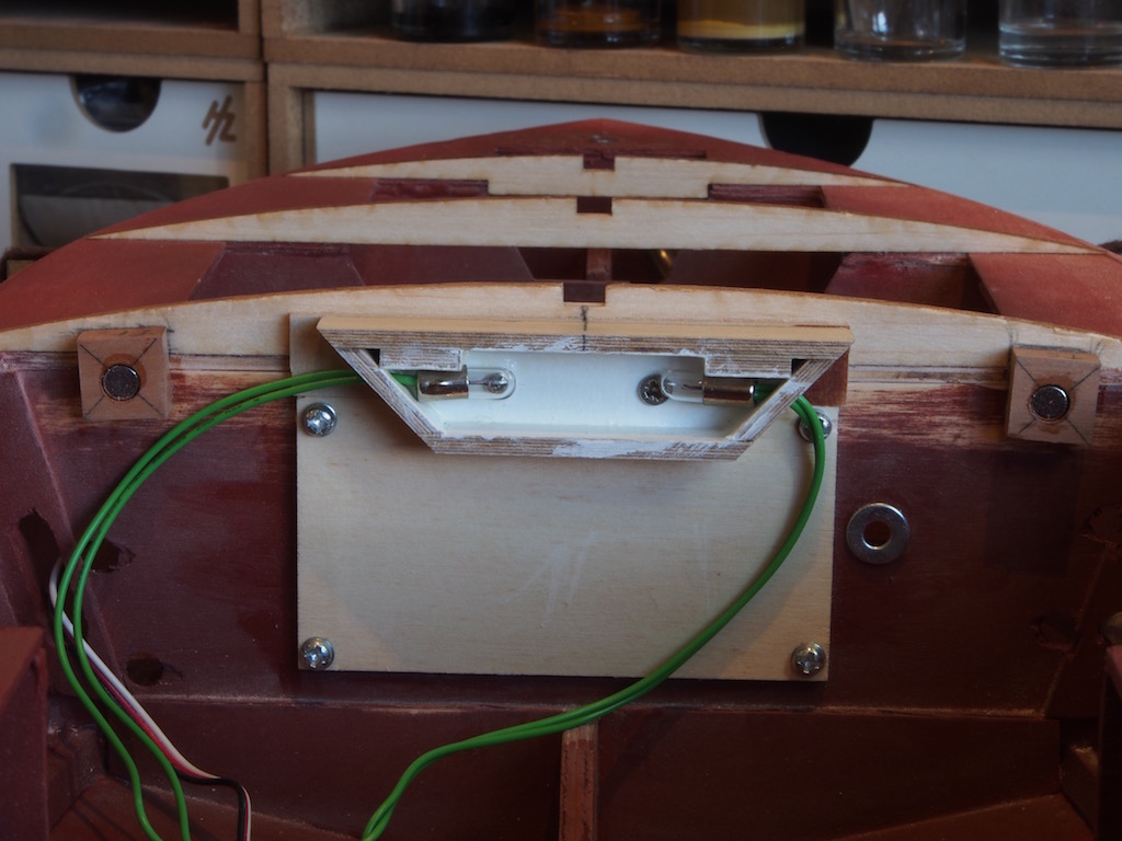
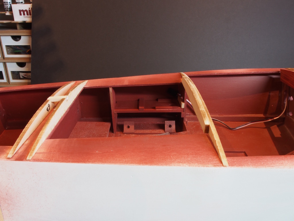
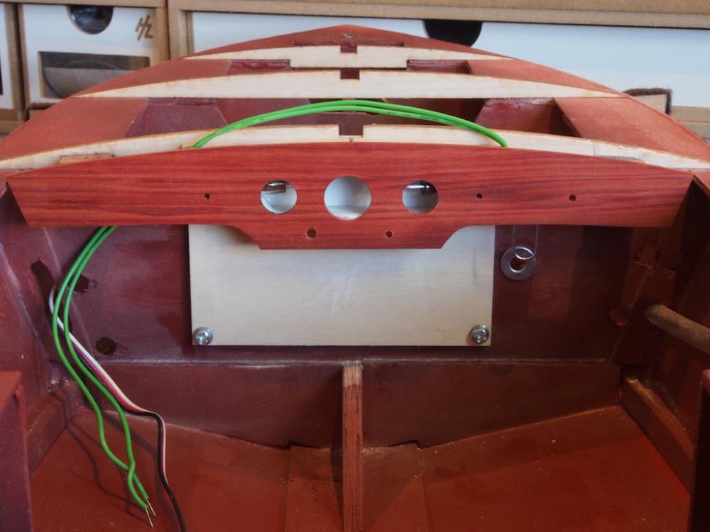
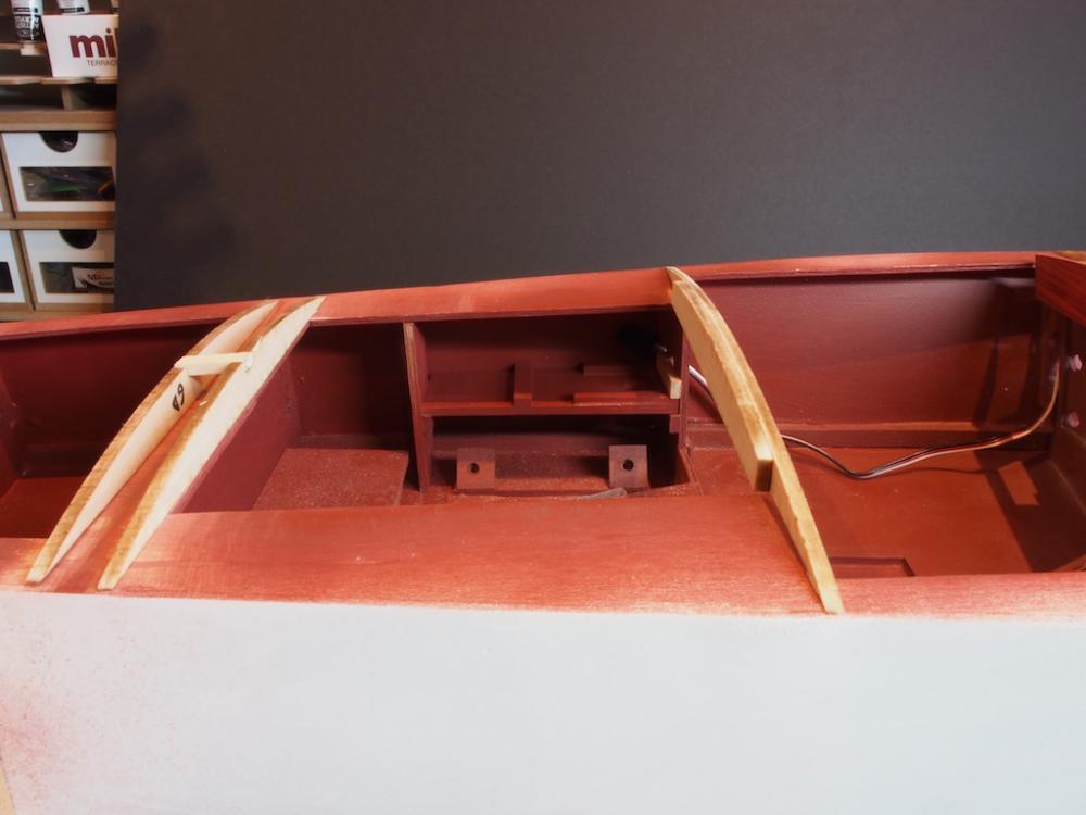
Dashboard and Lighting Having decided that I wanted to light the dashboard, I decided it would be a good idea to make it removable in case a light needed to be replaced down track. Rather than using screws or pins to hold the dash in place, I decided to use some rare earth magnets. Making up a light box was fairly simple, using some scrap pieces of ply and a cardboard backing. The light box was painted white and given a gloss finish to help reflect the light. Two 3v lights will be used as shown here. I also made the light box itself removable, although I did elect to use screws to secure this one. In the picture below, you can see the light box in place, and on either edge of the photo is a spacer block with a rare earth magnet epoxied in place. There is a matching pair on the mating face of the dashboard. I decided to replace the kit-supplied walnut dashboard with one made from some Redheart that I had left over from a previous build. This is to match the cockpit sides that will likewise be made from Redheart planks instead of the kit supplied plywood. I used the kit piece as a template to get the overall shape. I also used the supplied dashboard decal to locate the positions of the gauges and knobs/switches – although I added a couple of extra knobs based on some photos of the real boat. I have already made new instrument bezels (way back in January last year), and I have acquired some nice looking knobs/switches from MACK products. Here is a picture of the (empty) dashboard in place. It will be finished when the cockpit sides etc are done, but was needed now to ensure that the steering and light fittings would all work as planned. I have also installed all of the deck frames in preparation for closing up the decks with more Sintra sheeting. Here are a few shots of overall progress, including a couple showing the electronics housings temporarily in place. I’m still thinking about making these removable to make connections/replacements easier down track. Next up, the cockpit sides.....

- 339 replies
-
- 18
-
-
- dumas
- Chris-Craft
- (and 3 more)
-
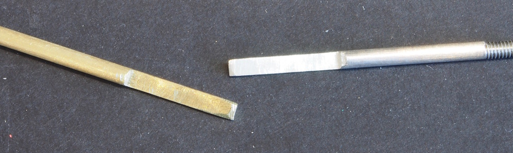
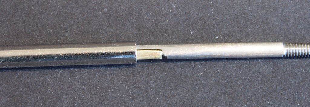
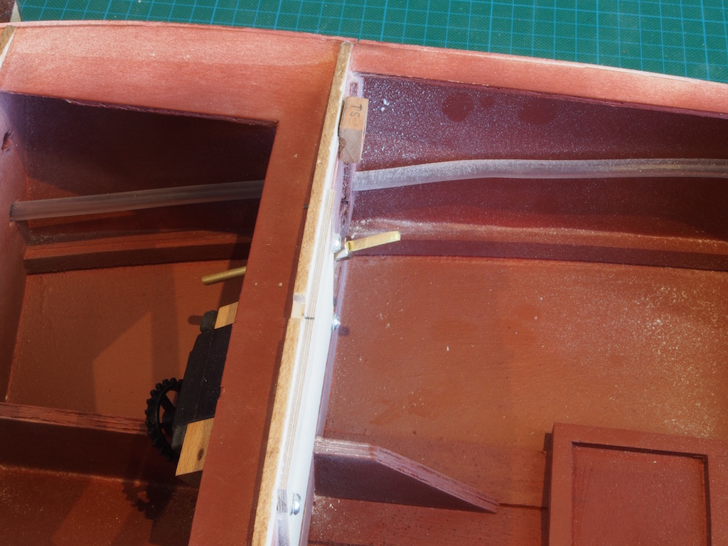
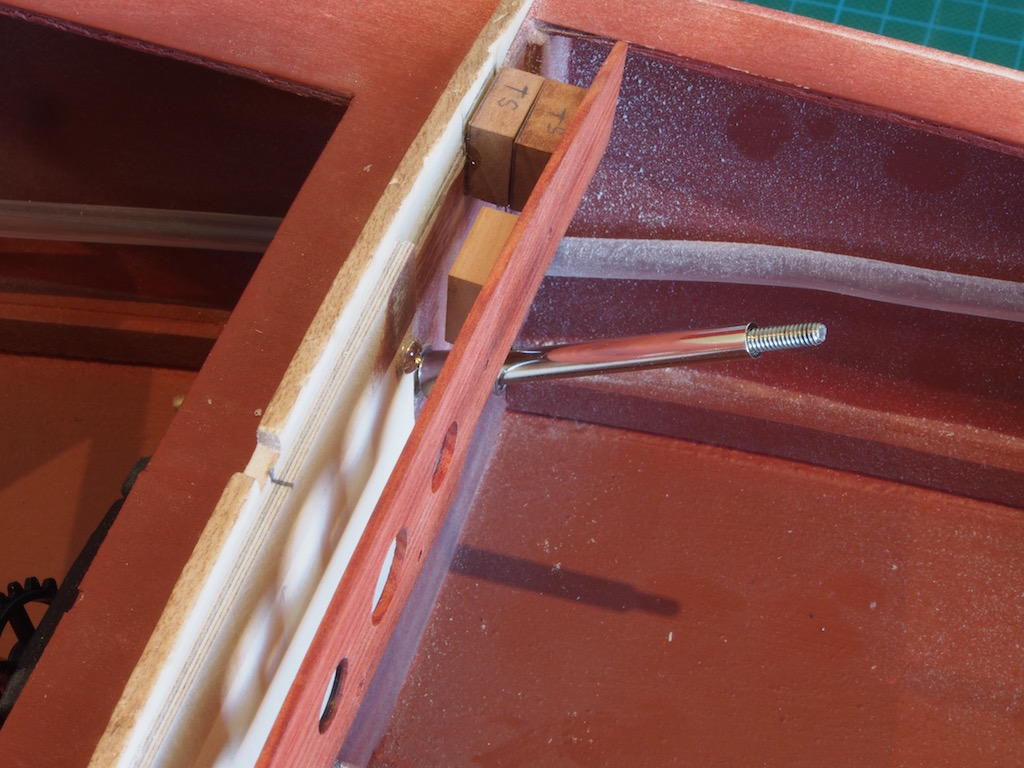
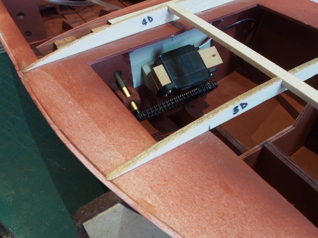
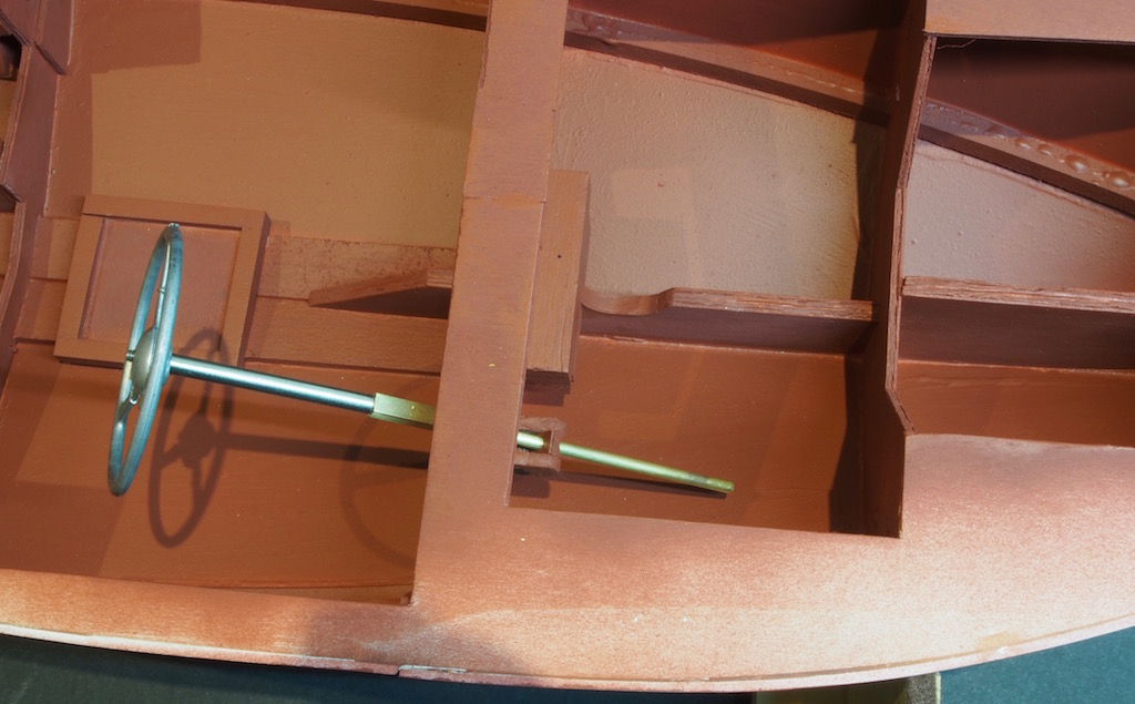
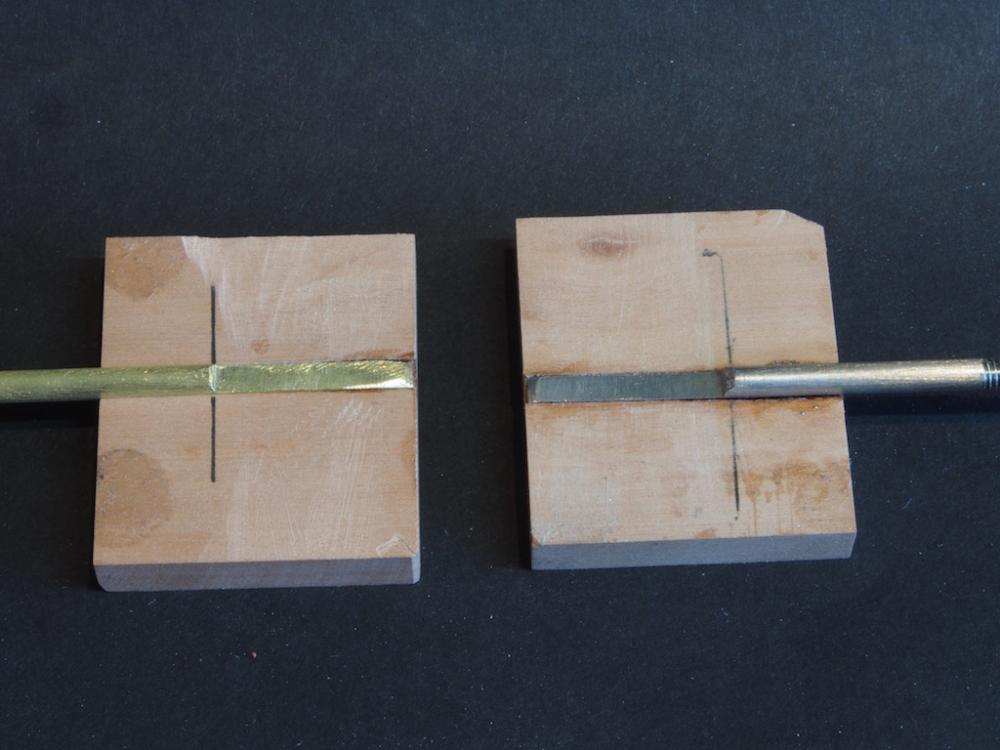
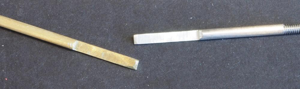
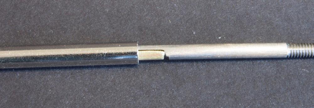
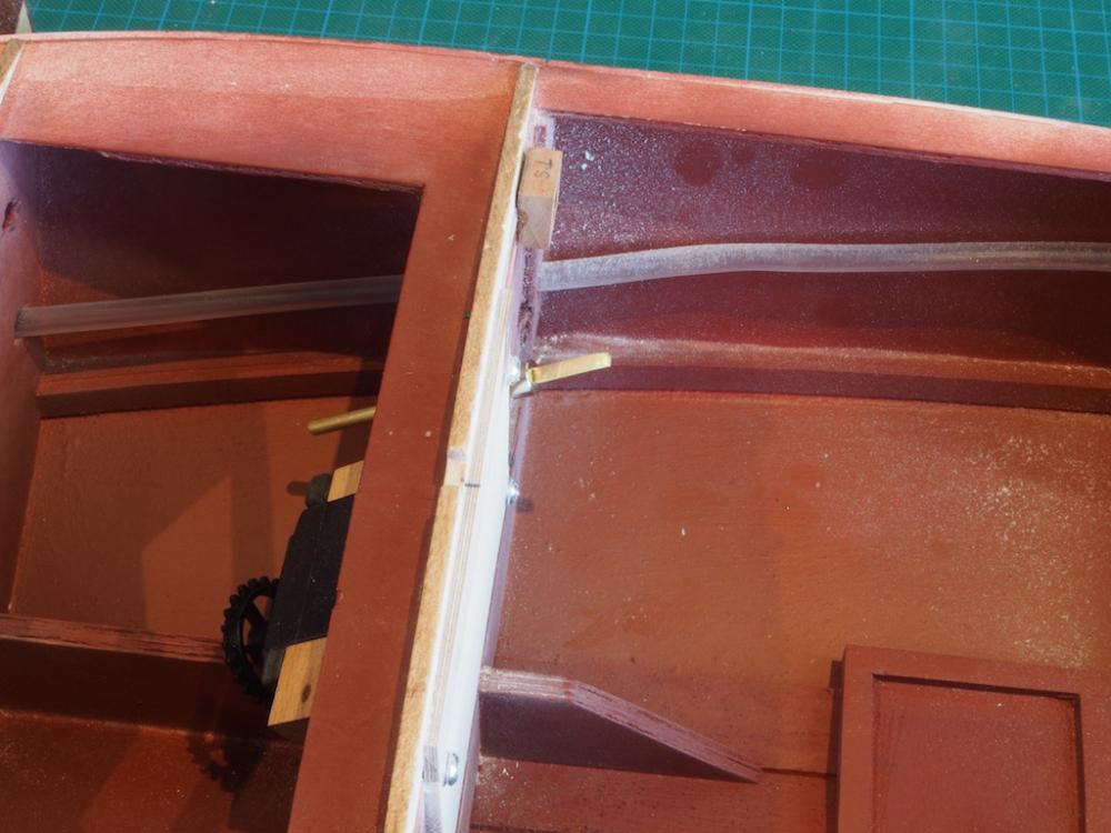
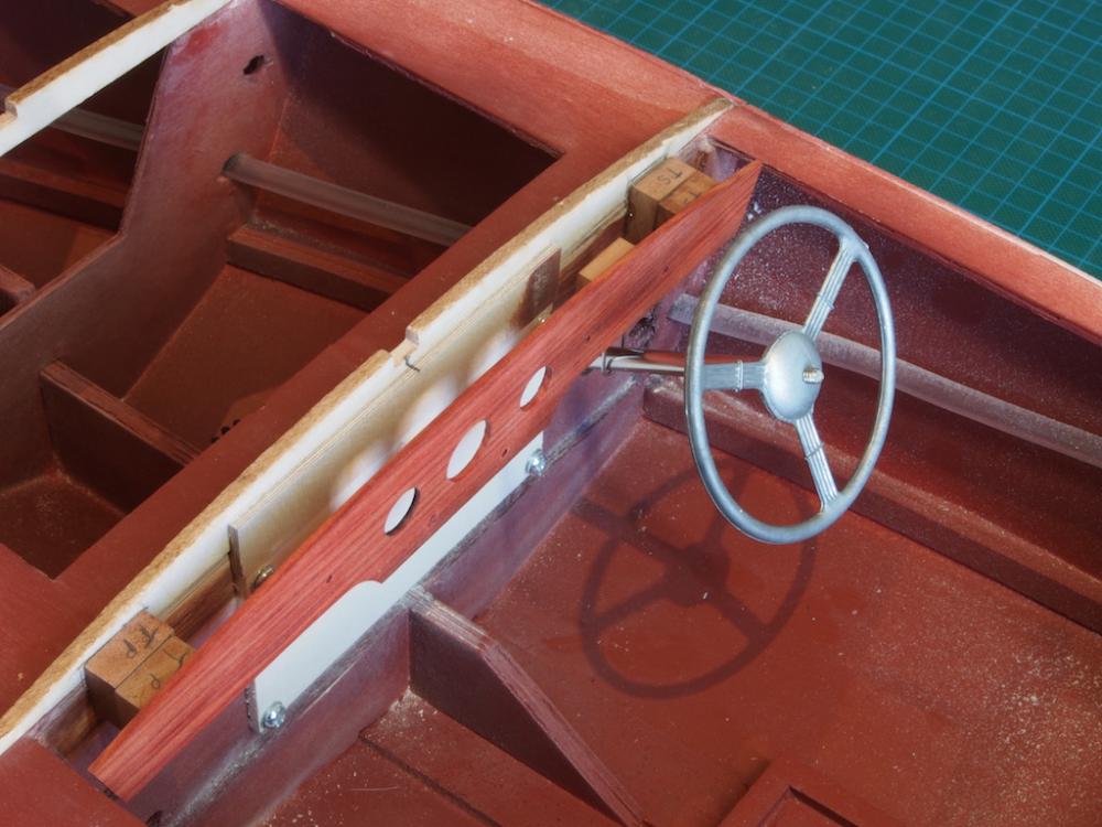
Thanks again everyone for the kind comments and all of the 'likes'. Steering Column Mk 2 The best laid plans….. When I did a test fit with the dashboard in place, it became obvious that my brilliant feat of engineering was not going to work. The joined section of square tubing was going to be too long to fit in the space available and shortening the joined section provided too much play in the joint. Back to the drawing board. After sleeping on the problem I decided on a different approach – one that I cannot take any credit for as I simply modified slightly an approach I’d seen taken by someone else. In the end, it was far simpler and took far less time, and best of all – it works! I started by making a couple of small jigs to hold the two sections of steering shaft rod. I did this by tack-gluing two pieces of scrap wood together and then drilling a 1/8” hole directly down the centre, along the join line. I then separated the pieces, glued the two shaft sections in place with CA glue, and filed a 20mm section half-way through each. The two shaft sections were then removed from the jig and cleaned up of glue residue: These two pieces are then able to interlock within the steering column tube, shown here with the joint just poking out for illustration. The lower half was then positioned in the boat, and held in place with a wheel collar. The removable dashboard (more about that later) was then fitted, the chrome steering column tube slipped in place, and the top steering shaft section inserted and mated. Finally, the steering wheel was screwed into place (remember that this is only for test purposes – a new wheel assembly will be made in due course). Once I was satisfied with the assembly, it was disassembled and the lower shaft was fitted with its sprocket and chain to the servo. This won’t be coming out again now! Continued next post...


- 339 replies
-
- 17
-
-
- dumas
- Chris-Craft
- (and 3 more)
-
You might want to consider replacing the motor mount blocks with something other than balsa. I used some scraps of pine for mine - just felt a little more secure for holding the mounting screws. I just noticed that in the two pics above, your steering column support appears on different sides - starboard side in the top pic, and port side on the bottom pic. The starboard side is correct.
-
Sorry to hear of the cumulative error problem Toni. However, it does nor detract from the beauty of your model in any way and I doubt that any of us would have noticed had you not told us. Red wine helps in these situations too!
-
Wow! She's looking just stunning Mobbsie. I love the extra little touches you've applied to make her uniquely yours.
- 129 replies
-
- 4
-
-
- armed launch
- panart
- (and 1 more)
-
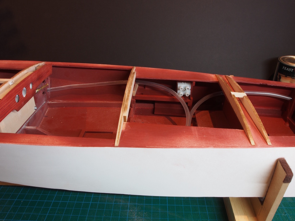
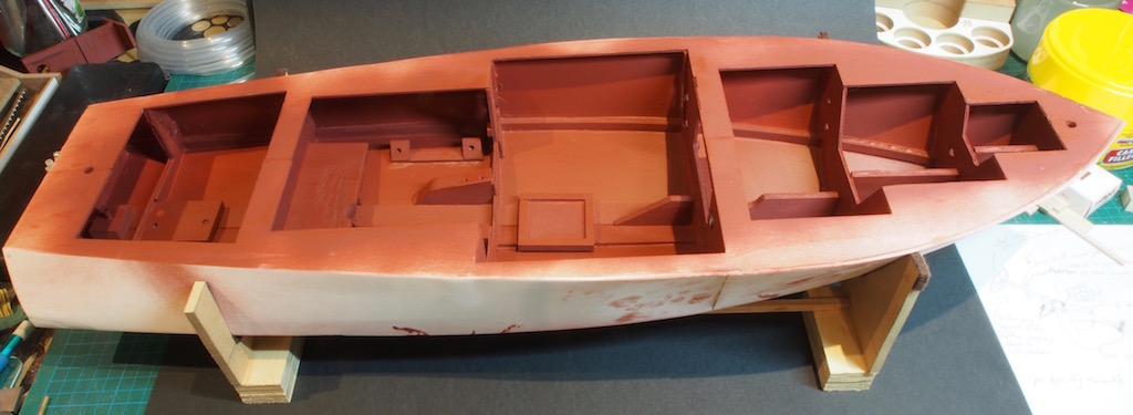
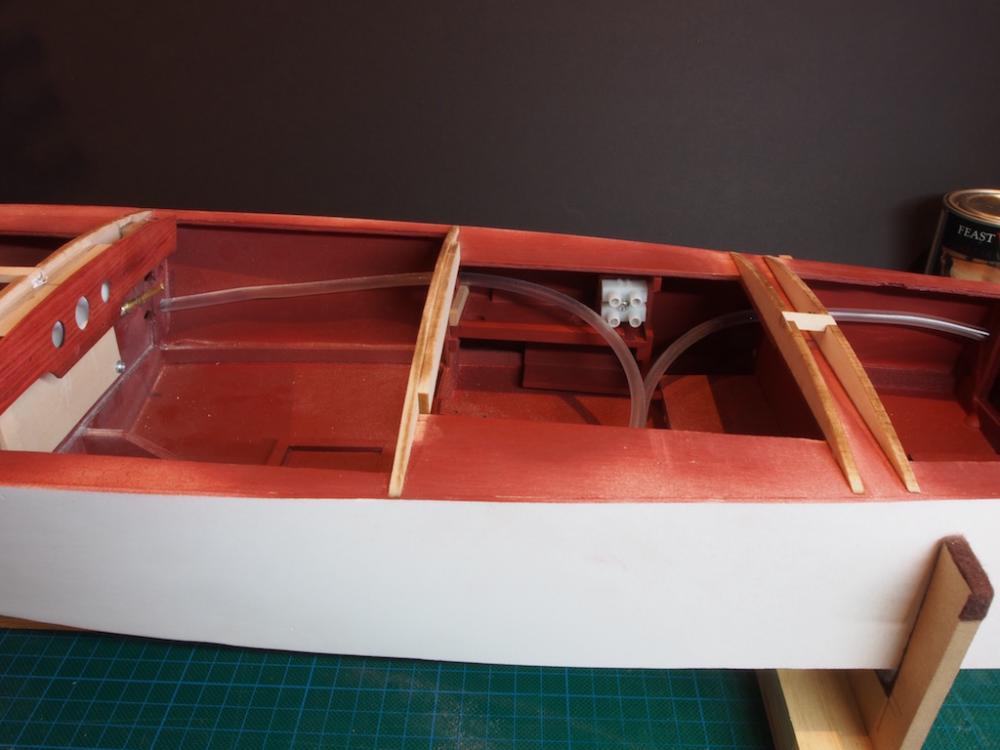
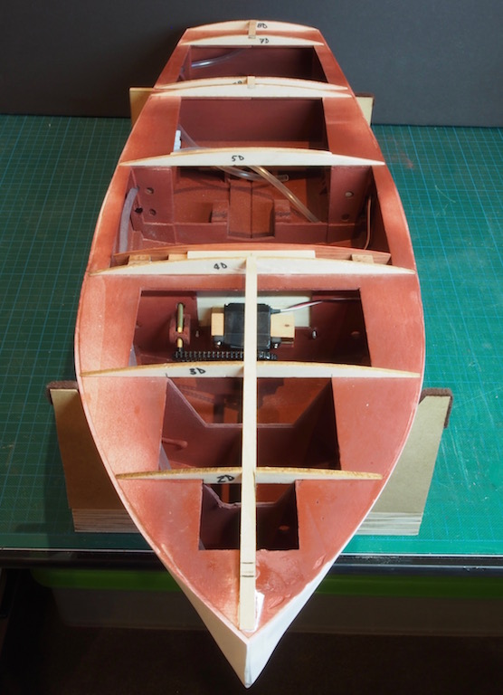
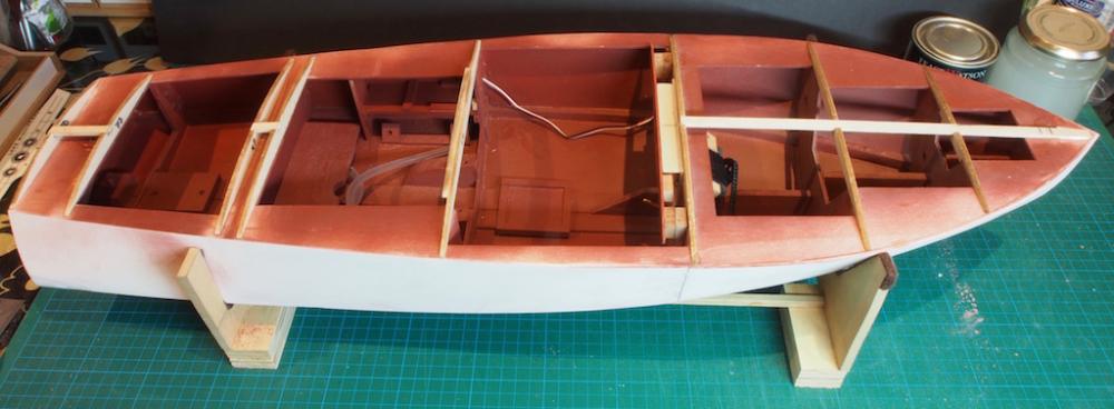
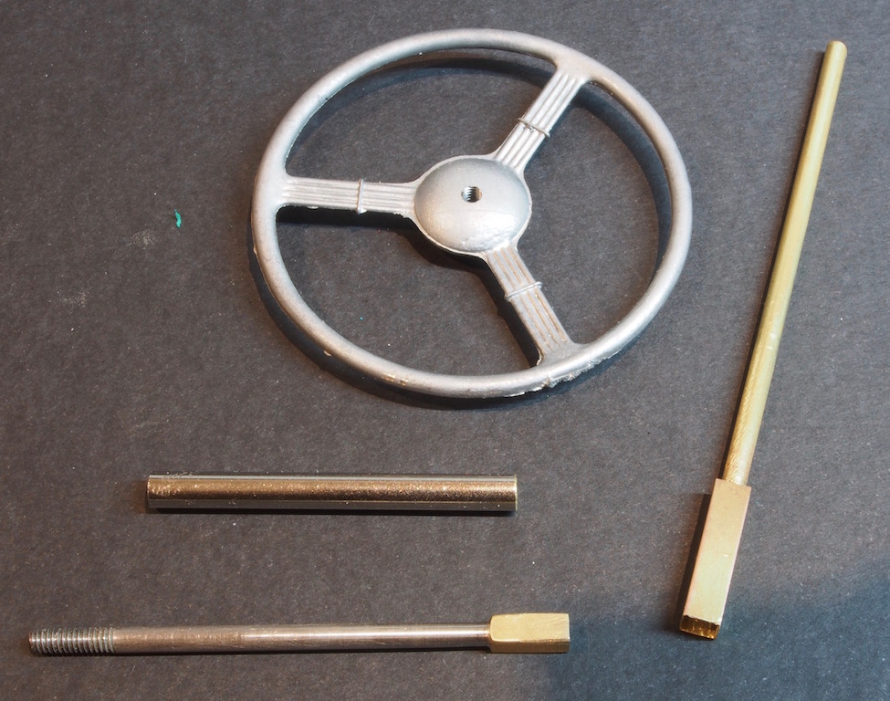
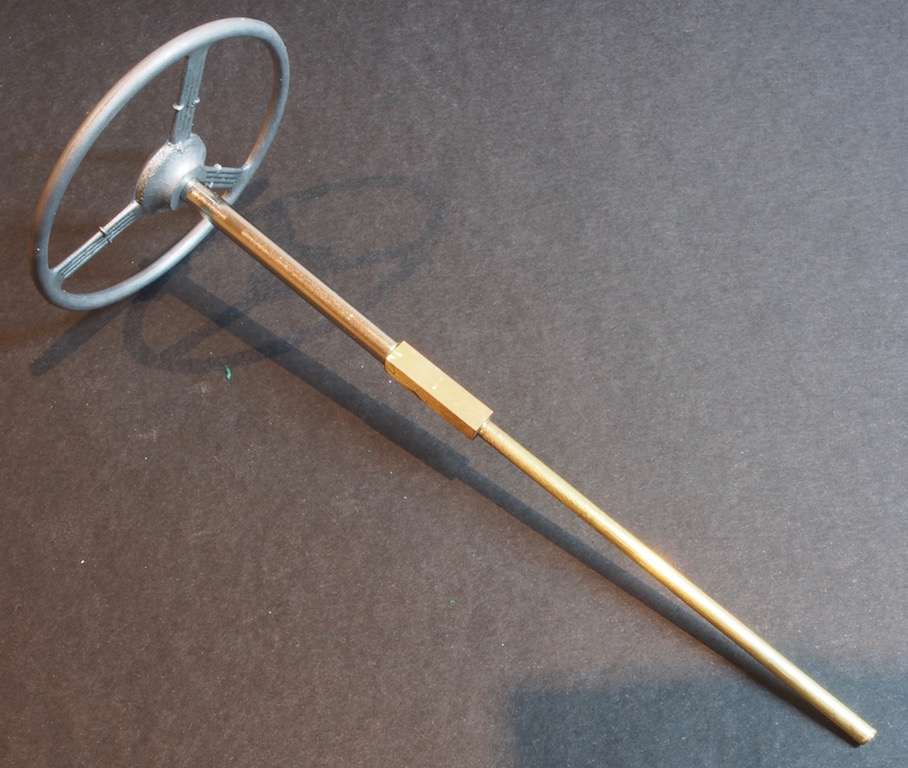
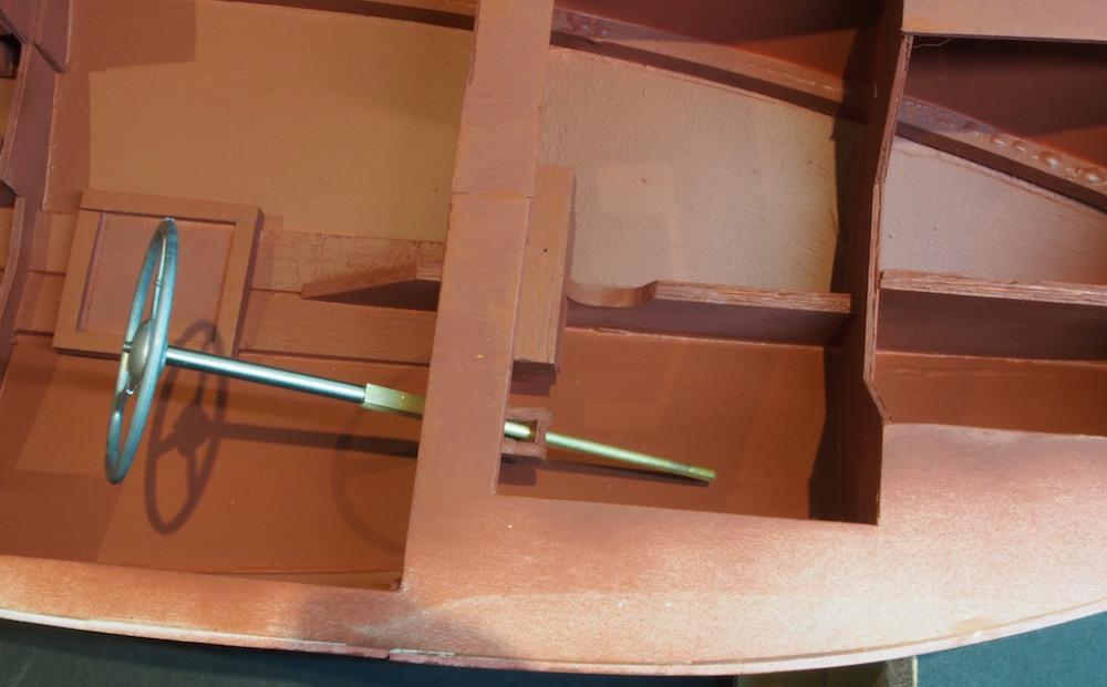
Thanks everyone for looking in, your kind words, and valued advice. I have been super busy with work the last couple of weeks, so not much time in the shipyard until this weekend. Once I was happy that all the glue joints were going to hold, I painted the whole of the interior with a coat of epoxy finishing resin, thinned to the consistency of paint with Methylated Spirits (denatured alcohol for my American friends). Several days later, a coat of red oxide primer was sprayed over the entire interior, giving the whole boat an immediate face-lift: Steering Column The next job was to finalise the design and construction of the steering column. Because of the set-up I am using to make the steering wheel turn when the rudder is turned, it will be necessary to install this equipment before closing up the hull. However, if I installed the steering column as a single piece, I could see it causing problems during the remainder of the build. I needed to come up with a design that would see the lower half of the steering column permanently mounted, while the upper half would be removable. It would also have to engage in such a way that the turning moment was transferred from lower half to upper half. My solution was to make use of the fact that brass tubing is manufactured in such a way that each size telescopes inside the next size up. Both halves of the steering column are made from 1/8” diameter rod (brass on the lower half and stainless steel on the upper half). I then soldered a 1/8” square section brass tube, 10mm long to the ends to be joined. I then took a piece of 5/32” square section brass tube, 20mm long and soldered this over the lower half, such that the previously soldered 1/8” section fitted inside for half the length. This then created a mating “socket" for the upper half. The top end of the upper half was then threaded (using my newly acquired, oh so expensive 5-40 HSS Die, and my home-made die holder). This then screws into the Steering wheel, which had a 5-40 thread tapped through the centre. This is a temporary arrangement as I plan to remake the steering wheel in brass later on, but is sufficient to prove the concept of the removable steering shaft. The upper half of the steering column also has an outer sleeve of polished chrome (kit supplied). Here is a shot of all the components (minus the drive gear, which will be fiited on mounting permanently): And here is a shot of how it all goes together: And finally, a shot of it test-mounted in the boat: I have also installed some plastic tubing to help with electrical cable runs (no pics yet). The next job will be to complete the dashboard as I need to work out the lighting and run the wiring for it. I plan to make the dashboard removable as well, in case a light fitting needs replacing.

- 339 replies
-
- 16
-
-
- dumas
- Chris-Craft
- (and 3 more)
-
Hamilton, There is a tutorial on silver soldering in the NRG database: http://modelshipworldforum.com/resources/materials_and_tools/SilverSolderTutorial.pdf Hope this helps.
-
In Pat's book, he recommends using Milliput (a two part epoxy putty). I'm going to use that but haven't got that far yet. Pat recommends not using Bondo as it sometimes has difficulty adhering to plastics.
-
Congratulations Danny, another masterpiece completed. So what's next? Enquiring minds want to know.
-
I think that's a wise decision to wait for the book Paul - it's got some great advice, especially for those of us new to this form of modelling. It also suggests a few different build sequences to those described in the instructions. I've certainly found it invaluable so far. Interesting comment about fibreglass/resin reacting with the Sintra. I don't recall reading that in the instructions but will have another check. There was certainly no reaction between the resin and the Sintra on the inside of the hull. I guess it always pays to do a test on some scrap material before diving in with the finished product!
-
Having read the same comments about the Sintra (plastic) opening up at the seams, I'm planning to fibreglass the exterior of the bottom as well. The instructions claim you don't need to, but I think I'll err on the side of caution with this. And I have also painted the interior with a diluted coat of finishing resin - finishing resin diluted with what I believe you call denatured alcohol in the US, or Methylated Spirits (Metho) over here. The advice from the guy in my local hobby shop was to add just enough Metho to make the resin the consistency of paint. I had no problem following his advice, but haven't given it a water-tight test yet.
-
I'm new to this myself, but the advice I received was to go for a 2.4Ghz radio system (they seem to be the "standard" these days). Unless you're planning on adding "extras" a simple two channel, or three channel system will suffice. (Three channels will allow you to add lighting if you want). A simple "pistol grip" controller, like those used for RC cars, is great for this basic setup. With your Electronic Speed Control (ESC), if you ensure it has BEC (Battery Eliminating Circuit) it will save you having to run a separate battery for the Receiver (it will then be powered by the main battery). There is good basic "how to" guide on electrical stuff over at the rcgroups forum: http://www.rcgroups.com/forums/showthread.php?t=783582 Hope this helps.
-
That was a bit of bad luck Jerry, but a nice recovery as we'd expect from you!
-
Hi Trasboat (do you have a real name?), I'm building this same kit, so we might be able to help each other out along the way. Lots of "firsts" for me on this one too! I'm a very slow builder (lots of other demands on my time), so it won't take long for you to catch up and overtake me. There's a link to my build log in my signature block below if you're interested. I've learned a few lessons already!
-
Glad to hear it was just a trick of the camera Jerry.