gjdale
-
Posts
4,897 -
Joined
-
Last visited
Content Type
Profiles
Forums
Gallery
Events
Everything posted by gjdale
-
 That was a bit of bad luck Jerry, but a nice recovery as we'd expect from you!
 -
Hi Trasboat (do you have a real name?), I'm building this same kit, so we might be able to help each other out along the way. Lots of "firsts" for me on this one too! I'm a very slow builder (lots of other demands on my time), so it won't take long for you to catch up and overtake me. There's a link to my build log in my signature block below if you're interested. I've learned a few lessons already!
-
Glad to hear it was just a trick of the camera Jerry.
-
Could be a trick of the camera Jerry, but Elijah is right - the keel definitely appears to have a bend in the photos above.
-
I'm glad to see you decided to start a log on your Bluenose build Jerry, and very pleased to hear of the improvement in your medical condition. I'll tag along too as a Bluenose of some description is on my "one of these days" list. Just remember to take your time and enjoy the journey!
-
There is a great tutorial over on the rcgroups website: http://www.rcgroups.com/forums/showthread.php?t=329811 Which Dumas kit are you building?
-
Great news Aydin. Customer service like that is hard to find these days. I'm sure they now have one more loyal customer, and through your recommends, likely several more. Good to hear the wrist is healing - enjoy the football vacation.
- 414 replies
-
- 4
-

-
- riva aquarama
- amati
- (and 2 more)
-
Thanks Thomas, Tom - thanks for stopping by. Yes, there is a little room for adjustment and the photo might not show it very well, but the aim is to have the rudder as a continuation of the line of the prop shaft. In the end, I think the aft lower edge of the rudder will be just below the prop blades. I'll still be trying to avoid any form of grounding or collision! As the saying goes, a collision at sea can ruin your entire day!
- 339 replies
-
- 6
-
-
- dumas
- Chris-Craft
- (and 3 more)
-
Thanks Mark, you're absolutely right - had it been wood, it would have been a no-brainer. Not being used to working with plastic, the mind just wasn't clutched in to the same wavelength. Gerhard - there are more scratches and 'divots' than you can see in the photos. The whole hull will receive a skim coat of auto body filler, which will also address all of those little imperfections (and the not-so-little ones as well) The aim will be to have a near-perfect smooth and faired hull before planking proper begins.
- 339 replies
-
- 6
-
-
- dumas
- Chris-Craft
- (and 3 more)
-
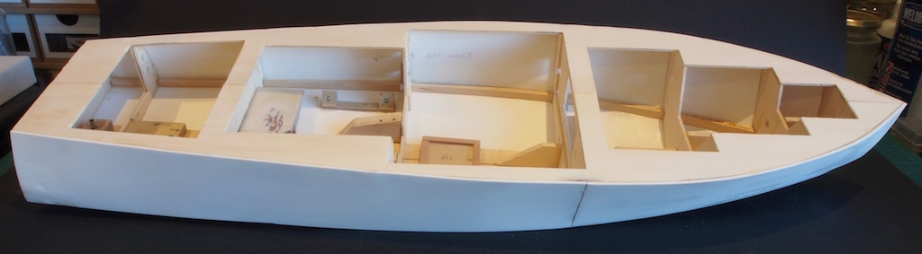
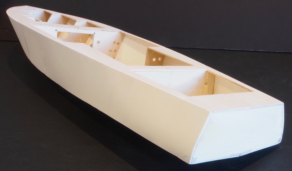
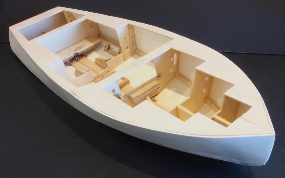
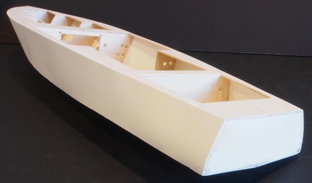
Thanks for all the kind comments and the 'likes' folks. At last, I have a bit of an update... Side Underplanking The last couple of weekends have been spent doing battle with the underplanking on the sides of the hull. Similar to the bottom, the side underplanking uses four sheets of Sintra (expanded core PVC). There are two sheets per side, with one sheet running from Frame 4 aft, and the other from Frame 4 forward. The aft sheets are installed first, and then the forward sheets. The forward sheets need a little shaping to fit snugly in the overhang of the bottom sheet, and they also overlap at the stem. The instructions say to use CA glue to attach these four sheets, beginning with the aft sheet on each side. They offer no further advice about coping with the compound curves in each direction. Even Pat Matthews’ excellent book offers little further advice, although I was relieved to read that even he found installing these panels “just a bit awkward”. CA glue and I just don’t seem to get along. I have become sensitised to it, and it doesn’t take much exposure to give me flu-like symptoms for the next three days, even with the so-called ‘odourless’ varieties. When I do use it, I wear an appropriate mask to try and prevent the symptoms. Add to that, I must be the only person in the world who has trouble getting CA glue to hold. On my first attempt to glue one of the aft panels, it just popped right off again, even after using a liberal amount of ‘kicker’. So, I decided to do this job using 5-minute epoxy instead. The next issue was trying to clamp the pieces in place while the glue set and cured. There are so many compound curves on the hull, finding a way to clamp successfully takes a lot of thought and much trial and error. I ended up gluing just along the bottom edge and allowing that to fully cure before bending it to shape around the hull and gluing the top edge, sometimes in two or more sections. I even managed to snap one of the aft panels using this method, but a bit of extra epoxy and some additional sanding later on recovered that oops. The front panels were even more fun and clamping all but impossible. However, I persevered and found a way. Just as I thought I was done, the epoxy gave way and the last front panel sprang away again. After much cursing, I was chatting on Skype with Mobbsie and he asked me if I could clamp the piece in place without glue and then apply heat to relieve the stress in the plastic and hence prevent it from trying to spring back. Doh! The obvious solution was right under my nose, but until I had that conversation, it hadn’t occurred to me. So, I did exactly that. I clamped the piece in place and gently applied hot air from my heat gun. In no time at all the piece had taken the basic shape and I was able to glue it up again without it trying to fight me all the way. Thanks Mobbsie! But the fun wasn’t over yet. As I was sanding the excess plastic and glue, both forward panels separated again at the bow. A few more rude words, a quick application from the heat gun, and yet more epoxy, and we were back in business. Once the glue had cured, I finished removing most of the excess plastic using a sanding drum in the Dremel rotary tool, and then finishing with a hand sanding block to achieve a flush upper surface, a sharp chine, and a reasonable looking stem. A couple of balsa filler blocks are required at the lower end of the stem, and these are easily sanded to shape when cleaning up the rest. There a few 'divots' in the plastic sheeting from where I was a little over-zealous with the sanding drum, but these will be filled and sanded again before the outer planking is applied. In conclusion, the job would have been a whole lot easier if I had thought of using the heat gun to assist the shaping in the first instance. It would have been nice if the instructions had included that hint, but perhaps there was an assumption of knowledge there. Not much to show for two weekends worth of work, but here are a couple of pictures to bring the log up to date. The next task will be to run some tubing for the wiring for the lights, and then give the interior a coat of Finish Resin as a sealer. That may be a little while coming as I have a pretty busy week and weekend ahead.

- 339 replies
-
- 14
-
-
- dumas
- Chris-Craft
- (and 3 more)
-
Sorry to hear of your strained wrist Aydin - best wishes for a speedy recovery. I too have missed your updates.
- 414 replies
-
- 3
-
-
- riva aquarama
- amati
- (and 2 more)
-
I'm not normally a plastics kinda guy, but this looks like a really interesting build Greg so I think I'll pull up a chair and follow along too.
- 342 replies
-
- 5
-
-
- dreadnought
- zvezda
- (and 2 more)
-
Ah, the offer of Sacher Torte and coffee! Okay, I'm in then! Looks like this will be an interesting build Gerhard, and the finished boat will be a real beauty. Your Admiral has good taste and I'm sure will be delighted to see you starting this.
- 72 replies
-
- 5
-
-
- bootlegger
- speedboat
- (and 1 more)
-
Nice to see an update Mobbsie. She's looking might fine and the inclusion of some nicer timber really does show her off nicely. Looking forward to the next update.
- 129 replies
-
- 7
-
-
- armed launch
- panart
- (and 1 more)
-
"Outstanding" hardly seems to do justice to your work Nils. "Breath-taking" comes a little closer..... Just love the double laundry peg clamp - you may have just started a whole new cottage industry here!
- 2,625 replies
-
- 7
-
-
- kaiser wilhelm der grosse
- passenger steamer
- (and 1 more)
-
THE 74-GUN SHIP by Jeronimo
gjdale replied to Jeronimo's topic in - Build logs for subjects built 1751 - 1800
Wonderful! -
Great to hear of the success of the surgery Jerry. Good luck to the both of you with your next builds.
-
Hi Doc, Good to hear from you - your AVS is looking splendid! In answer to your question, my red heart went quite dark as soon as I applied WOP to it. I would say it is a deep reddish-brown. It still looks much the same as in the finishing photos posted here - I think that the colour in the photos is a pretty accurate representation (depending on your monitor, of course). When will you be starting your own BV Cross-Section?
- 456 replies
-
- 3
-
-
- finished
- bomb ketch
- (and 2 more)
-
Fabulous Danny, as always! Hopefully, Australia Post won't let us down and you'll have the extra rope in a couple of days.
-
Did someone say popcorn? I'm in. Where's Mark with the bar? Looking forward to following your next adventure Sjors.