HOLIDAY DONATION DRIVE - SUPPORT MSW - DO YOUR PART TO KEEP THIS GREAT FORUM GOING! (Only 27 donations so far out of 49,000 members - C'mon guys!)
×


FriedClams
-
Posts
1,368 -
Joined
-
Last visited
Content Type
Profiles
Forums
Gallery
Events
Everything posted by FriedClams
-
 That's a nice before and after shot John. Its good to know I'm not the only one who has to go back and tidy up. She's progressing nicely and looking very fine. Gary
 -
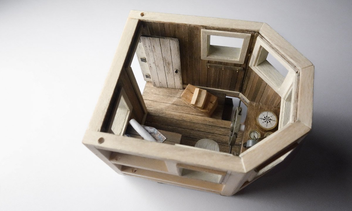
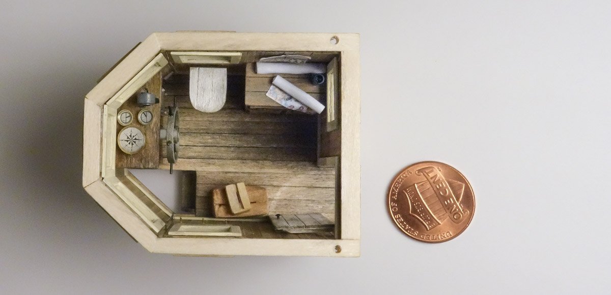
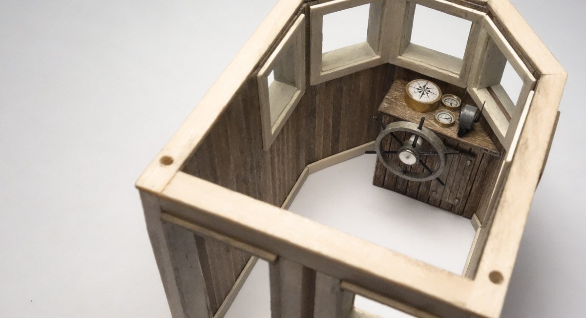
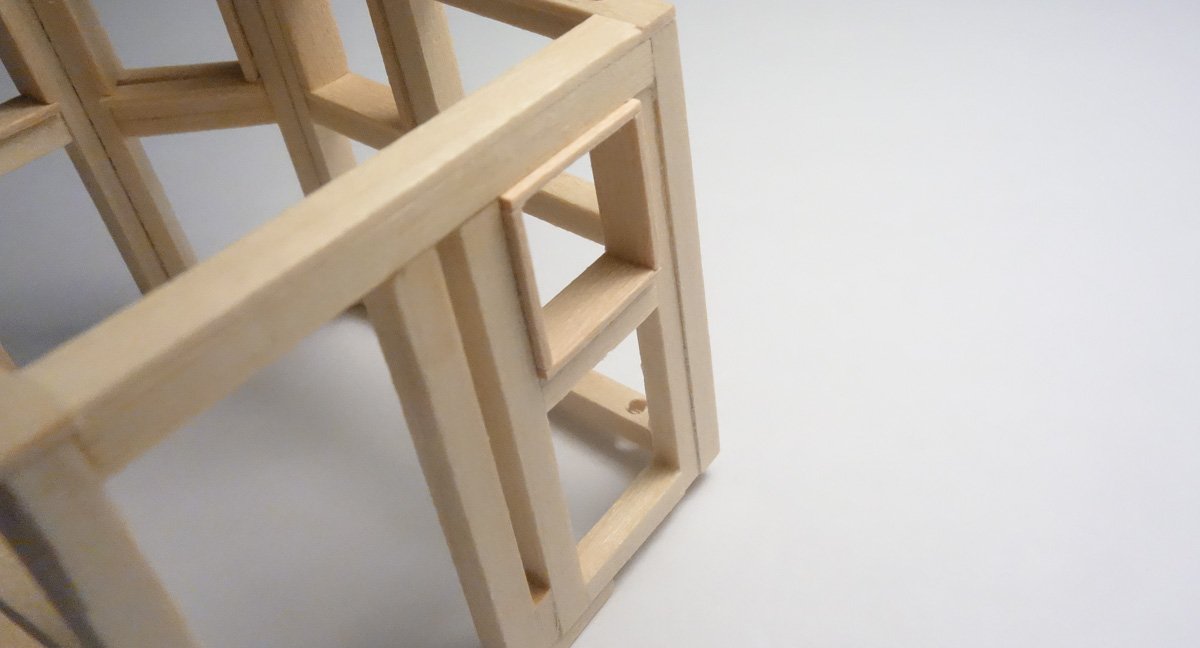
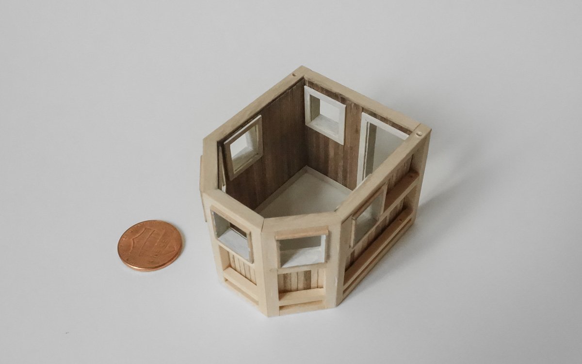
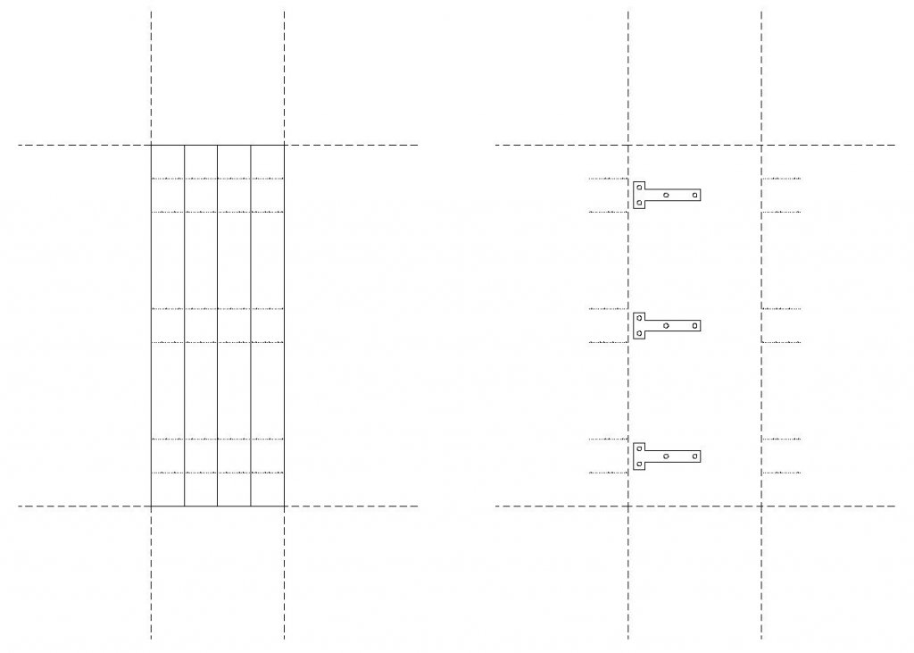
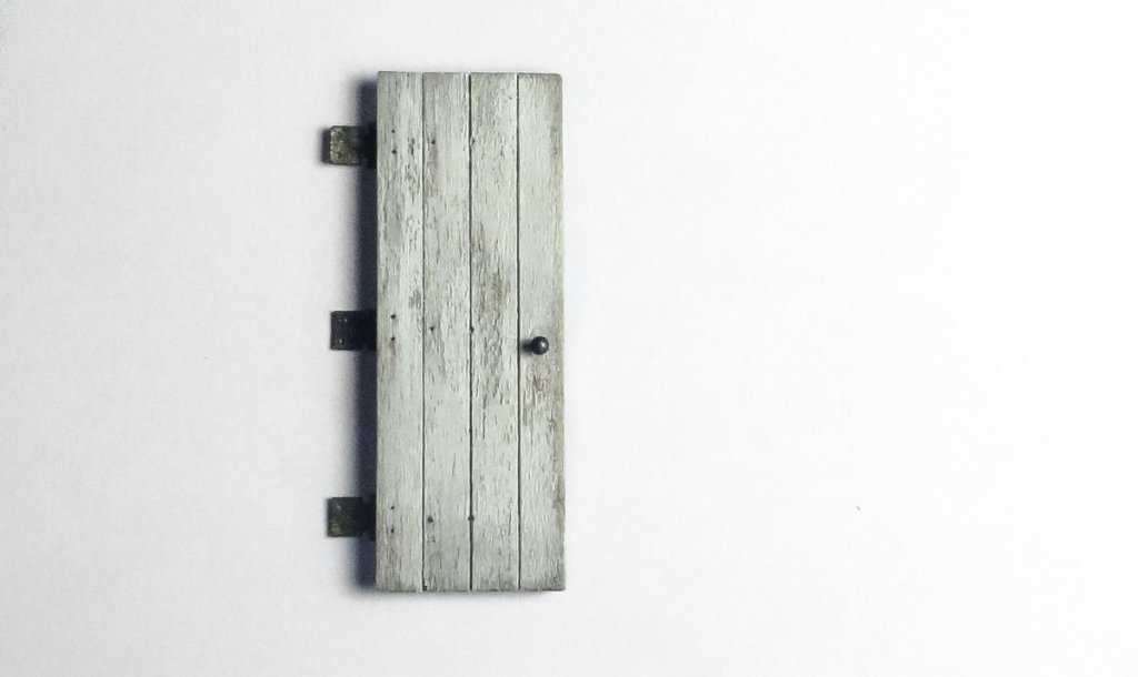
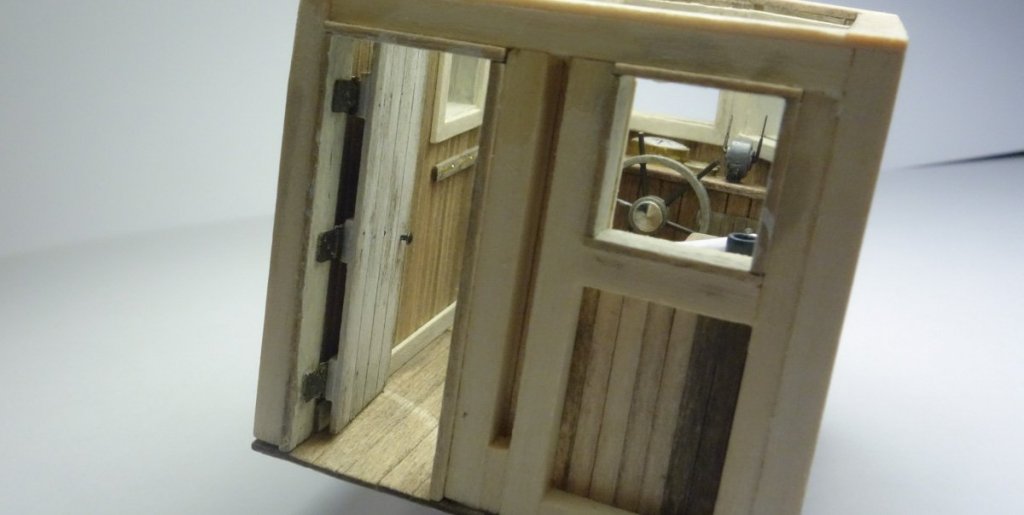
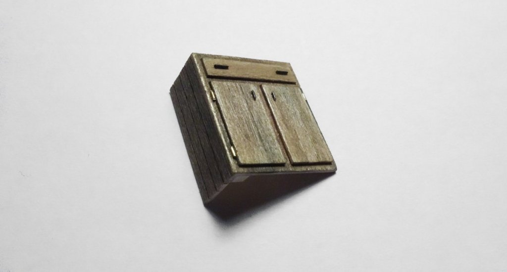
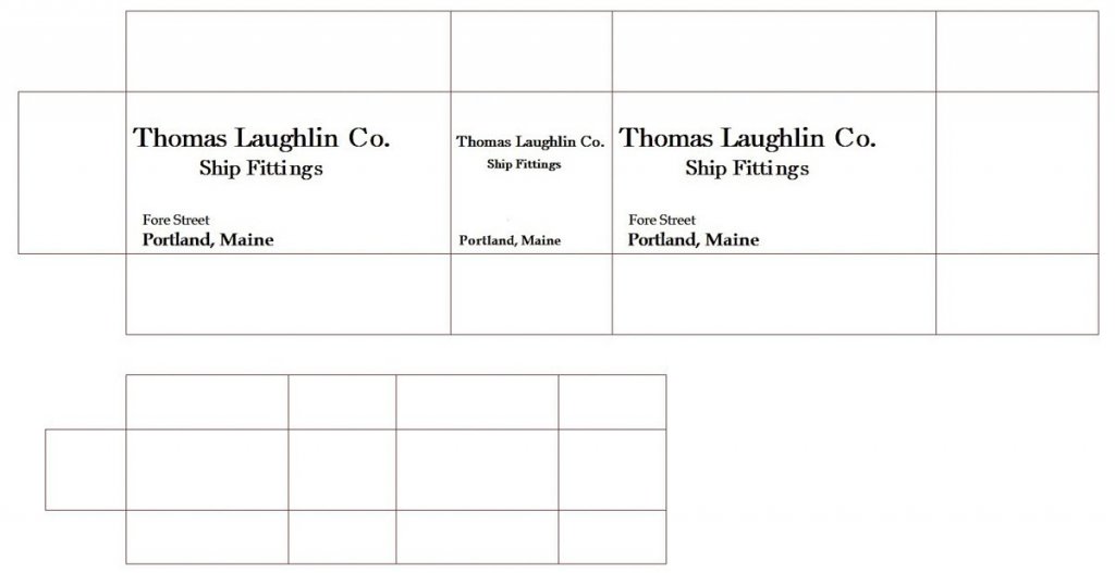
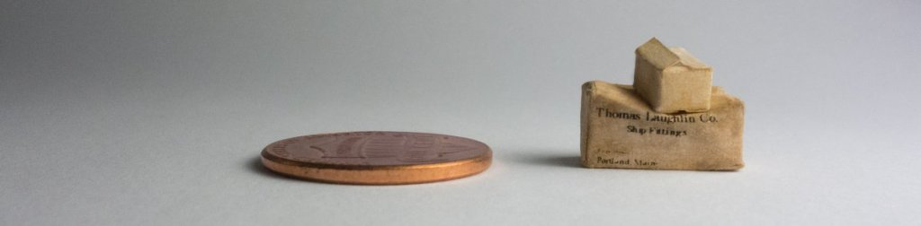
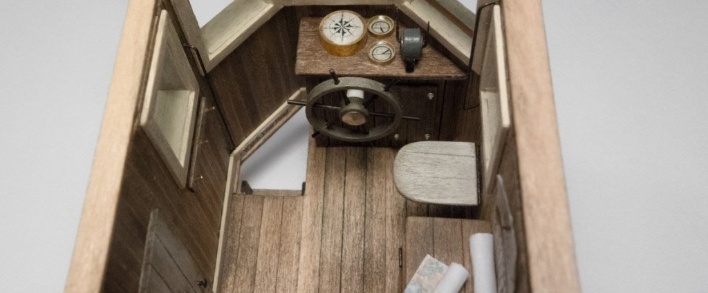
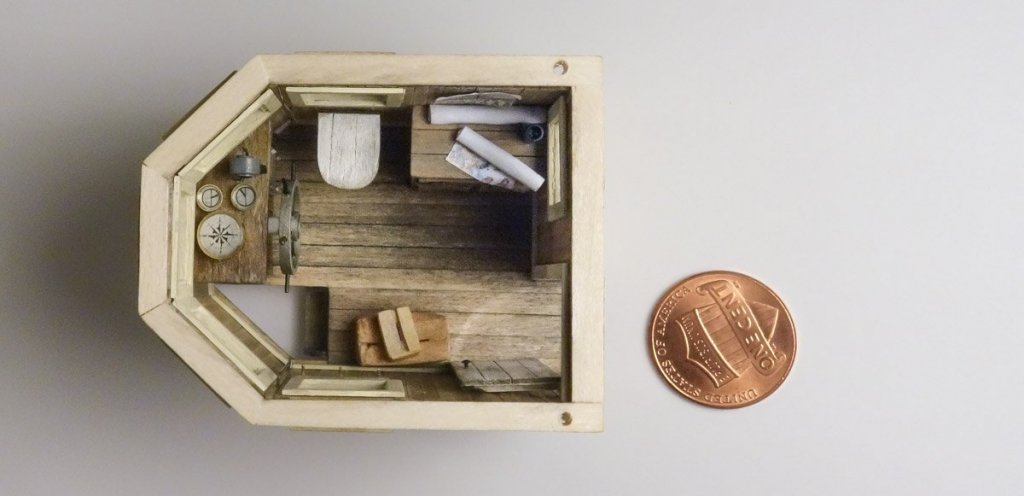
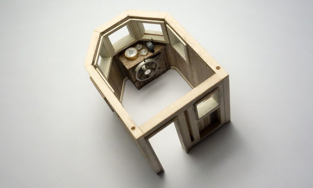
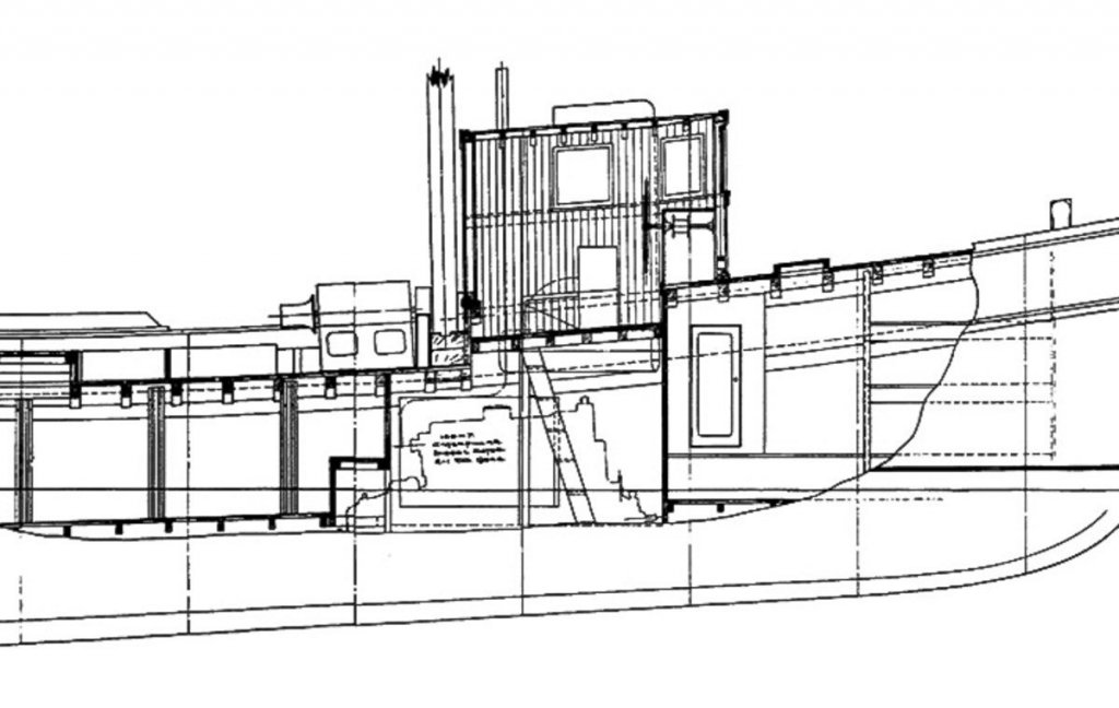
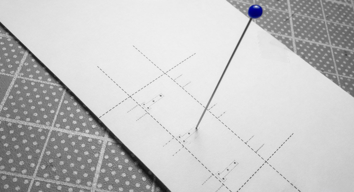
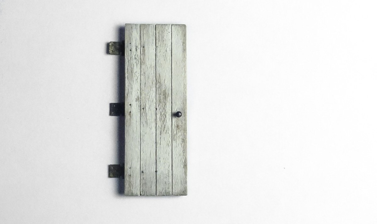
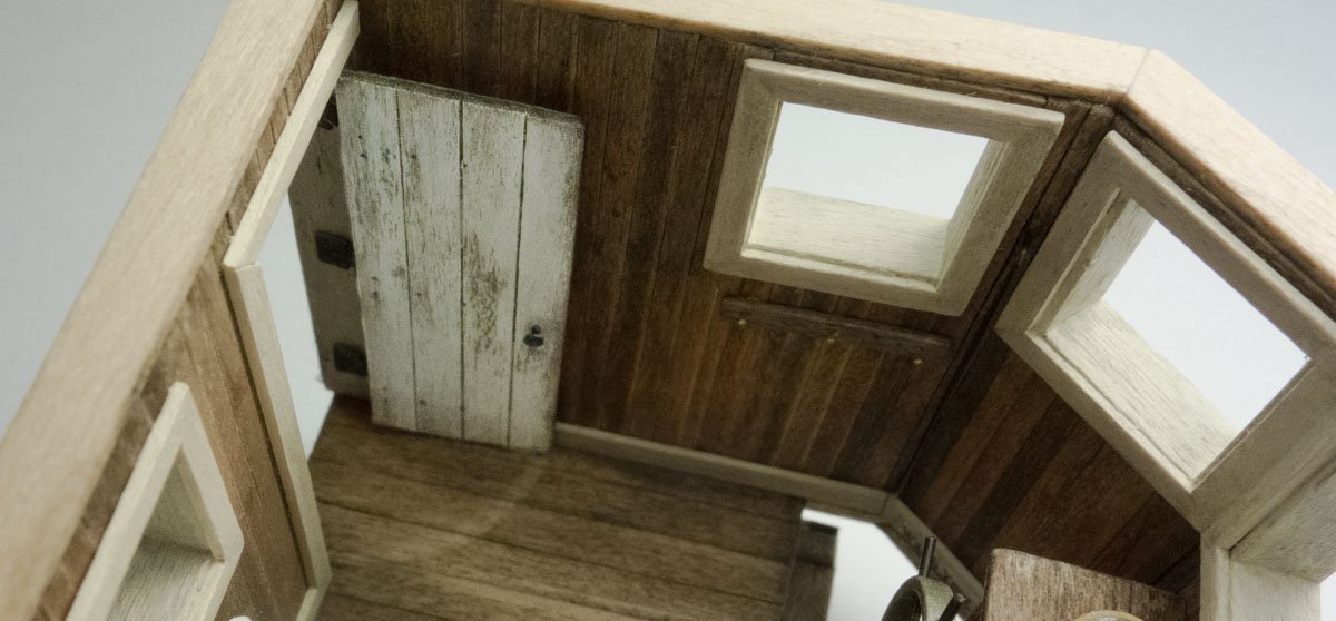
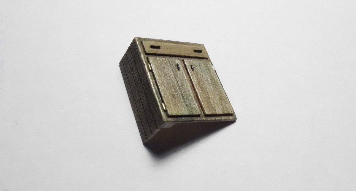
Pilothouse Interior #3 This update will complete the pilothouse interior. There will be a separate switch somewhere on the display base to operate an interior cabin light, so I need to provide some interior details. The question for me is always - how much detail is enough? The level of detail found in the real world is simply way beyond my ability to recreate. So instead, I try to suggest detail and depend on the mind’s eye to fill in the rest. I began with the door, which will be open. I drew it up along with a bolt pattern for the strap hinges that would typically be attached to the rails on the reverse side of the door. The door swings inward and up against the wall so the hinges won't be visible and therefore have zero detail. I first made up some hinges from styrene. They are scale 4” wide. The door itself was made up from four strips of wood glued to three rails. It was then positioned on the backside of the drawing template so I could mark the hinge bolt locations. Once the door was colored, I blackened the pinholes that simulate the hinge carriage bolt heads. This was done by poking a very fine dressmaker’s pin into the tip of permanent marker then placing it into the hole and giving it a little twist. A pinhead is used for the doorknob. The hinges look too large to me. After the exterior siding and door trim are placed, I'll re-evaluate. If they still look too large I’ll try coloring them to contrast less with the jamb. Under the window is a coat rack. I intend to hang a coat or rain slicker there, but simulating material with the correct texture and drape at this scale is a challenge and needs some rethinking. So for now, it remains empty. I made a cabinet with a flat upper drawer for charts and what not. I installed the cabinet and added a top and a few rolled up charts. Also shown here is a fold down seat for the skipper and a vertical grab iron between the windows. This model will be displayed as a vessel under repair. And repair work requires repair parts, which often come in corrugated boxes. So I’m going to place a couple of them under the coat rack. I’ve played around with different ways to model small boxes before and always come back to the most simple - folded paper. So I start with a drawing of an unfolded box complete with printing. The most difficult part of this process is getting the color right. Using gauche in a very watery mix of yellow ochre, burnt sienna and grey produced an acceptable result. Any color medium that doesn’t bleed the lettering will work. I then cut the "boxes" from the paper and folded them up. But simply folding and stacking them produced disappointing results. They looked like what they were - little pieces of folded paper pretending to be boxes. They need to look like they have weight. So I modeled the larger box to look as though it had been wet at one point and the smaller box was thrown on top. The cut out in the floor provides access to the engine room, galley and berths. There is a ladder/stair that descends down, but only the top tread is visible from any cabin opening - so that is where the modeling stops. That completes the interior and I’m glad to be getting out of such cramped quarters. Thanks for taking a look. Gary


.thumb.jpg.aabd5b10032072ce407bd98ad81177e7.jpg)

- 424 replies
-
- 31
-

-
Thanks John, I appreciate the comment. Add to that - charming, witty and irresistibly to women and you have a good start on a list of attributes I have never possessed. But I appreciate you giving me the benefit of the doubt. Thanks for the positive comments Patrick. I’m glad you stopped by. Hi Josh Thanks for the kind words and for stopping in to take a look. I’m happy you have found something of interest here. Hello Keith and Vaddoc. Thanks for the vote of confidence on a weathering techniques log. I think it might be a fun exercise. But it will be a while before this boat is done and I’m a “one at a time" sort of modeler. Thanks for your support. Hi Keith. Wow – that’s kind of rough on the Gelcoat isn’t it? I appreciate all technological advancements in the many aspects of our lives, but I think we've become obsessed with it and have grown too dependent on it. Mostly, I try to live and enjoy life simply. Thank you for your comments Keith.
-
Hello Druxey. It’s kind of an obscure product that I stumbled across a few years ago. I read about a modeler that was using it to add lenses to his portholes. He would load the side of a toothpick with the liquid and screed it across the round opening. The material has enough surface tension to bridge the gap. Thank you for your comments and for stopping by. Thank you so much Vaddoc and thanks for taking an interest in my log. Gary
-
What a difficult decision to make, but it would have troubled you every time you looked at the rigging. I take my hat off to you for correcting what few people would have noticed. This is just one of the many reasons why your model is so wonderful and you as a modeler are so excellent. Well done Alexander. Gary
- 306 replies
-
- 5
-
-
- schooner
- la jacinthe
- (and 1 more)
-
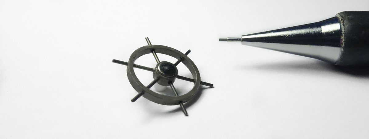
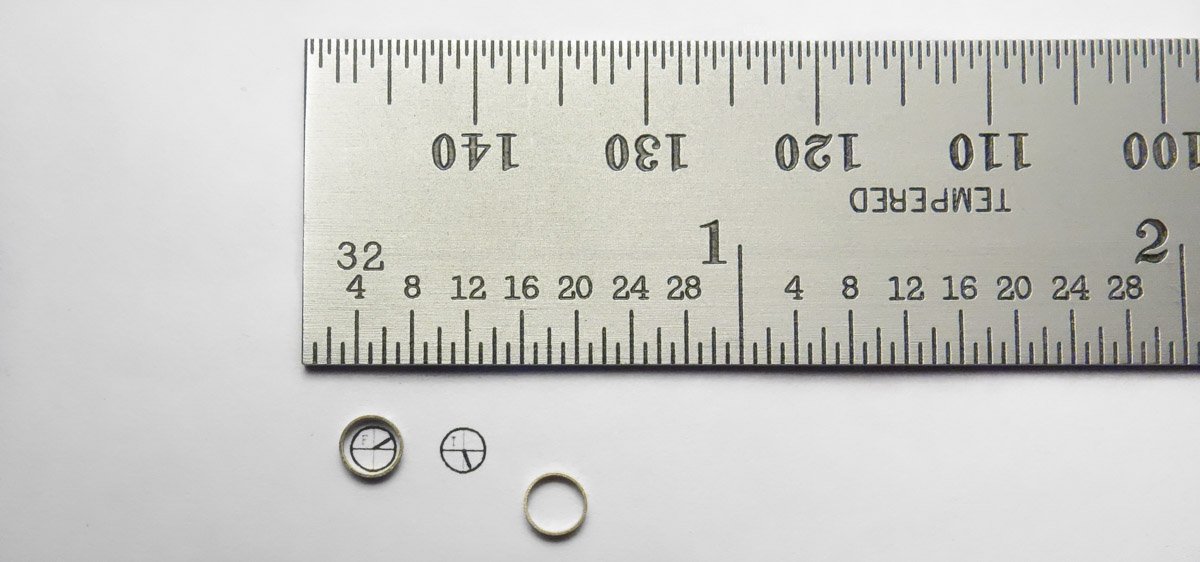
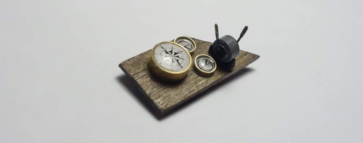
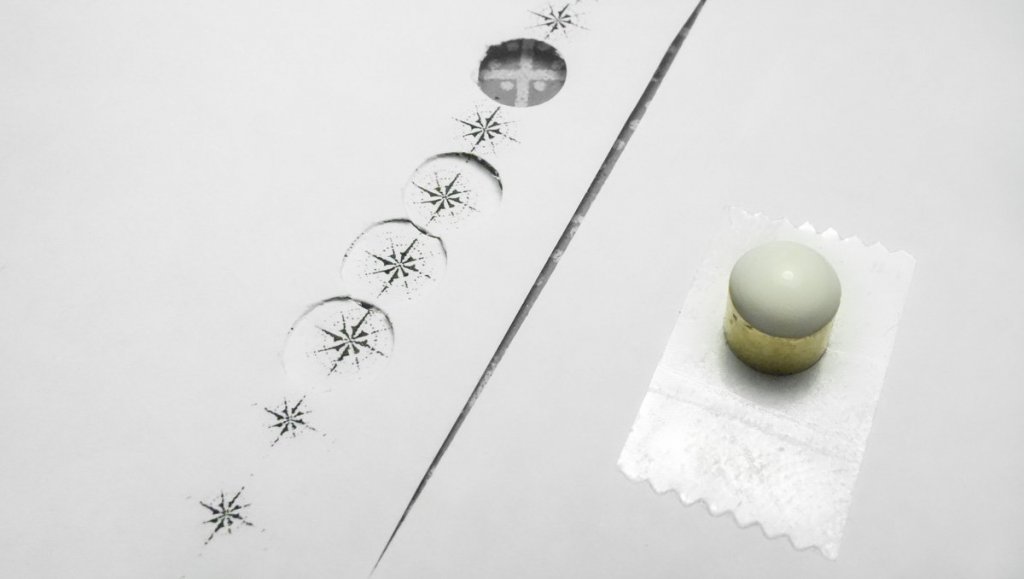
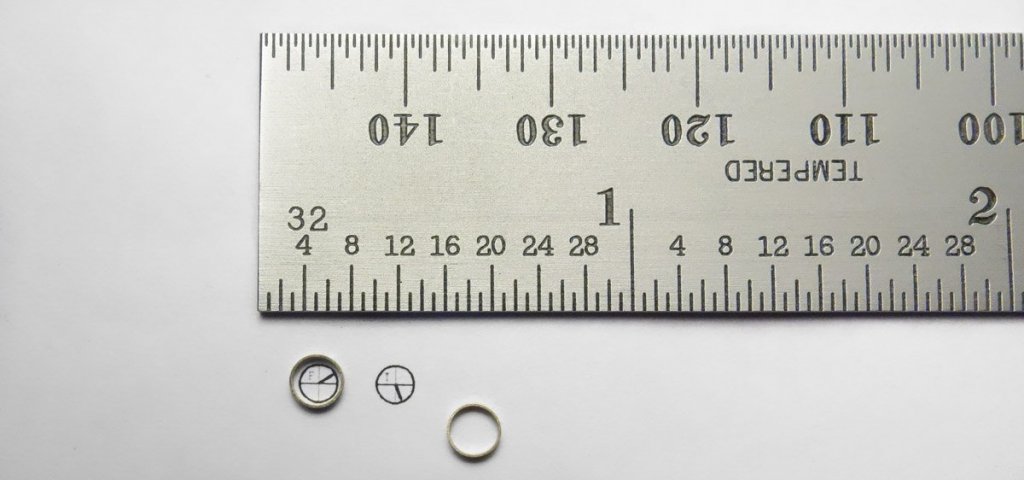
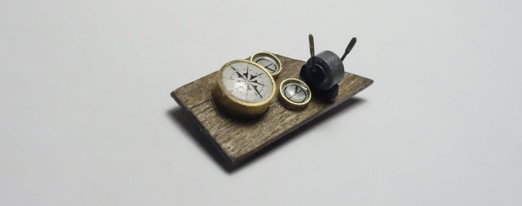
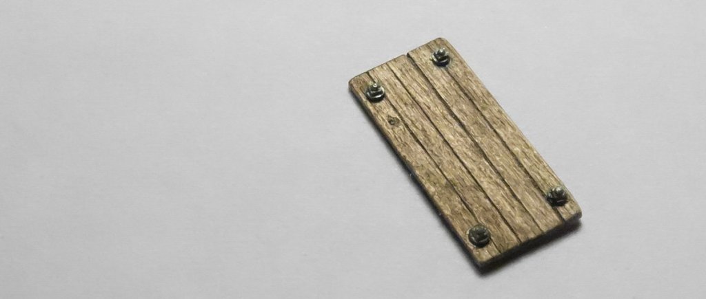
Keith Black and Alexander - Thank you so much for kind comments - I appreciate it. Thanks for the supportive comments Keith. Perhaps I may post a compilation of techniques in the forum "Tips & Tricks" once this build is complete, but I'm not sure how much overall interest there would be in it. Thanks, I'm pleased you're enjoying the log and happy to have you looking in. And thanks to everyone stopping by and hitting the like button. Pilothouse Interior #2 The navigation and control area on this boat is compact and simple. Besides the ship’s wheel, there is a compass, throttle/clutch control and a couple of instrument gauges. I begin with the wheel which is 36” in diameter including handles. Photos of these boats show both traditional wooden wheels and simpler steel wheels. I chose to go with steel because in all honesty, it is much easier to make. It is put together from styrene and brass wire. The styrene is painted with enamel and the brass is blackened. The compass is made from ¼” O.D. brass tube. A styrene plug was inserted to hold a printed image of a compass rose at a point just below the rim of the compass. A couple of drops of Gallery Glass are placed on the surface which when dry will provide a clear “lens” for the compass. If you’re unfamiliar with Gallery Glass, it is a craft store available product that has a number of modeling uses. It comes in different colors and dries clear like stained glass. It doesn’t dry hard like epoxy, but more like hard rubber. The colors can be mixed and typically leave no air bubbles - but it does shrink and more than one application is often required. It is non-conductive so you can encapsulate LEDs to insulate the solder joints and produce the color output you want at the same time. If you repeatedly dip the end of a fiber-optic into white or clear and each time letting it dry in the vertical, you end up with a scale light bulb. The two gauges are produced in a similar way by placing a thin slice of 1/8” brass tubing over an image and adding a drop of Gallery Glass to the center. The Gallery Glass adheres to the paper and brass and all that needs to be done is cut the paper away from around it. A throttle/clutch control is made up from styrene and brass. The gauges, compass and throttle are attached to a console top. A console bottom is made... … along with a bolt-on access panel. The nut/washers are styrene. Everything is combined and glued into the pilothouse. Thanks for stopping by. Gary


- 424 replies
-
- 29
-
-
Great job on all those mast fittings G.L. And thanks for that overview post - it was a big help. I’m looking forward to future posts and progress on your row boat. Gary
- 219 replies
-
- 2
-
-
- smack
- cross-section
- (and 2 more)
-
Wonderful craftsmanship as always Alexander. Beautiful. Gary
- 306 replies
-
- 3
-
-
- schooner
- la jacinthe
- (and 1 more)
-
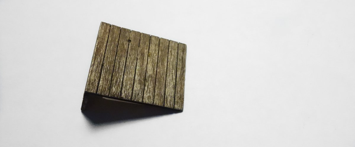
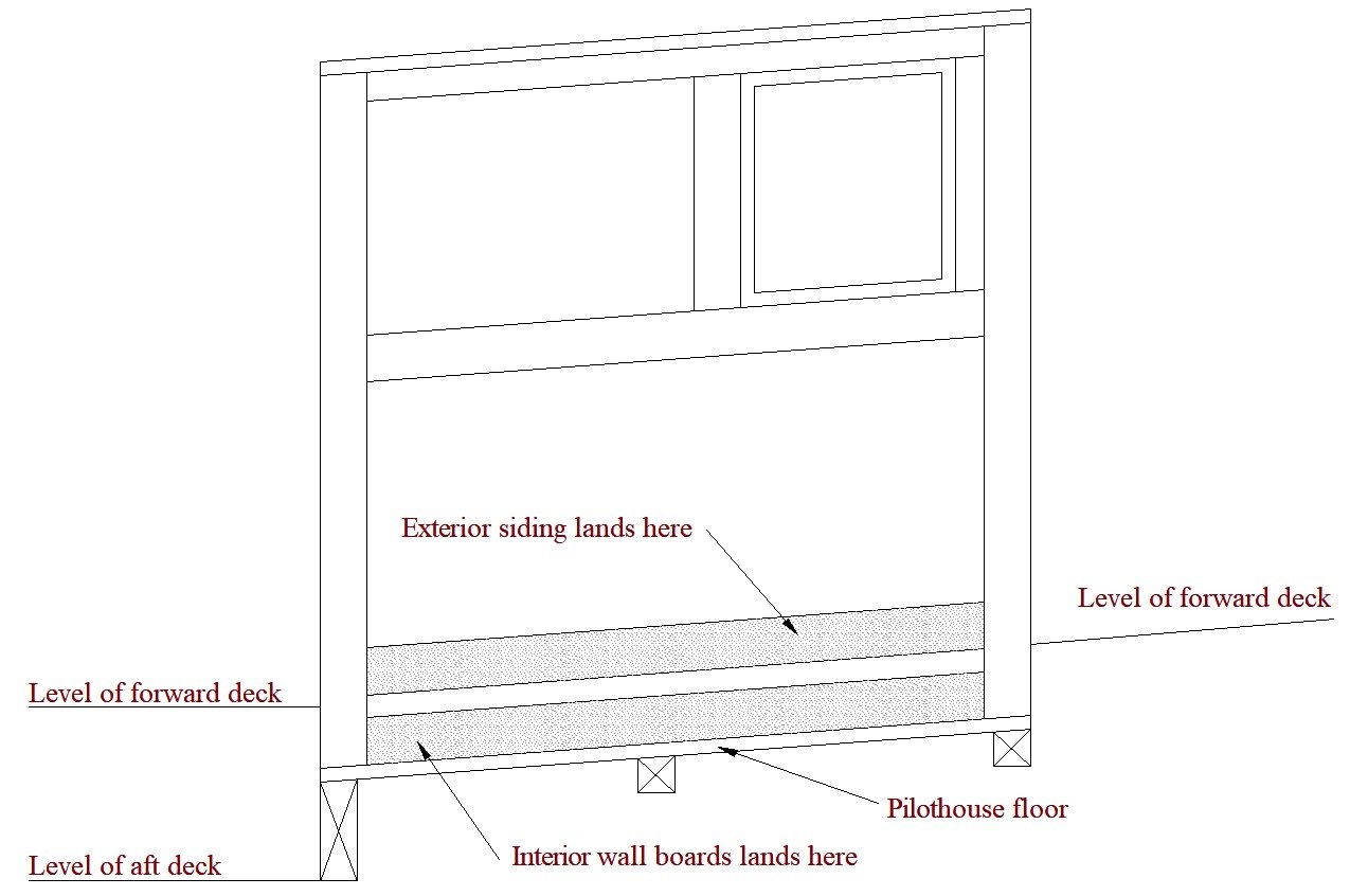
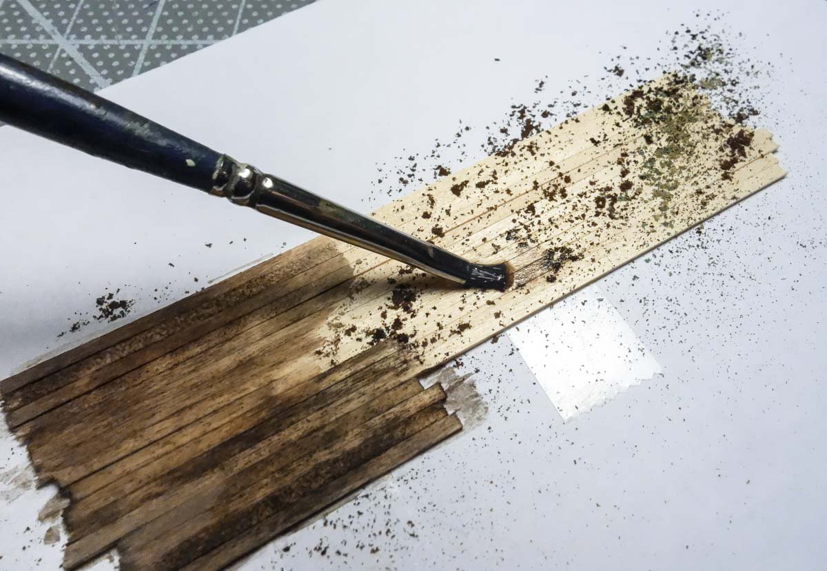
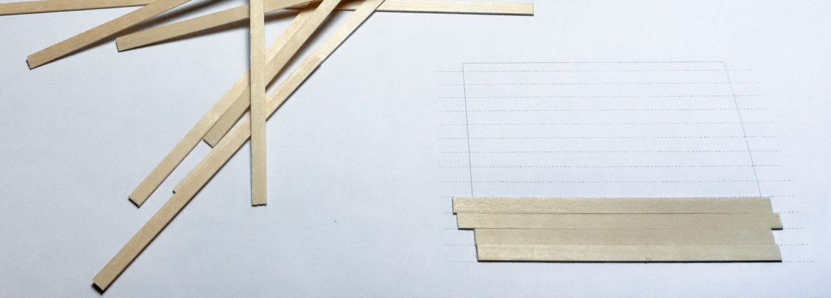
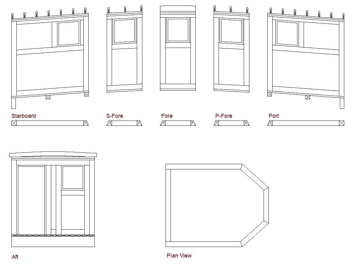
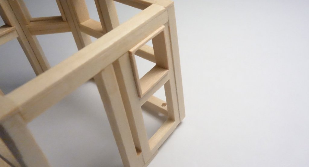
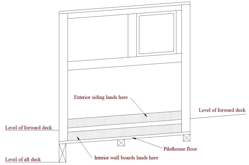
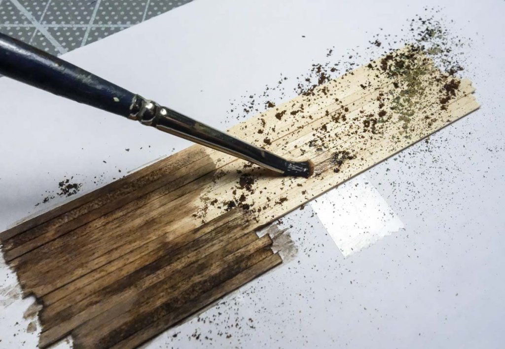
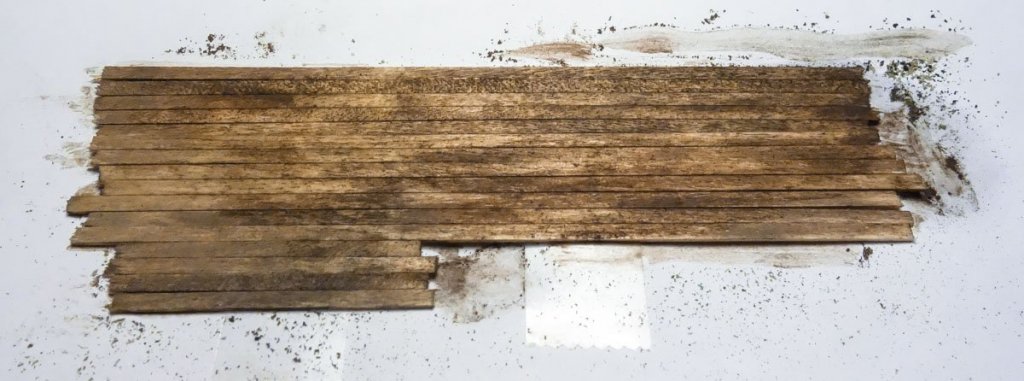
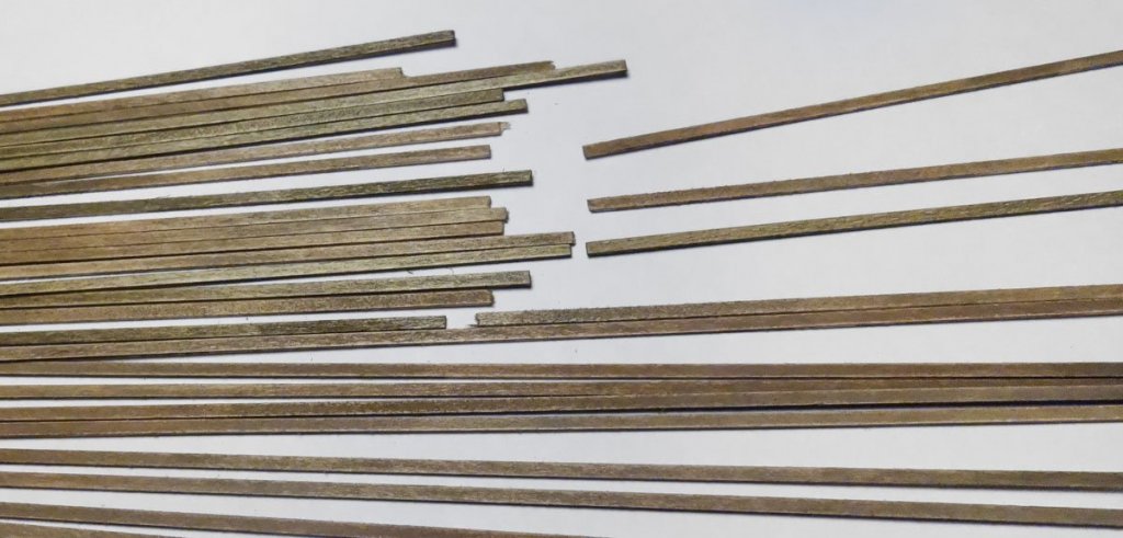
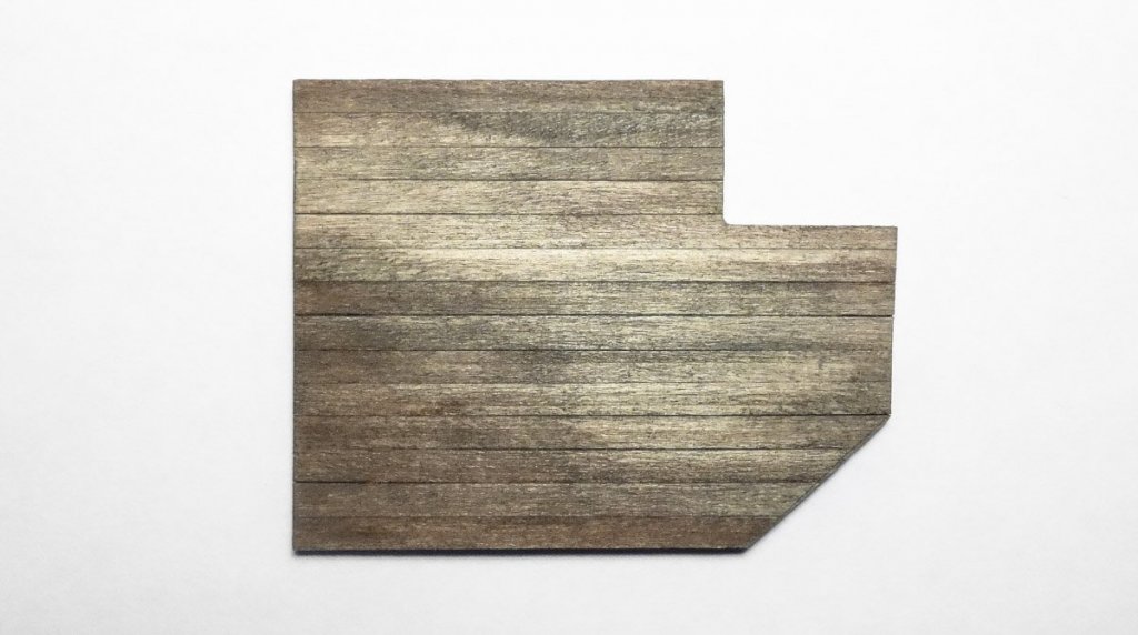
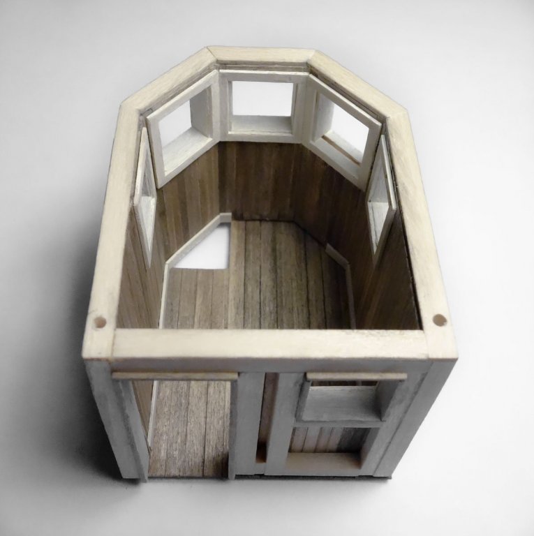
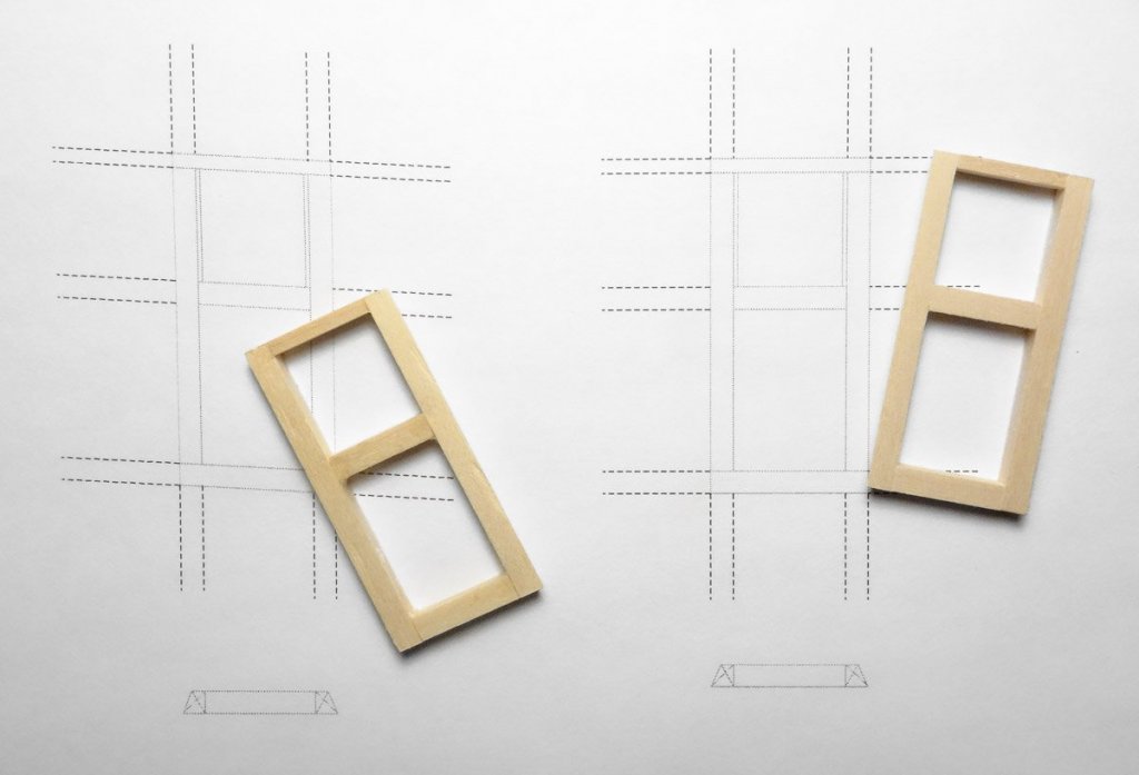
Thank you John and Keith. And thanks to everyone looking in and hitting the like button. Pilothouse Interior #1 With the frame for the pilothouse done, it’s time for the interior wall covering. But first I need to install the jambs on the six windows and the door. The jambs protrude from the frame both inside and out because they need to be flush with the outer surface of the wall covering. They are cut from 1/32” basswood sheet. This material is out of scale, but once the trim casings go on, only the face of the jambs will show with a reveal on the edges. The openings of the frame were cleaned in the corners before the jambs went in to remove any adhesive squeeze out. Next I added a band of wall frame cross supports that will serve as a landing spot for the lower edge of the exterior siding. This is necessary because the pilothouse floor is lower than the forward deck as shown below. The interior vertical wall boards are about 3.5” wide. I begin by staining a trial batch of wood. I stick the wood down to a sheet of paper using double-sided tape. Chalk is scraped off the side of sticks directly onto the wood and alcohol is used to liquefy and spread it. I want color variation so several chalks are unevenly applied in loosely defined mini piles. If the colors are evenly distributed it simply blends into a homogeneous color and that is not what I’m after here. The color is darker when wet and certain colors will not fully emerge until it has completely dried. I didn’t care for the reddish oxide tone of the trial batch, so I changed colors and found something closer to what I had in mind. In the end a scattered mix of burnt umber, raw umber and burnt sienna was used. The raw umber has a subtle green tint that I like. When it was dry, I went over the surface with fine sandpaper. To bring up a slight sheen, I lightly polished the wood with a little beeswax on the tip of my finger – more like burnishing really. Then the floor of the cabin was constructed by gluing 6” wide floorboards directly to the template and cutting away the waste. It was stained and a foot traffic pattern worn in. The floor is reinforced on the bottom side. Next I made up the interior window casings. I first drew up the six window cutting templates. Only the fore and aft facing windows have square corners. Then with the aid of double-sided tape, I cut and glued the casings together. I painted the casings, window jambs and material for the shoe base an off-white acrylic. I then glued the vertical wall boards and all the trim into place. Sitting on the floor section. The floor will not be glued on just yet. Thanks for stopping by. Gary


- 424 replies
-
- 27
-
-
Hello Keith Nice technique using the spent utility knife blade to profile the rub rail. I will remember that. I can see this being useful in many applications. Thanks. Gary
-
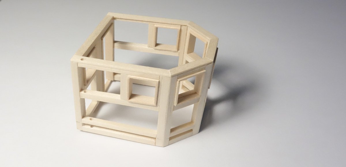
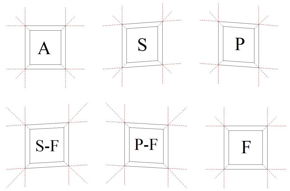
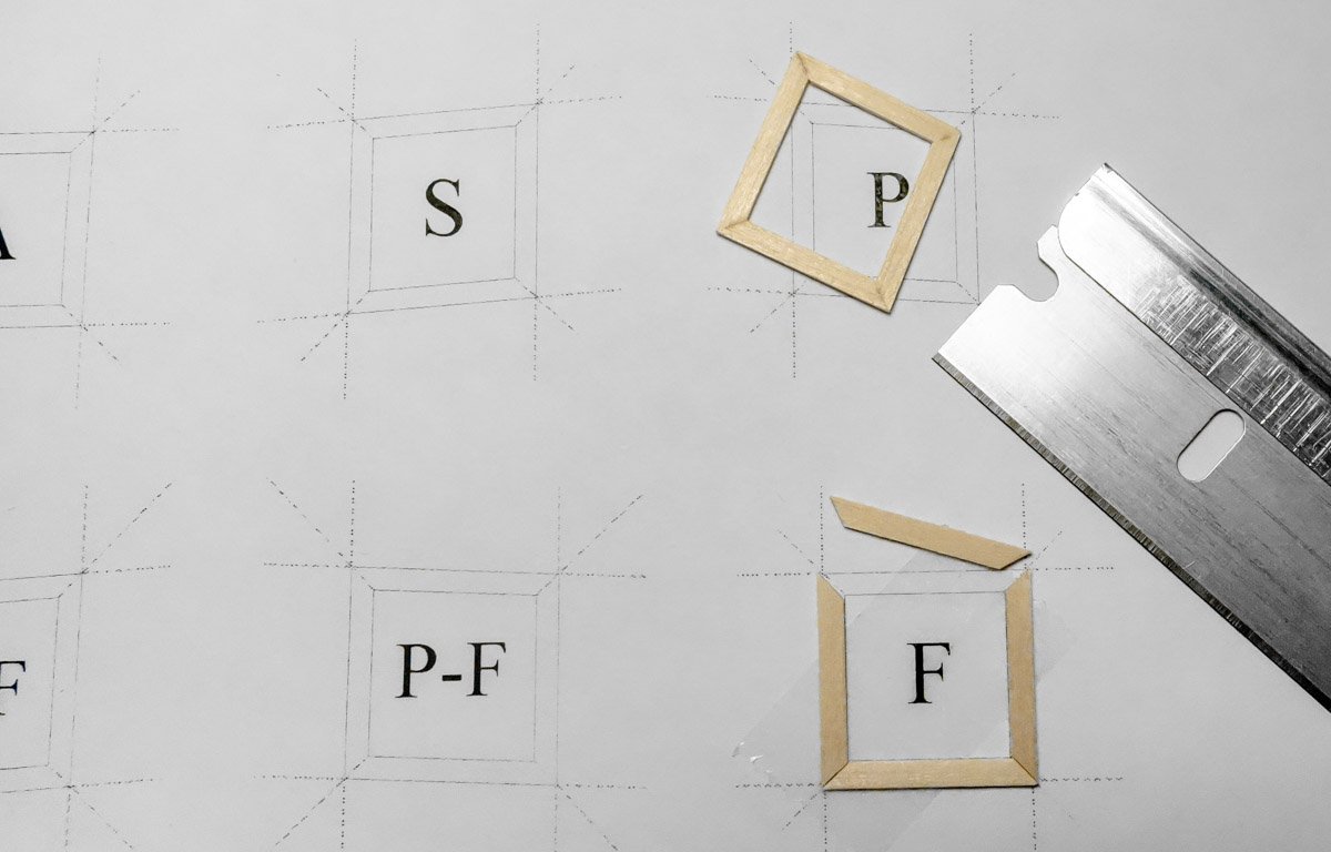
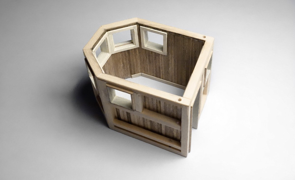
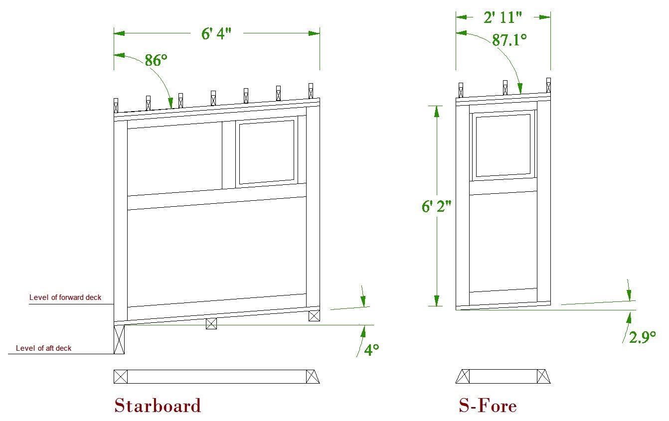
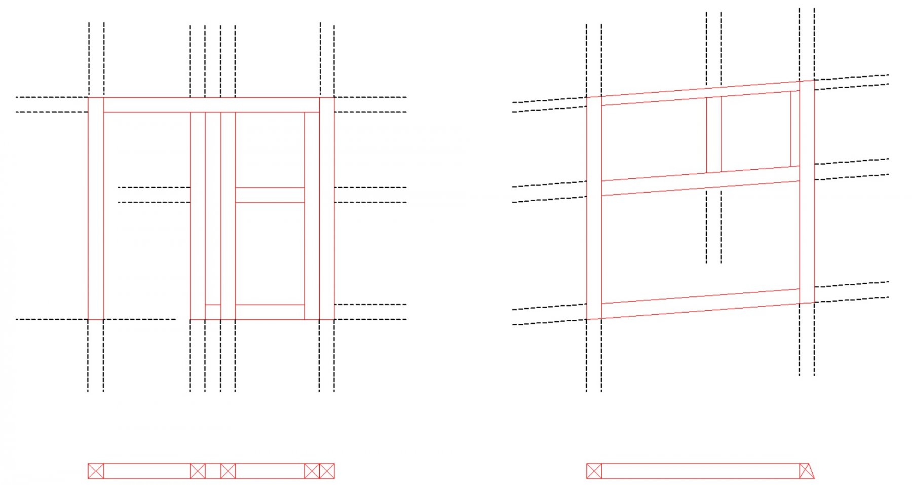
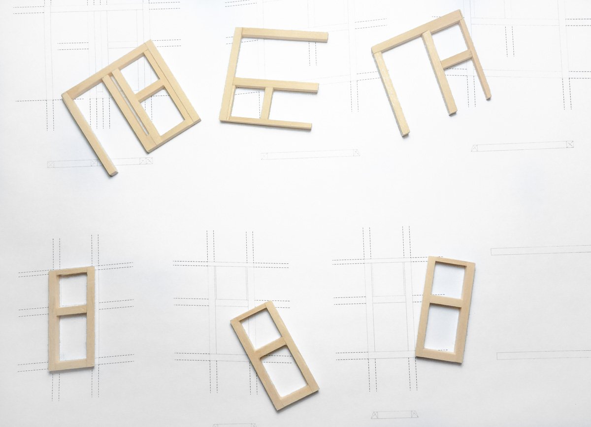
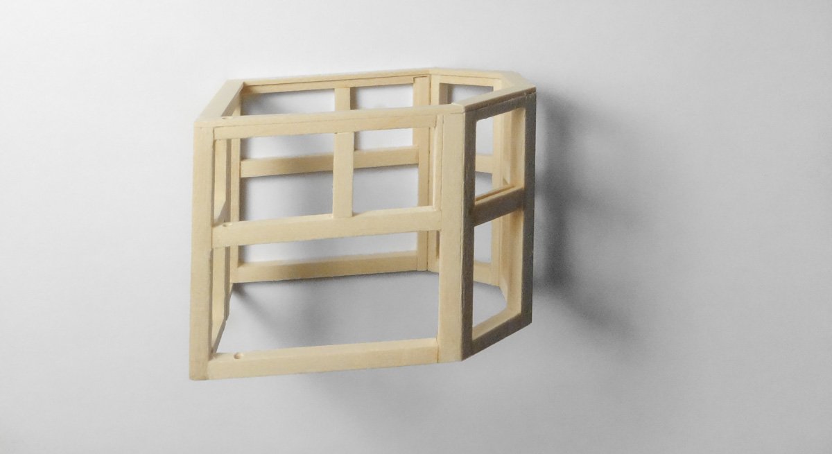
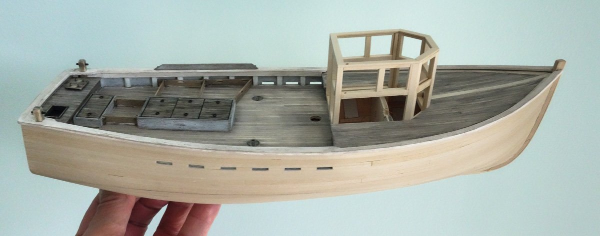
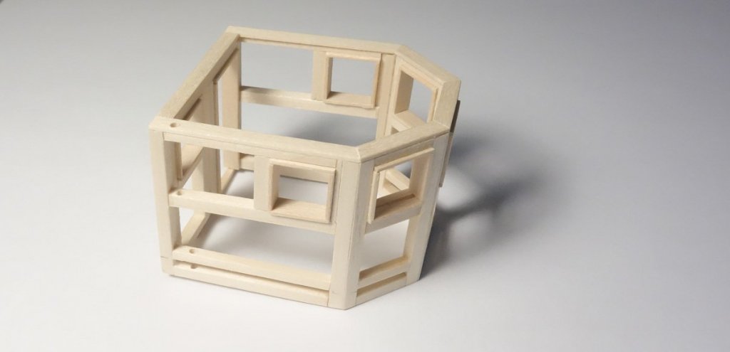
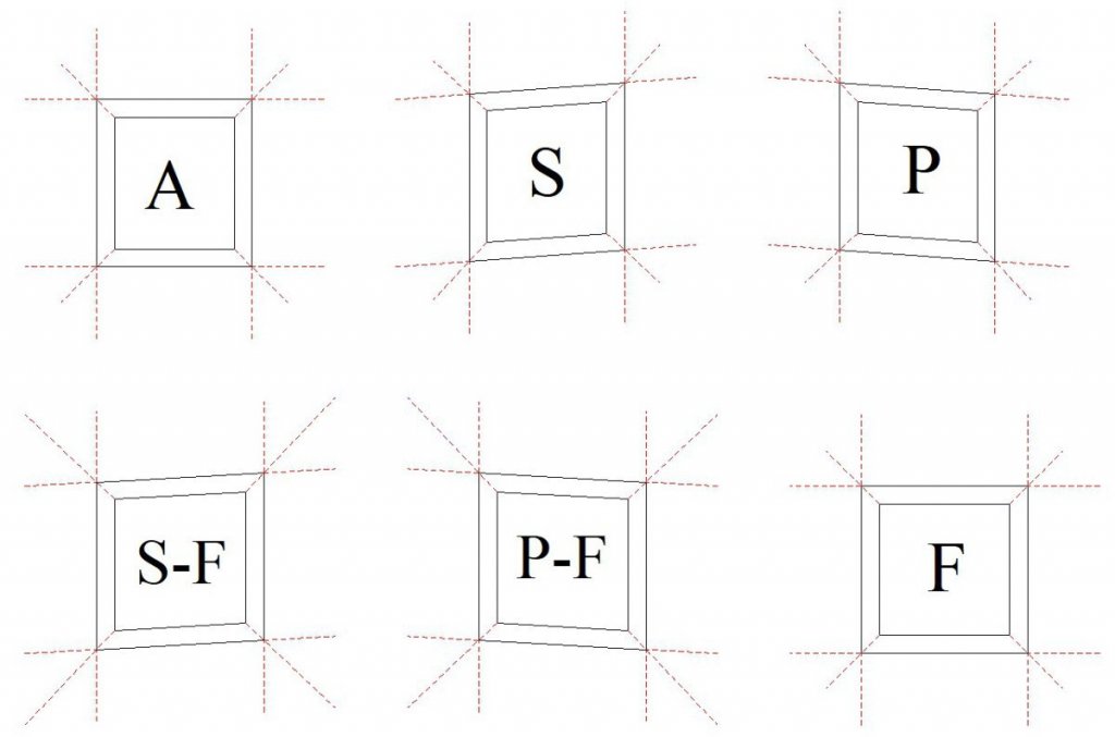
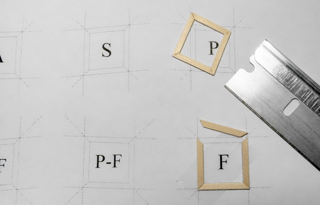
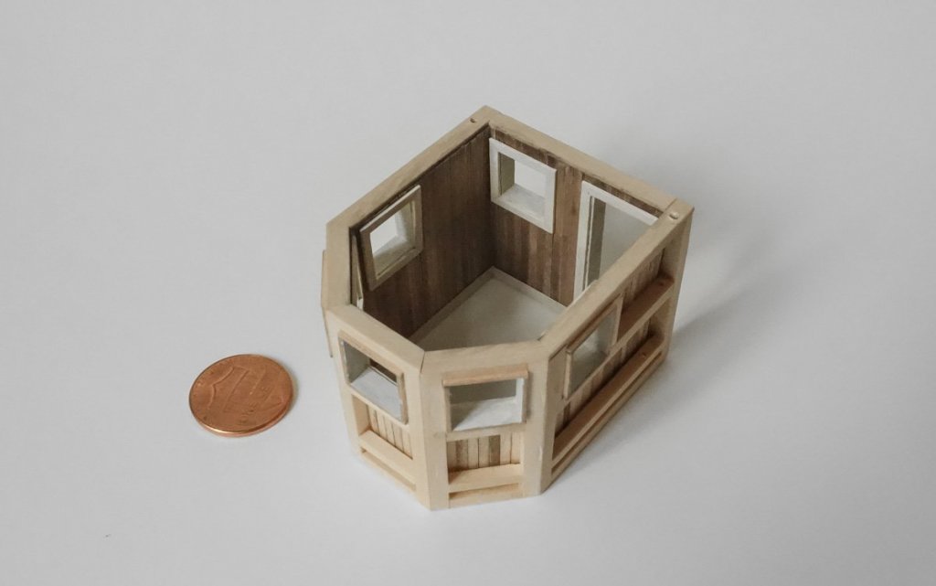
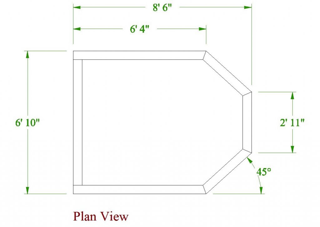
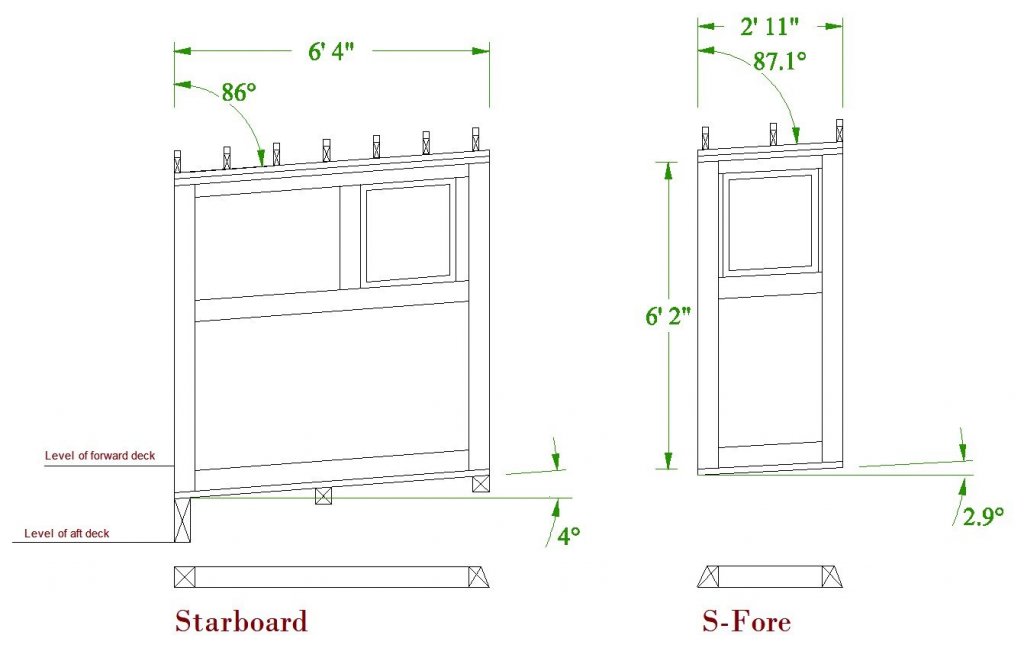
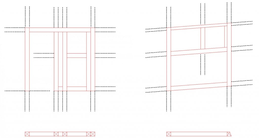
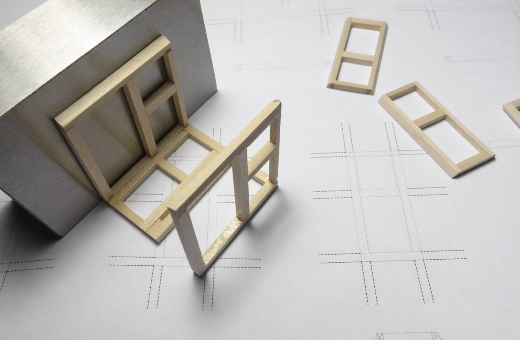
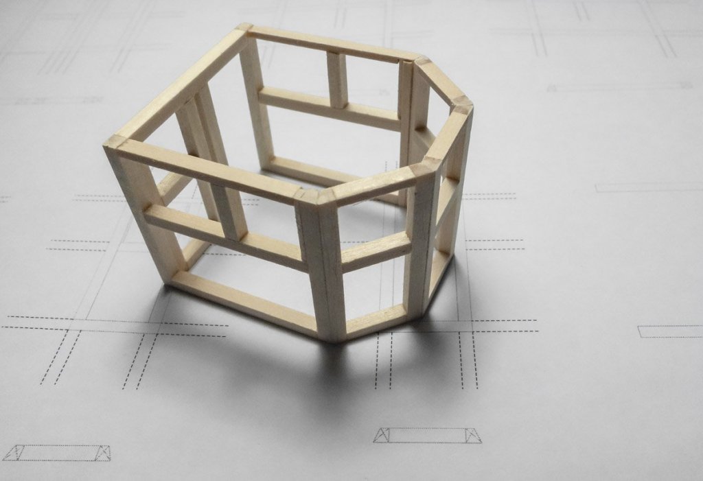
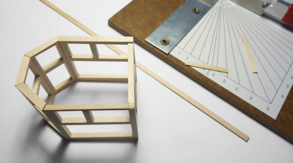
Dave and Alexander - Thank you very much - I truly appreciate it. And thanks to everyone hitting the like button. Pilothouse Frame Here’s a profile drawing of a typical pilothouse for this boat. I used the above image and a similar one of another boat to produce the pilothouse drawings for this model. The mast on this boat is perpendicular to the water line and the aft facing wall of the pilothouse is parallel to the mast. The roof and floor have a 4-degree pitch upward as it extends forward, so the sidewall framing forms a parallelogram rather than a rectangle. The small front angled walls are less steeply pitched because they point away from the sidewalls at 45 degrees. They have a pitch rise of only 2.9 degrees. All six walls are drawn up. Cutting templates and part locating drawings are printed for all walls. Basswood is cut and assembled into wall sections. Then the wall sections are combined. Strip wood is cut and mitered for use as wall top plates. They extend a tad into the interior beyond the wall frame. This serves as a termination point for the vertical interior wall boards when they are placed and it also provides a wider landing spot for the roof beams. Holes are drilled through the framing to hide the wiring for the P/S running lights, interior lighting and a pair of exterior rear facing floodlights. Notice in the photo below that the middle cross support in the angled wall has been replaced with two parallel facing boards. The windows slide down into pockets and this one window will be shown partially open. When the forward deck was installed, the opening for the pilothouse was purposely left too small. With the frame completed, I now filed the opening to fit. Then the frame was placed just to see how it looked so far. The pilothouse will be detailed and totally completed before it is glued into place. Thanks for taking a look. Gary


- 424 replies
-
- 21
-
-
Absolutely fantastic work on your bird carvings Frank. You have not only carved an exact likeness of these birds, you have captured the spirit of them. I can almost feel the tension in the Green Heron preparing to strike. Wonderful. Gary
-
I know your post above is about the install of the scupper doors, but I couldn't stop looking at the hull. The light reflecting off it really accentuate its graceful form. And all those coats of finish gave it a strong visual depth. Very beautiful Keith. Gary
-
A very fine looking and interesting boat Nils. I look forward to following your progress and wish you the best of luck on your new project. Gary
-
You must be a perfectionist Alexander, because your work is indeed perfect. Your re-working of the stove displays your pride of craftsmanship. All these details - tiller, stove, pumps and carronades are all very finely made. Nice. Gary
- 306 replies
-
- 3
-
-
- schooner
- la jacinthe
- (and 1 more)
-
I just wanted to thank everyone for all the positive and supportive comments on my small diorama. You folks are very kind and I’m pleased you found it of interest. And as always, thanks to everyone hitting the like button. Work on the fishing dragger is moving forward, but the pace has slowed due to - you know - yard work. Gary
-
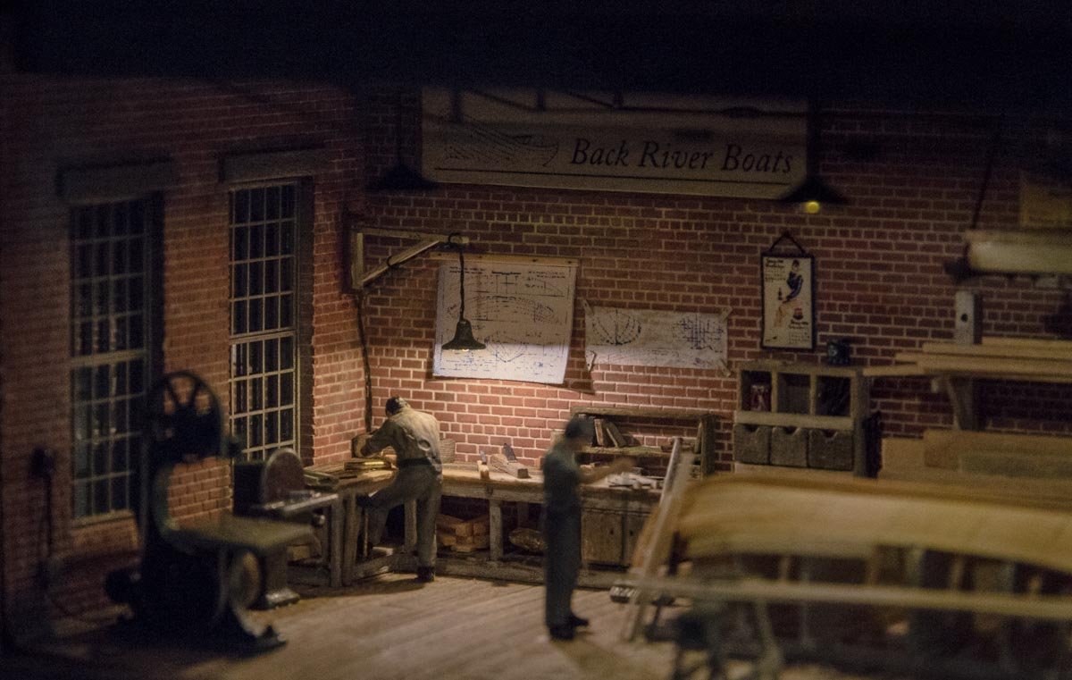
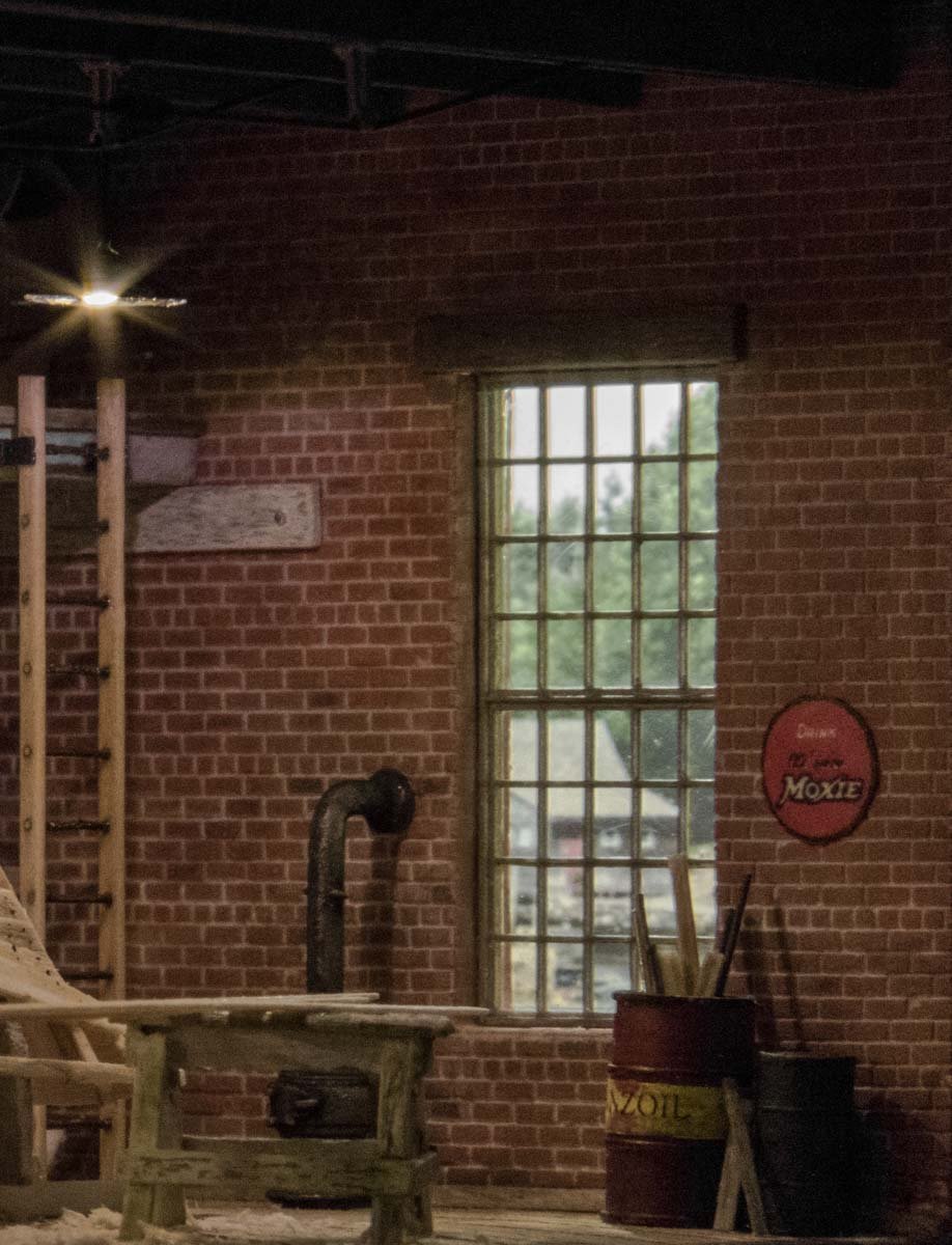
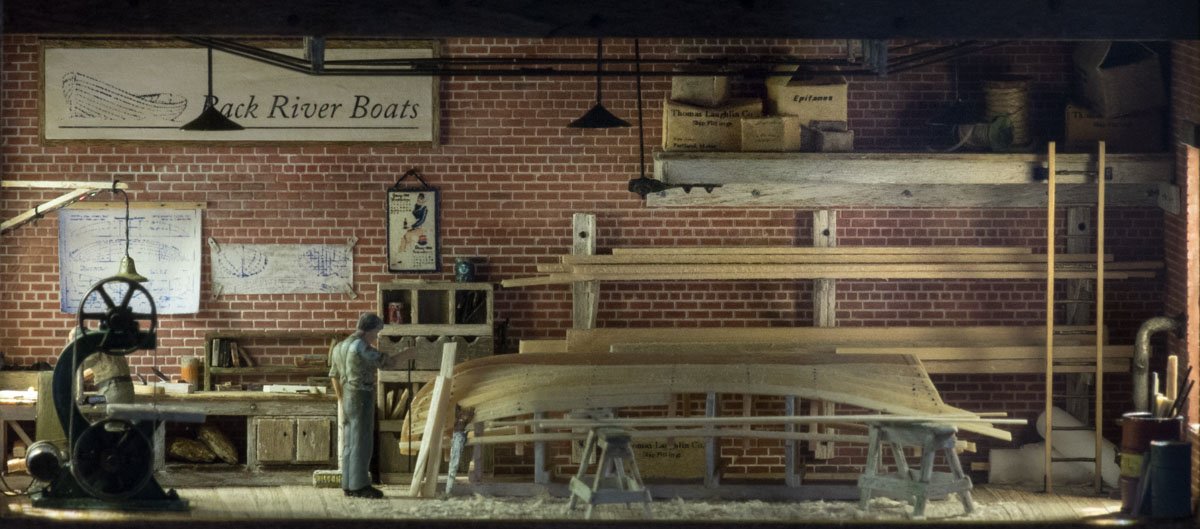
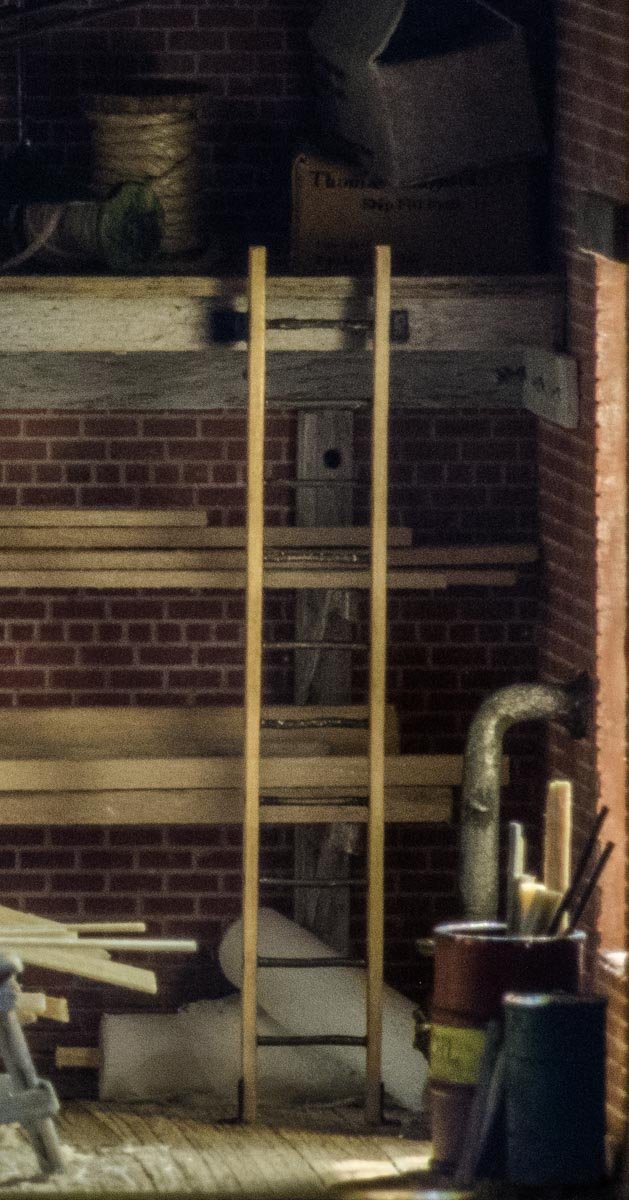
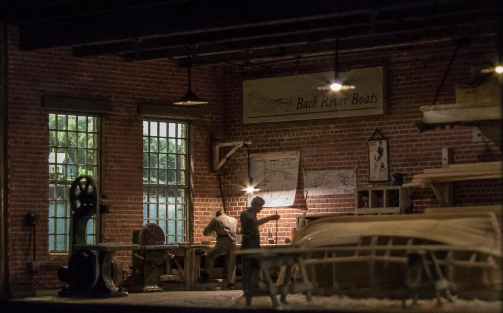
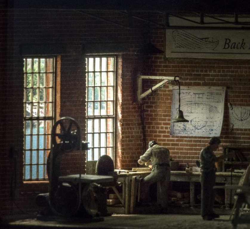
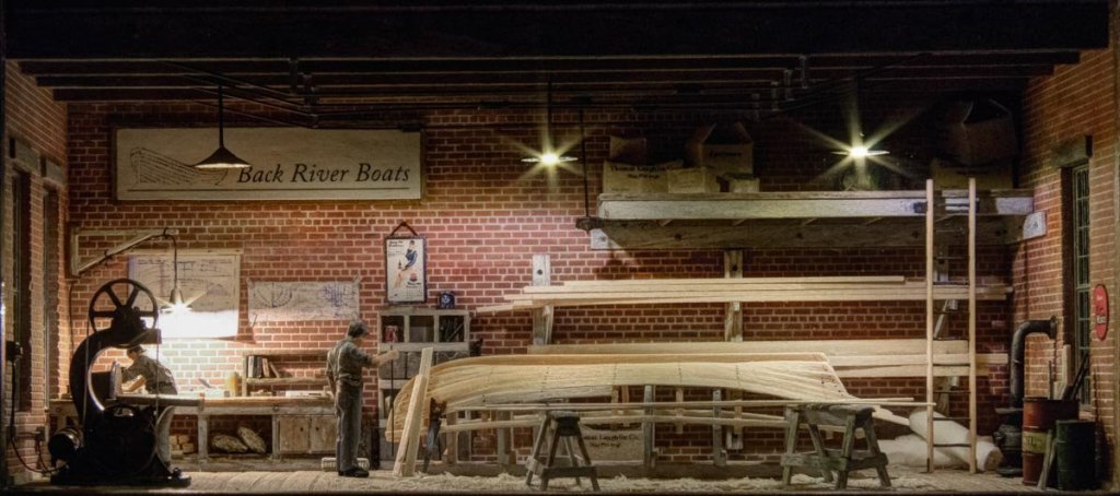
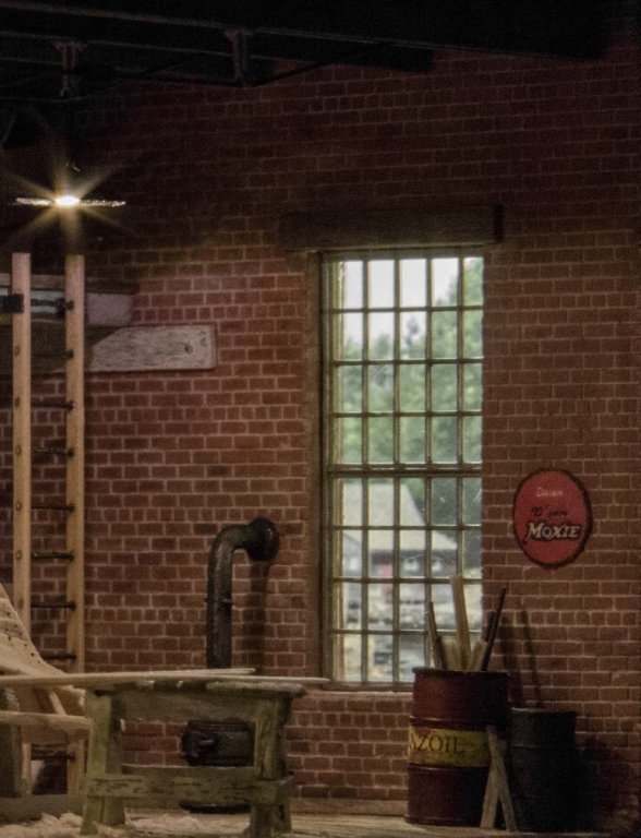
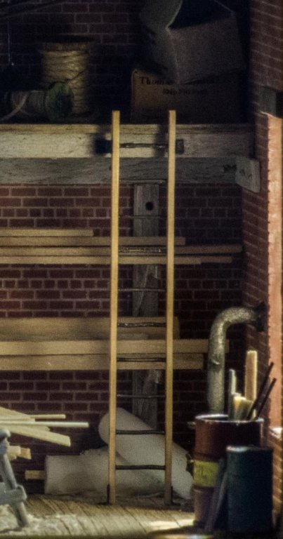
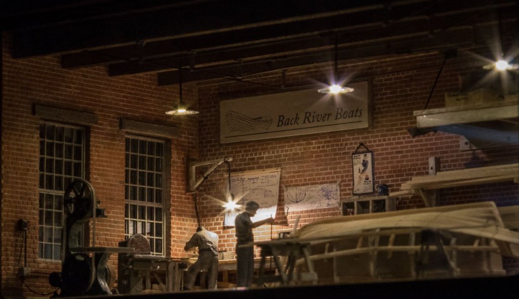
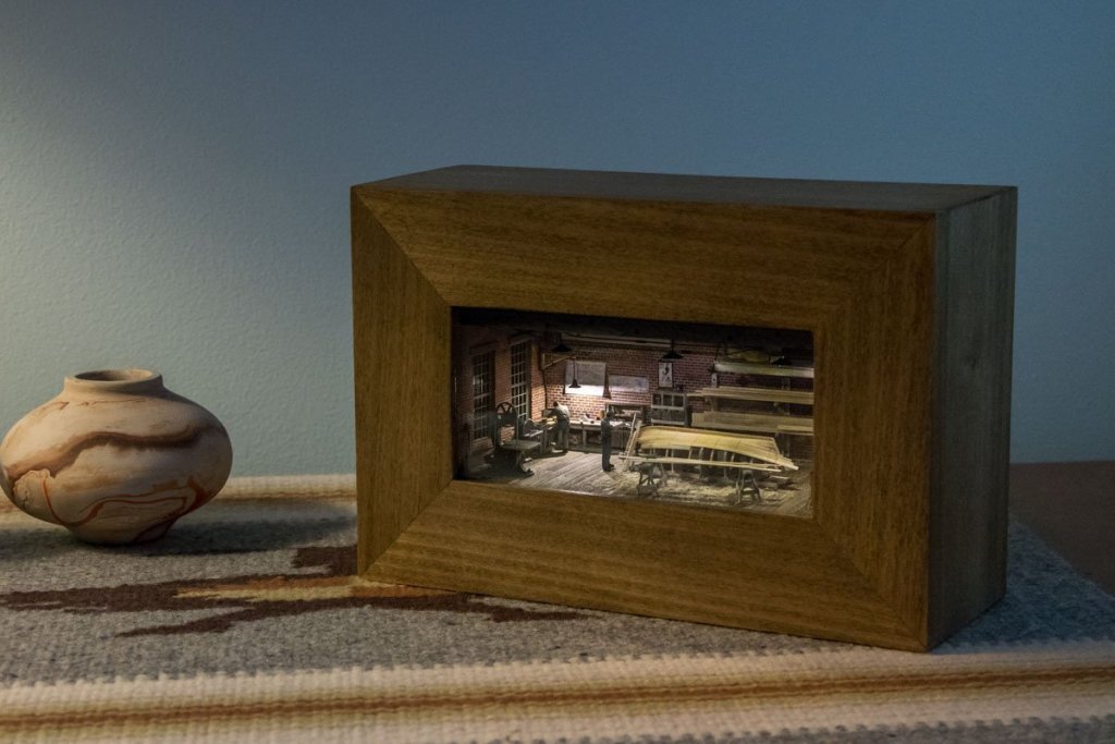
This post is unrelated to my Stonington dragger build and is just something I wanted to share. I hope this isn’t bending forum rules too far. I’m in the process of building a series of small shadow box dioramas in 1:87 scale. Each diorama is 2.25” x 4.75” with a maximum depth of 2.5”. The exterior dimensions of the shadow box is 8” x 5.25” x 3” deep. It is made from poplar and assembled with biscuits. This is the second diorama I’ve completed and depicts the interior of a small fictitious boat building shop. It is completely scratch built with the exception of the following items: The brick wall material is from New England Brownstone Co. in Massachusetts. It is made in white Hyrocal slabs that you cut and color as needed. The window frames, truss rod queen posts, turnbuckles and the 55 gallon drum are unpainted injection molded styrene from Tichy Train Group in North Carolina. And the two human figures are from Preiser in Germany. I apologize for the quality of these images as they were shot through the glass using a polarizer and only diorama LEDs for lighting. The exterior photographs visible through the windows were scaled and affixed to the inside of a PVC pipe that was split lengthwise creating a concave image plane. This means there is no upper or lower edge of the photo that can be observed. And because the photo sits back away from the window, the image shifts as the observer moves and their visual perspective changes. I installed two pushbuttons into the bottom of the case that control interior and “exterior” LED lighting. Being able to control them separately allows for day/night display scenarios and changes the mood - much more than I expected. Compare the “nighttime” shot below to the “daytime” (with interior lights on) shot above. And then exterior lights only. Interior lights only. Exterior lights only. And a couple of other shots. Thanks for taking a look – now back to the fishing dragger. Gary


- 424 replies
-
- 37
-
-
Wonderful work Frank - as close to perfect as it gets. Congratulations. I look forward to seeing your dredges and of course the final "studio" shots. Gary
-
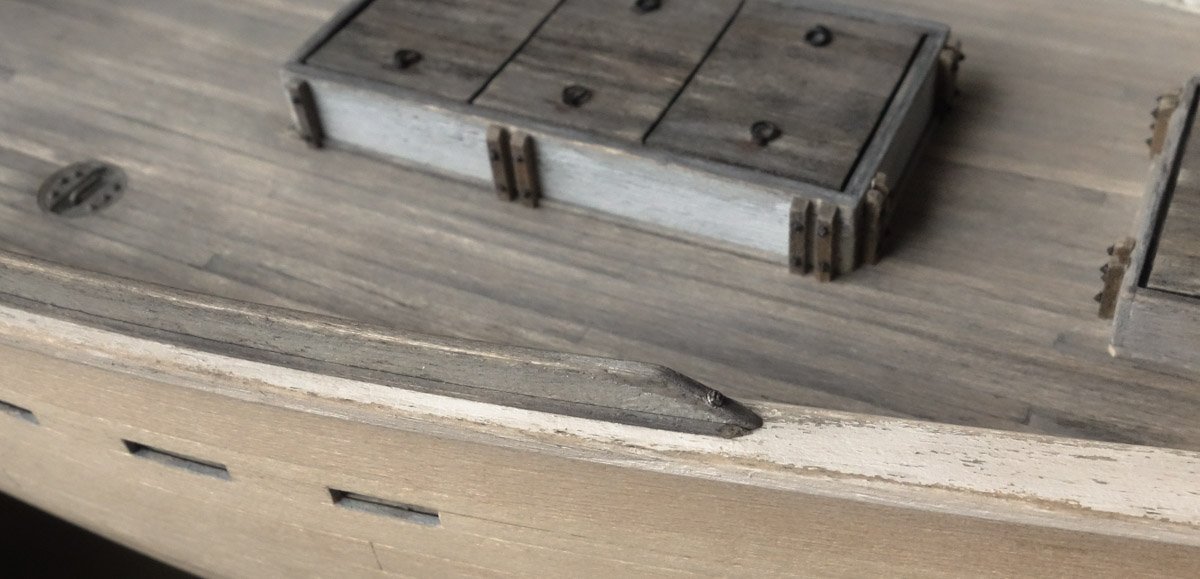
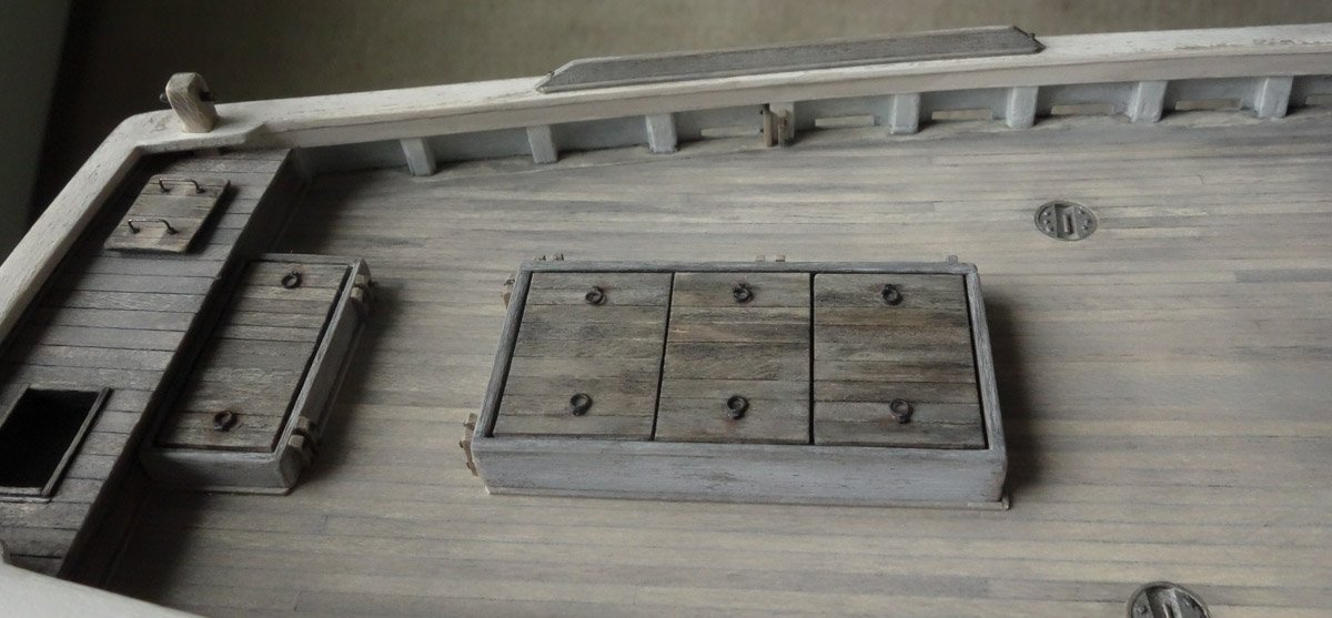
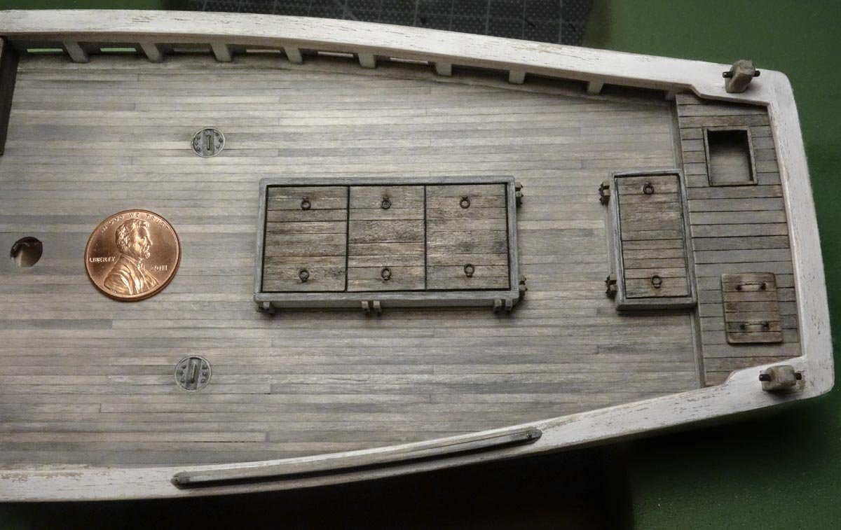
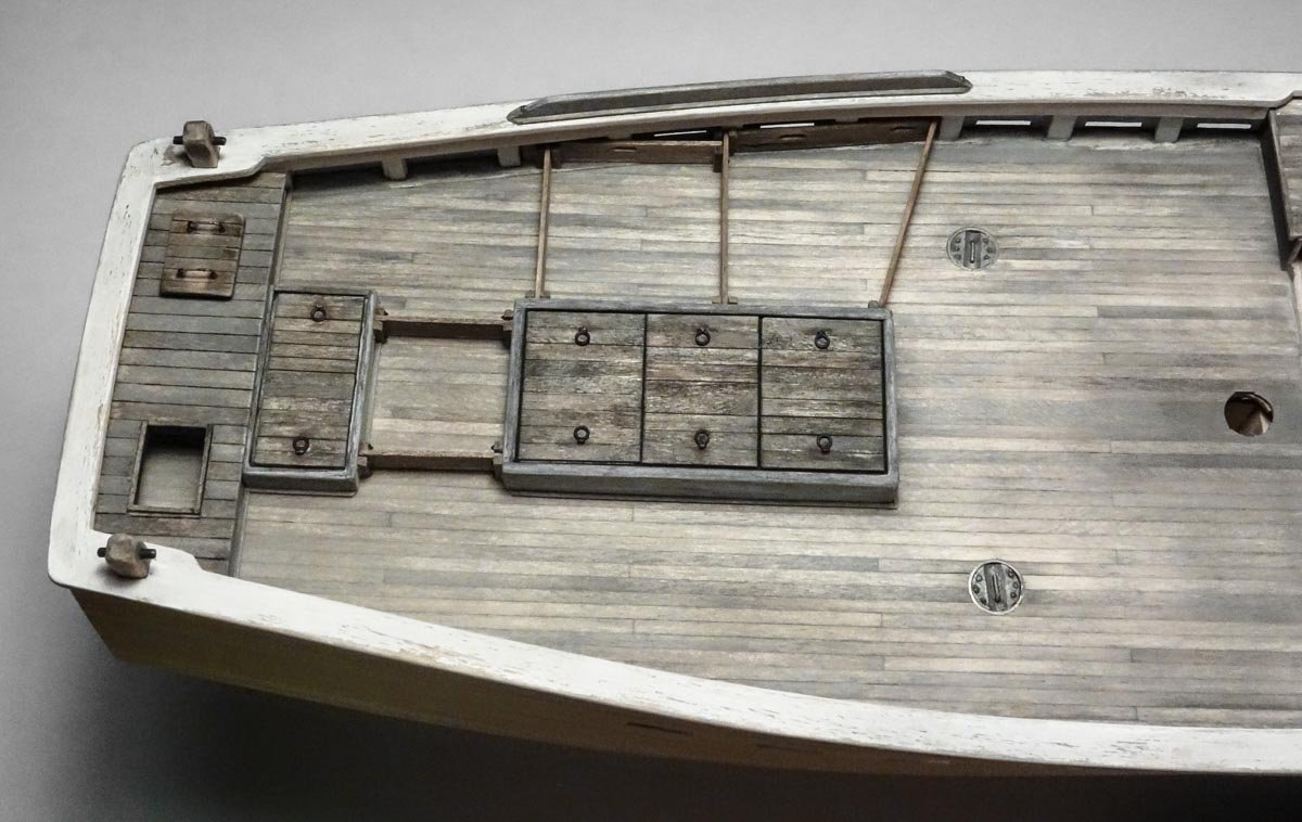
Keith, John, Druxey, Mark and Alexander - That you for your kind words and for looking in on my build. I appreciate it. Dave B - Glad that you find my log of interest, and thanks for the compliments. Happy to have you following along. And thanks to everyone looking in and hitting the like button. Some Deck Details This is a small update showing the addition of a couple of minor deck details: - Trim around the base of the fish and ice hatches - Two fish hold deck plates - Added rail to the port side The added rail shown prominently in the following 2 photos is a mystery to me. I don’t know what it’s called or what its purpose is. It is shown in nearly every photo of every Stonington style dragger I have seen. It is always on the port side directly in front of the sorting pens. - Is it to keep fisherman from flipping backwards over the rail when sorting fish on a slimy deck? It doesn’t seem high enough to prevent that. - Or does some kind of cleaning table set on or hook over it? I have not seen a single image that would even suggest this. If someone knows or has a theory – I’d love to hear it. Here are a few more photos. In this final photo a faint deck wear pattern is beginning to emerge. I don’t want to commit until the winch and gallous frame are built and placed. Next I'll be starting in on the pilothouse. Thanks for stopping by. Gary


- 424 replies
-
- 20
-
-
Fairing is so time consuming and your results look very nice John. Looking forward to watching your build progress. Gary
-
Hello Dan. Sorry, these are the units I was referring to. Gary
- 238 replies
-
- 4
-
-
- leviathan
- troop ship
- (and 2 more)
-
Very nice work on this cross section Dave! You have some seriously great skills with the scroll saw and the egg trick is one to remember. I look forward to your future posts. Gary
-
Simply beautiful Kortes. The color tone on all your woodwork is so rich - very appealing. Gary
- 306 replies
-
- 3
-
-
- schooner
- la jacinthe
- (and 1 more)


.jpg.27093a8301ff6aef4d08562d84c8f37c.jpg)