


garyshipwright
-
Posts
916 -
Joined
-
Last visited
Content Type
Profiles
Forums
Gallery
Events
Posts posted by garyshipwright
-
-
I just picked up one at Harbor freight yesterday and been playing around with it. It seems to be a good one, but time will tell. I have a 12 inch chop saw which I use as much as my table saw so figure that this little chop saw should fit in really nice. Now all I have to do is figure out how to make it a little higher so I can see what am cutting. Maybe a table on top of the table. . Gary
- mtaylor and thibaultron
-
 2
2
-
Hi Druxey and Mark. You may be right druxey. Does seem that Montagu dimensions are different which keeps one on one's toes. Mark you are probably right sir. When you look at it, the cove doesn't seem to exist, the part that's right above the upper window's, which looks like curtains that go all the way across and unlike others such as her sister's which had good looking stern's. Her's looks a little on the flat side. ;o} O well, at the moment am having a blast and its nice to hear from you guys. Thanks for your respone. Gary
-
Hi Mark. Thank you sir for responding and does give one something to think about. Doing my research on the stern I found that model's of the Warrior and the Canada both 74's, have a taffrail fiferail. If you look at the plan its not there which doesn't mean much, that is untill you see the model which does show one. you will see that it has the fiferail but seems on the plan of Alfred her self doesn't show one. I do believe these plans are as build but not sure why the Warrior has one. Hahn didn't add one because it doesn't show up on her plan. Went through the plans and seems that there was more ships that had one then there was that didn'tll seems like there is a reason and hope to find out. . Gary
-
Hi every one. Just a quick question. It has to do with the taffrail and its height from the top of the keel. Steel gives the height of the taffrail at the middle, of 50 feet 6 inches from the top of the keel, are they talking about the trim also that goes around the top of the taffrail ? The reason I ask is in Steel plate he shows the taffrail fiferail which is setting, guess wise 6 inches higher, is this included in that height. Where does the taffrail starts and where does it stop? Thank you. In the mean time I check a few more things to see what I come up with. Gary
-
Hi Mike and Oskar24. Mike will do on the photo's sir. Oskar If I understand right Alfred and a few others are building Plank on frame like the real ships back then and the other method I believe is plank on bulkhead, which a lot of people builded. I believe that plank on frame is harder due to building up frames and other internal parts of the ship and plank on bulkhead is that the frames are plywood bulkhead installed on a keel and then planked on the outside once the bulkheads are sanded to accept the planks. There is a lot more to both types of building depending on were your interest ln the two. I have seen some really good Plank on bulkhead, but my interest is trying to build them like they was. Hope this helps. Gary
-
Hi Mike. Thank you and will do the same. How is your Agamemnon coming? If there is any thing I can do let me know sir. Seems like its been a long time. Gary
-
Thank you good sir. Gary
- Kusawa2000 and mtaylor
-
2
-
-
2 hours ago, SJSoane said:
Thank you, Amalio, for your kind thoughts. I have mostly learned from books and especially from the great modellers on this site. And a lot of mistakes!
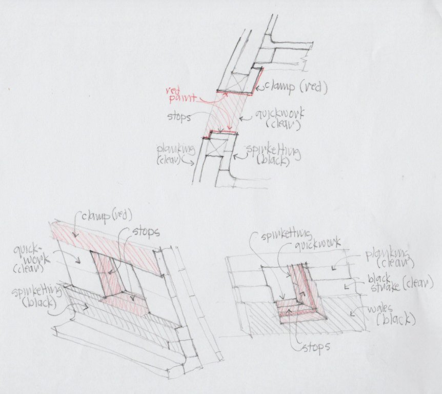
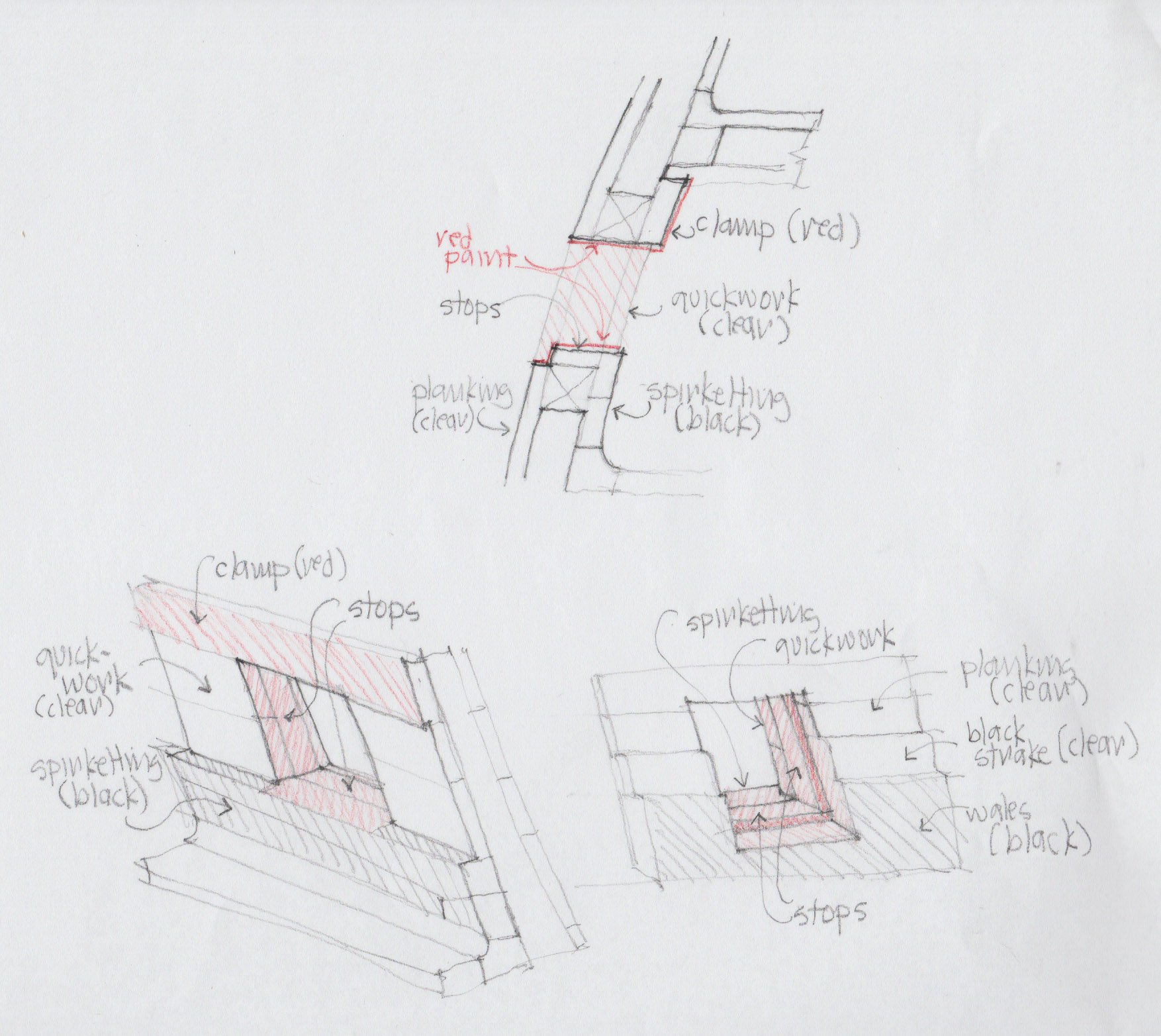
I am having to carve/shape the last two planks, and while taking a break from this, I looked more carefully at where paint/stain will meet edges and surfaces around the gunports. I have drawn a little sketch to think this through. I was surprised to see that the red paint comes over the top of the spirketting, meeting the black of the spirketting on a scribed line; and where the wales cross the last two gunports, I will have the black of the wales meeting the red of the gunport on the edge between the two, on the same piece of wood. And, the edges of the clear outboard planking will meet red paint on their outside corners at the edge of the port. These are the real test points of whether stain will work, or whether I need to edge these points with paint matched to the red stain elsewhere. Now I know what my test pieces need to look like.
Mark
Hi Mark. Nice job sir and I must say your drawing our outstanding. Mine comes out looking like a first grader in art class. Keep up the good work sir. Gary
- minimini, mtaylor, aviaamator and 2 others
-
5
-
Hi Mark. how about air brushing the paint on. Tape up what you don't want paint on and spray on the paint. You can also cut in above the tape edge and it will stop the spray paint from seeping below the tape. Works good for me. You can even paint dye this way. Practice on scrap till you get it they way you want it. As they say practice makes perfect.Here is a space shuttle I painted and built from a kit. I think it came out not to bad. Gary

- Archi, Wintergreen, dvm27 and 5 others
-
8
-
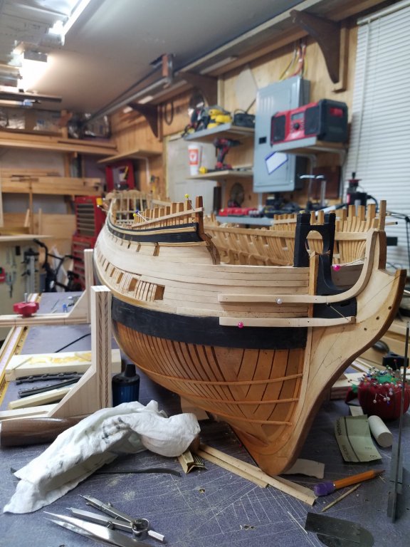
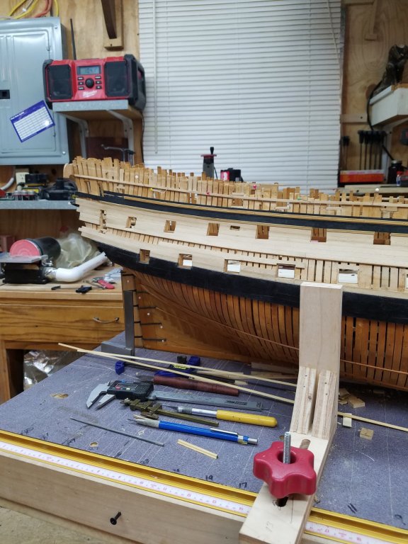
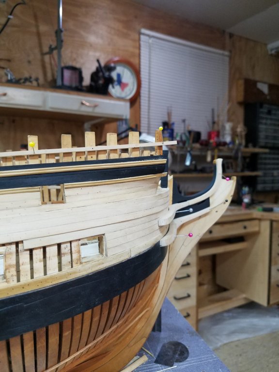
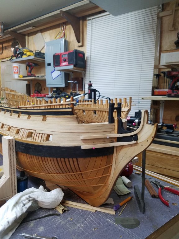
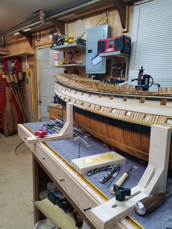
Hello Everyone. Seems its been awhile but some times life hits you between the eyes but I did get a little bit down on Montagu. Hope you enjoy the photo's. Gary


-
-
Hay Mark. Your doing good sir and druxy I do believe that model ship builders are some of the most humble, just look at their scrap box. Gary
- Hubac's Historian, druxey, mtaylor and 1 other
-
4
-
Hi Siggi. Went looking in the library and only came across two, one that shows the joint and one that talks about the hook and butt joints. The book 18th Century Shipbuilding, remarks on the Navies of the English and the Dutch, by Blaise Ollivier,1737 done by David H. Roberts and published and distributed by Boudriot. The other is The Anatomy of the ship The Bomb Vessel Granado1742 by Peter Goodwin. On page 52 he shows in figure 6/3 through6/6 the make up of Granado wale made up of 3strakes showing the upper and lower put together like your bottom drawing. Some would say the Anatomy of the Ship is full of mistakes, which I have found some but doesn't stop me from using what I think is right as long as you can back up what your using.I look and see if I can come up with some more for you. It also shows that the middle one as just having a butt joint. Gary
-
-
-
Hi Sigi. Nice job on the ports sir and seeing your work am sure they will come out just as good as the ones in the photo. As far as gun ports I just finished up the ones on Alfred which has taken me a while to do. Hum come to think of it 17 years. ;o). Look forward to seeing your next update. Gary
-
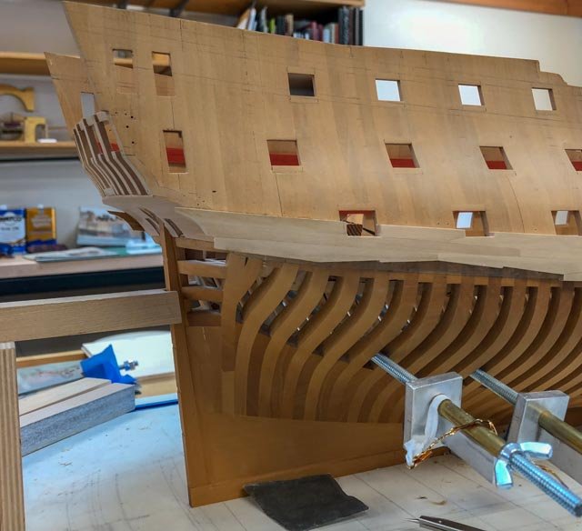
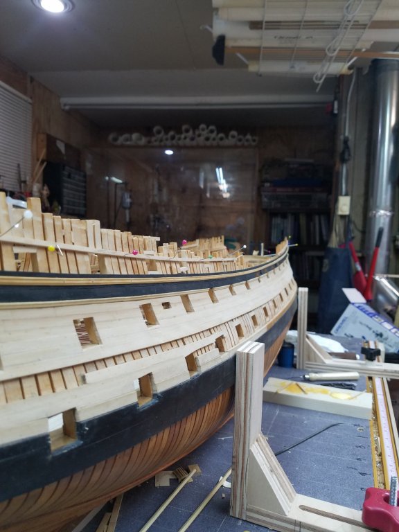
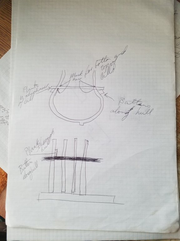
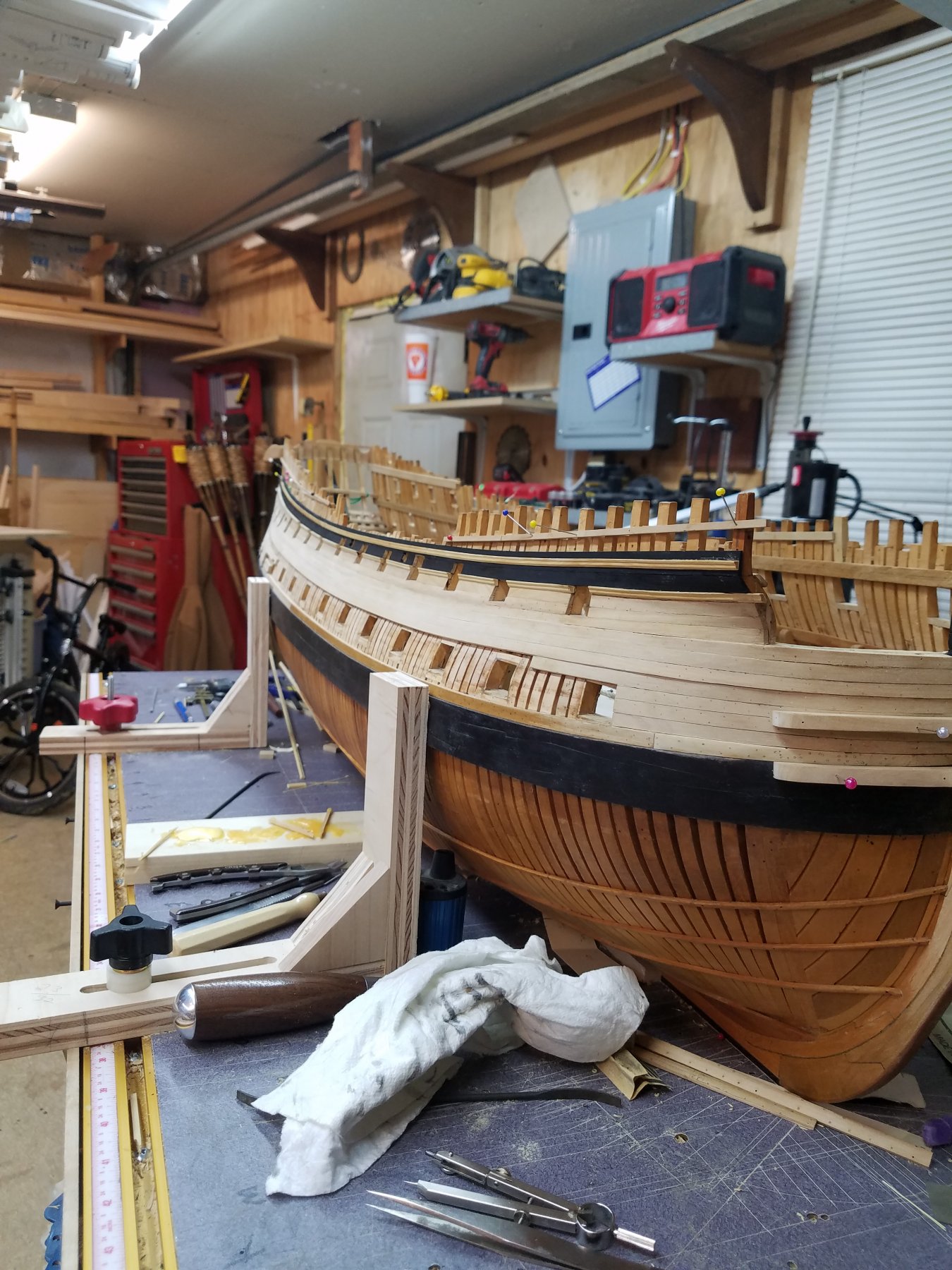
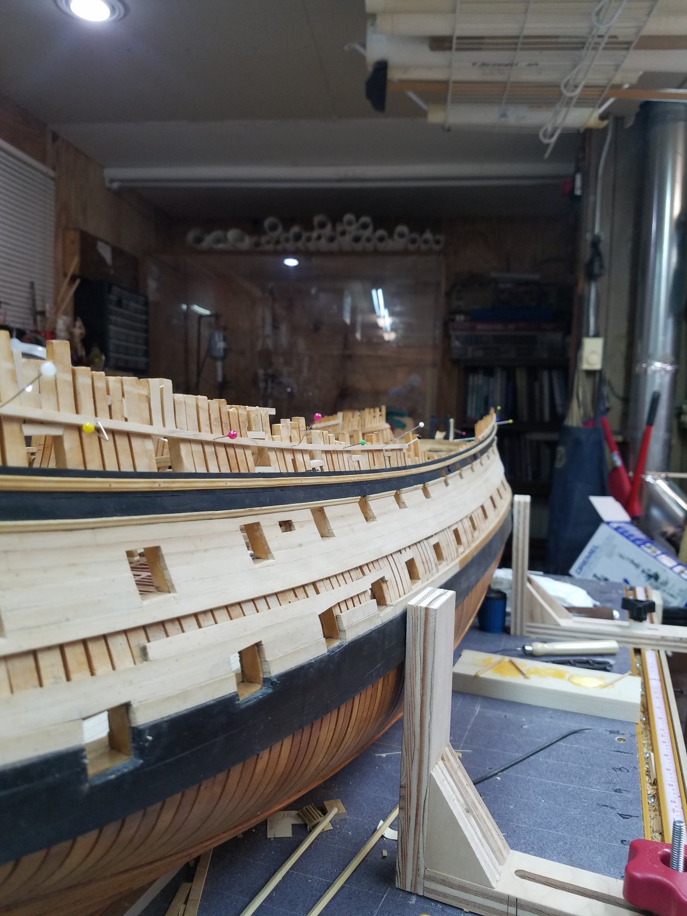
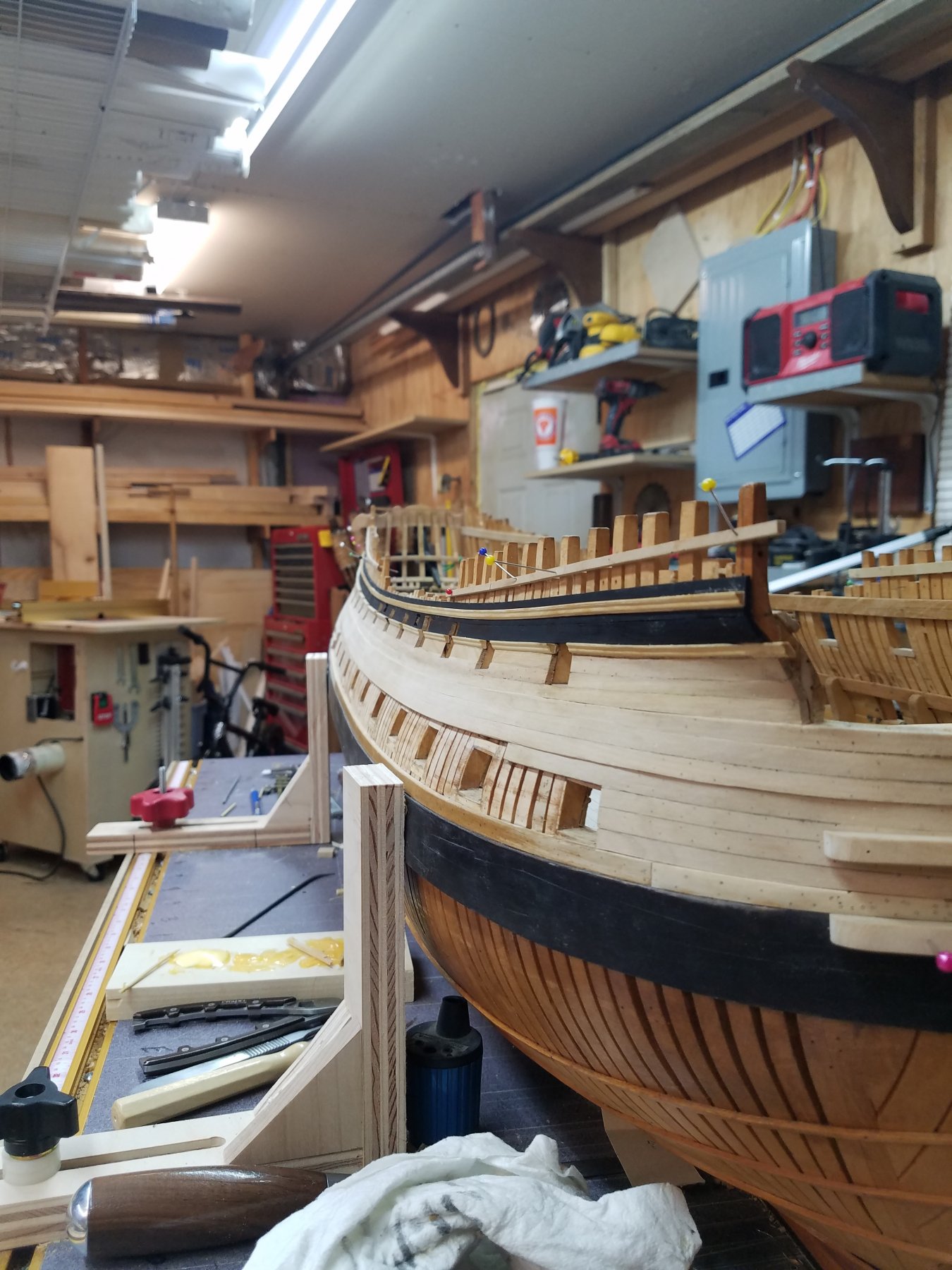
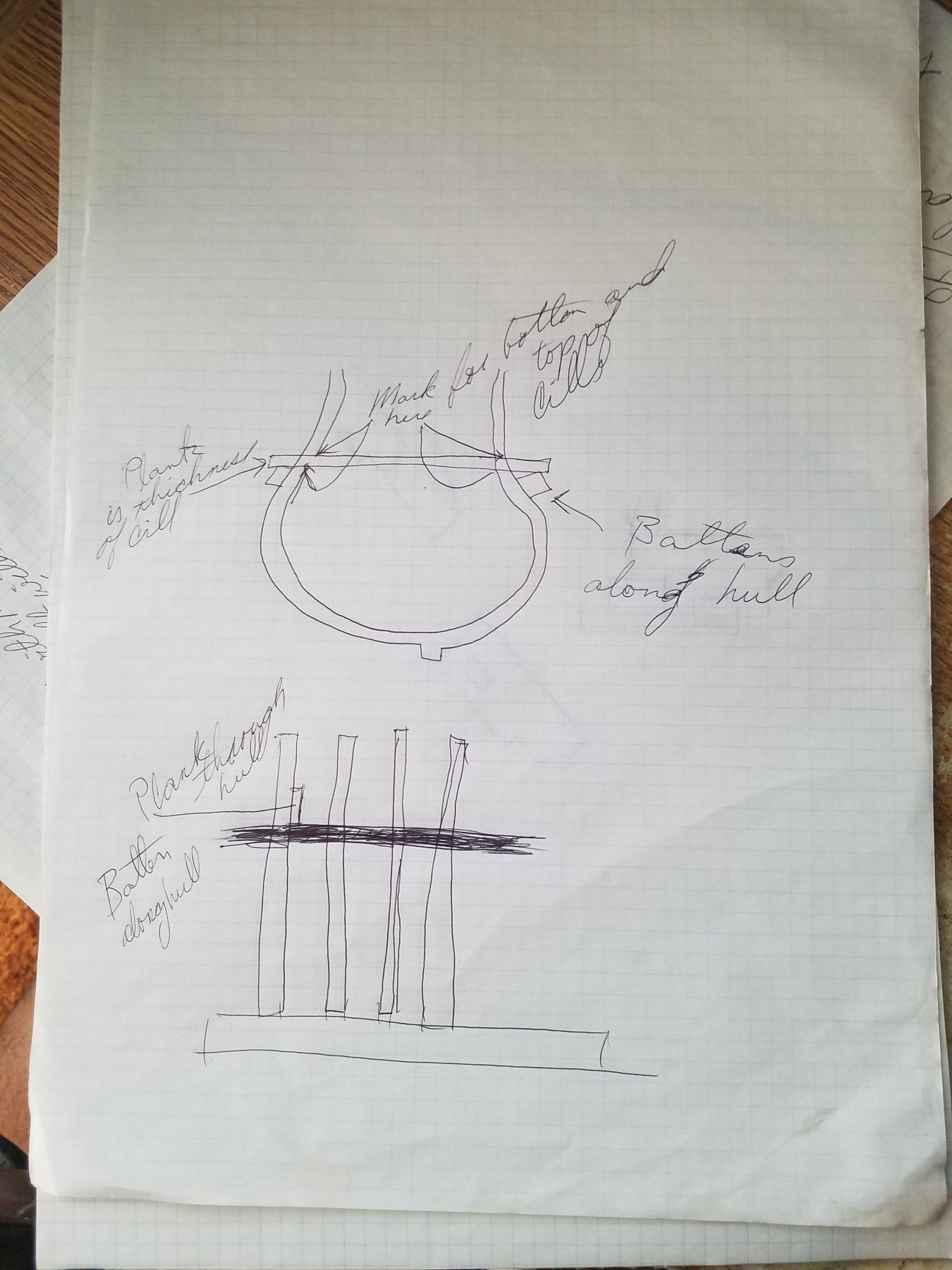
Hi Allan. Thought I would give you my way of how I did the gun ports on Alfred, which may help you and give you some ideally's that might help when it comes to getting your ports right. What I did with Alfred is completed all of her framing and sanded the hull to shape and made sure every thing was right with her framing. I just could not see cutting out the gun ports as the framing was being put together. To me there is just to many varables to contend with in getting the ports just right from the stern to the stem. Once I was happy with her hull and she had the gun deck and main wales in place for strength, figure it was time to work on the ports and was worried about not getting them right. After marking off the upper and lower cills along the hull, I took a batten and pin it in place on those marks along the hull giving me the lay out of the cill's. You can also use the gun deck clamps to help in laying them out height was, but found that using the base board a better place to measure from. What I also did was put those battens lower by the thickness of the cill and then made up some planks to fit the spacing of the frames,and went from side to side that was the height of the port from the bottom cill to the top of the upper cill. You can also make the planks the size of the cills them self and use that to set on the battens to mark out you cills. Then one can mark the inside of the frame with a level line on both sides showing were the cills will lay. If this doesn't make sense let me know and I see what I can do to make is make sense. Hope this helps. Added a photo sir, hope it makes sense and forgive me for being long winded. Gary
-
Well hello Siggi. About time you get back to work and I do believe you have another master piece in the works sir. I still look at your Dragon just to help on the stern of Alfred. Love the figure head and hope I can do Alfred's carving as well as you have done you Lion. Will be watching sir. Gary
- Alexander B., mtaylor, CaptainSteve and 1 other
-
4
-
2 minutes ago, druxey said:
Earlier ships had beveled steps as shown, later ships (after about the 1830's) had a smooth surface where strakes tapered into one another. The main wale was then not stepped at all.
Hi druxey. You are correct sir. If one looks at the photo from Finchams book you can see that the planking from the main wale down is blending with the bottom strakes with no step in between. Gary
-
Hi Mark. You could be right sir but if you look at the photos of the model of the Bellona her self in the Gallery you will see that the planking between the first black strake and the rest of the planking up to the channel is different. Being that the short planks between the gun ports all look the same. They could have taken off the upper edge's of the two in the photo but could this have been done to do away with the sharp edge of the strakes them self. Not to be nit picke, seems that Brain drawing is missing a strake in the main wale. Could of swore there is four. Thing is if you taper the black strake in to the other upper planks are you not doing away with a detail of her? On a different noteI have added a photo of the contract that am using to help me build Montagu and a plate from Fincham's Ship Building, reprinted by the Ship Model Society of Rhode Island, 1933, that show the step down from the black strake up to the channel wale. Either way sir Bellona will still be one outstanding model's no matter how you do this. Gary
- albert, aviaamator, mtaylor and 3 others
-
6
-
-
-
Hi Mark. I do believe he is right about there being two but I only read or heard that the one on top of the main wale was refered to as the black strake. Any way I have the contract of the Marlborough of 1763 and says that the black strake was 13 inches wide and 6 1/2 inches thick and the one that was on top of that was 5 1/2 inches thick. From what I understand and reason that one might think there is only one black strak is due to the second one being blend in with the other planks that sat on top of it that ran up to the channel wale, which was reduced down to 4 inches. Also just a word of advice, once you get your main wale done install your channel wale or at least ran a batten for the bottom of the first strake of the channel. It will help you out in getting the planking from the main wale up to the channel right and looking good. Wished I had down this before installing any planks above my main wale. For me a lesson well learned. The measurement of the channel is 2 foot 9 inches board by 5 1/4 inches made up of 3 strakes, unless your plan shows it being wider. You should have 5 strakes between the main wale and the channel wale which includes the black strake.
Gary
- mtaylor and Landlocked123
-
2


Chop Saw from Harbor Freight - Review
in Modeling tools and Workshop Equipment
Posted
Hi Bob. The protractor sounded like a good ideal so I order on and should be here early next week. Should really make the chop saw a whole lot more accurate. Thank you. Gary