Hubac's Historian
-
Posts
3,317 -
Joined
-
Last visited
Content Type
Profiles
Forums
Gallery
Events
Everything posted by Hubac's Historian
-
 Yes, I can see that aspect of your dillema, now - the accumulation of color in corners and how that would be especially apparent around the rigols, for example. It seems to me that the antique wash coat will help a great deal with that issue, and I like that you will “dirty” her up a bit, as anything that goes into the sea does not remain pristine for long.
 -
Whatever inconsistencies there may be in color tone, they don’t show in the photographs. Though these are diluted wash coats, I would think the color would even out after a certain number of applications. If not four wash coats, maybe 6? Perhaps, also, making up a large enough batch of diluted paint to do two to three wash coats from the same batch, might improve the consistency of the color.
-
You are welcome! I often say the same thing about the talent and collective IQ on this site. I have and continue to learn a great deal from all of you. Happy Friday!
- 1,035 replies
-
- 7
-

-
- royal katherine
- ship of the line
- (and 1 more)
-
Hi BetaQ, The following link is to a really excellent modified build of Heller’s Le Superbe. He used ModelSpan tissue to make his sails, whicch is excellent for smaller scales. He provides a fail-safe tutorial for his method, which I think is quite Superbe!
- 1,035 replies
-
- 9
-
-
- royal katherine
- ship of the line
- (and 1 more)
-
Hey Vic and Mark, thank you for your kind words and comments. And a hearty thanks to everyone else reading along and for their likes and comments Vic, you raise an interesting question concerning at what point an existing product has been sufficiently and substantially modified to become a new, independent product. I suspect that despite changing the dimensions and profile of the upper bulwark pieces, as well as, clearing away 85% of the moulded detail - I suspect that what remains is still substantially and recognizably a Heller product. It is an interesting question, but not one that I have any interest in pursuing. My hope was to inspire others to take this kit and apply their own interpretation of primary sources; to, in other words, kit-bash the hell out of it and see what they came up with. What remain my intellectual property are the carving masters that I am making to embellish the kit. I suppose that, if someone really wanted them, I could make new rubber moulds from those masters, for their own use. I would hope, though, that most would want to take a stab at making their own carving masters and castings. I hadn’t done it before now, and the relative success of it really propels the project forward. It is what makes all of the truly tedious stages like scraping off perfectly nice existing detail, or building up my sheer railings worth it. Because I now know that I’ll be able to put my indelible stamp on the kit, just as I drew it on paper. Nothing about this will be perfect, but it will be mine. As a side note, I have begun taking small-work to work with me. I have a union sanctioned break and a decent lunch time with which to get something done, and most days I do. This is so much nicer, in the day, when I’m fresh. Little by little; incremental progress day by day. It’s been a couple of years now, since I started drawing and modifying, but when I look at how the parts have transformed, I am amazed by the progress of the project. I’m glad, now, that I didn’t wait around for a “better time” to get started. I’m also glad that Dan Pariser persuaded me to start a build-log. The log, itself, is a huge motivator. Thanks, again, Dan!
- 2,699 replies
-
- 3
-
-
- heller
- soleil royal
- (and 9 more)
-
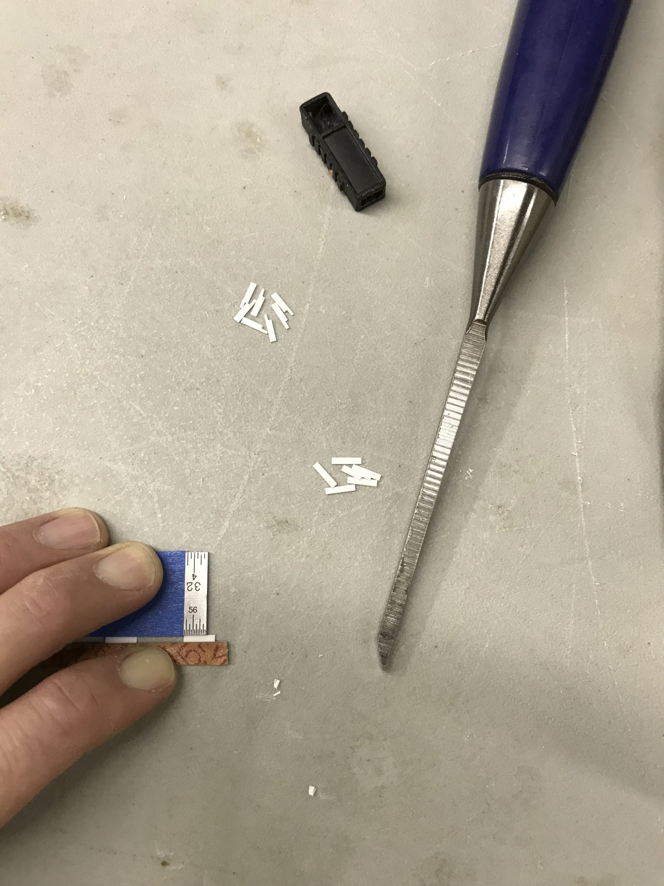
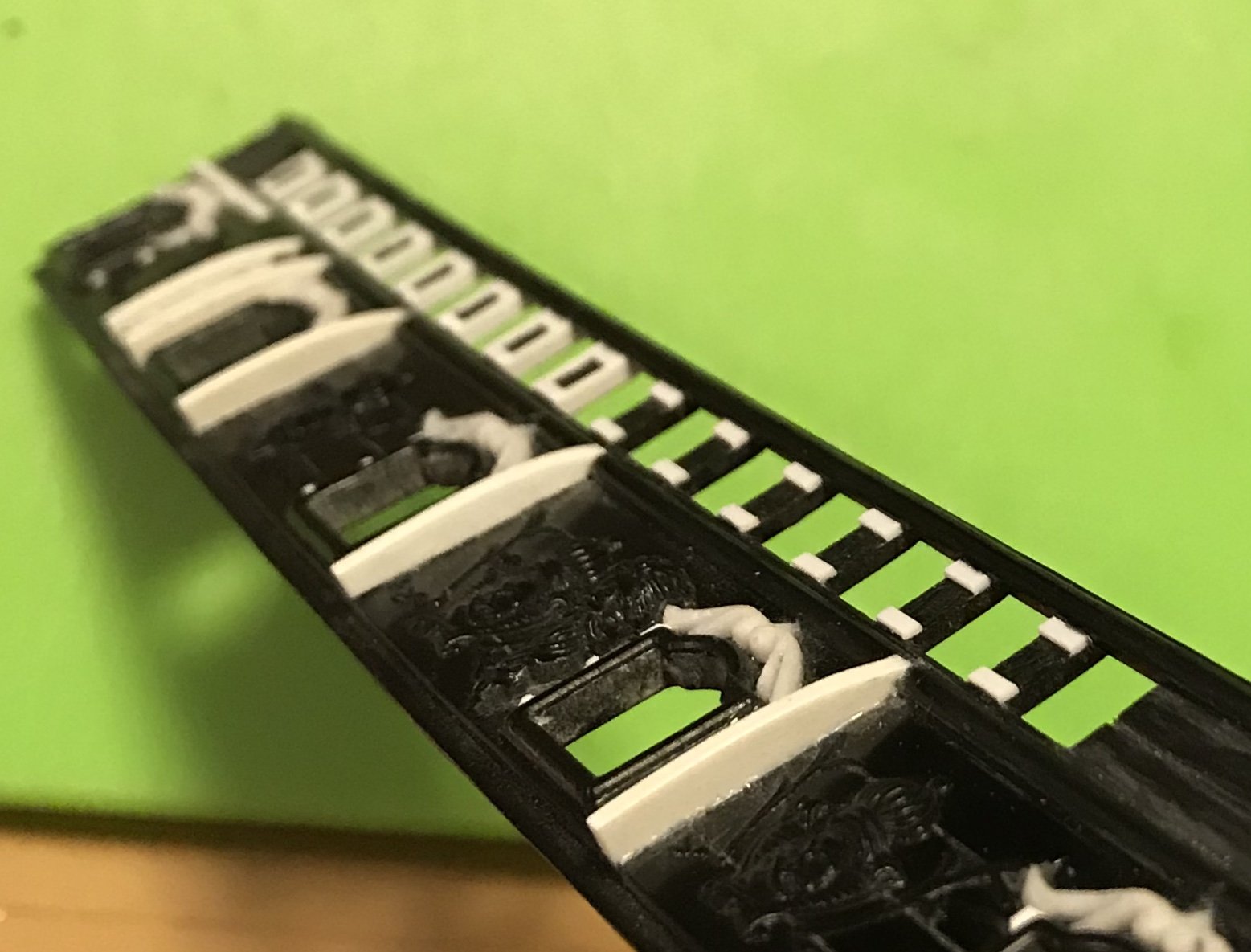
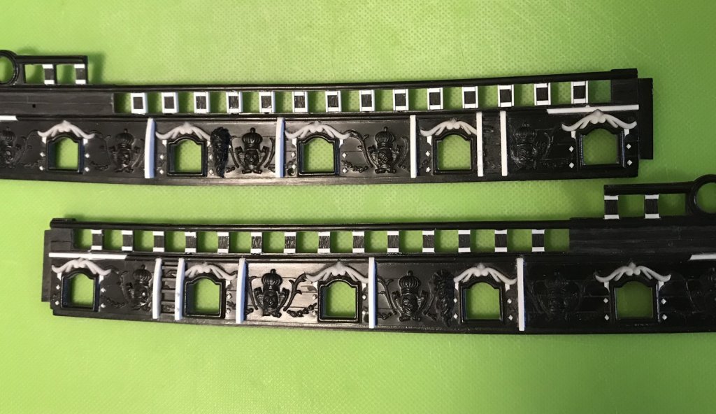
My decision to continue this frame and panel motif through the waist rail will, ultimately, be worth the effort. The project is not without its challenges, though. Chief among them is finding some way to neatly and uniformly cut stepped haunches into the vertical framing elements, so that they tuck neatly around the sheer moulding, itself. The parts are so tiny, that they can’t really be held and worked with your fingers, alone. My solution was to use blue tape to mark the shoulder of the haunch onto a steel ruler, and to then pinch the part between the ruler and an emory board, using a spacer block in-line with the piece being cut. I could then use my free hand (holding the 1/8” chisel blade like a pen) to make a series of shallow waste cuts, lengthwise, before aligning the back of the chisel blade with the edge of the ruler, to cut a square shoulder for the haunch. Just as you would for any other repeating part, I had to do a few test pieces, in order to get the dimensions right. Once I had it, though, the pieces fit snuggly along the length of the waist rail without additional fiddling. What you see, here, has not yet been leveled and a spot of filler, here and there, will be necessary. I just think this gives much better dimension to the timberheads and gives the whole thing a more finished appearance, befitting of her stature as a Capital ship. In other news, casting continues alongside this little project, and my castings look good and clean.


- 2,699 replies
-
- 6
-
-
- heller
- soleil royal
- (and 9 more)
-
Wow, Canoe! Your wife must be the Queen of all unicorns; not only does she tolerate your shipmodel madness - she actually wants to be a part of making it happen. Congrats to you, my friend!
-
Hi Doris, I agree with you that the Vale painting is of little help in discerning the details of the tafferal. As ever though, you have done a masterful job of filling in the blanks. Magnificent!!
- 1,035 replies
-
- 8
-
-
- royal katherine
- ship of the line
- (and 1 more)
-
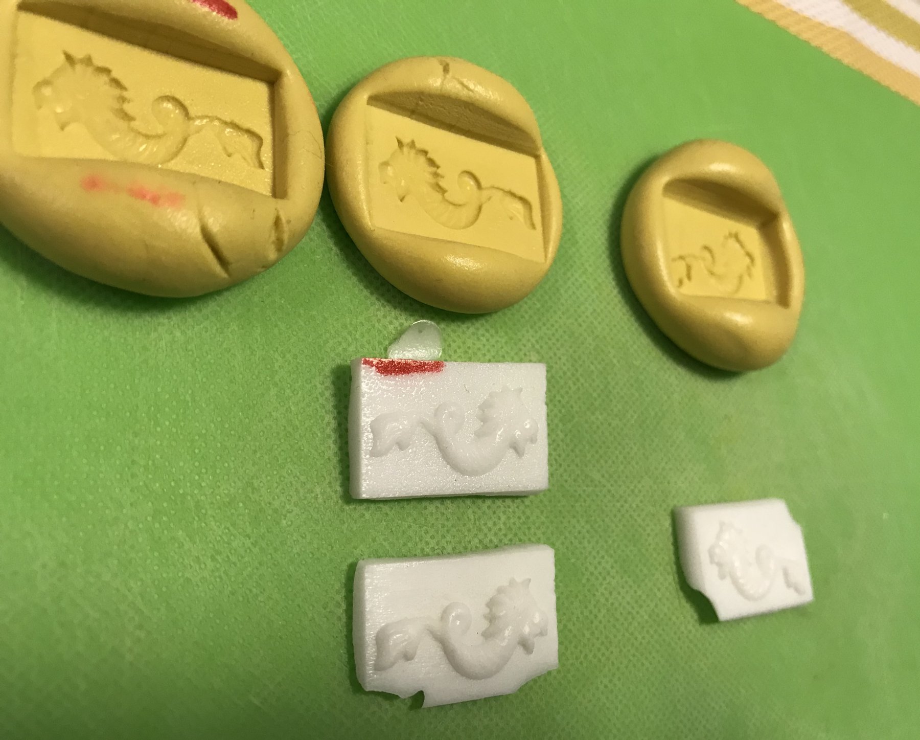
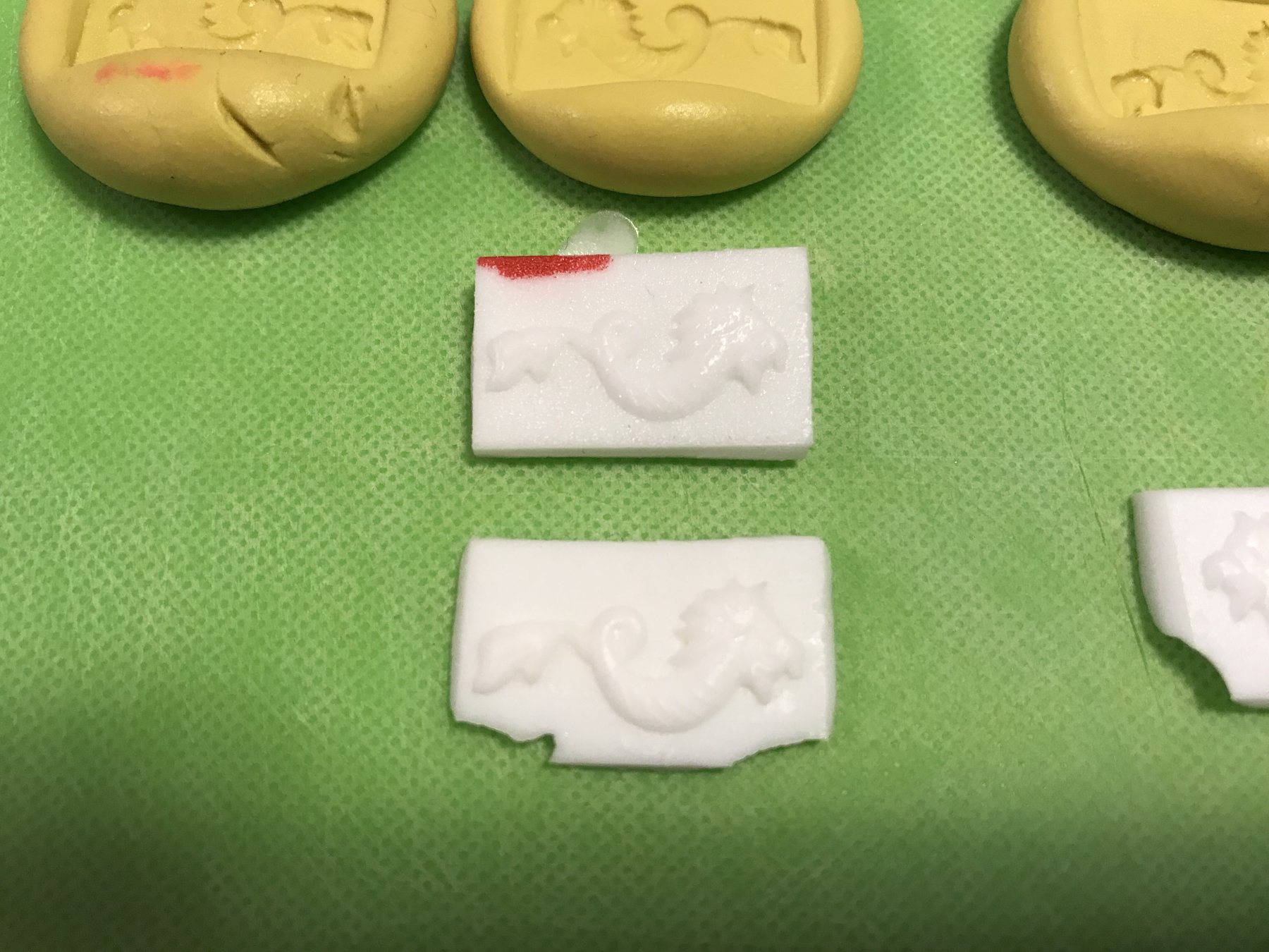
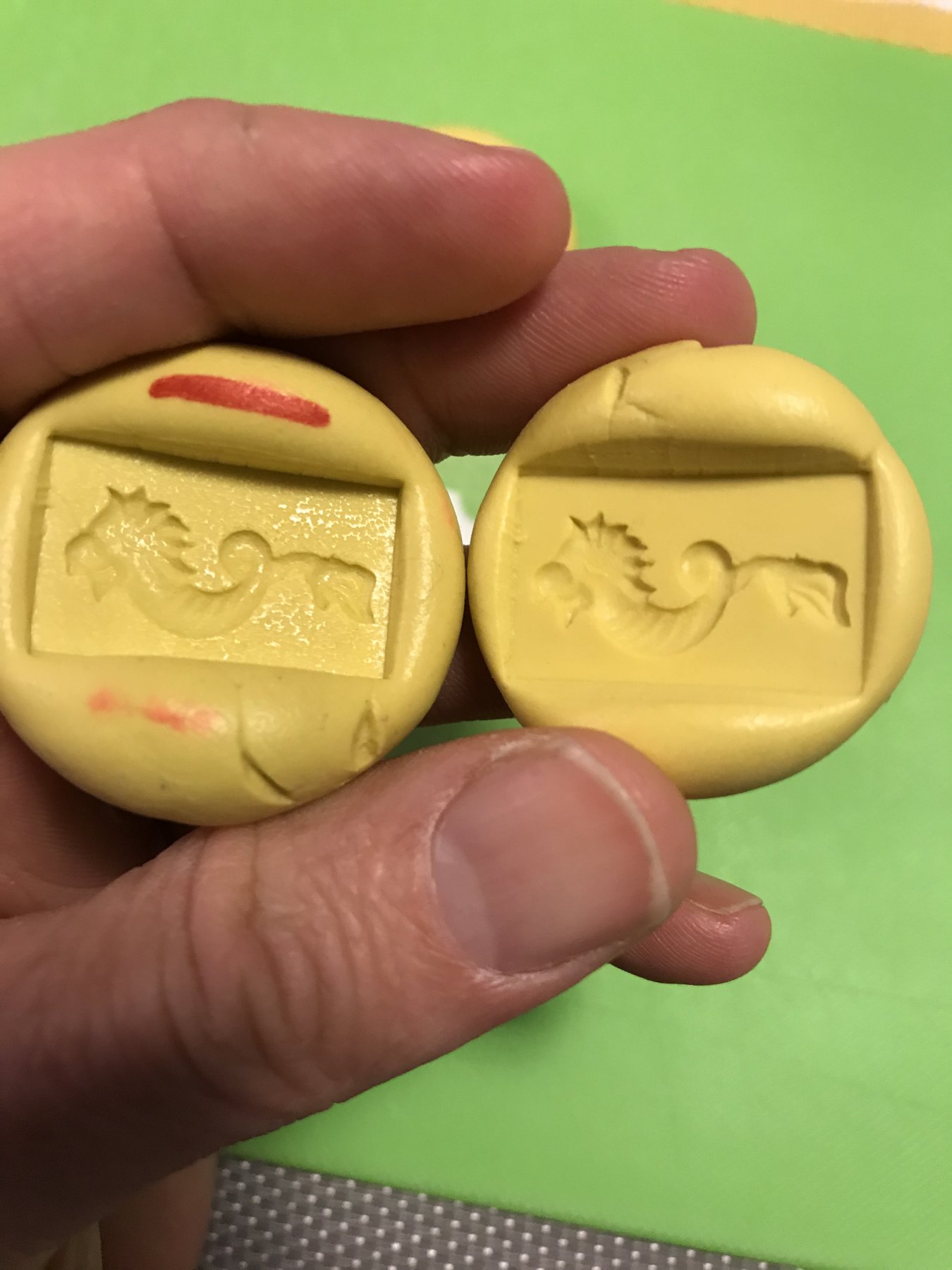
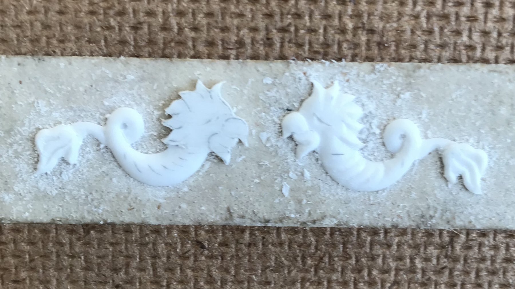
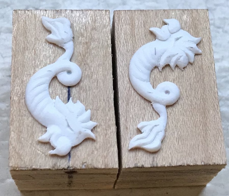
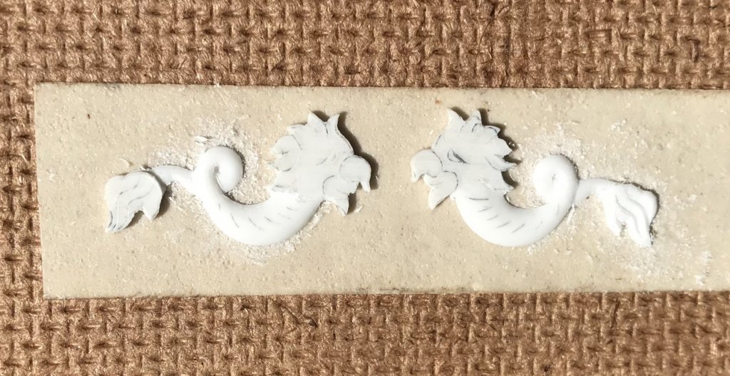
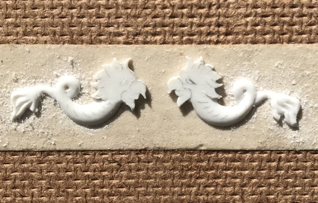
Okay, so here is an attempt to illustrate the first defective mould next to the much better mould. The defective mould and casting are marked in red, and on the left. My overhead lighting makes it difficult to really see how much of a difference there is between the first and second castings, but it is significant. This next picture shows the difference in the moulds a little more clearly. You may notice that both these moulds have “cracking” around the perimeter, where it does not impact the casting. I wonder whether this has to do with the age of the product; although I have kept the stuff in a cool and otherwise neutral location, it has been some time since I first broke the seal on the containers. My port enhancement moulds did not show this cracking. Maybe one has to skim off and discard the top layer of mould medium, if they haven’t used the product in a while? I’m using the “Amazing, Super, Marvillosa” mould putty.


- 2,699 replies
-
- 8
-
-
- heller
- soleil royal
- (and 9 more)
-
Hi EJ - well, one mould came out great and produced a relatively clean casting, but the other produced a kind of textured surface on the casting. I noticed that this second mould had some uncured residue of the mould rubber on it’s surface; I suppose that I didn’t quite get the ratio equal for the two-part mould medium. I’ll re-make that mould and try again. Will post pictures of the difference later. Yeah, this whole exercise in making miniature carvings is a real head scratcher. I like what I’ve come up with, so far, for this build, but the appearance of these castings will be significantly improved with paint. If I were making an arsenal model, in wood, I would strive for a more crisp and clean presentation because the surface is the finished product. If my resin carvings pick up some light and shadow, and show some visual interest, then they will be a success.
- 2,699 replies
-
- 2
-
-
- heller
- soleil royal
- (and 9 more)
-
Truly spectacular, Vic! I know how you feel about those old pirate movies. The studio model-makers, from those days, really did quite a job. I can't wait to see your Couronne cut through the sea.
- 213 replies
-
- 4
-
-
- la couronne
- 74 gun
- (and 2 more)
-
Or, not hopefuly. Maybe I’ll embrace better technology like these upstart, results-oriented Millenials . An amendment - having read this over - I still hope to live a really long time! Going for 9-0!
- 2,699 replies
-
- 2
-
-
- heller
- soleil royal
- (and 9 more)
-
Ha! I’ll be a 45 degree angle in August! Hopefully, plenty of scraping ahead of me.
- 2,699 replies
-
- 2
-
-
- heller
- soleil royal
- (and 9 more)
-
The carving continues; starboard side done, and port not far behind: Ready for central casting! The sides still mate nicely. I’ll be interested to see whether the casting resin holds the fine detail as well as I hope. I had to do a lot of re-work on the arched port enhancements, even though the carving masters looked eye-clean.

- 2,699 replies
-
- 7
-
-
- heller
- soleil royal
- (and 9 more)
-
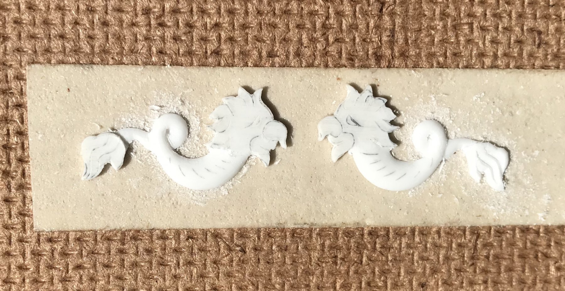
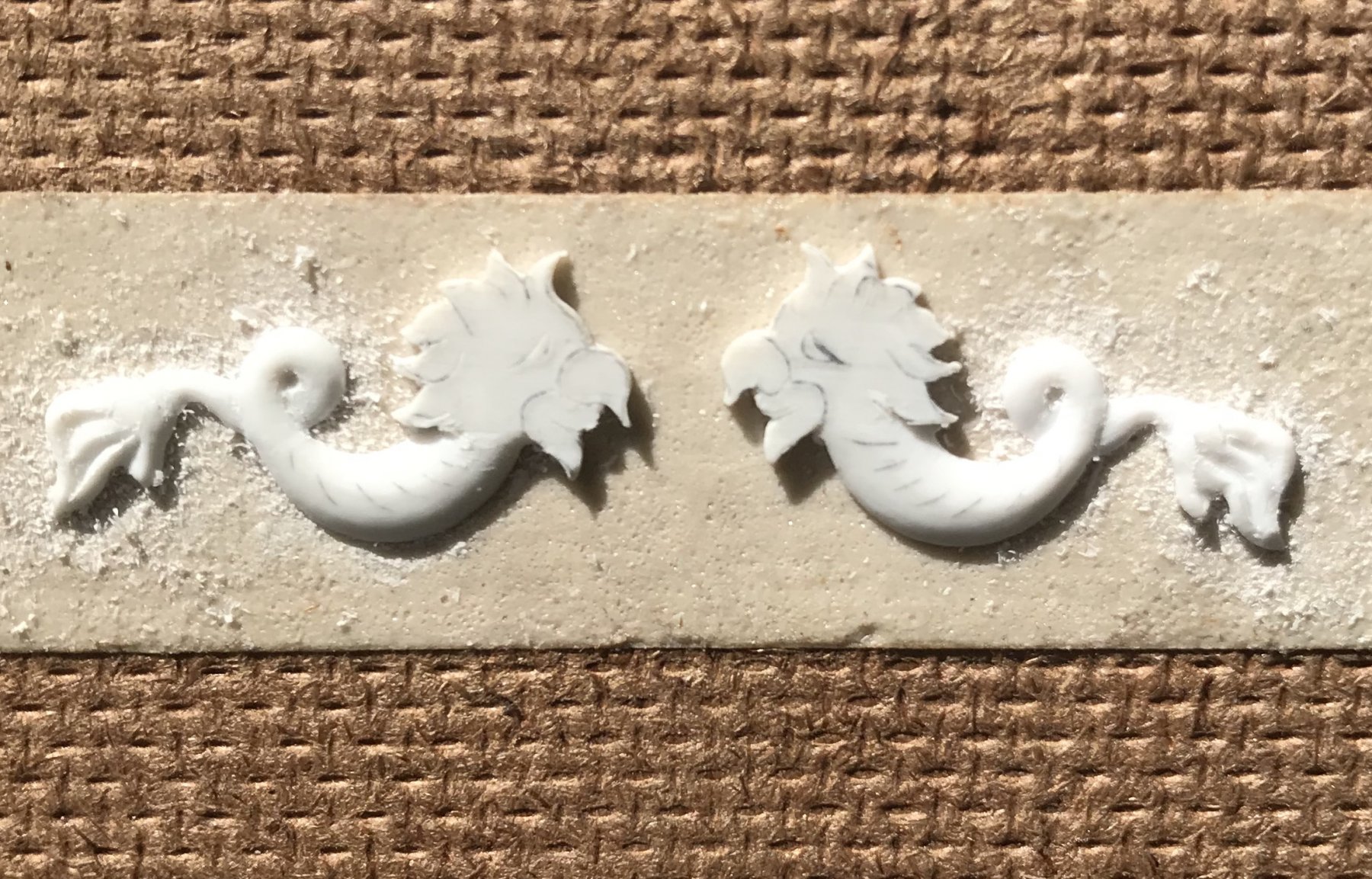
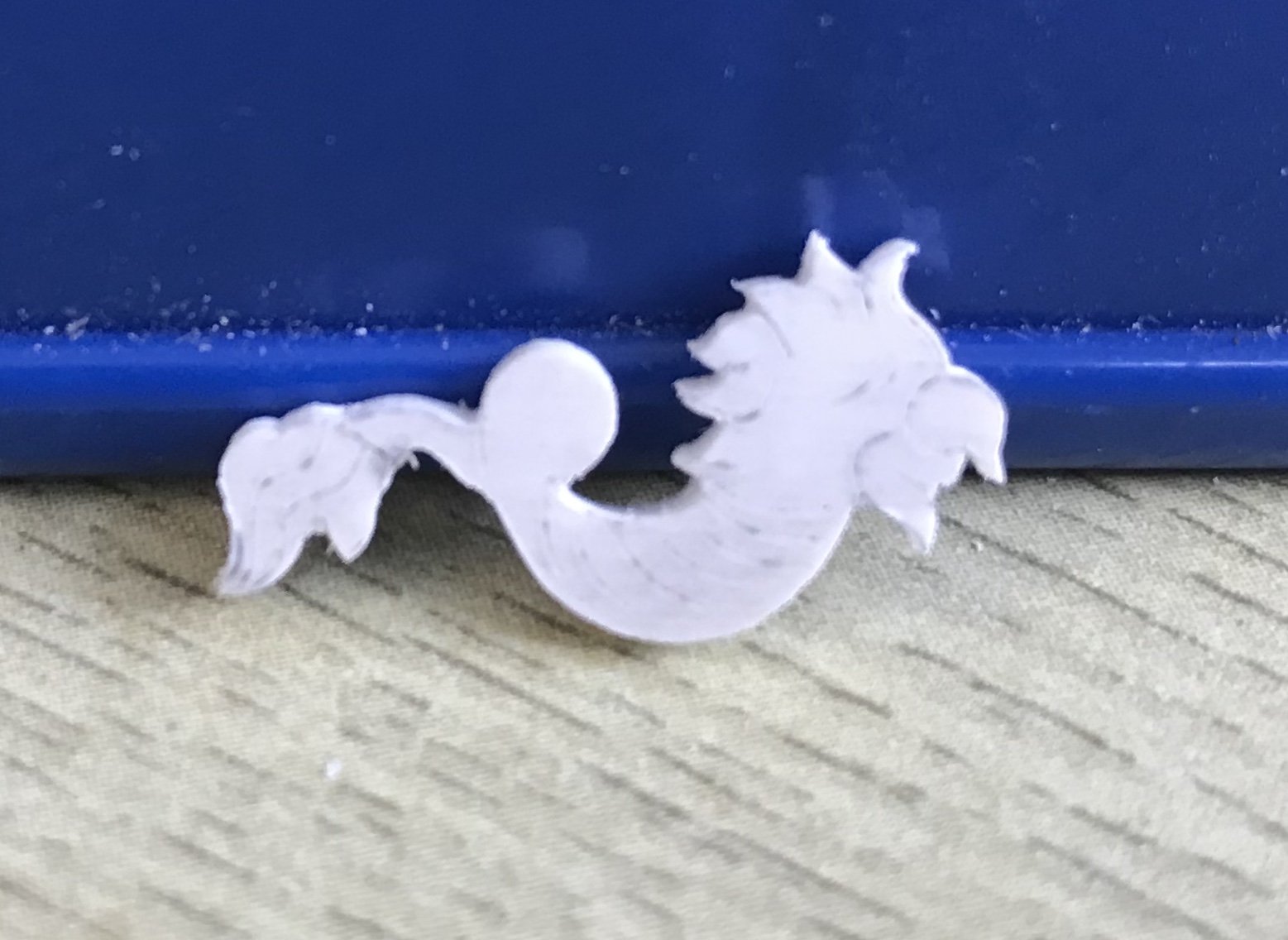
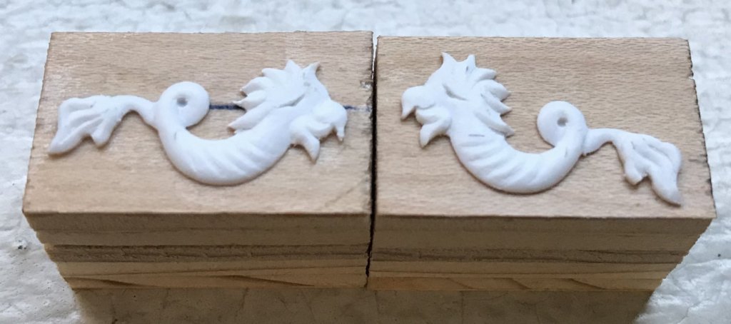
Just a few work-in-process shots to show the process of shaping and layering in detail: These dolphins, across, are roughly the diameter of a quarter. The tail detail does not perfectly mirror one side to the other, but it doesn’t need to. I’ve saved the trickiest bit - the heads - for last. The difficulty is that, at most, each dolphin half is only a heavy 1/32”, but you have to sink about half of that to delineate the beak/mouth. The eye detail will merely be a suggestion, at best, with a hard line delineating the brow. The hair is the “easy” part When the head is defined, I’ll go back to the body and add in the arced creases, just to give the surface some visual interest. Then, it’s off to casting!
- 2,699 replies
-
- 6
-
-
- heller
- soleil royal
- (and 9 more)
-
Hi Doris, Will you be making up the gun barrels from scratch with rolled card, as you have in the past, or will you use turned brass guns like the sample one on your quarter deck? P.S. I hope you get your mojo back soon.
- 1,035 replies
-
- 5
-
-
- royal katherine
- ship of the line
- (and 1 more)
-
Fine sable brush; good light; controlled breathing; quality acrylics; the willingness to take as much time as is necessary. Those are the ingredients of my technique. I used to be a pro at cutting right up to the ground without bleeding over. I want, for example, to paint not just the outward face of the wales black, but the top edges as well, for a better three-dimensional effect. The space between wales can’t really be masked with tape, so it has to be done by hand. It has been a while, since I did this, but as with most things in life - patience should carry the day. And, of course, there’s always a certain amount of retouching. I am curious to see how well Herbert Tomesan’s patinated wood effect translates to the raised, moulded grain of the Heller kit. Herbert’s models, while scratch-built plastic, are textured with coarse sand paper, and the darker wash coat gets into the scratches. It’s all an experiment, but it should be interesting. And I have plenty of spare plastic, in Henry’s donated hull and my own cut away hull bottom, with which to work up finish samples.
- 2,699 replies
-
- 2
-
-
- heller
- soleil royal
- (and 9 more)
-
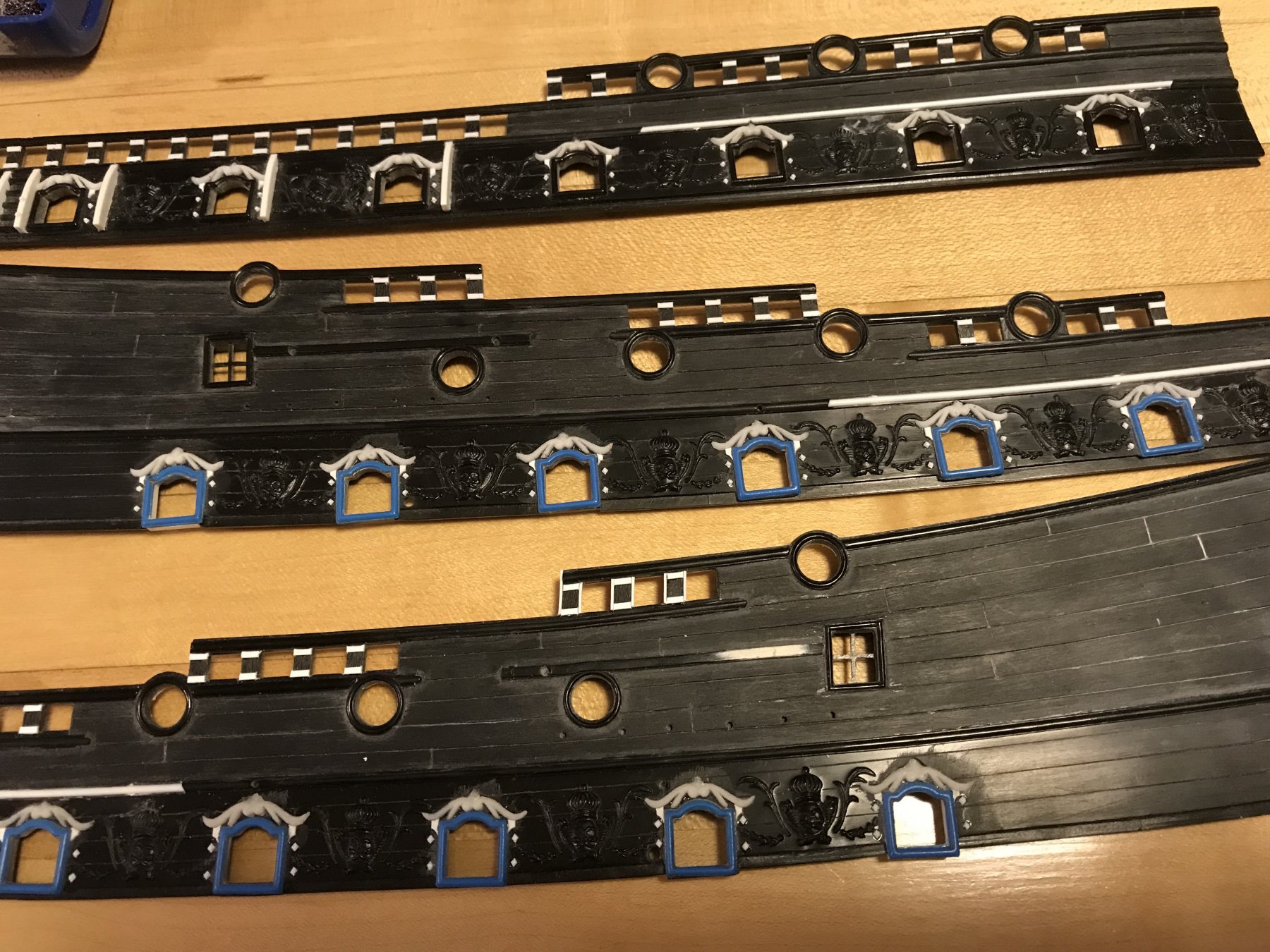
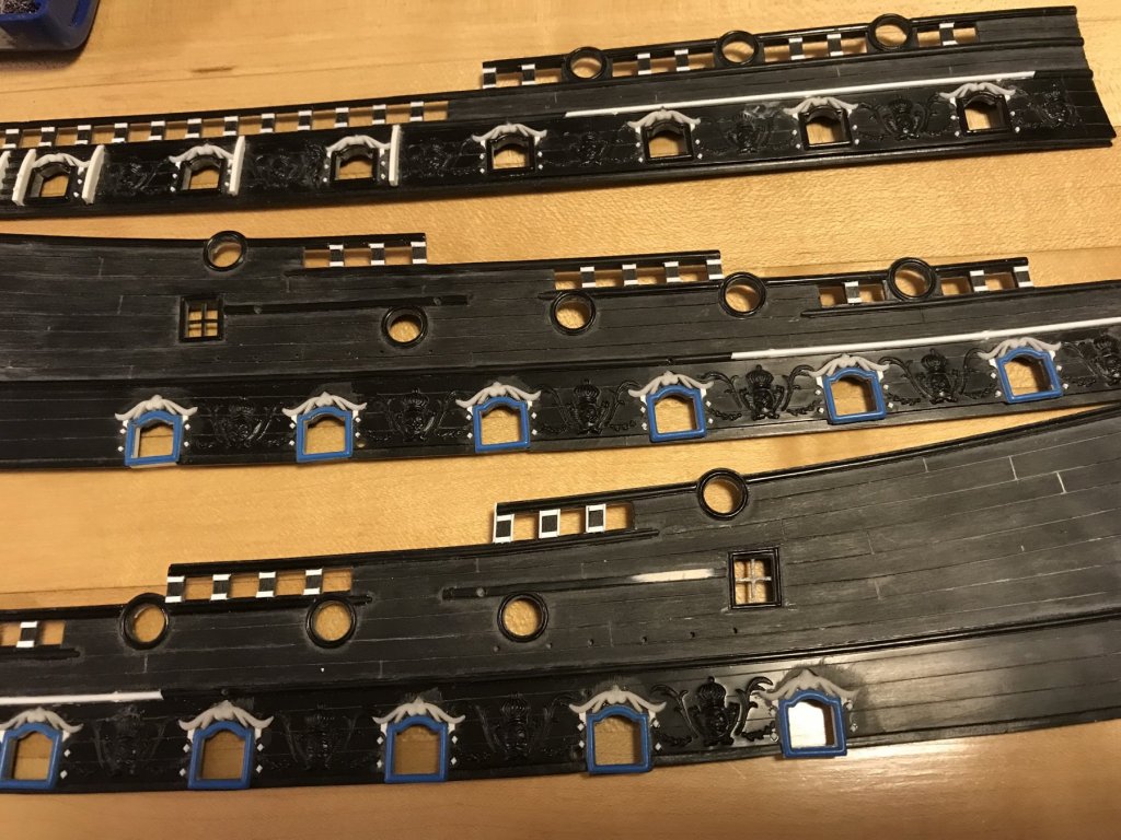
The reconcilliation of the two halves worked out neatly enough, and now they are twins. I’ve begun the rounding and relief work, and hope to make moulds and begin casting by the end of the week. In the meantime, I am adding a detail that I often see on the French arsenal-style models to the timberhead faces of the sheer rails. While I like this frame and panel effect for its own sake, I am hoping to accomplish a bit of visual trickery, in an effort to minimize one of the design defects of the kit. It is my opinion that the height of and spacing between the timberheads is exagerated, on the stock kit. The side members of the added frame detail will help close the space between timberheads by almost a 1/16”. And the paintwork will help to focus the eye on the smaller framed panel; I will paint the frame yellow ocher and I will use the darker ultra-marine blue for the sunken panel. The moulding on the outside of the caprails, themselves, will be done in gold, as will the caprail dolphins.

- 2,699 replies
-
- 6
-
-
- heller
- soleil royal
- (and 9 more)
-
Every time I turn around on this site, someone is building my newest, most favorite model. It had been a while since you posted Giorgo, and I had forgotten that Amalio had a peer in the fine art of arsenal modeling. Your Fleuron is a spectacular accomplishment in every way. I am glad to see that you are active again
-
The thought that just occurred to me is that the computer technology available to us today makes it easier than ever to master a build, and thus create a commercial kit, and furthermore (oh, yes, I raised it to that level of furthermore) to interest young people, kids, in the hobby. The primary obstacles to creating good, off the shelf and interesting scale models seem to be lifted now. I am all for modelers creating projects from scratch, however, we can only approach that ambition through our introduction to the hobby, via kits. As a parent, I realize this is a nurture vs. nature issue. At the same time, though, the whole concept of the “hobby shop” seems like a relic of bygone times. Not to soap-box too much, and if anything - to express my admiration for your drive to create your own model. Just thinking out loud. Just waxing on the shifting tides of generations.
- 132 replies
-
- 5
-
-
- charles martel
- battleship
- (and 1 more)
-
I love all of it - outstanding!! The sense of scale is awe-inspiring!
-
There is the frame of thought that supposes that, if five people all build the same model to the same plans - then you are very likely to see five very different models. While I believe that to be true, Sigi, I think your discernment brings you closest to the truth; a fantastic build in subject, form, material and execution. For me, it’s all about the lines, and your lines look true to me.
-
I think that using a mixture of lighter and darker pear staves will provide some differentiation, in the short term. Over time, though, the wood will oxidise and those differences will become much more muted. Just my two cents worth.