


gsdpic
-
Posts
523 -
Joined
-
Last visited
Content Type
Profiles
Forums
Gallery
Events
Posts posted by gsdpic
-
-
Welcome to MSW, from a NC State grad and former resident of Raleigh (way back in the late 80s, early 90s). I've always liked the looks of that ship but know nothing about it or the kit. I'd follow a build log if you start one.
- mtaylor and Keith Black
-
 2
2
-
Wow, that is amazing creativity and execution! The revised, frothier ocean water is much better, very convincing.
- Glen McGuire, mtaylor, Knocklouder and 1 other
-
3
-
 1
1
-
7 hours ago, Glen McGuire said:
On another note - seeing that you are also from Austin, how did your trees fare after the ice storm last month?
Mixed bag....three trees with little damage but two with pretty extensive damage. Most heartbreaking was a beautiful live oak that I think was planted when the house was built and was probably 35-40 years old. It had a nice full and symmetrical canopy. Now....well, it looks like a giant kraken took a bite out of the top center of the canopy, probably 50% gone. I had the broken branches cut out but will probably get an arborist out this fall to see if anything more can be done for it. But I did not lose power and usually work from home anyway, so not too much impact. Hope you managed ok through the ice as well.
- mtaylor, GrandpaPhil, FriedClams and 1 other
-
4
-
1 hour ago, Glen McGuire said:
I made the mistake of looking at it for too long right before I was going to bed last night and.....
I thought you were going to say "...and I had nightmares all night".
")
Looks good. Definitely the strangest build log on MSW right now.
- mtaylor, Glen McGuire, FriedClams and 2 others
-
4
-
1
-
Well done. The green and white is eye catching.
-
I'll add a redundant but much deserved "wow!" and "thanks!" It is amazing what you've accomplished with the Germania Nova and very generous of you to document it so thoroughly for the rest of us.
- mtaylor, FriedClams, KeithAug and 2 others
-
5
-
Thanks all for the likes and thanks Mike for the comment.
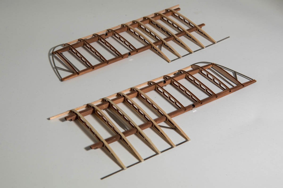
I've been working on the lower wings but have more to do. The picture below shows the current state. You can see that I still need to add the extra strip on the top and bottom of the last 5 ribs on each wing. There are then a few more details to add and of course some more diagonal tension cables and then the ailerons as well. I've made a few minor negative comments about this kit so to balance it out I'll praise the laser cut ribs. I cannot imagine how time consuming and tedious it would be to try to cut those by hand if doing this from scratch. And the laser cutting seems to be really well done, with no char marks on the front or back surfaces of the wood and just a couple very small tabs to hold the parts in. And also the parts fit together well....each rib has two notches that go over the lengthwise wood pieces. Many of them fit nicely without any adjustment and a few needed just a little bit of filing to get a nice fit. At least in some cases they also supplied an extra rib in case you break one. So, it has been a pleasure work on this part of the model.
- BLACK VIKING, BobG, Egilman and 12 others
-
15
-
Thanks for the likes and all the suggestions regarding the braces for the stabilizer and wing. I continue to defer that work. I received the wire that I ordered and it might be workable. But, the model also presents some problems with the attachment points for the braces on the stabilizer. So, I am considering that as well.
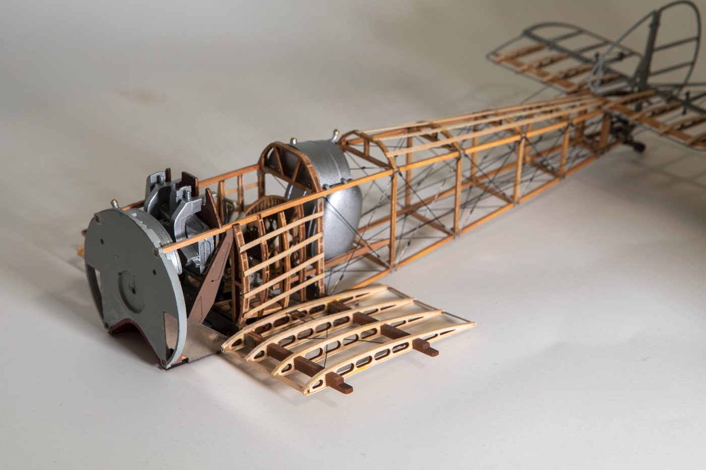
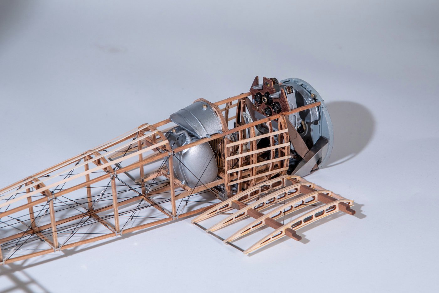
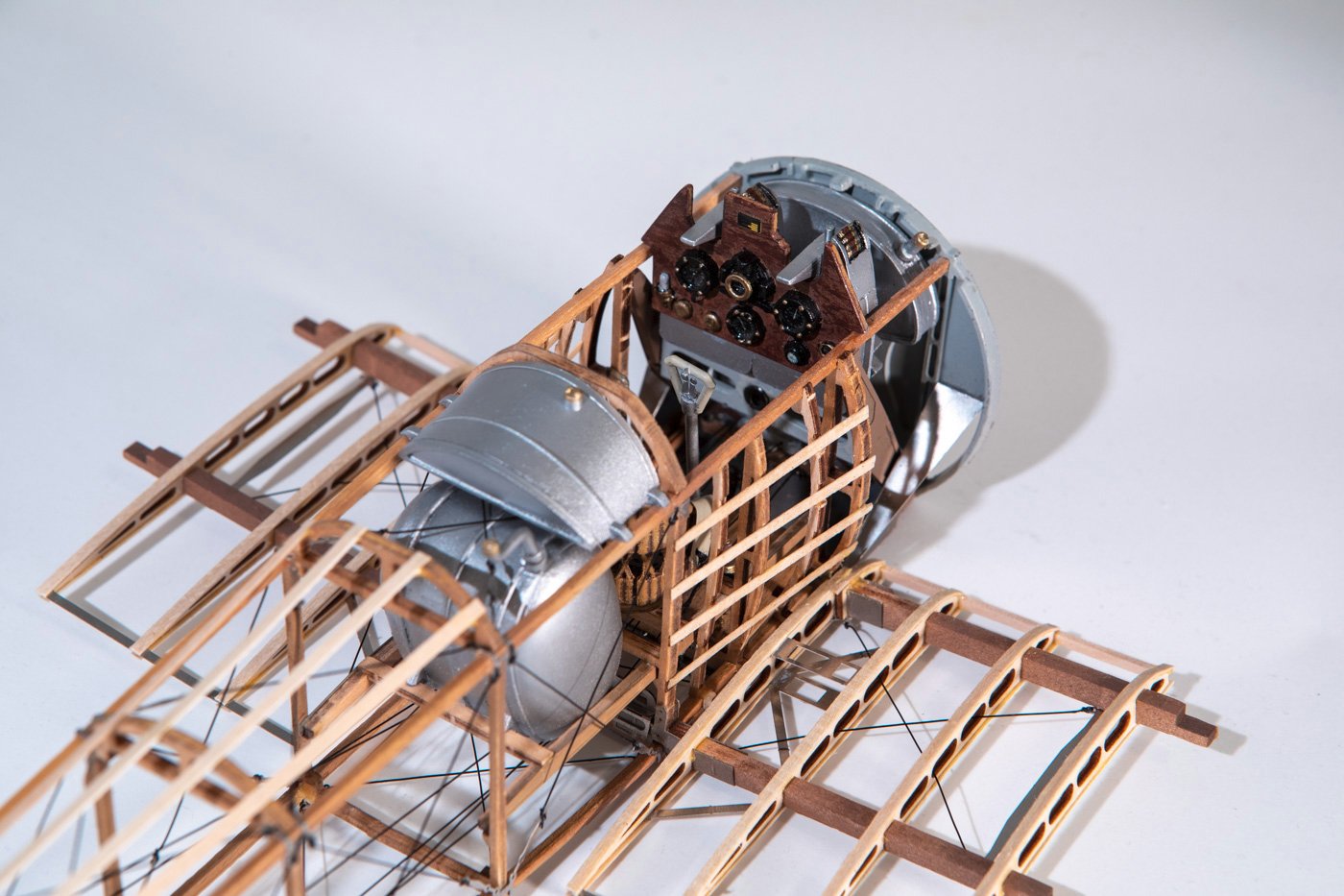
Meanwhile, I skipped that step and continued on with the next steps which added the ribs to the lower wing stubs and also did some additional work on the cockpit including the instrument panel. I got through all of those steps. Next I'll put the fuselage aside and start working on building the two outer sections of the lower wing. It was really good to get back into things where I felt like I was making a lot of progress.
Here are the pictures of the current state.
-
Hi Andy.....I suspect I know why you are asking this question. The timberheads on the last few frames supplied in my kit (and I suspect your as well) were not very progressive. The indentation on frame 26ish was almost as great as that on the last frame. I attempted to make it follow the plan a bit more and make them more progressive, though probably could have done even more than I did, as I ended up putting a bit of a "kink" in the cap rail at that point instead of allowing a completely smooth curve.
I bought a used copy online of the book "The Low Black Schooner" by John Rousmaniere, referenced in one of the other America build logs on MSW. It has quite a few contemporary paintings and a few early photographs from a few decades later. It is often hard to pick up small details in the paintings and often the details differ wildly, but I don't think any of them show any sort of sudden indentation in that area, they all indicate a more smooth curve. So, I'd vote for making it a more gradual transition.
-
-
10 hours ago, Canute said:
Some fishing line may work. 10 pound test line is small, but I think there are finer line. And they may come in black. Try the fly-fishing products.
Thanks. The other diagonal braces on the fuselage are black fishing line of unknown strength. It was supplied by the kit in an unlabelled reel. So using that is one alternative. Though I think I'd prefer something more silver or metallic looking.
6 hours ago, Jack12477 said:Look in the jewelry making section of Michael's craft stores. They carry very fine braided wire and crimps etc. I used them to make the cables for my ice yacht model.
Right, the stuff I bought off of amazon was under their jewelry making/beading category. I did not think to look for any sort of crimps, that could be very useful. And I wonder if a braided wire would be more flexible and easier to work with. Thanks.
-
Wow, beautiful result! One of my early builds, many years ago, is one of the Dumas Chris Craft boats. I've always loved the mahogany speed boats (who doesn't?) and hope to build another some day. If so, I can only hope it comes out half as nice as yours.
-
Thanks @hof00 for the tip. I've used that technique in the past but right now the only CA I have on hand is the gel variety and it does not work as well for this trick, as it does not soak into the thread. But I also noted that the holes in the photo etch pieces for the main wing are larger and easier to deal with. It is just the ones on the parts on the tail that are problematic.
Regardless, I ordered a small spool of stainless steel wire off of amazon. Once that gets here, I plan to experiment with it to see if that would be a better option for the wing bracing.
-
Thanks again for all the likes.
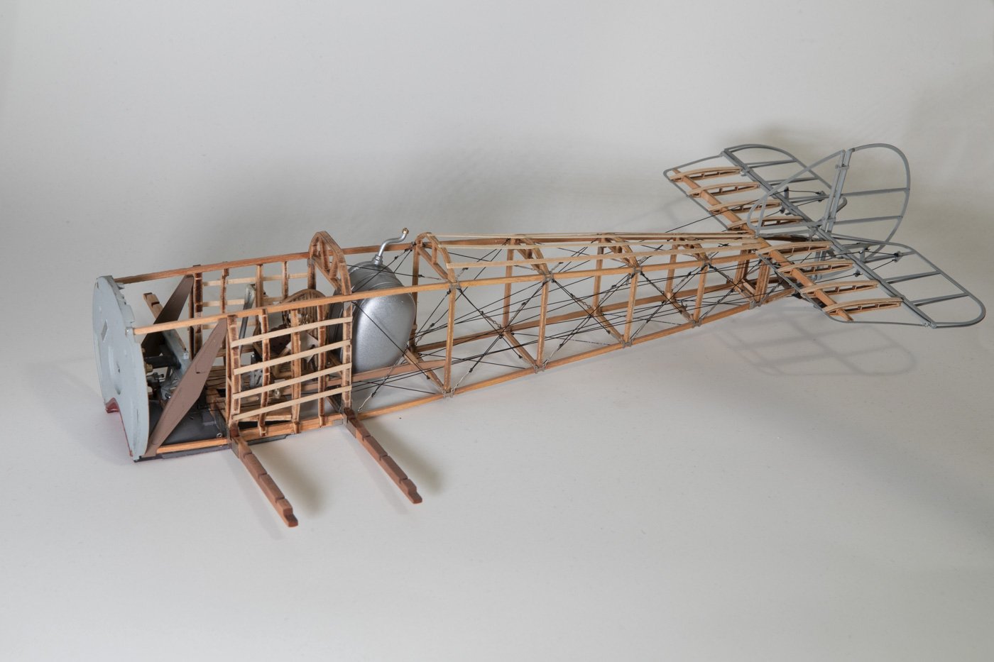
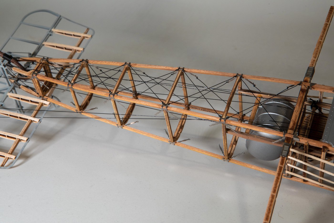
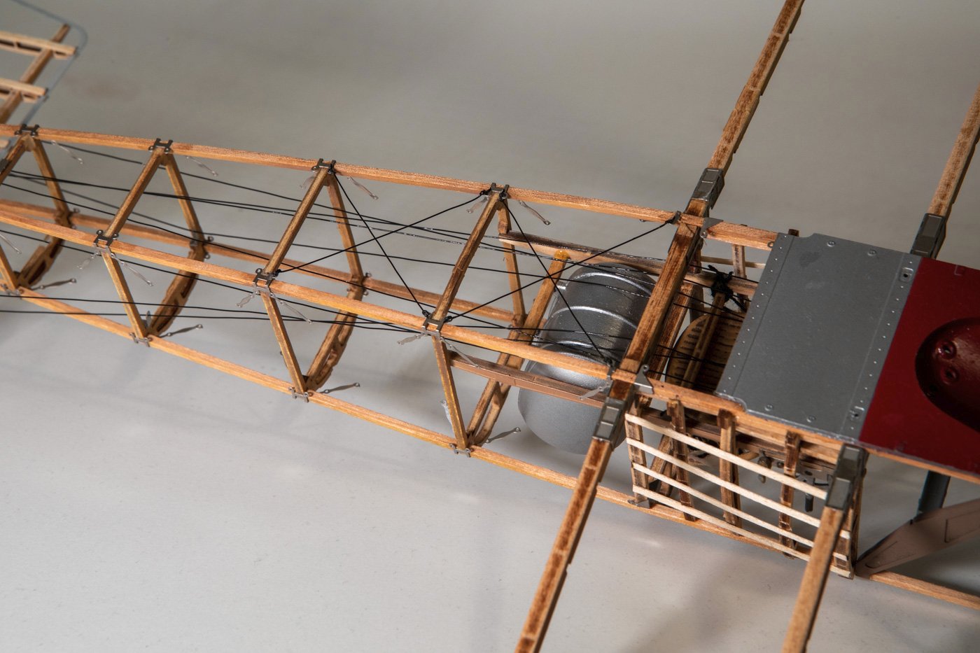
I realize these recent pictures pretty much look the same. But, I am now done with the 40 diagonal bracing wires on the fuselage. Who would've thought that a Sopwith Camel model would have more "rigging" than the yacht America?
Another example of the dubious order of steps in the instructions....do you see the four lengthwise wood strips across the top/back of the fuselage? The instructions had you glue those in place before doing the diagonal braces directly below them. That's just nuts, and fortunately I noticed and left those off until after the braces were in place.
So with that I am through step 17. Next up is some braces between the horizontal stabilizer and the rudder. For some reason, the kit shifts to recommending black cotton thread for these and the braces on the main wings, instead of the black fishing line that has been used so far. The cotton thread is a bit thicker, making it more difficult to feed through the holes in the photo etch bits that serve as end points. So, I am not sure if I will follow the instructions or just continue to use the fishing line for everything. I don't see the fishing line or the cotton thread as particularly representative of the real thing.
-
Interesting and unusual subject. After seeing what you did with the Cairo, I'll be following along with interest.
- Keith Black, Canute, mtaylor and 1 other
-
4
-
Looking good, Andy. Feel free to use anything you see in my build log. But be advised, I am a software guy, not a real engineer
-
Thanks to those who have looked in and especially to those who've hit the like button. Funny, I think I've been getting more likes for this than I ever did for the America build log. I'll just chalk that up to overall increased traffic on this site over the years.
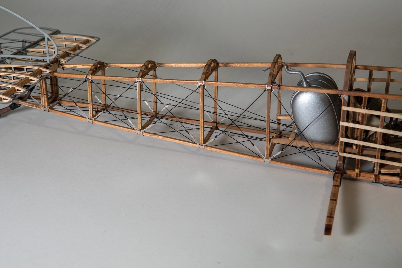
I am now half done with the fuselage tension cables, having completed those on the bottom and on the right side. Top and left side ones yet to do.
-
I've decided to proceed with the kit-supplied photo-etched turnbuckles and the fishing line for the tension cables. I figured at normal viewing distance the flat turnbuckles would give a good enough impression. Besides, one of the reasons I opted for this kit over the Model Airways one was the additional photo etch parts of this kit.
So I have now glued on (using CA) all the little photo-etched bits including the turnbuckles that act as end points for the tension cables. I then did the first four of those cables, starting on the bottom. It has gone ok so far but my hope is that when I get to the sides and top I will have gotten better at keeping the line taut. I have four done, 36 to go.
- ccoyle, king derelict, Roger Pellett and 15 others
-
16
-
 2
2
-
-
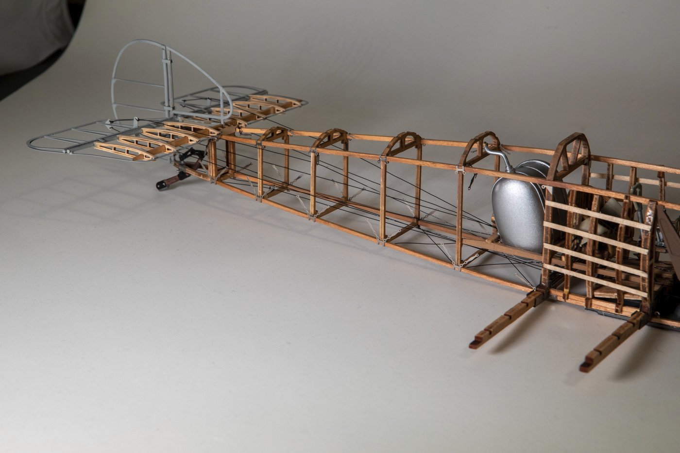
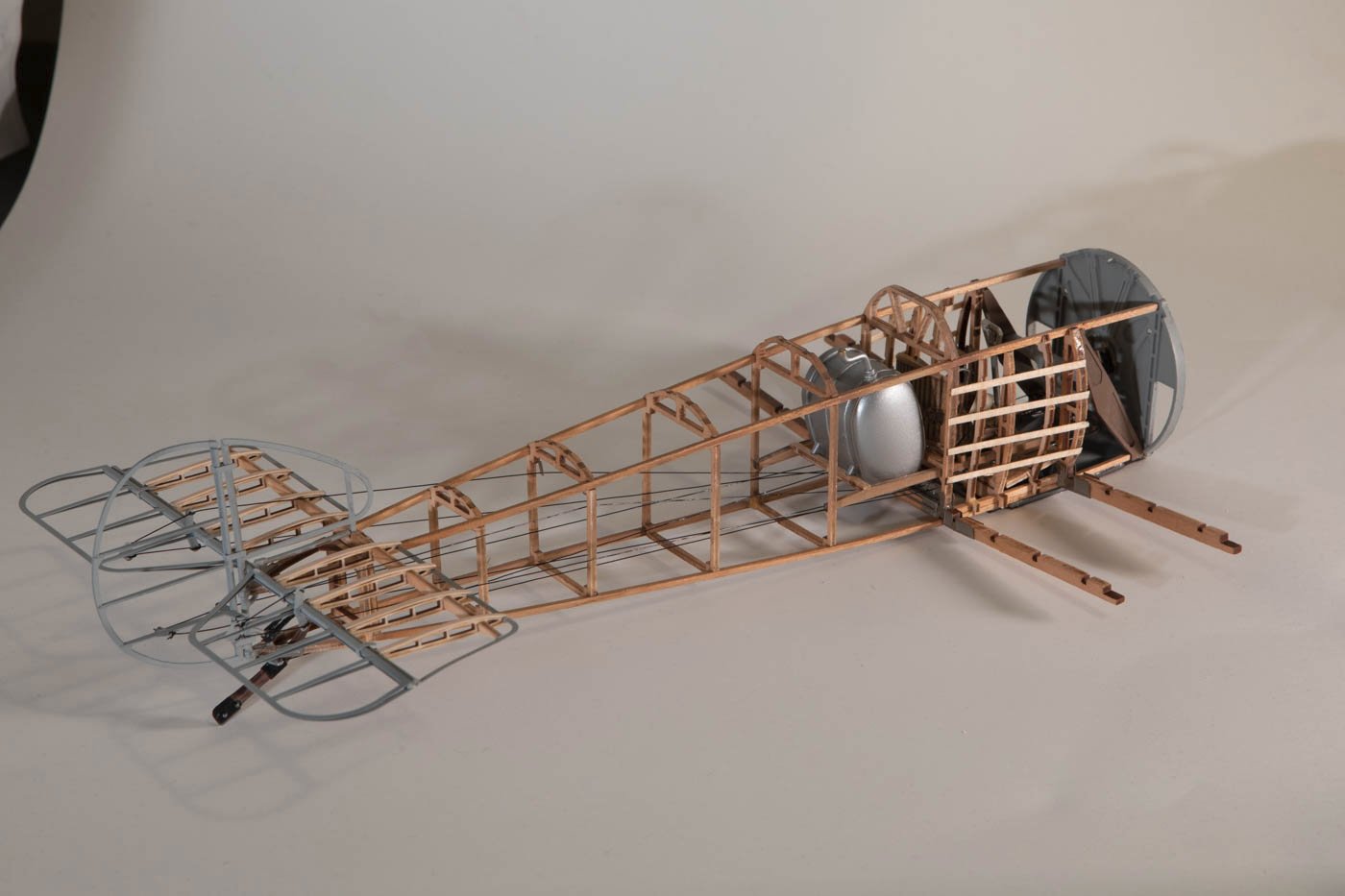
So, I am still out here, and I have resumed working a bit on the Sopwith Camel. The "handsome hound" in Ken/Canute's words found another (permanent, I hope) home a few months back. I then did a couple other smaller modelling projects before getting back to the Camel after the first of the year.
The picture below shows the current state. I am now through step 16 in the instructions, out of 47. The primary thing done since the last update are all the control cables for the elevator and rudder. The next step involves the tensioning cables that go diagonally across each of the rectangular spaces in the fuselage, 40 of them in all. Before proceeding with that, I need to decide if I am going to use the photo-etched turnbuckles or try to create something that is a little more three dimensional. I did a few experiments already though want to do more before I decide. There are probably about 100 of the things on the whole model.
The stuff I did was not without trials and tribulations. There was one picture in the instructions that was clearly wrong....two parts were glued together, then a couple steps later when they were used, one of those two parts was oriented 180 degrees differently from the picture shown where you glue them together. I am also getting more and more suspicious of the order of the steps. For example, there was no reason to glue in the seat before running those control cables, and all of the cables went under the seat. It would have been much easier to glue in the seat after doing the control cables. Oh well, nothing too serious or too different from most other models.
- CaptnBirdseye, Canute, mtaylor and 11 others
-
14
-
The alclad line of paints also have chrome, though not sure if how well they work on brass. I've used their chrome just a couple times on plastic parts. They are also applied by air brush. For chrome you first apply a gloss black base layer, then apply the chrome, then apply a clear top coat, so it is not a quick and easy process. I think, but am not certain, this might be a little more durable than the molotow chrome markers. I've used that once or twice as well, using the marker instead of the refill/airbrush suggested above.
-
Happy New Year! Glad to see another Bluejacket America build here. I'll follow along to see how it goes. Looks like you are off to a good start. The "cut out the template and flip it over" is basically the analog version of what I did with the scanner and flipping over the image in photoshop as described in my build log.
As for the inner surfaces of the frames....you might want to do at least a little work there. The bilge clamps and sheer clamps run along the inside of the frames and provide a lot of strength to the hull while fairing and planking. Having the inner surfaces smooth and fair may help with attaching the clamps to every frame which should help avoid accidental breakage of the frames.
- mtaylor and Knocklouder
-
2
-
Well done! Beautiful boat. I am sure your FIL will appreciate it very much.
-
Welcome to MSW! Former Raleigh resident and NC State grad here. I lived in Raleigh in the early and mid '90s.
SEGUIN by schooner - FINISHED - BlueJacket Shipcrafters - 1:48 - RADIO - Steam Tug
in - Kit build logs for subjects built from 1851 - 1900
Posted
Following along to see how things go with your RC adventure. It seems well planned out so far, with a couple issues dodged.